JP2016202808A - Twin tub washing machine - Google Patents

Twin tub washing machine Download PDF

Info

Publication number
JP2016202808A
JP2016202808A JP2015091501A JP2015091501A JP2016202808A JP 2016202808 A JP2016202808 A JP 2016202808A JP 2015091501 A JP2015091501 A JP 2015091501A JP 2015091501 A JP2015091501 A JP 2015091501A JP 2016202808 A JP2016202808 A JP 2016202808A
Authority
JP
Japan
Prior art keywords
washing
water supply
tub
dewatering
dehydration
Prior art date
Legal status (The legal status is an assumption and is not a legal conclusion. Google has not performed a legal analysis and makes no representation as to the accuracy of the status listed.)
Pending
Application number
JP2015091501A
Other languages
Japanese (ja)
Inventor
大輔 秋葉
Daisuke Akiba
大輔 秋葉
茂実 森田
Shigemi Morita
茂実 森田
林 美穂
Miho Hayashi
美穂 林
Current Assignee (The listed assignees may be inaccurate. Google has not performed a legal analysis and makes no representation or warranty as to the accuracy of the list.)
Toshiba Lifestyle Products and Services Corp
Original Assignee
Toshiba Lifestyle Products and Services Corp
Priority date (The priority date is an assumption and is not a legal conclusion. Google has not performed a legal analysis and makes no representation as to the accuracy of the date listed.)
Filing date
Publication date
Application filed by Toshiba Lifestyle Products and Services Corp filed Critical Toshiba Lifestyle Products and Services Corp
Priority to JP2015091501A priority Critical patent/JP2016202808A/en
Publication of JP2016202808A publication Critical patent/JP2016202808A/en
Pending legal-status Critical Current

Links

Images

Landscapes

  • Main Body Construction Of Washing Machines And Laundry Dryers (AREA)
  • Detail Structures Of Washing Machines And Dryers (AREA)
  • Control Of Washing Machine And Dryer (AREA)
  • Accessory Of Washing/Drying Machine, Commercial Washing/Drying Machine, Other Washing/Drying Machine (AREA)

Abstract

PROBLEM TO BE SOLVED: To enable a washing operation on a dewatering tub side while having a relatively simple configuration.SOLUTION: A twin tub washing machine of an embodiment includes a washing tub and a dewatering tub having a dewatering basket. The twin tub washing machine which executes a washing operation comprising washing, rinsing and dewatering on the basis of a manual operation includes: a dewatering tub side drain valve for opening/closing a drain passage of the dewatering tub; a water supply switching mechanism for switching between the water supply to the washing tub and the water supply to the dewatering tub through the manual operation of an operation knob provided at an operation part; and a dewatering tub side drain valve switching mechanism for blocking the dewatering tub side drain valve being interlocked with the water supply switch to the dewatering tub side through the operation knob of the water supply switching mechanism.SELECTED DRAWING: Figure 1

Description

本発明の実施形態は二槽式洗濯機に関する。   Embodiments described herein relate generally to a two-tub washing machine.

二槽式洗濯機は、一般に、洗濯槽と、脱水かごを有する脱水槽とを備え、洗い、すすぎ、脱水からなる洗濯運転の各行程を手動操作に基づいて実施するように構成されている。この二槽式洗濯機は、高齢者の方を中心に依然として需要がある。この二槽式洗濯機においては、ユーザは、まず、洗濯物及び洗剤を洗濯槽に投入し、所望の水位までの給水を行い、洗いタイマーを操作して所望時間の洗い行程を実施させる。次いで、排水、給水を行い、洗いタイマーを操作してすすぎ行程を実施させる。その後、すすぎ行程までが終了した洗濯物を、脱水槽の脱水かご内に移し替え、脱水タイマーを操作して所望時間の脱水行程を実施させるようになっている。   The two-tub washing machine generally includes a washing tub and a dewatering tub having a dewatering basket, and is configured to perform each step of a washing operation including washing, rinsing, and dehydration based on a manual operation. This two-tub washing machine is still in demand, especially for elderly people. In this two-tub washing machine, the user first puts laundry and detergent into the washing tub, supplies water to a desired water level, operates a washing timer, and performs a washing process for a desired time. Next, drainage and water supply are performed, and a rinsing process is performed by operating a washing timer. Thereafter, the laundry after the rinsing process is completed is transferred to the dehydration basket of the dehydration tank, and the dehydration process is performed by operating the dehydration timer.

上記のような二槽式洗濯機では、洗濯槽側でのみ洗い及びすすぎの行程を行うため、洗い行程後の洗濯液を一旦捨てた上ですすぎを行う必要があり、洗濯液を二度使用することはできなかった。また、洗い行程後に中間脱水を行った後、すすぎ行程を実施し、その後最終脱水の行程を実施したいような場合、洗濯槽と脱水槽との間で何度も洗濯物を移し替える必要があり、手間や労力のかかる作業が必要となる。そこで、例えば特許文献1には、脱水槽側で、脱水は勿論、洗いやすすぎの洗濯運転を実施することを可能とした二槽式洗濯機が開示されている。この特許文献1の二槽式洗濯機によれば、ユーザが洗濯物の移し替えを行うことなく、脱水槽側だけで洗濯を行うことが可能となる。   In the two-tank washing machine as described above, since the washing and rinsing process is performed only on the washing tub side, the washing liquid after the washing process needs to be discarded and then rinsed, and the washing liquid is used twice. I couldn't. In addition, after performing the intermediate dehydration after the washing process, if it is necessary to carry out the rinsing process and then perform the final dehydration process, it is necessary to transfer the laundry many times between the washing tub and the dehydrating tub. , Laborious and labor intensive work is required. Thus, for example, Patent Document 1 discloses a two-tank washing machine that can perform a washing operation that is easy to wash as well as dewatering on the side of the dehydrating tub. According to the two-tub washing machine of Patent Document 1, it is possible for a user to perform washing only on the side of the dewatering tank without transferring the laundry.

特開平11−300075号公報Japanese Patent Laid-Open No. 11-300075

しかしながら、上記特許文献1に記載された二槽式洗濯機では、洗濯槽及び脱水槽に水を供給する2本の給水管に電気的に動作される給水弁を夫々設け、洗濯槽及び脱水槽の排水管に電気的に動作される排水弁を夫々設け、マイコンからなる制御部が設けられる。そして、制御部が、水位センサの信号等に基づいて、2つの給水弁、2つの排水弁、洗濯用のモータ、脱水用のモータを夫々制御して、洗濯運転を進める構成となっている。この場合、特許文献1の二槽式洗濯機は、いわば半自動式のものであり、洗濯の各行程を手動で進める本来の二槽式洗濯機からかけ離れた、複雑な構成のものとなっている。   However, in the two-tub type washing machine described in Patent Document 1, a water supply valve that is electrically operated is provided in each of two water supply pipes that supply water to the washing tub and the dehydration tub, respectively. Each drainage pipe is provided with a drain valve that is electrically operated, and a control unit comprising a microcomputer is provided. The control unit is configured to advance the washing operation by controlling the two water supply valves, the two drain valves, the washing motor, and the dehydrating motor, respectively, based on the signal of the water level sensor. In this case, the two-tank washing machine of Patent Document 1 is a so-called semi-automatic machine, and has a complicated configuration that is far from the original two-tank washing machine that manually advances each step of washing. .

そこで、二槽式洗濯機において、比較的簡単な構成で済ませながら、脱水槽側での洗濯運転の実施を可能とする。   Therefore, in the two-tank washing machine, it is possible to carry out the washing operation on the dewatering tub side while having a relatively simple configuration.

実施形態の二槽式洗濯機は、洗濯槽と、脱水かごを有する脱水槽とを備え、洗い、すすぎ、脱水からなる洗濯運転を手動操作に基づいて実施するものにおいて、前記脱水槽の排水路を開閉する脱水槽側排水弁と、操作部に設けられた操作つまみの手動操作により給水口からの前記洗濯槽への給水と前記脱水槽への給水とを切替える給水切替機構と、前記給水切替機構の操作つまみによる前記脱水槽側への給水切替えと連動して、前記脱水槽側排水弁を閉塞させる脱水槽側排水弁切替機構とを具備するところに特徴を有する。   The two-tank washing machine of the embodiment includes a washing tub and a dehydrating tub having a dewatering basket, and performs a washing operation including washing, rinsing, and dehydration based on a manual operation. A water supply switching mechanism for switching between water supply to the washing tub and water supply to the dehydration tub from a water supply port by manual operation of an operation knob provided in the operation unit, and the water supply switching It is characterized in that it comprises a dewatering tank side drain valve switching mechanism that closes the dewatering tank side drain valve in conjunction with the switching of water supply to the dehydrating tank side by the operation knob of the mechanism.

一実施形態を示すもので、二槽式洗濯機の全体構成を示す縦断正面図A longitudinal front view showing an overall configuration of a two-tub washing machine, showing an embodiment 脱水槽側排水弁の構造を示す概略的縦断面図Schematic longitudinal section showing the structure of the drainage tank side drain valve 給水切替機構の要部構成を模式的に示す縦断正面図Longitudinal front view schematically showing the main configuration of the water supply switching mechanism 操作パネルの平面図Top view of the operation panel 操作つまみの3つの位置とワイヤとの関係を模式的に示す縦断正面図A longitudinal front view schematically showing the relationship between the three positions of the operation knob and the wire. 操作つまみの3つの位置と給水位置及び脱水槽側排水弁の開閉との関係を示す図The figure which shows the relationship between three positions of an operation knob, a water supply position, and opening and closing of the dewatering tank side drain valve

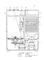
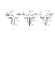
以下、一実施形態について、図面を参照しながら説明する。図1は本実施形態に係る二槽式洗濯機1の全体構成を概略的に示しており、ここで、矩形容器状をなす基台2上には、例えば合成樹脂製の槽体3が設けられている。この槽体3には、洗濯槽4と脱水槽5とが左右に並置された状態で一体的に設けられている。前記槽体3の上部には、上部カバー31が装着されている。前記洗濯槽4の内周側部の一箇所には、溢水ストレーナ6が装着されており、その内側に設けられた上向きの筒状の溢水口を越えた水が、図示しない溢水ホース及び排水ホースを順次通して外部に排水されるようになっている。   Hereinafter, an embodiment will be described with reference to the drawings. FIG. 1 schematically shows an overall configuration of a two-tub washing machine 1 according to the present embodiment. Here, a tank body 3 made of, for example, a synthetic resin is provided on a base 2 having a rectangular container shape. It has been. The tank 3 is integrally provided with a washing tub 4 and a dewatering tub 5 arranged side by side. An upper cover 31 is attached to the upper part of the tank body 3. An overflow strainer 6 is mounted at one place on the inner peripheral side of the washing tub 4, and water that passes through an upward cylindrical overflow port provided inside the overflow basin is not shown. The water is drained to the outside through this.

前記洗濯槽4の内下部には、パルセータ7が回転可能に配設されている。このとき、洗濯槽4の底部には、上下方向に貫通して延びる駆動軸26が、洗濯槽4の外底部側に設けられた軸受機構部25に回転自在に支持されており、前記パルセータ7は、その駆動軸26の上端に取付けられている。前記基台2内には、駆動軸26を正逆方向に回転駆動するための駆動機構部27が設けられている。この駆動機構部27は、前記基台2に取付けられた洗濯用モータ28や、この洗濯用モータ28の回転を前記駆動軸26に伝達するベルト伝達機構29等から構成されている。   A pulsator 7 is rotatably disposed inside and below the washing tub 4. At this time, a drive shaft 26 extending vertically through the bottom of the washing tub 4 is rotatably supported by a bearing mechanism portion 25 provided on the outer bottom side of the washing tub 4. Is attached to the upper end of the drive shaft 26. A driving mechanism 27 for rotating the drive shaft 26 in the forward and reverse directions is provided in the base 2. The drive mechanism unit 27 includes a washing motor 28 attached to the base 2 and a belt transmission mechanism 29 that transmits the rotation of the washing motor 28 to the drive shaft 26.

前記洗濯用モータ28は、例えば誘導モータから構成され、後述する洗濯タイマーのオン時に、図示しない駆動回路を介して通電される。これにて、パルセータ7は、洗濯用モータ28によりベルト伝達機構29を介して、正逆方向に低速回転駆動される。これにより、洗濯槽2内に収容された洗濯物(図示せず)を洗濯水と共に撹拌する水流を生成するようになっている。   The washing motor 28 is composed of, for example, an induction motor, and is energized via a drive circuit (not shown) when a washing timer described later is turned on. Thus, the pulsator 7 is driven to rotate at a low speed in the forward and reverse directions by the washing motor 28 via the belt transmission mechanism 29. Thereby, the water flow which stirs the laundry (not shown) accommodated in the washing tub 2 with wash water is produced | generated.

前記脱水槽5の内部には、洗濯物を収容する脱水かご8が、垂直軸を中心に回転可能に配設されている。この脱水かご8は、上面が開口した円筒容器をなし、その周側部には全体に渡って多数の通水孔9が設けられており、以て脱水かご8の内外が連通状態とされている。この脱水かご8の上端部には、リング状のバランサ10が設けられている。また、脱水かご8の上面開口部には、図示しない脱水キャップが装着されるようになっている。   Inside the dewatering tub 5, a dewatering basket 8 for storing laundry is disposed so as to be rotatable about a vertical axis. The dewatering basket 8 is a cylindrical container having an open top surface, and a large number of water passage holes 9 are provided on the entire peripheral side thereof, so that the inside and outside of the dewatering basket 8 are in communication with each other. Yes. A ring-shaped balancer 10 is provided at the upper end of the dewatering basket 8. A dehydration cap (not shown) is attached to the upper surface opening of the dehydration basket 8.

前記基台2内には、脱水槽5の下方に位置して、前記脱水かご8を回転駆動するための脱水用モータ11が設けられていると共に、その脱水用モータ11の回転を制止するブレーキ装置12が配設されている。前記脱水用モータ11は、例えば誘導モータから構成され、当該脱水用モータ11の回転軸11aは、脱水かご8のシャフト8aに連結されている。これにより、脱水用モータ11は、直接的に脱水かご8を回転させるように構成されている。   A dehydrating motor 11 for rotationally driving the dehydrating basket 8 is provided in the base 2 below the dehydrating tank 5 and a brake for stopping the dehydrating motor 11 from rotating. A device 12 is provided. The dehydrating motor 11 is composed of, for example, an induction motor, and the rotating shaft 11 a of the dehydrating motor 11 is connected to the shaft 8 a of the dehydrating basket 8. Thereby, the dehydrating motor 11 is configured to rotate the dehydrating basket 8 directly.

この脱水用モータ11は、後述する脱水タイマーのオン時、及び、脱水槽洗いタイマーのオン時に、図示しない駆動回路を介して通電される。この場合、脱水タイマーのオン時には、脱水用モータ11が連続通電されて、脱水かご8が一方向に高速回転され、脱水かご8内に収容された洗濯物が遠心脱水される。そして、後述するように、脱水槽洗いタイマーのオン時には、脱水用モータ11が正逆方向に交互に間欠駆動される。尚、脱水槽5の上面には脱水蓋33が開閉可能に設けられ、脱水蓋33の開放時には、図示しないスイッチが動作して脱水用モータ11の通電が停止されると共に、前記ブレーキ装置12が作動されるようになっている。   The dehydrating motor 11 is energized via a drive circuit (not shown) when a dehydrating timer, which will be described later, is turned on and when a dehydrating tank washing timer is turned on. In this case, when the dehydration timer is on, the dehydration motor 11 is continuously energized, the dehydration basket 8 is rotated at a high speed in one direction, and the laundry stored in the dehydration basket 8 is centrifugally dehydrated. As will be described later, when the dewatering tank washing timer is on, the dewatering motor 11 is intermittently driven alternately in the forward and reverse directions. A dehydration lid 33 is provided on the upper surface of the dehydration tank 5 so that the dehydration lid 33 can be opened and closed. When the dehydration lid 33 is opened, a switch (not shown) is operated to stop energization of the dehydration motor 11 and the brake device 12 It is to be activated.

前記洗濯槽4の底部には、排水口13が設けられており、この排水口13には排水管路14が接続されている。前記排水管路14には、洗濯槽側排水弁15が設けられている。この洗濯槽側排水弁15は、次に述べる脱水側排水弁18と同等の構成を備えており、操作用のワイヤ24(破線で示す)により開閉動作するようになっている。排水管路14の出口側端部には、図示しない排水ホースが接続され、洗濯槽側排水弁15の開放時に外部への排水が行われるようになっている。   A drain port 13 is provided at the bottom of the washing tub 4, and a drain line 14 is connected to the drain port 13. The drain pipe 14 is provided with a washing tub side drain valve 15. The washing tub side drain valve 15 has the same configuration as the dewatering side drain valve 18 described below, and is opened and closed by an operation wire 24 (shown by a broken line). A drainage hose (not shown) is connected to the outlet side end of the drainage pipe 14 so that drainage to the outside is performed when the washing tub side drainage valve 15 is opened.

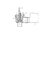
前記脱水槽5の底部には、排水口16が設けられており、この排水口16には排水路としての脱水側排水管路17が接続されている。前記脱水側排水管路17には、脱水槽側排水弁18が設けられている。図2は、この脱水槽側排水弁18の構成を示している。即ち、脱水槽側排水弁18は、弁ケース19を備え、弁ケース19の側面の入口部には、前記脱水側排水管路17の先端部が接続され、弁ケース19の下面の出口部は、前記排水管路14の途中部に接続されている。弁ケース19の出口部部分には、弁座19aが設けられている。   A drain port 16 is provided at the bottom of the dewatering tank 5, and a dewatering side drain pipe 17 as a drain channel is connected to the drain port 16. The dewatering side drain pipe 17 is provided with a dewatering tank side drain valve 18. FIG. 2 shows the configuration of the dewatering tank side drain valve 18. That is, the dewatering tank side drain valve 18 includes a valve case 19, the tip of the dewatering side drain pipe 17 is connected to the inlet of the side of the valve case 19, and the outlet of the lower surface of the valve case 19 is , Connected to the middle part of the drain pipe 14. A valve seat 19 a is provided at the outlet portion of the valve case 19.

前記弁ケース19の内部には、ベローズ状の弁体20が設けられている。この弁体20は、圧縮スプリング21により常に弁座19aに圧接する方向に付勢されており、操作力(上方への引張り力)が作用していない状態では、弁座19aに圧接して閉塞状態に保つように構成されている。そして、弁体20の内側には弁棒20aが取付けられ、その弁棒20aに連結スプリング22を介して操作用のワイヤ23の先端部が接続されている。図1に破線で示すように、前記ワイヤ23の基端部は、後述する給水先切替用の第4の操作つまみ39に接続されている。これにて、操作つまみ39の操作に伴うワイヤ23の動作(引張り操作)により、脱水槽側排水弁18が開放状態とされ、脱水槽5内の水が排水管路14を通って外部に排水されるようになっている。   A bellows-like valve body 20 is provided inside the valve case 19. The valve body 20 is always urged by the compression spring 21 in the direction in which it is pressed against the valve seat 19a. When no operating force (upward pulling force) is applied, the valve body 20 is pressed against the valve seat 19a and closed. It is configured to keep in a state. A valve rod 20 a is attached to the inside of the valve body 20, and a distal end portion of an operation wire 23 is connected to the valve rod 20 a via a coupling spring 22. As shown by a broken line in FIG. 1, the proximal end portion of the wire 23 is connected to a fourth operation knob 39 for switching a water supply destination, which will be described later. Thus, the operation of the wire 23 accompanying the operation of the operation knob 39 (pulling operation) opens the dewatering tank side drain valve 18, and the water in the dewatering tank 5 drains to the outside through the drain pipe 14. It has come to be.

また、上記洗濯槽側排水弁15についても、脱水槽側排水弁18と同様の構成を備えており、図1に示すように、操作用のワイヤ24が、後述する水流切替用および排水弁開閉用の第2の操作つまみ36に接続されている。これにて、後述する図5にも示すように、操作つまみ36の回動操作に伴うワイヤ24の動作(引張り操作)により、洗濯槽側排水弁15が開放状態とされ、洗濯槽4内の水が外部に排水される。尚、図示はしないが、前記脱水槽5の上部寄り部位には、溢水口が設けられ、脱水槽5内の水位がその溢水口を越えたときには、上記した溢水ホースを通して外部に排水される。   The washing tub-side drain valve 15 also has the same configuration as the dewatering tub-side drain valve 18, and as shown in FIG. 1, an operation wire 24 is used for switching the water flow and opening / closing the drain valve, which will be described later. The second operation knob 36 is connected. Thus, as shown in FIG. 5 to be described later, the operation of the wire 24 accompanying the turning operation of the operation knob 36 (pulling operation) opens the washing tub side drain valve 15, and the inside of the washing tub 4. Water is drained to the outside. Although not shown, an overflow port is provided near the upper portion of the dewatering tank 5, and when the water level in the dewatering tank 5 exceeds the overflow port, the water is discharged to the outside through the overflow hose.

前記上部カバー31には、前記洗濯槽4の上面開口部を開閉する洗濯蓋32が着脱可能に設けられていると共に、前記脱水槽5の上面開口部を開閉する脱水蓋33が設けられている。上部カバー31の後部には、操作部としての操作パネル34が設けられている。図4にも示すように、操作パネル34には、左から順に、洗いタイマー用の第1の操作つまみ35、水流切替用および洗濯槽側排水弁開閉用の第2の操作つまみ36、脱水・脱水槽洗いタイマー用の第3の操作つまみ37、給水口38、給水先切替用の第4の操作つまみ39が、横方向に並んで設けられている。そのうち給水先切替用の第4の操作つまみ39は、スライド式とされている。   The upper cover 31 is detachably provided with a laundry lid 32 that opens and closes the upper surface opening of the washing tub 4, and a dehydration lid 33 that opens and closes the upper surface opening of the dehydration tub 5. . An operation panel 34 as an operation unit is provided at the rear part of the upper cover 31. As shown in FIG. 4, the operation panel 34 includes, in order from the left, a first operation knob 35 for the washing timer, a second operation knob 36 for switching the water flow and opening / closing the drain valve on the washing tub, A third operation knob 37 for the dewatering tank washing timer, a water supply port 38, and a fourth operation knob 39 for switching the water supply destination are provided side by side in the horizontal direction. Among them, the fourth operation knob 39 for switching the water supply destination is a slide type.

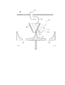
前記給水口38は、図示しない給水ホースの先端部が接続されるものであり、その給水ホースの基端部は、例えば水道の蛇口に接続される。そして、図1、図3に示すように、上部カバー31内には、ユーザが水道の蛇口を開くことに伴い給水口38から供給される水を、前記洗濯槽4への給水と、前記脱水槽5への給水との間で、給水位置(給水方向)を選択的に切替えるための給水切替機構40が設けられている。図3に示すように、この給水切替機構40は、給水管41、給水切替部材42、水受部43、及び後述する第4の操作つまみ39等から構成される。   The water supply port 38 is connected to a distal end portion of a water supply hose (not shown), and a proximal end portion of the water supply hose is connected to, for example, a faucet. As shown in FIGS. 1 and 3, the water supplied from the water supply port 38 when the user opens the water tap is supplied to the upper cover 31, and the water supplied to the washing tub 4 and the drainage are removed. A water supply switching mechanism 40 for selectively switching the water supply position (water supply direction) between water supply to the water tank 5 is provided. As shown in FIG. 3, the water supply switching mechanism 40 includes a water supply pipe 41, a water supply switching member 42, a water receiving portion 43, a fourth operation knob 39, which will be described later, and the like.

前記給水管41は、給水口38から連続して延び、給水切替部材42の上部に位置して、その下端部の出口部が下向きに配置されている。前記水受部43は、給水管41の出口部から流下した水を、給水切替部材42を通して受ける薄型容器状をなしていると共に、底部の中央部には、振分け凸部43aが上方に凸となるように設けられ、内部が左右に区切られている。そして、水受部43の左側部分の底部には、前記洗濯槽4と連通する洗濯槽側出口44が設けられており、右側部分の底部には、前記脱水槽5と連通する(脱水かご8の上方に開口する)脱水槽側出口45が設けられている。尚、洗濯槽側出口44及び脱水槽側出口45は、最も低い位置に設けられている。   The water supply pipe 41 extends continuously from the water supply port 38, is located at the upper part of the water supply switching member 42, and the outlet portion at the lower end thereof is disposed downward. The water receiving portion 43 has a thin container shape that receives the water flowing down from the outlet portion of the water supply pipe 41 through the water supply switching member 42, and the distribution convex portion 43 a protrudes upward in the central portion of the bottom portion. The inside is divided into right and left. A washing tub side outlet 44 communicating with the washing tub 4 is provided at the bottom of the left portion of the water receiving portion 43, and the dehydrating tub 5 is communicated with the bottom of the right portion (dehydration basket 8). A dewatering tank side outlet 45 (opening above) is provided. The washing tub side outlet 44 and the dewatering tub side outlet 45 are provided at the lowest position.

前記給水切替部材42は、前記給水管41と、水受部43(振分け凸部43a)との間に位置して図で左右方向に移動可能に設けられ、上下面が開口したテーパ容器状をなし、上方が広く下に行くほどすぼまるような形状をなしている。この給水切替部材42は、後述する第4の操作つまみ39の手動操作により、図3に実線で示す左位置、破線で示す中位置、二点鎖線で示す右位置の3箇所のいずれかに位置されるようになっている。このとき、給水切替部材42の上端開口部は、いずれの位置にあっても給水管41の出口部の下方に臨んで位置している。また、給水切替部材42の下端開口部は、左位置において振分け凸部43aの左側に位置し、中位置及び右位置において、振分け凸部43aの右側に位置するように構成されている。   The water supply switching member 42 is located between the water supply pipe 41 and the water receiving portion 43 (distribution convex portion 43a) and is provided so as to be movable in the left-right direction in the figure, and has a tapered container shape with upper and lower surfaces opened. None, with a shape that becomes narrower as the upper side becomes wider downward. The water supply switching member 42 is positioned at any one of three positions, a left position indicated by a solid line, a middle position indicated by a broken line, and a right position indicated by a two-dot chain line in FIG. 3 by manual operation of a fourth operation knob 39 described later. It has come to be. At this time, the upper end opening of the water supply switching member 42 is located below the outlet of the water supply pipe 41 regardless of the position. Further, the lower end opening of the water supply switching member 42 is configured to be positioned on the left side of the distribution convex portion 43a at the left position, and to be positioned on the right side of the distribution convex portion 43a at the middle position and the right position.

これにて、給水切替部材42の左位置においては、給水口38から給水管41を通って供給された水が、給水切替部材42を通って水受部43の左側に流下し、洗濯槽側出口44から洗濯槽4内に給水される。これに対し、給水切替部材42の中位置及び左位置においては、給水口38から給水管41を通って供給された水が、給水切替部材42を通って水受部43の右側に流下し、脱水槽側出口45から脱水槽5内に給水される。このように、給水切替機構40は、給水切替部材22の移動によって、洗濯槽4側への給水と、脱水槽5側への給水とを切替えるように構成されている。   Thus, at the left position of the water supply switching member 42, the water supplied through the water supply pipe 41 from the water supply port 38 flows down to the left side of the water receiving portion 43 through the water supply switching member 42, and the washing tub side Water is supplied into the washing tub 4 from the outlet 44. On the other hand, in the middle position and the left position of the water supply switching member 42, the water supplied through the water supply pipe 41 from the water supply port 38 flows down to the right side of the water receiving portion 43 through the water supply switching member 42. Water is supplied into the dehydration tank 5 from the dehydration tank side outlet 45. As described above, the water supply switching mechanism 40 is configured to switch between water supply to the washing tub 4 side and water supply to the dehydration tub 5 side by movement of the water supply switching member 22.

図4に示すように、前記操作パネル34に設けられた第1の操作つまみ35は、操作パネル34の裏面側に設けられた図示しないゼンマイ式の洗いタイマーを設定操作するためのものであり、周知のように、第1の操作つまみ35の回動操作によって、洗濯槽4における洗い(すすぎも含む)の時間、或いはつけ置き洗いの時間を設定できるようになっている。   As shown in FIG. 4, the first operation knob 35 provided on the operation panel 34 is for setting and operating a spring type washing timer (not shown) provided on the back side of the operation panel 34. As is well known, the time for washing (including rinsing) in the washing tub 4 or the time for putting-in washing can be set by rotating the first operation knob 35.

前記第2の操作つまみ36は、「強」、「標準」、「排水」の3つの位置間で回動操作可能に設けられている。この第2の操作つまみ36を、「強」又は「標準」のいずれかに位置させることにより、洗濯槽4での洗い(すすぎ)時の水流を形成するパルセータ7の反転時限が切替えられ、強水流と、それより弱い標準水流とを選択することができる。また、この第2の操作つまみ36が「排水」に位置されると、前記洗濯槽側排水弁15のワイヤ24(図1参照)が引張り動作され、洗濯槽側排水弁15が開放されて洗濯槽4からの排水が行われるようになっている。   The second operation knob 36 is provided so as to be rotatable between three positions of “strong”, “standard”, and “drainage”. By locating the second operation knob 36 at either “strong” or “standard”, the inversion time limit of the pulsator 7 that forms the water flow at the time of washing (rinsing) in the washing tub 4 is switched, and the strong A water stream and a weaker standard water stream can be selected. When the second operation knob 36 is positioned at “drainage”, the wire 24 (see FIG. 1) of the washing tub side drain valve 15 is pulled, and the washing tub side drain valve 15 is opened to perform washing. Drainage from the tank 4 is performed.

そして、前記第3の操作つまみ37は、操作パネル34の裏面側に設けられた図示しないゼンマイ式の脱水・脱水槽洗いタイマーを操作するものである。この第3の操作つまみ37は、図示の中立位置(タイマー時間が「0」の位置)から、右回り(時計回り)、左回り(反時計回り)の両方向に回動操作可能に設けられている。この場合、第3の操作つまみ37が右回り方向に回動操作された脱水運転においては、前記脱水用モータ11が連続して高速で回転駆動(例えば最高速度2300rpmまで)することにより、脱水かご8が一方向に高速回転し、洗濯物の遠心脱水が行われる。この脱水運転は、脱水・脱水槽洗いタイマーにより設定された時間だけ実行される。   The third operation knob 37 operates a spring type dehydration / dehydration tank washing timer (not shown) provided on the back side of the operation panel 34. The third operation knob 37 is provided so as to be rotatable in both the clockwise (clockwise) and counterclockwise (counterclockwise) directions from the illustrated neutral position (timer time “0” position). Yes. In this case, in the dehydration operation in which the third operation knob 37 is rotated in the clockwise direction, the dehydration motor 11 is continuously rotated at a high speed (for example, up to a maximum speed of 2300 rpm), whereby a dehydration basket is obtained. 8 rotates at a high speed in one direction, and centrifugal dehydration of the laundry is performed. This dehydration operation is executed for the time set by the dehydration / dehydration tank washing timer.

これに対し、前記操作つまみ37が左回り方向に回動操作されると、脱水槽5において、設定された時間の脱水槽洗濯運転が行われる。この脱水槽洗濯運転では、脱水用モータ11(脱水かご8)の比較的低速での正転、停止、逆転、停止が設定された時間だけ繰返される。具体的には、脱水用モータ11のオン・オフの時限として、オン時間が例えば3秒、オフ時間がそれより長い9秒とされている。これにて、脱水かご8内に収容された洗濯物内を緩やかな水流が相対的に通過するようになり、脱水槽5側でも、洗い(すすぎ)を行うことができるようになる。   On the other hand, when the operation knob 37 is turned in the counterclockwise direction, the dehydrating tub washing operation for the set time is performed in the dehydrating tub 5. In this dewatering tub washing operation, the normal rotation, stop, reverse rotation, and stop at a relatively low speed of the dehydration motor 11 (dehydration basket 8) are repeated for a set time. Specifically, the on / off time limit of the dehydrating motor 11 is set to, for example, an on time of 3 seconds and an off time of 9 seconds longer than that. Thus, a gentle water flow relatively passes through the laundry accommodated in the dehydration basket 8, and washing (rinsing) can be performed also on the dehydration tank 5 side.

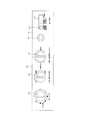
さて、給水先切替用の第4の操作つまみ39について、図5、図6も参照して述べる。第4の操作つまみ39は、図5に示すように、上方に凸となるつまみ部39aを有する凸型をなし、操作パネル34の上面のパネル板46と、その下方に位置するベース板47との間に位置して、横方向(左右方向)にスライド操作可能に設けられている。前記パネル板46には、横長の開口部46aが形成されており、第4の操作つまみ39のつまみ部39aがその開口部46aを通して上方に突出位置している。   Now, the fourth operation knob 39 for switching the water supply destination will be described with reference to FIGS. As shown in FIG. 5, the fourth operation knob 39 has a convex shape having a knob portion 39 a that protrudes upward, and includes a panel plate 46 on the upper surface of the operation panel 34 and a base plate 47 positioned below the operation panel 34. And is provided so as to be slidable in the horizontal direction (left-right direction). The panel plate 46 is formed with a horizontally long opening 46a, and the knob 39a of the fourth operation knob 39 projects upward through the opening 46a.

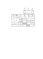
このとき、図6にも示すように、第4の操作つまみ39は、つまみ部39aが開口部46aの一端側(左端側)に位置する第1の位置(図5(a)参照)と、つまみ部39aが開口部46aの中間に位置する第2の位置(図5(b)参照)と、つまみ部39aが開口部46aの他端側(右端側)に位置する第3の位置(図5(c)参照)との3つの位置間で移動操作可能に設けられている。この場合、第4の操作つまみ39は、図示しない節度機構によりそれら3つの位置のいずれかに保持されるようになっており、ユーザが、つまみ部39aを摘んでその保持力に抗する操作力を加えることによって、移動(変位)するようになっている。   At this time, as shown in FIG. 6, the fourth operation knob 39 includes a first position (see FIG. 5A) where the knob portion 39 a is located on one end side (left end side) of the opening 46 a. A second position (see FIG. 5B) where the knob 39a is located in the middle of the opening 46a, and a third position where the knob 39a is located on the other end side (right end side) of the opening 46a (see FIG. 5). 5 (c)), and can be moved between the three positions. In this case, the fourth operation knob 39 is held at any one of these three positions by a moderation mechanism (not shown), and the user grips the knob portion 39a to operate against the holding force. Is added to move (displace).

また、詳しく図示はしないが、第4の操作つまみ39は、連結部材を介して前記給水切替部材42に連結されている。これにて、図6に表形式で示すように、第4の操作つまみ39の第1の位置において、給水切替部材42が左位置に位置され、第4の操作つまみ39の第2の位置において、給水切替部材42が中位置に位置され、第4の操作つまみ39の第3の位置において、給水切替部材42が右位置に位置される。これにより、給水切替機構40は、第4の操作つまみ39が手動操作されることにより、洗濯槽4への給水と、脱水槽5への給水とを切替えるように構成されている。   Although not shown in detail, the fourth operation knob 39 is connected to the water supply switching member 42 through a connecting member. Thus, as shown in a table form in FIG. 6, the water supply switching member 42 is positioned at the left position at the first position of the fourth operation knob 39, and at the second position of the fourth operation knob 39. The water supply switching member 42 is positioned at the middle position, and the water supply switching member 42 is positioned at the right position at the third position of the fourth operation knob 39. Thereby, the water supply switching mechanism 40 is configured to switch between water supply to the washing tub 4 and water supply to the dehydration tub 5 by manually operating the fourth operation knob 39.

更に、図5に示すように、前記ベース板47には、第4の操作つまみ39の第2の位置の真下方向に延びるように、筒部47aが一体に設けられている。そして、前記脱水槽側排水弁18を開閉するためのワイヤ23の上端部は、前記筒部47aを通って第4の操作つまみ39に連結されている。これにて、図5(b)に示すように、第4の操作つまみ39の第2の位置では、ワイヤ23は上方に引張られることはなく、前記脱水槽側排水弁18が閉塞状態となる。これに対し、図5(a)に示す第4の操作つまみ39の第1の位置、及び図5(c)に示す第4の操作つまみ39の第3の位置では、ワイヤ23が筒部47aの上端部の縁部で折曲げられるようにして上方に引張られ、脱水槽側排水弁18が開放状態とされる。   Further, as shown in FIG. 5, a cylindrical portion 47 a is integrally provided on the base plate 47 so as to extend right below the second position of the fourth operation knob 39. And the upper end part of the wire 23 for opening and closing the said dewatering tank side drain valve 18 is connected with the 4th operation knob 39 through the said cylinder part 47a. As a result, as shown in FIG. 5B, at the second position of the fourth operation knob 39, the wire 23 is not pulled upward, and the dewatering tank side drain valve 18 is closed. . On the other hand, in the first position of the fourth operation knob 39 shown in FIG. 5A and the third position of the fourth operation knob 39 shown in FIG. The dewatering tank side drain valve 18 is opened by being pulled upward so as to be bent at the edge of the upper end portion.

以上の構成により、第4の操作つまみ39による脱水槽5側への給水切替えと連動して、脱水槽側排水弁18を閉塞させる脱水槽側排水弁切替機構が構成されるのである。本実施形態では、第4の操作つまみ39は、脱水槽5側への給水切替状態において、第2の位置と第3の位置との2段階に操作可能に設けられ、脱水槽側排水弁切替機構は、そのうちの一方(第4の操作つまみ39の第2の位置)で、脱水槽側排水弁18を閉塞し、他方(第4の操作つまみ39の第3の位置)で、脱水槽側排水弁18を開放するように構成されている。また、本実施形態では、第4の操作つまみ39をスライド変位させる位置によって、給水切替機構40による給水位置(洗濯槽4か脱水槽5か)が切替えられる。   With the above configuration, a dehydrating tank side drain valve switching mechanism for closing the dehydrating tank side drain valve 18 is configured in conjunction with the switching of water supply to the dehydrating tank 5 side by the fourth operation knob 39. In the present embodiment, the fourth operation knob 39 is provided so as to be operable in two stages of the second position and the third position in the water supply switching state to the dewatering tank 5 side. One of them (the second position of the fourth operation knob 39) closes the dewatering tank side drain valve 18, and the other (the third position of the fourth operation knob 39) closes the dehydration tank side. The drain valve 18 is configured to be opened. In the present embodiment, the water supply position (whether the washing tub 4 or the dehydration tub 5) is switched by the position where the fourth operation knob 39 is slid and displaced.

次に、上記構成の二槽式洗濯機1の作用について、図6も参照しながら述べる。上記した二槽式洗濯機1においては、操作パネル34の第4の操作つまみ39の位置によって、給水可能な槽と、脱水槽側排水弁18の開閉とが、図6に表形式で示すように切替えられる。   Next, the operation of the two-tub washing machine 1 configured as described above will be described with reference to FIG. In the above-described two-tank washing machine 1, depending on the position of the fourth operation knob 39 of the operation panel 34, the water supplyable tank and the opening / closing of the dewatering tank side drain valve 18 are shown in a table form in FIG. 6. It is switched to.

即ち、第4の操作つまみ39の第1の位置(左端側)では、給水切替部材22が左位置に位置され、給水切替機構40の給水位置(給水方向)が洗濯槽4側になる。このときには、図5(a)に示すように、ワイヤ23が引張られて脱水槽側排水弁18は開放状態となる。これにて、洗濯槽4側への給水により水を溜めて洗いやすすぎの行程を行うことができる。これと共に、脱水槽5側では、そのまま排水が行われるので、通常の脱水行程を行うことができる。   That is, at the first position (left end side) of the fourth operation knob 39, the water supply switching member 22 is positioned at the left position, and the water supply position (water supply direction) of the water supply switching mechanism 40 is on the washing tub 4 side. At this time, as shown in FIG. 5A, the wire 23 is pulled and the dewatering tank side drain valve 18 is opened. Thus, it is possible to perform a process of storing water by supplying water to the washing tub 4 and rinsing it easily. At the same time, since the drainage is performed as it is on the dehydration tank 5 side, a normal dehydration process can be performed.

これに対し、第4の操作つまみ39を、スライド操作により中間の第2の位置に移動(変位)させると、給水切替部材22が中位置に移動され、給水切替機構40の給水位置(給水方向)が脱水槽5側になる。このときには、図5(b)に示すように、ワイヤ23の引張り力が解除され、脱水槽側排水弁18は閉塞状態となる。これにて、脱水槽5側への給水及び貯水が可能となり、脱水槽5内に水(洗濯液)を溜めることができる。従って、脱水槽5側で、洗いやすすぎ(ためすすぎ)の行程を行うことが可能となる。尚、このとき、溢水口の水位を越えた水は、溢水ホースを通して外部に排出される。   On the other hand, when the fourth operation knob 39 is moved (displaced) to the intermediate second position by the slide operation, the water supply switching member 22 is moved to the middle position, and the water supply position (water supply direction) of the water supply switching mechanism 40 is moved. ) Becomes the dehydration tank 5 side. At this time, as shown in FIG. 5B, the pulling force of the wire 23 is released, and the dewatering tank side drain valve 18 is closed. As a result, water can be supplied to and stored in the dehydration tank 5, and water (washing liquid) can be stored in the dehydration tank 5. Therefore, it is possible to perform a process of rinsing and rinsing on the dehydration tank 5 side. At this time, water exceeding the water level at the overflow outlet is discharged to the outside through the overflow hose.

更に、第4の操作つまみ39を、右端部の第3の位置に移動(変位)させると、給水切替部材22が右位置に移動され、給水切替機構40の給水位置(給水方向)は脱水槽5側のままとなる。このときには、図5(c)に示すように、ワイヤ23が引張られて脱水槽側排水弁18は開放状態となる。これにて、脱水槽5側への給水が可能となるが、脱水槽5内の水はそのまま排水口16から排出される。従って、この状態では、脱水槽5で注水脱水行程を行う(洗濯物に水をかけながら遠心脱水を行う)ことが可能となる。   Further, when the fourth operation knob 39 is moved (displaced) to the third position at the right end, the water supply switching member 22 is moved to the right position, and the water supply position (water supply direction) of the water supply switching mechanism 40 is the dehydration tank. It remains on the 5th side. At this time, as shown in FIG.5 (c), the wire 23 is pulled and the dewatering tank side drain valve 18 will be in an open state. Thus, water can be supplied to the dewatering tank 5 side, but the water in the dewatering tank 5 is discharged as it is from the drain port 16. Therefore, in this state, it is possible to perform the water injection and dehydration process in the dewatering tank 5 (perform the centrifugal dewatering while applying water to the laundry).

上記した二槽式洗濯機1においては、まず、従来から行われている通常の(一般的な)洗濯運転、つまり、洗濯槽4で洗いやすすぎの行程を行い、その後、洗濯物を洗濯槽4から脱水槽5(脱水かご8)に移し替えて脱水の行程を行うといった洗濯運転を行うことができる。この一般的な洗濯運転では、ユーザは、操作パネル34の第4の操作つまみ39を、左側の第1の位置(洗濯槽4への給水側)に操作しておく。脱水槽側排水弁18は開放状態となる。   In the two-tank washing machine 1 described above, first, a normal (general) washing operation that has been conventionally performed, that is, a washing rinsing process in the washing tub 4 is performed, and then the laundry is washed in the washing tub. It is possible to carry out a washing operation in which the dehydration process is carried out by transferring from 4 to the dehydration tank 5 (dehydration basket 8). In this general washing operation, the user operates the fourth operation knob 39 of the operation panel 34 to the first position on the left side (the water supply side to the washing tub 4). The dewatering tank side drain valve 18 is opened.

ユーザは、洗濯槽4の所望の水位まで給水を行った上で、洗濯槽4内に洗濯物や必要な洗剤等を投入する。そして、第2の操作つまみ36を操作して水流強さ(「強」又は「標準」)を選択し、更に第1の操作つまみ35を操作して洗いタイマーを動作させる。これにより、洗濯用モータ28によりパルセータ7が駆動され設定された時間の洗い行程(及びすすぎ行程)を行うことができる。行程終了後、ユーザが、第2の操作つまみ36を「排水」に回動操作すると、洗濯槽側排水弁15が開放されて排水口13からの排水が行われる。   The user supplies water up to a desired water level in the washing tub 4 and then puts laundry or necessary detergent into the washing tub 4. Then, the second operation knob 36 is operated to select the water flow strength (“strong” or “standard”), and the first operation knob 35 is further operated to operate the washing timer. As a result, the pulsator 7 is driven by the washing motor 28 and the washing process (and the rinsing process) for the set time can be performed. When the user turns the second operation knob 36 to “drainage” after the end of the process, the washing tub-side drain valve 15 is opened and drainage from the drain port 13 is performed.

一方、脱水槽5においては、脱水の行程を行うことができる。この脱水の行程は、第4の操作つまみ39が第1の位置(洗濯槽4への給水側)にあって、脱水槽側排水弁18の開放状態で行われる。ユーザは、洗濯物を脱水かご8に入れた(洗濯槽4から移し替えた)状態で、第3の操作つまみ37を右回り方向に回動操作することにより、脱水かご8を一方向に高速回転させる脱水運転が行われる。脱水槽側排水弁18は開放状態にあるので、洗濯物から出た水は排水口13からそのまま排出される。   On the other hand, in the dehydration tank 5, a dehydration process can be performed. This dehydration process is performed when the fourth operation knob 39 is at the first position (water supply side to the washing tub 4) and the dewatering tub side drain valve 18 is open. In a state where the laundry is put in the dehydration basket 8 (transferred from the washing tub 4), the user rotates the third operation knob 37 in the clockwise direction to move the dehydration basket 8 in one direction at high speed. A spin-drying operation is performed. Since the dewatering tank side drain valve 18 is in an open state, the water discharged from the laundry is discharged from the drain port 13 as it is.

また、本実施形態では、脱水槽5において、洗濯運転(脱水かご8内の洗濯物に対する洗い行程やすすぎ行程)を行うことができる。この脱水槽側洗濯運転を行うにあたっては、ユーザは、第4の操作つまみ39を、第2の位置に操作しておく。これにより、脱水槽側排水弁18が閉塞状態となり、水道の蛇口を開放させて給水を行うことにより、脱水槽5内に任意の水位で水(洗濯水)を溜めることができる。   In the present embodiment, the dehydration tank 5 can perform a washing operation (a washing process or an excessive process for the laundry in the dehydration basket 8). In performing the dewatering tub side washing operation, the user operates the fourth operation knob 39 to the second position. Thereby, the dewatering tank side drain valve 18 is closed, and water (washing water) can be stored in the dewatering tank 5 at an arbitrary water level by opening the tap and supplying water.

この後、ユーザが、第3の操作つまみ37を左回り方向に、所望の時間(例えば10分)の位置まで回動操作することにより、脱水槽5側での洗いの行程(又はすすぎの行程)が実行される。この脱水槽5側での洗濯運転では、上記のように、脱水用モータ11の3秒オン(正転)、9秒オフ、3秒オン(逆転)、9秒オフを繰返すことにより行われる。脱水用モータ11のオン時には、脱水かご8が回転され、脱水用モータ11のオフ時に、脱水かご8は減速しながら惰性回転する。脱水かご8が停止する前に、脱水用モータ11の次のオンがなされ、脱水かご8が逆方向に回転する。   Thereafter, the user rotates the third operation knob 37 in the counterclockwise direction to a position for a desired time (for example, 10 minutes), so that the washing process (or the rinsing process) on the dehydration tank 5 side is performed. ) Is executed. In the washing operation on the side of the dewatering tank 5, as described above, the dewatering motor 11 is repeatedly turned on for 3 seconds (forward rotation), off for 9 seconds, on (reverse rotation) for 3 seconds, and off for 9 seconds. When the dehydrating motor 11 is on, the dewatering basket 8 is rotated. When the dehydrating motor 11 is off, the dehydrating basket 8 rotates by inertia while decelerating. Before the dehydration basket 8 stops, the dehydration motor 11 is turned on next, and the dehydration basket 8 rotates in the reverse direction.

この洗い行程により、脱水かご8内に収容された洗濯物に対して、洗剤を含んだ洗濯水が、例えば回転に伴う遠心力により内周側から外周側に向けて緩やかに相対的に通過した後、洗濯水が脱水かご8内に戻ることが繰返され、洗濯物の汚れが落とされていく。洗い行程が終了すると、ユーザは、第4の操作つまみ39を第3の位置(又は第1の位置)に切替え操作する。すると、脱水槽側排水弁18が開放し、排水口16から排水が行われるようになる。脱水槽5側でのすすぎ行程も同様に行うことができる。   By this washing process, the washing water containing the detergent passed relatively slowly from the inner peripheral side to the outer peripheral side by centrifugal force accompanying rotation, for example, with respect to the laundry stored in the dewatered basket 8. Thereafter, the washing water is repeatedly returned into the dehydration basket 8 and the laundry is cleaned. When the washing process ends, the user switches the fourth operation knob 39 to the third position (or the first position). Then, the dewatering tank side drain valve 18 is opened, and drainage is performed from the drain port 16. The rinsing process on the side of the dehydration tank 5 can be performed in the same manner.

また、洗い行程の後、第4の操作つまみ39を第3の位置(又は第1の位置)に切替え操作して排水を行った後、第3の操作つまみ37を右回り方向に回動操作することにより、中間脱水を行うこともできる。所定時間の中間脱水を行った後、第4の操作つまみ39を第2の位置に切替え操作し、給水を行った上ですすぎ行程を実施し、その後、排水を行った上で脱水行程を行うことができる。以上の構成を全て脱水槽5(脱水かご8)側で行うことにより、洗濯物を途中で移し替えることなく済ませることができる。   In addition, after the washing process, the fourth operation knob 39 is switched to the third position (or the first position) to perform drainage, and then the third operation knob 37 is rotated clockwise. By doing so, intermediate dehydration can also be performed. After performing the intermediate dehydration for a predetermined time, the fourth operation knob 39 is switched to the second position, the water supply is performed, the rinsing process is performed, and then the drainage is performed and the dehydration process is performed. be able to. By performing all of the above configuration on the side of the dehydration tank 5 (dehydration basket 8), the laundry can be completed without being transferred on the way.

或いは、洗濯槽4内で洗濯物の洗い行程を実施した後、洗濯槽4の排水を行うことなく、洗濯物だけを脱水槽5(脱水かご8)に移し替え、脱水槽5側ですすぎ(中間脱水を含む)及び脱水の行程を行うことができる。この場合、洗濯槽4内に残っている洗濯液を使用(二度使い)して、別の洗濯物の洗い行程を行うことができる。このとき、脱水槽5側でのすすぎ行程と同時に並行して洗濯槽4側での洗い行程を行うこともできる。これにより、洗濯液(水)の有効利用を図ることができる。また、2回の洗濯に要する時間の短縮化も図ることができる。   Alternatively, after washing the laundry in the washing tub 4, without washing the washing tub 4, only the laundry is transferred to the dehydration tub 5 (dehydration basket 8) and rinsed on the dehydration tub 5 side ( Intermediate dehydration) and dehydration steps can be performed. In this case, the washing liquid remaining in the washing tub 4 can be used (used twice) to perform another washing process of the laundry. At this time, the washing process on the washing tub 4 side can be performed in parallel with the rinsing process on the dehydration tub 5 side. Thereby, the effective utilization of a washing liquid (water) can be aimed at. In addition, the time required for two washings can be shortened.

更に、本実施形態では、脱水槽5側で、注水脱水を行うこともできる。この注水脱水を行うにあたっては、第4の操作つまみ39を第3の位置に切替え操作する。これにより、給水位置を脱水槽5側としながら、脱水槽側排水弁18が開放する。ユーザは、第3の操作つまみ37を右回り方向に回動操作して脱水かご5を高速回転させると共に、水道の蛇口を開いて脱水槽5(脱水かご8)内の洗濯物に対し注水をすることにより、所望の時間の注水脱水を行うことができる。   Furthermore, in this embodiment, water injection and dewatering can also be performed on the dewatering tank 5 side. In performing this water injection and dehydration, the fourth operation knob 39 is switched to the third position. Thereby, the dewatering tank side drain valve 18 is opened while the water supply position is on the dewatering tank 5 side. The user rotates the third operation knob 37 in the clockwise direction to rotate the dewatering basket 5 at a high speed, and opens the water tap to inject water into the laundry in the dewatering tub 5 (dehydrated basket 8). By doing so, water injection and dehydration can be performed for a desired time.

このように本実施形態の二槽式洗濯機1によれば、次のような効果を得ることができる。即ち、本実施形態では、第4の操作つまみ39の手動操作に基づき、給水切替機構40により給水口38からの洗濯槽4への給水と脱水槽5への給水とを切替えることができるので、ユーザは、脱水槽側排水弁18の閉塞状態で、脱水槽5への給水を行い、脱水槽5内に洗濯水を溜めることができる。そして、第3の操作つまみ37を左回り方向に操作することにより、脱水槽5側での洗濯運転(洗い、すすぎの行程)を実行させることができる。   Thus, according to the two-tub type washing machine 1 of the present embodiment, the following effects can be obtained. That is, in this embodiment, based on the manual operation of the fourth operation knob 39, the water supply switching mechanism 40 can switch between water supply to the washing tub 4 and water supply to the dehydration tub 5 from the water supply port 38. The user can supply water to the dewatering tank 5 while the dewatering tank side drain valve 18 is closed, and can store washing water in the dewatering tank 5. Then, by operating the third operation knob 37 in the counterclockwise direction, the washing operation (washing and rinsing process) on the dehydrating tub 5 side can be executed.

これにより、脱水槽5側での洗い行程を行った後(或いは洗濯槽4で洗い行程を行った後)、脱水かご8内に洗濯物を収容した状態で、中間脱水行程、すすぎ行程を行うことができ、更に、最終脱水の行程を行うことができる。つまり、脱水槽5を利用して、洗濯の各行程を、洗濯物の移し替えを極力少なくしながら、或いは水の使用量を少なくしながら進めていくことができる。   As a result, after the washing process at the dehydration tub 5 side (or after the washing process at the washing tub 4), the intermediate dehydration process and the rinsing process are performed with the laundry stored in the dehydration basket 8. In addition, a final dehydration process can be performed. That is, by using the dehydrating tank 5, each washing process can be performed while minimizing the transfer of the laundry or reducing the amount of water used.

このとき、給水切替機構40の第4の操作つまみ39を第2の位置に操作することにより、脱水槽5側への給水位置の切替えと連動して、脱水槽側排水弁18が閉塞されるので、それらを別々に操作する場合と比べて、操作が簡単となる。そして、脱水槽側排水弁18に関して、機械的に動作する排水弁18を採用することができる。また、給水弁を設けることもなく済ませることができる。従って、本実施形態では、電気的に動作する給水弁、排水弁をコンピュータにより制御したりするいわば半自動の二槽式洗濯機とは異なり、手動操作に基づいて洗濯の各行程を進めることができ、比較的簡単な構成で安価に済ませることができる。   At this time, by operating the fourth operation knob 39 of the water supply switching mechanism 40 to the second position, the dewatering tank side drain valve 18 is closed in conjunction with the switching of the water supply position to the dewatering tank 5 side. Therefore, operation becomes simple compared with the case of operating them separately. And regarding the dewatering tank side drain valve 18, a mechanically operated drain valve 18 can be employed. Moreover, it can complete without providing a water supply valve. Therefore, in this embodiment, unlike the so-called semi-automatic two-tub washing machine in which electrically operated water supply and drain valves are controlled by a computer, each washing process can be performed based on manual operation. It can be made inexpensively with a relatively simple configuration.

特に本実施形態では、第4の操作つまみ39を第3の位置に操作することにより、給水切替機構40による給水位置を脱水槽5側にした状態でありながら、脱水槽側排水弁18を開放することができるように構成した。これにより、脱水槽5側での洗いやためすすぎの行程に加えて、第4の操作つまみ39を第3の位置に操作することによって、脱水槽5側で注水脱水の行程を実施することも可能となった。   In particular, in the present embodiment, the dehydration tank side drain valve 18 is opened while the water supply position by the water supply switching mechanism 40 is set to the dehydration tank 5 side by operating the fourth operation knob 39 to the third position. Configured to be able to. Thus, in addition to the washing and rinsing process on the dehydration tank 5 side, the water injection / dehydration process may be performed on the dehydration tank 5 side by operating the fourth operation knob 39 to the third position. It has become possible.

またこのとき、第4の操作つまみ39は、一端(左端)側の第1の位置と、中間の第2の位置と、他端(右端)側の第3の位置との間で移動操作可能に構成したので、第4の操作つまみ39の移動に、脱水槽側排水弁18のワイヤ23を連動させ、第4の操作つまみ39の第2の位置で、ワイヤ23の引張り力の解除状態、第4の操作つまみ39の第1の位置及び第3の位置で、ワイヤ23の引張り状態とするような構造を、容易に実現することができる。脱水槽側排水弁18を閉塞状態から開放に切替える際、つまり第4の操作つまみ39を、第2の位置から、第1の位置と第3の位置とに移動操作する際の、第4の操作つまみ39の操作力の均一化も図ることができる。   At this time, the fourth operation knob 39 can be moved between a first position on one end (left end) side, a second position in the middle, and a third position on the other end (right end) side. Since the wire 23 of the dewatering tank side drain valve 18 is interlocked with the movement of the fourth operation knob 39, the tensile force of the wire 23 is released at the second position of the fourth operation knob 39, A structure in which the wire 23 is pulled at the first position and the third position of the fourth operation knob 39 can be easily realized. When the dewatering tank side drain valve 18 is switched from the closed state to the open state, that is, the fourth operation knob 39 is moved from the second position to the first position and the third position. The operating force of the operation knob 39 can be made uniform.

更に本実施形態では、給水切替機構40についても、給水の位置を切替えるための給水切替部材42を、左右(洗濯槽4と脱水槽5との並び方向)に移動可能に構成し、給水切替部材42を第4の操作つまみ39と連動させる構成とした。これにより、給水切替機構40を簡単な構成で済ませることができる。また、第4の操作つまみ39をスライド式としたことにより、給水切替機構40による給水位置の切替えに連動して、脱水槽側排水弁18が開閉する構造を、容易に実現することができた。   Further, in the present embodiment, also in the water supply switching mechanism 40, the water supply switching member 42 for switching the water supply position is configured to be movable left and right (in the direction in which the washing tub 4 and the dewatering tub 5 are arranged), and the water supply switching member 42 is interlocked with the fourth operation knob 39. Thereby, the water supply switching mechanism 40 can be completed with a simple configuration. In addition, since the fourth operation knob 39 is slidable, it is possible to easily realize a structure in which the dewatering tank side drain valve 18 opens and closes in conjunction with the switching of the water supply position by the water supply switching mechanism 40. .

尚、二槽式洗濯機は、上記した各実施形態に限定されるものではなく、例えば、次のような拡張、変更が可能である。即ち、上記実施形態では、洗濯槽側排水弁15として、脱水槽側排水弁18と同様にワイヤ24により機械的に開閉動作する構成のものを採用したが、ソレノイドやモータ等により、電気的に動作する弁を採用しても良い。この場合、操作パネルに、スイッチを設け、ユーザがそのスイッチの手動操作を行うことにより、洗濯槽側排水弁の開閉が行われる構成とすることができる。また、給水切替機構についても、2つの電気的に動作する給水弁を設けて、洗濯槽4側、脱水槽5側に夫々給水を行う構成としても良い。   In addition, a two-tub washing machine is not limited to each above-mentioned embodiment, For example, the following expansion and change are possible. That is, in the above embodiment, the washing tub side drain valve 15 is configured to be mechanically opened and closed by the wire 24 similarly to the dewatering tub side drain valve 18. An operating valve may be employed. In this case, a switch can be provided on the operation panel, and the user can manually open and close the washing tub-side drain valve. In addition, the water supply switching mechanism may be configured such that two electrically operated water supply valves are provided to supply water to the washing tub 4 side and the dewatering tub 5 side, respectively.

また、上記実施形態では、脱水槽洗濯運転時に、脱水用モータ11を間欠的に正逆方向に交互に駆動するように構成したが、一方向に間欠駆動することも可能である。脱水用モータ11のオン・オフの時限についても、一例を示したに過ぎず、様々な変更が可能であることは勿論である。更に、上記実施形態では、脱水・脱水槽洗いタイマー20用の操作つまみ37を設けるようにしたが、脱水槽洗濯運転用のタイマー(操作つまみ)を、脱水運転用のタイマー(操作つまみ)とは別に設けても良い。その他、要旨を逸脱しない範囲内で適宜変更して実施し得る。   In the above embodiment, the dehydration motor 11 is intermittently driven alternately in the forward and reverse directions during the dewatering tub washing operation, but can be intermittently driven in one direction. The on / off time limit of the dehydrating motor 11 is merely an example, and it goes without saying that various changes can be made. Furthermore, in the above embodiment, the operation knob 37 for the dehydration / dehydration tub washing timer 20 is provided. However, the timer (operation knob) for the dehydration tub washing operation is referred to as the dehydration operation timer (operation knob). It may be provided separately. In addition, the present invention can be implemented with appropriate modifications without departing from the scope of the invention.

図面中、1は二槽式洗濯機、4は洗濯槽、5は脱水槽、8は脱水かご、17は脱水側排水管路(排水路)、18は脱水槽側排水弁、23はワイヤ、34は操作パネル(操作部)、38は給水口、39は第4の操作つまみ、40は給水切替機構、42は給水切替部材を示す。   In the drawings, 1 is a two-tub washing machine, 4 is a washing tub, 5 is a dewatering tub, 8 is a dewatering basket, 17 is a dewatering side drain pipe (drainage channel), 18 is a dewatering tub side drain valve, 23 is a wire, Reference numeral 34 denotes an operation panel (operation unit), 38 denotes a water supply port, 39 denotes a fourth operation knob, 40 denotes a water supply switching mechanism, and 42 denotes a water supply switching member.

Claims (4)

洗濯槽と、脱水かごを有する脱水槽とを備え、洗い、すすぎ、脱水からなる洗濯運転を手動操作に基づいて実施する二槽式洗濯機において、
前記脱水槽の排水路を開閉する脱水槽側排水弁と、
操作部に設けられた操作つまみの手動操作により給水口からの前記洗濯槽への給水と前記脱水槽への給水とを切替える給水切替機構と、
前記給水切替機構の操作つまみによる前記脱水槽側への給水切替えと連動して、前記脱水槽側排水弁を閉塞させる脱水槽側排水弁切替機構とを具備することを特徴とする二槽式洗濯機。
In a two-tank washing machine comprising a washing tub and a dehydration tub having a dehydration basket and performing a washing operation consisting of washing, rinsing and dehydration based on manual operation,
A dewatering tank side drain valve for opening and closing the drainage channel of the dewatering tank;
A water supply switching mechanism that switches between water supply to the washing tub from the water supply port and water supply to the dehydration tub by manual operation of an operation knob provided in the operation unit;
A two-tub laundry having a dewatering tank-side drain valve switching mechanism that closes the dewatering tank-side drain valve in conjunction with switching of water supply to the dehydrating tank side by an operation knob of the water supply switching mechanism Machine.
前記操作つまみは、前記脱水槽側への給水切替状態において、2段階に操作可能に設けられ、
前記脱水槽側排水弁切替機構は、前記操作つまみの前記2段階の操作のうちの一方で、前記脱水槽側排水弁を閉塞し、他方で前記脱水槽側排水弁を開放するように構成されていることを特徴とする請求項1記載の二槽式洗濯機。
The operation knob is provided to be operable in two stages in the water supply switching state to the dehydration tank side,
The dehydrating tank side drain valve switching mechanism is configured to close the dehydrating tank side drain valve and open the dehydrating tank side drain valve on one side of the two-stage operations of the operation knob. The two-tub type washing machine according to claim 1, wherein
前記操作つまみは、一端側の第1の位置と、中間の第2の位置と、他端側の第3の位置との間で移動操作可能に設けられ、
前記操作つまみの前記第1の位置では前記洗濯槽への給水が可能となり、前記第2の位置では前記脱水槽側への給水が可能となると共に前記脱水槽側排水弁が閉塞し、前記第3の位置では前記脱水槽側への給水が可能となると共に前記脱水槽側排水弁が開放するように構成されていることを特徴とする請求項2記載の二槽式洗濯機。
The operation knob is provided so as to be movable between a first position on one end side, a second position in the middle, and a third position on the other end side,
In the first position of the operation knob, water can be supplied to the washing tub, and in the second position, water can be supplied to the dewatering tub side, and the dewatering tub side drain valve is closed. 3. The two-tank washing machine according to claim 2, wherein water is supplied to the dewatering tank side at the position 3 and the dewatering tank side drain valve is opened.
前記操作つまみはスライド式であり、スライド変位する位置によって前記給水切替機構による給水位置又は方向が変更されると共に、前記脱水槽側排水弁を開閉操作するように構成されていることを特徴とする請求項1から3のいずれか一項に記載の二槽式洗濯機。   The operation knob is a slide type, and a water supply position or direction by the water supply switching mechanism is changed according to a slide displacement position, and the dewatering tank side drain valve is opened and closed. The two-tank type washing machine according to any one of claims 1 to 3.
JP2015091501A 2015-04-28 2015-04-28 Twin tub washing machine Pending JP2016202808A (en)

Priority Applications (1)

Application Number Priority Date Filing Date Title
JP2015091501A JP2016202808A (en) 2015-04-28 2015-04-28 Twin tub washing machine

Applications Claiming Priority (1)

Application Number Priority Date Filing Date Title
JP2015091501A JP2016202808A (en) 2015-04-28 2015-04-28 Twin tub washing machine

Publications (1)

Publication Number Publication Date
JP2016202808A true JP2016202808A (en) 2016-12-08

Family

ID=57488135

Family Applications (1)

Application Number Title Priority Date Filing Date
JP2015091501A Pending JP2016202808A (en) 2015-04-28 2015-04-28 Twin tub washing machine

Country Status (1)

Country Link
JP (1) JP2016202808A (en)

Cited By (1)

* Cited by examiner, † Cited by third party
Publication number Priority date Publication date Assignee Title
CN115478416A (en) * 2021-06-15 2022-12-16 青岛海尔洗衣机有限公司 Centrifugal drainage device and washing machine

Cited By (1)

* Cited by examiner, † Cited by third party
Publication number Priority date Publication date Assignee Title
CN115478416A (en) * 2021-06-15 2022-12-16 青岛海尔洗衣机有限公司 Centrifugal drainage device and washing machine

Similar Documents

Publication Publication Date Title
KR20100119451A (en) Washing machine and method to control thereof
US10995447B2 (en) Laundry treating appliance detergent dispenser
US11692294B2 (en) Laundry treating appliance detergent dispenser
KR100985069B1 (en) washer
JP2016202808A (en) Twin tub washing machine
JP2014094074A (en) Twin tub washing machine
JP2016059599A (en) Twin tub type washing machine
JP4561594B2 (en) Washing machine
JP2016154727A (en) Two tank washing machine
KR100319696B1 (en) hand washing machine of one tube
CN112218567B (en) A tub and a cleaning system comprising such a tub
KR20000009640A (en) Control method of washing machine
JPS5929669Y2 (en) dehydrator
JPH1015275A (en) Two-tub washing machine
KR101669489B1 (en) Valve for changing flow paths and Washing machine including the valve
JPH0221017Y2 (en)
KR101123304B1 (en) Method for controlling a clutch of washing machine
JP3050803U (en) Electric washing machine
JPS633636B2 (en)
JPS6014459Y2 (en) automatic washing machine
KR0125469Y1 (en) Water supplying apparatus for a washing machine
JP6054090B2 (en) Washing machine
JPH03231700A (en) Washing machine
KR20040110769A (en) Control method of washing machine
JP2007143910A (en) Washing machine