JP2016199266A - Mirror device with display function and display switching method - Google Patents
Mirror device with display function and display switching method Download PDFInfo
- Publication number
- JP2016199266A JP2016199266A JP2016142164A JP2016142164A JP2016199266A JP 2016199266 A JP2016199266 A JP 2016199266A JP 2016142164 A JP2016142164 A JP 2016142164A JP 2016142164 A JP2016142164 A JP 2016142164A JP 2016199266 A JP2016199266 A JP 2016199266A
- Authority
- JP
- Japan
- Prior art keywords
- display
- range
- mirror
- motion
- control unit
- Prior art date
- Legal status (The legal status is an assumption and is not a legal conclusion. Google has not performed a legal analysis and makes no representation as to the accuracy of the status listed.)
- Granted
Links
Images


Abstract
Description
本発明は、反射機能を有するとともに、画像表示機能を併せ持つ表示機能付きミラー装置および表示切替方法に関する。 The present invention relates to a mirror device with a display function having a reflection function and an image display function, and a display switching method.
自動車の車室内に取り付けられるルームミラーに、表示機能を備えるものが提案されている。表示機能には、自動車の後方を撮影するカメラの映像が表示される。 A room mirror that is attached to the interior of an automobile is provided with a display function. The display function displays an image of a camera that captures the rear of the car.
特許文献1には、ハーフミラーの裏面にモニター装置を備え、複数のカメラ映像を同時に表示するルームミラーが開示されている。また、特許文献2には、撮影画像の表示サイズを変更するルームミラーが開示されている。
ハーフミラーを用いた表示機能付きルームミラーである場合、ハーフミラーによる反射機能と、ハーフミラーを介して液晶表示パネル等の表示映像を表示する表示機能とがあり、ユーザの目的に応じて切り替える必要もある。また、通常のルームミラーとは異なり、カメラが撮影した画像の切り取り範囲の設定により、表示機能付きルームミラーに表示する範囲を変更することができる。 In the case of a room mirror with a display function using a half mirror, there are a reflection function by the half mirror and a display function for displaying a display image such as a liquid crystal display panel through the half mirror, and it is necessary to switch according to the purpose of the user There is also. In addition, unlike a normal room mirror, the range displayed on the room mirror with a display function can be changed by setting the cutout range of an image taken by the camera.
表示機能付きルームミラーの機能の切り替えや、表示範囲の操作は、自動車の運転中に行うことが多く、安全性を損なわないことが求められる。このため、これらの操作が各々独立した操作系統ではなく、一元化した操作系統であることが望ましい。さらには、ユーザが運転中に直感的に操作可能であり、且つ操作の誤認が無いことが望ましい。 Switching the function of the room mirror with a display function and the operation of the display range are often performed during driving of the automobile, and it is required that safety is not impaired. For this reason, it is desirable that these operations are not an independent operation system but a unified operation system. Furthermore, it is desirable that the user can operate intuitively while driving and there is no misperception of the operation.
本発明は、このような問題を解決するためになされたものであり、機能の切り替えおよび表示範囲の操作を、安全性を損なわずに直感的に行うことができる、表示機能付きミラー装置および表示切替方法を提供することを目的とする。 The present invention has been made to solve such a problem, and a mirror device with a display function and a display capable of intuitively performing function switching and display range operation without impairing safety. An object is to provide a switching method.
上記目的を達成するために、本発明に係る表示機能付きミラー装置は、車両の後方を撮影する撮像装置の映像を表示する表示パネルと、前記表示パネルの表示面に備えられたハーフミラーと、を備える、表示機能付きルームミラーと、モーション検出を行うモーションセンサと、前記表示機能付きルームミラーが、前記表示パネルの表示が停止され前記ハーフミラーのミラー面を用いたルームミラーとして機能しているときは、前記モーションセンサが検出した方向のうちいずれの方向におけるモーション検出結果においても、前記表示パネルの表示を実行させる表示機能へ切り替える処理を行い、前記表示機能付きルームミラーが、前記表示パネルの表示が行われている表示機能を実行しているときは、前記モーションセンサが検出したモーション検出は、各々の方向に対する表示範囲の移動指示として処理する、切替制御部と、前記モーションセンサが検出したモーション検出が、各々の方向に対する表示範囲の移動指示である場合、前記モーションセンサが検出したモーション検出に基づいて、表示範囲を移動させるとともに、表示される範囲の広さを変化させる、表示制御部と、を備えることを特徴とする。 To achieve the above object, a mirror device with a display function according to the present invention includes a display panel that displays an image of an imaging device that captures the back of a vehicle, a half mirror provided on a display surface of the display panel, The display function room mirror, the motion sensor for detecting motion, and the display function room mirror function as a room mirror using the mirror surface of the half mirror with the display of the display panel stopped. When the motion detection results in any of the directions detected by the motion sensor, a process for switching to a display function for executing display on the display panel is performed, and the room mirror with a display function is connected to the display panel. When executing the display function that is being displayed, the mode detected by the motion sensor The motion detection is processed as an instruction to move the display range for each direction. When the motion detection detected by the switching control unit and the motion sensor is an instruction to move the display range for each direction, the motion sensor detects And a display control unit that moves the display range based on the detected motion and changes the width of the displayed range.
また、本発明に係る表示切替方法は、車両の後方を撮影する撮像装置の映像を表示する表示パネルおよび前記表示パネルの表示面に備えられたハーフミラーを備える表示機能付きルームミラーが、前記表示パネルの表示が停止され前記ハーフミラーのミラー面を用いたルームミラーとして機能しているときは、モーション検出を行うモーションセンサが検出した方向のうちいずれの方向におけるモーション検出結果においても、前記表示パネルの表示を実行させる表示機能へ切り替え、前記表示機能付きルームミラーが、前記表示パネルの表示が行われている表示機能を実行しているときは、前記モーションセンサが検出したモーション検出は、各々の方向に対する表示範囲の移動指示を行うとともに、前記モーションセンサが検出したモーション検出に基づいて、表示される範囲の広さを変化させる。 In the display switching method according to the present invention, a display panel that displays an image of an imaging device that captures the rear of a vehicle, and a room mirror with a display function that includes a half mirror provided on a display surface of the display panel, When the display of the panel is stopped and it functions as a room mirror using the mirror surface of the half mirror, the display panel can display the motion detection result in any direction detected by the motion sensor that performs motion detection. When the room mirror with a display function is executing a display function in which the display panel is displayed, the motion detection detected by the motion sensor is In addition to instructing to move the display range with respect to the direction, the mode detected by the motion sensor Based on tio emission detection, to vary the breadth of the range to be displayed.
本実施形態によれば、機能の切り替えおよび表示範囲の操作を、安全性を損なわずに直感的に行うことができる。 According to the present embodiment, it is possible to intuitively perform function switching and display range operation without sacrificing safety.
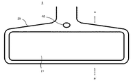
以下、本発明の第1の実施形態について説明する。図1は、本発明の第1の実施形態に係る表示機能付きルームミラー1をユーザである運転者側から見た外観図である。表示機能付きルームミラー1は、通常のルームミラーと同様に、ユーザから見て車両の進行方向であり、一般的にはウィンドシールドの上部などに装着される。
Hereinafter, a first embodiment of the present invention will be described. FIG. 1 is an external view of a
表示機能付きルームミラー1は、ユーザに後方を反射させるミラー面21、ミラー面21を覆い筐体として機能するカバー20、およびユーザの操作を受け付けるセンサであるモーションセンサ40を備える。本実施形態においては、モーションセンサ40は、表示機能付きルームミラー1の中央上部に配置したが、ユーザの操作を目的としたモーションを誤認無く適切に認識可能であれば、配置場所は問わず、表示機能付きルームミラー1とは離れた位置に配置されてもよい。
The
図2は、図1に示す表示機能付きルームミラー1のa-a’の断面図を模式的に示した図である。
FIG. 2 is a view schematically showing a cross-sectional view taken along a-a ′ of the
図2に示すように、ミラー面21はハーフミラー22が構成する面である。また、カバー20の内部には、ハーフミラー22とほぼ同一形状の液晶パネル31およびバックライト32が配置される。液晶パネル31とバックライト32とで、表示パネル30を構成する。表示パネル30は、表示される映像を光の発光により形成する構成であれば、液晶パネル31およびバックライト32の組合せに代えて、有機EL(Electro Luminescence)パネルなどの自発光表示パネルであってもよい。図2では、表示パネル30を駆動するための電源回路などは図示を省略する。
As shown in FIG. 2, the
図1および図2に示す表示機能付きルームミラー1において、表示パネル30による表示が行われていないときは、バックライト32が点灯しない。このとき、ハーフミラー22は、ミラー面21に入射した光の大半を反射する。このため、表示機能付きルームミラー1は、ミラー面21の反射でユーザが後方を確認するミラーモードとして動作する。また、表示機能付きルームミラー1において、表示パネル30による表示が行われているときは、バックライト32が点灯する。このとき、バックライト32によって発せられた光は、液晶パネル31を介してハーフミラー22を透過する。このため、表示機能付きルームミラー1は、表示パネル30が表示する映像を表示する表示モードとして動作する。
In the
図3は、表示機能付きルームミラー1が用いるモーションセンサ40を概念的に示した 図である。モーションセンサ40は、複数のフォトダイオードが組み合わされたセンサであり、4個のフォトダイオードが組み合わせられている場合は、4方向のモーションを検出可能である。モーションセンサ40は、その内部に上方向検出フォトダイオード41U、下方向検出フォトダイオード41D、左方向検出フォトダイオード41L、右方向検出フォトダイオード41Rを備える。これらの各々のフォトダイオードの上下左右は、図1に示すユーザから見た表示機能付きルームミラー1の上下左右と一致して配置される。このようなモーションセンサ40が物体を検出可能な範囲は、モーションセンサ40の前方0.1m〜0.2mである。なお、本実施形態では、説明の便宜上、上下左右の4方向を例に挙げて説明するが、上下左右の4方向は一例であり、これらの4方向に限られるものではなく、また、方向の数についても4つに限られるものではない。
FIG. 3 is a diagram conceptually showing the
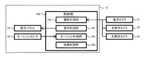
図4は、第1の実施形態に係る表示機能付きミラー装置10の機能ブロック図を示した図である。表示機能付きミラー装置10は、表示機能付きルームミラー1を構成する表示パネル30、モーションセンサ40、および各種データを処理する制御部100から構成される。制御部100は、各種データ処理を行うCPU(Central Processing Unit)やDSP(Digital Signal Processor)、メモリ等によって構成される。制御部100は、表示機能付きルームミラー1に内蔵されていてもよく、ナビゲーション装置や車載コンピュータなどの制御機能を用いてもよい。
FIG. 4 is a functional block diagram of the
制御部100は、その機能に基づき、撮影制御部102、表示制御部104、モーション制御部106、切替制御部108を備える。各々の機能は、単一の装置に搭載される制御機能により実現されてもよく、分散された複数の装置に搭載される制御機能により実現されてもよい。
The
撮影制御部102は、表示機能付きミラー装置10が搭載されている車両の後方が撮影可能となるような向きに搭載されている後方カメラ51が撮影した映像データを取得する。
The
表示制御部104は、撮影制御部102が取得した映像データを、表示パネル30に表示させる処理を行う。具体的には、表示制御部104は、表示パネル30の形状に合わせた映像データの切り取りや、映像の輝度や色調を調整する。
The display control unit 104 performs processing for displaying the video data acquired by the
モーション制御部106は、モーションセンサ40からの出力信号を取得し、モーションの方向等を検出する。モーション制御部106は、モーションセンサ40が備える4個のフォトダイオードの各々が物体を検出した場合の検出波形のピーク値の分布を解析し、モーションセンサ40の前方を、物体が上下左右のいずれの方向に通過したのかを検出する。また、モーション制御部106は、所定時間内に上方向および下方向の物体通過が連続して検出された場合は、物体の上下方向の往復として検出することができる。同様に、モーション制御部106は、所定時間内に左方向および右方向の物体通過が連続して検出された場合は、物体の左右方向の往復として検出することができる。
The motion control unit 106 acquires an output signal from the
モーション制御部106は、モーションを検出すべき期間中は、モーションセンサ40の各々のフォトダイオードからの出力値を常時取得する。モーション制御部106は、上方向検出フォトダイオード41Uの出力値Uout、下方向検出フォトダイオード41Dの出力値Dout、左方向検出フォトダイオード41Lの出力値Lout、右方向検出フォトダイオード41Rの出力値Routを取得する。
The motion control unit 106 always acquires the output value from each photodiode of the
モーション制御部106は、例えば、(Uout−Dout)/(Uout+Dout)、(Rout−Lout)/(Rout+Lout)のピーク波形より、ジェスチャー方向を判断する。また、判断されたモーション方向に対して、例えば1秒〜2秒に設定された所定時間内に反対方向のモーション方向を検出した場合は、往復のモーションであると判断する。 For example, the motion control unit 106 determines the gesture direction from the peak waveforms of (Uout−Dout) / (Uout + Dout) and (Rout−Lout) / (Rout + Lout). For example, when a motion direction opposite to the determined motion direction is detected within a predetermined time set to 1 second to 2 seconds, for example, it is determined that the motion is a reciprocating motion.
切替制御部108は、モーション制御部106の検出結果に基づき、表示制御部104を制御する。具体的には、表示機能付きルームミラー1が、ミラーモードとして動作しているときは、モーション制御部106が検出した4方向のいずれの方向におけるモーション検出結果においても、表示モードへ切り替える制御を行う。ミラーモードから表示モードへの切り替えとは、表示制御部104による表示パネル30に対する制御で、後方カメラ51の映像が表示されていない状態から表示される状態へ切り替えることである。また、表示機能付きルームミラー1が表示モードとして動作しているときは、モーション制御部106が検出した4方向のモーション検出は、検出した方向に対する表示範囲の移動指示として処理される。
The switching
また、切替制御部108は、表示機能付きルームミラー1が、表示モードとして動作しているときは、モーション制御部106が検出した4方向の往復モーション検出により、ミラーモードへ切り替える処理を行う。
Further, when the
次に、図5を用いて、第1の実施形態に係る表示機能付きミラー装置10の表示切替方法について説明する。
Next, a display switching method of the
切替制御部108は、モーション制御部106がいずれかの方向のモーションを検出したか否かを判断する(ステップS101)。ステップS101において、モーションが検出されていない場合(ステップS101:No)、ステップS101の処理に戻る。ステップS101において、いずれかの方向のモーションが検出された場合(ステップS101:Yes)、切替制御部108は、表示機能付きルームミラー1が表示モードで動作しているのかミラーモードで動作しているのかを判断する(ステップS102)。ステップS102の判断は、表示制御部104が表示パネル30に後方カメラ51の映像を表示させているか否かにより判断する。
The switching
ステップS102において、表示モードではなくミラーモードで動作していると判断された場合(ステップS102:No)、切替制御部108は、表示制御部104を制御して、表示パネル30に後方カメラ51の映像を表示させ、表示モードに変更する(ステップS103)。
In step S102, when it is determined that the camera is operating in the mirror mode instead of the display mode (step S102: No), the switching
ステップS102において、表示モードとして動作していると判断された場合(ステップS102:Yes)、切替制御部108は、モーション制御部106が検出したモーションが往復のモーションであるか否かを判断する(ステップS104)。往復のモーションとは、例えば、1秒〜2秒などの予め設定された時間内に、反対方向のモーションが連続して検出された場合である。例えば、上方向のモーションが検出されて1秒以内に下方向のモーションが検出された場合などである。左右方向であっても同様である。
When it is determined in step S102 that the display mode is operating (step S102: Yes), the switching
ステップS104において、往復のモーションであると判断された場合(ステップS104:Yes)、切替制御部108は、表示機能付きルームミラー1の動作をミラーモードに変更する(ステップS105)。ステップS104において、往復のモーションではないと判断された場合(ステップS104:No)、切替制御部108は表示制御部104を制御して、検出されたモーションの方向に、表示範囲をシフトさせる(ステップS106)。
If it is determined in step S104 that the motion is a reciprocating motion (step S104: Yes), the switching
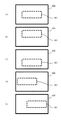
図6は、ステップS106の処理における表示範囲のシフト例を概念的に示した図である。後方カメラ51は、車両の後方を広範囲に撮影するカメラである。図6において、表示範囲501は、後方カメラ51が撮影する後方カメラ51の撮影範囲500を、表示制御部104が切り取って表示パネル30の表示データとしている範囲である。
FIG. 6 is a diagram conceptually illustrating a display range shift example in the process of step S106. The
図6(a)は、後方カメラ51の撮影範囲500に対して、通常の状態における後方カメラ51の表示範囲501を示している。図6(b)は、ステップS106の処理がステップS101で検出された上方向のモーション検出に対して実行されたときの例であり、表示範囲501について、図6(a)より上方が表示される。図6(c)は、ステップS106の処理がステップS101で検出された下方向のモーション検出に対して実行されたときの例であり、表示範囲501について、図6(a)より下方が表示される。図6(d)は、ステップS106の処理がステップS101で検出された左方向のモーション検出に対して実行されたときの例であり、表示範囲501について、図6(a)より左方が表示される。図6(e)は、ステップS106の処理がステップS101で検出された右方向のモーション検出に対して実行されたときの例であり、表示範囲501について、図6(a)より右方が表示される。
FIG. 6A shows a
ステップS106の処理は、1回のモーション検出により、予め設定された最大シフト量をシフトさせてもよく、1回のモーション検出により、予め設定された最大シフト量の1/nのシフト量をシフトさせ、最大n回の同一方向のモーションの検出により最大シフト量までシフトさせてもよい。 The process of step S106 may shift a preset maximum shift amount by one motion detection, or a 1 / n shift amount of a preset maximum shift amount by one motion detection. The maximum shift amount may be detected by detecting motions in the same direction at most n times.
このような処理により、モーションセンサ40を用いた4方向のみのモーション検出で、機能の切り替えおよび表示範囲の操作を、安全性を損なわずに直感的に行うことができる。
With such a process, it is possible to intuitively perform function switching and display range operation with motion detection in only four directions using the
次に、本発明の第2の実施形態について説明する。第2の実施形態において第1の実施形態と、その構成および処理が共通する内容については、説明を省略する。 Next, a second embodiment of the present invention will be described. In the second embodiment, the description of the contents common to the first embodiment and the configuration and processing is omitted.
第2の実施形態に係る表示機能付きミラー装置12の構成は、後方カメラ51に加えて、図7に示すように、左側方カメラ52および右側方カメラ53が撮影した映像データを取得する。つまり、撮影制御部103は、後方カメラ51が撮影した映像に加えて、左側方カメラ52および右側方カメラ53の各々が撮影した映像を取得する。
The configuration of the
表示制御部105は、撮影制御部103が取得した後方カメラ51の映像データに加えて、左側方カメラ52および右側方カメラ53の映像データを、表示パネル35に表示させる処理を行う。具体的には、表示パネル35の形状に合わせた各々の映像データの切り取りや、映像の輝度や色調の調整、各々の映像データの合成などである。
The
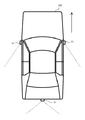
図8は、第2の実施形態に係る表示機能付きミラー装置12が映像データを取得するカメラの取付位置と撮影範囲の例を示す概念図であり、車両200を上方から見た態様を示している。図8において、矢印は車両200の前方を示し、破線は、後方カメラ51、左側方カメラ52および右側方カメラ53各々の撮影範囲を示している。後方カメラ51は、第1の実施形態においても同様であるが、車両200の後方に設置され、車両200の後方を広範囲に撮影する。左側方カメラ52および右側方カメラ53は、車両200の左右側方に各々設置され、車両200の左右後方を撮影する。左側方カメラ52および右側方カメラ53の設置位置は、図8の例においては、ドアミラーの位置であるが、フェンダー左右側方など、他の位置に設置されてもよい。
FIG. 8 is a conceptual diagram illustrating an example of a camera mounting position and a shooting range from which the
図9は、第2の実施形態に係る表示機能付きミラー装置12に用いられる表示機能付きルームミラー2をユーザである運転者側から見た外観図である。表示機能付きルームミラー2は、表示モード時に後方カメラ51の映像に加えて、左側方カメラ52および右側方カメラ53の映像を表示する点が表示機能付きルームミラー1と異なる。
FIG. 9 is an external view of the
図9に示す表示機能付きルームミラー2のミラー面21に示した破線は、各々のカメラの映像を表示する区画を示しており、左側方カメラ52の映像を表示する左表示区画60L、後方カメラ51の映像を表示する中央表示区画60C、右側方カメラ53の映像を表示する右表示区画60Rを示している。
The broken lines shown on the
図10は、図9に示す表示機能付きルームミラー2のb-b’の断面図を模式的に示した図である。
FIG. 10 is a diagram schematically showing a cross-sectional view taken along b-b ′ of the
図10に示すように、液晶パネル31の後方には、左表示区画60L、中央表示区画60Cおよび右表示区画60Rの位置に対応して独立に点灯制御可能な左バックライト32L、中央バックライト32Cおよび右バックライト32Rを備える。これらのバックライトは、各々独立していてもよく、1のバックライトが区画毎に点灯制御可能な形態であってもよい。表示パネル35は、液晶パネル31および左バックライト32L、中央バックライト32Cおよび右バックライト32Rにより構成される。また液晶パネル31および左バックライト32L、中央バックライト32Cおよび右バックライト32Rの組合せに代えて、区画毎に表示のON/OFFが制御される有機EL(Electro Luminescence)パネルなどの自発光表示パネルであってもよい。
As shown in FIG. 10, behind the
次に、図11を用いて、第2の実施形態に係る表示機能付きミラー装置12の表示切替方法について説明する。
Next, a display switching method of the
第2の実施形態において、表示モードとは、左表示区画60L、中央表示区画60Cおよび右表示区画60Rに、後方カメラ51、左側方カメラ52および右側方カメラ53の映像が表示されている状態である。また、ミラーモードには2のパターンがある。第1のミラーモードでは、全ての表示を行わない。第2のミラーモードでは、左表示区画60Lおよび右表示区画60Rに表示を行ない、中央表示区画60Cに表示を行わない。第2のミラーモードとして動作しているときは、表示制御部105は、液晶パネル31の中央表示区画60Cに該当する部分の表示を行わないとともに、中央バックライト32Cを消灯させる。
In the second embodiment, the display mode is a state in which images of the
ステップS102において、表示モードではなくミラーモードで動作していると判断された場合(ステップS102:No)、切替制御部108は、表示制御部105を制御して、表示パネル35の全ての区画に対する映像を表示させ、表示モードに変更する(ステップS203)。
In step S102, when it is determined that the operation is in the mirror mode instead of the display mode (step S102: No), the switching
ステップS104において、往復のモーションであると判断された場合(ステップS104:Yes)、切替制御部108は、表示機能付きルームミラー2の動作をミラーモードに変更する(ステップS205)。ステップS205において変更されるミラーモードは、第1のミラーモードであってもよいし、第2のミラーモードであってもよい。
If it is determined in step S104 that the motion is a reciprocating motion (step S104: Yes), the switching
ステップS104において、往復のモーションではないと判断された場合(ステップS104:No)、切替制御部108は表示制御部105を制御して、検出されたモーションの方向に、表示範囲をシフトさせる(ステップS206)。
If it is determined in step S104 that the motion is not a reciprocating motion (step S104: No), the switching
ステップS206の実行時、表示制御部105は、以下2種類のシフト処理を取りうることができる。第1のシフト処理としては、中央表示区画60Cに表示されている後方カメラ51の映像のみをシフトさせ、左表示区画60Lおよび右表示区画60Rに表示されている左側方カメラ52および右側方カメラ53の映像はシフトしない処理である。第1のシフト処理の場合、左表示区画60Lおよび右表示区画60Rに表示される映像は、ドアミラーで見る後方映像に相当するためにシフトさせる必要性が無く、央表示区画60Cに表示されている映像は、ルームミラーで見る映像に相当するために、必要に応じてシフトさせる。このような処理により、ユーザはミラーモードと表示モードとの切り替えおよび表示モード時における必要な表示対象の表示範囲の操作を、安全性を損なわずに直感的に行うことができる。
When executing step S206, the
また、第2のシフト処理としては、中央表示区画60Cに表示されている後方カメラ51の映像に加えて、左表示区画60Lおよび右表示区画60Rに表示されている左側方カメラ52および右側方カメラ53の映像も同様にシフトさせる処理である。第2のシフト処理の場合、表示機能付きルームミラー2が機構的に向きを変更できない場合であっても、同様の表示シフトを行うことができる。このような処理により、ユーザはミラーモードと表示モードとの切り替えおよび表示モード時における表示対象の表示範囲の操作を、安全性を損なわずに直感的に行うことができる。
As the second shift process, in addition to the video of the
図12は、ステップS206の処理における表示範囲のシフト例を概念的に示した図である。図12は、第2のシフト処理の例を示している。図12において、後方カメラ51の撮影範囲500における表示範囲501は、後方カメラ51が撮影する後方カメラ51の撮影範囲500を、表示制御部105が切り取って表示パネル35の表示データとしている範囲である。同様に、図12において、左側方カメラ52の撮影範囲510における表示範囲511は、左側方カメラ52が撮影する左側方カメラ52の撮影範囲510を、表示制御部105が切り取って表示パネル35の表示データとしている範囲である。また、図12において、右側方カメラ53の撮影範囲520における表示範囲521は、右側方カメラ53が撮影する右側方カメラ53の撮影範囲520を、表示制御部105が切り取って表示パネル35の表示データとしている範囲である。
FIG. 12 is a diagram conceptually illustrating a display range shift example in the process of step S206. FIG. 12 shows an example of the second shift process. In FIG. 12, the
表示制御部105は、各々の方向へシフト処理を行った場合、後方カメラ51の撮影範囲500における表示範囲501、左側方カメラ52の撮影範囲510における表示範囲511および右側方カメラ53の撮影範囲520における表示範囲521を合成して液晶パネル31に表示させる。
When the
本発明の実施の形態は、その要旨を逸脱しない限り様々に変更可能である。例えば、第1の実施形態において、ステップS106のシフト処理において表示される後方カメラ51の撮影範囲500における表示範囲501は、シフト前の表示範囲に比して表示範囲を変化させてもよい。例えば、シフト後の後方カメラ51の撮影範囲500における表示範囲501をシフト前より表示範囲を狭くする場合、表示範囲のズームと同等の効果が得られる。このため、モーション検出により表示範囲の移動指示を行った範囲を詳細に目視することができる。また、シフト後の後方カメラ51の撮影範囲500における表示範囲501をシフト前より表示範囲を広くする場合、表示範囲を広角にすることができる。これらの処理は、予め設定されていてもよく、さらにはステップS101で検出したモーションを示すピーク波形の時間長でいずれかを決定してもよい。具体的には、ステップS101で検出したモーションを示すピーク波形が、閾値の例として0.4秒未満であればシフト後の後方カメラ51の撮影範囲500における表示範囲501をシフト前より狭くし、閾値以上且つモーションとして認識される上限の時間長であれば、シフト後の後方カメラ51の撮影範囲500における表示範囲501をシフト前より広くする等である。
The embodiment of the present invention can be variously modified without departing from the gist thereof. For example, in the first embodiment, the
同様のモーション検出を第2の実施形態に適用すると、ステップS101で検出したモーションを示すピーク波形の時間長が閾値未満の場合は、モーション検出方向に対応する左側方カメラ52の撮影範囲510における表示範囲511または右側方カメラ53の撮影範囲520における表示範囲521のいずれかを狭く切り取り、閾値以上であれば広く切り取る。
When the same motion detection is applied to the second embodiment, when the time length of the peak waveform indicating the motion detected in step S101 is less than the threshold value, the display in the
1、2 表示機能付きルームミラー
10、12 表示機能付きミラー装置
20 カバー
21 ミラー面
22 ハーフミラー
30、35 表示パネル
31 液晶パネル
32 バックライト
32L 左バックライト
32R 右バックライト
32C 中央バックライト
40 モーションセンサ
41U 上方向検出フォトダイオード
41D 下方向検出フォトダイオード
41L 左方向検出フォトダイオード
41R 右方向検出フォトダイオード
51 後方カメラ(撮像装置)
52 左側方カメラ(撮像装置)
53 右側方カメラ(撮像装置)
60L 左表示区画
60C 中央表示区画
60R 右表示区画
100 制御部
102、103 撮影制御部
104、105 表示制御部
106 モーション制御部
108 切替制御部
200 車両
500 後方カメラの撮影範囲
501 後方カメラの撮影範囲における表示範囲
510 左側方カメラの撮影範囲
511 左側方カメラの撮影範囲における表示範囲
520 右側方カメラの撮影範囲
521 右側方カメラの撮影範囲における表示範囲
1, 2 Room mirror with
52 Left-side camera (imaging device)
53 Right-side camera (imaging device)
60L Left display section 60C Central display section 60R
Claims (5)
モーション検出を行うモーションセンサと、
前記表示機能付きルームミラーが、前記表示パネルの表示が停止され前記ハーフミラーのミラー面を用いたルームミラーとして機能しているときは、前記モーションセンサが検出した方向のうちいずれの方向におけるモーション検出結果においても、前記表示パネルの表示を実行させる表示機能へ切り替える処理を行い、前記表示機能付きルームミラーが、前記表示パネルの表示が行われている表示機能を実行しているときは、前記モーションセンサが検出したモーション検出は、各々の方向に対する表示範囲の移動指示として処理する、切替制御部と、
前記モーションセンサが検出したモーション検出が、各々の方向に対する表示範囲の移動指示である場合、前記モーションセンサが検出したモーション検出に基づいて、表示範囲を移動させるとともに、表示される範囲の広さを変化させる、表示制御部と、
を備えることを特徴とする表示機能付きミラー装置。 A room mirror with a display function, comprising: a display panel that displays an image of an imaging device that captures the rear of the vehicle; and a half mirror provided on a display surface of the display panel;
A motion sensor for motion detection,
When the display function room mirror functions as a room mirror using the mirror surface of the half mirror when the display on the display panel is stopped, motion detection in any direction detected by the motion sensor Even in the result, the process of switching to the display function for executing the display of the display panel is performed, and when the room mirror with the display function is executing the display function for displaying the display panel, the motion is Motion detection detected by the sensor is processed as an instruction to move the display range with respect to each direction, a switching control unit,
When the motion detection detected by the motion sensor is an instruction to move the display range in each direction, the display range is moved based on the motion detection detected by the motion sensor, and the width of the displayed range is increased. Changing the display control unit;
A mirror device with a display function.
請求項1に記載の表示機能付きミラー装置。 When the motion detection detected by the motion sensor is an instruction to move the display range in each direction, the display control unit moves the display range and narrows the displayed range.
The mirror device with a display function according to claim 1.
請求項1に記載の表示機能付きミラー装置。 When the motion detection detected by the motion sensor is an instruction to move the display range in each direction, the display control unit moves the display range and widely changes the displayed range.
The mirror device with a display function according to claim 1.
請求項1に記載の表示機能付きミラー装置。 When the motion detection detected by the motion sensor is an instruction to move the display range in each direction, the display control unit moves the display range and the time length of the peak waveform of the motion detection waveform is less than a threshold value. Change the displayed range narrowly, and if it is above the threshold, change the displayed range widely.
The mirror device with a display function according to claim 1.
A display panel that displays an image of an imaging device that captures the rear of a vehicle, and a room mirror with a display function that includes a half mirror provided on a display surface of the display panel. When functioning as a room mirror using a surface, in the motion detection result in any direction detected by the motion sensor that performs motion detection, switching to a display function for executing display on the display panel, When the room mirror with a display function is executing a display function in which display of the display panel is performed, the motion detection detected by the motion sensor gives an instruction to move the display range with respect to each direction, The displayed range is based on the motion detection detected by the motion sensor. Changing the size of, display switching method.
Priority Applications (1)
| Application Number | Priority Date | Filing Date | Title |
|---|---|---|---|
| JP2016142164A JP6229769B2 (en) | 2016-07-20 | 2016-07-20 | Mirror device with display function and display switching method |
Applications Claiming Priority (1)
| Application Number | Priority Date | Filing Date | Title |
|---|---|---|---|
| JP2016142164A JP6229769B2 (en) | 2016-07-20 | 2016-07-20 | Mirror device with display function and display switching method |
Related Parent Applications (1)
| Application Number | Title | Priority Date | Filing Date |
|---|---|---|---|
| JP2014184110A Division JP5983693B2 (en) | 2014-09-10 | 2014-09-10 | Mirror device with display function and display switching method |
Related Child Applications (1)
| Application Number | Title | Priority Date | Filing Date |
|---|---|---|---|
| JP2017198434A Division JP2018002152A (en) | 2017-10-12 | 2017-10-12 | Mirror device with display function and display switching method |
Publications (2)
| Publication Number | Publication Date |
|---|---|
| JP2016199266A true JP2016199266A (en) | 2016-12-01 |
| JP6229769B2 JP6229769B2 (en) | 2017-11-15 |
Family
ID=57422411
Family Applications (1)
| Application Number | Title | Priority Date | Filing Date |
|---|---|---|---|
| JP2016142164A Active JP6229769B2 (en) | 2016-07-20 | 2016-07-20 | Mirror device with display function and display switching method |
Country Status (1)
| Country | Link |
|---|---|
| JP (1) | JP6229769B2 (en) |
Cited By (3)
| Publication number | Priority date | Publication date | Assignee | Title |
|---|---|---|---|---|
| JP2020500780A (en) * | 2016-12-16 | 2020-01-16 | ジェンテックス コーポレイション | Foldable external display mirror |
| KR102095676B1 (en) * | 2019-04-25 | 2020-03-31 | 유니텔전자 (주) | Device and Method for Displaying Video from Side Rear View of Vehicle |
| CN112005160A (en) * | 2018-04-20 | 2020-11-27 | 市光工业株式会社 | Vehicle reflecting mirror |
Citations (8)
| Publication number | Priority date | Publication date | Assignee | Title |
|---|---|---|---|---|
| JP3084469U (en) * | 2001-09-03 | 2002-03-22 | 株式会社コムテック | Operation image display system |
| JP2005534246A (en) * | 2002-07-25 | 2005-11-10 | コーニンクレッカ フィリップス エレクトロニクス エヌ ヴィ | View system |
| JP2006185610A (en) * | 2004-12-24 | 2006-07-13 | Denso Corp | Switching device utilizing vehicular room mirror |
| JP2007147331A (en) * | 2005-11-24 | 2007-06-14 | Univ Nihon | Straightness measuring method and device |
| JP2009100180A (en) * | 2007-10-16 | 2009-05-07 | Denso Corp | Vehicular rear monitoring device |
| JP2009529452A (en) * | 2006-03-09 | 2009-08-20 | ジェンテックス コーポレイション | Vehicle rear view assembly including high brightness display |
| JP2014093768A (en) * | 2012-10-31 | 2014-05-19 | Hyundai Motor Company Co Ltd | Apparatus and method for controlling image on room mirror |
| JP2014097781A (en) * | 2012-11-13 | 2014-05-29 | Avisonic Technology Corp | Vehicular image system and display control method for vehicular image |
-
2016
- 2016-07-20 JP JP2016142164A patent/JP6229769B2/en active Active
Patent Citations (8)
| Publication number | Priority date | Publication date | Assignee | Title |
|---|---|---|---|---|
| JP3084469U (en) * | 2001-09-03 | 2002-03-22 | 株式会社コムテック | Operation image display system |
| JP2005534246A (en) * | 2002-07-25 | 2005-11-10 | コーニンクレッカ フィリップス エレクトロニクス エヌ ヴィ | View system |
| JP2006185610A (en) * | 2004-12-24 | 2006-07-13 | Denso Corp | Switching device utilizing vehicular room mirror |
| JP2007147331A (en) * | 2005-11-24 | 2007-06-14 | Univ Nihon | Straightness measuring method and device |
| JP2009529452A (en) * | 2006-03-09 | 2009-08-20 | ジェンテックス コーポレイション | Vehicle rear view assembly including high brightness display |
| JP2009100180A (en) * | 2007-10-16 | 2009-05-07 | Denso Corp | Vehicular rear monitoring device |
| JP2014093768A (en) * | 2012-10-31 | 2014-05-19 | Hyundai Motor Company Co Ltd | Apparatus and method for controlling image on room mirror |
| JP2014097781A (en) * | 2012-11-13 | 2014-05-29 | Avisonic Technology Corp | Vehicular image system and display control method for vehicular image |
Cited By (6)
| Publication number | Priority date | Publication date | Assignee | Title |
|---|---|---|---|---|
| JP2020500780A (en) * | 2016-12-16 | 2020-01-16 | ジェンテックス コーポレイション | Foldable external display mirror |
| JP7005626B2 (en) | 2016-12-16 | 2022-01-21 | ジェンテックス コーポレイション | Foldable external display mirror |
| CN112005160A (en) * | 2018-04-20 | 2020-11-27 | 市光工业株式会社 | Vehicle reflecting mirror |
| KR102095676B1 (en) * | 2019-04-25 | 2020-03-31 | 유니텔전자 (주) | Device and Method for Displaying Video from Side Rear View of Vehicle |
| WO2020218712A1 (en) * | 2019-04-25 | 2020-10-29 | 유니텔전자(주) | Device for displaying lateral rear images of vehicle and method therefor |
| US11661008B2 (en) | 2019-04-25 | 2023-05-30 | Unitel Electronics Co., Ltd. | Device for displaying lateral rear images of vehicle and method therefor |
Also Published As
| Publication number | Publication date |
|---|---|
| JP6229769B2 (en) | 2017-11-15 |
Similar Documents
| Publication | Publication Date | Title |
|---|---|---|
| JP5983693B2 (en) | Mirror device with display function and display switching method | |
| JP2016055782A5 (en) | ||
| US11052823B2 (en) | Vehicle rear monitoring system | |
| US9123179B2 (en) | Surrounding image display system and surrounding image display method for vehicle | |
| JP5277974B2 (en) | Driving assistance device | |
| US10186234B2 (en) | Mirror device with display function and method of changing direction of mirror device with display function | |
| EP3562708B1 (en) | Rear vision system with eye-tracking | |
| JP6481971B2 (en) | Crew photographing device | |
| JP6585662B2 (en) | Vehicle roof mounting system | |
| JP2010130647A (en) | Vehicle periphery checking system | |
| CN105960355A (en) | Method for operating a rearview camera system of a motor vehicle after detection of a headlight flasher, rearview camera system and motor vehicle | |
| CN110901531B (en) | Rear display device, rear display method, and recording medium | |
| JP6229769B2 (en) | Mirror device with display function and display switching method | |
| JP2017202741A (en) | Vehicular visual observation apparatus | |
| JP6481970B2 (en) | Driver shooting device | |
| US20160368418A1 (en) | Rear-view monitor device and automobile equipeed with same | |
| US10261580B2 (en) | Mirror device with display function and method of changing direction of mirror device with display function | |
| JP2009035162A (en) | Rear view monitoring device | |
| JP2018002152A (en) | Mirror device with display function and display switching method | |
| JP2010208372A (en) | Brightness adjusting device | |
| JP6593713B2 (en) | Crew photographing device | |
| JP2020093574A (en) | Display control device, display control system, display control method, and display control program | |
| JP2019001293A (en) | On-vehicle display device | |
| JP2018074440A (en) | Vehicle rear image display device | |
| JP6649791B2 (en) | Vehicle ornaments |
Legal Events
| Date | Code | Title | Description |
|---|---|---|---|
| A977 | Report on retrieval |
Free format text: JAPANESE INTERMEDIATE CODE: A971007 Effective date: 20170705 |
|
| A131 | Notification of reasons for refusal |
Free format text: JAPANESE INTERMEDIATE CODE: A131 Effective date: 20170808 |
|
| A521 | Request for written amendment filed |
Free format text: JAPANESE INTERMEDIATE CODE: A523 Effective date: 20170825 |
|
| TRDD | Decision of grant or rejection written | ||
| A01 | Written decision to grant a patent or to grant a registration (utility model) |
Free format text: JAPANESE INTERMEDIATE CODE: A01 Effective date: 20170919 |
|
| A61 | First payment of annual fees (during grant procedure) |
Free format text: JAPANESE INTERMEDIATE CODE: A61 Effective date: 20171002 |
|
| R150 | Certificate of patent or registration of utility model |
Ref document number: 6229769 Country of ref document: JP Free format text: JAPANESE INTERMEDIATE CODE: R150 |