EP3562708B1 - Rear vision system with eye-tracking - Google Patents
Rear vision system with eye-tracking Download PDFInfo
- Publication number
- EP3562708B1 EP3562708B1 EP17888325.2A EP17888325A EP3562708B1 EP 3562708 B1 EP3562708 B1 EP 3562708B1 EP 17888325 A EP17888325 A EP 17888325A EP 3562708 B1 EP3562708 B1 EP 3562708B1
- Authority
- EP
- European Patent Office
- Prior art keywords
- image
- vehicle
- vision system
- area
- rear vision
- Prior art date
- Legal status (The legal status is an assumption and is not a legal conclusion. Google has not performed a legal analysis and makes no representation as to the accuracy of the status listed.)
- Active
Links
- 230000004438 eyesight Effects 0.000 title claims description 19
- 238000004891 communication Methods 0.000 claims description 34
- 239000000758 substrate Substances 0.000 claims description 23
- 238000004091 panning Methods 0.000 claims description 2
- 210000003128 head Anatomy 0.000 description 25
- 238000000034 method Methods 0.000 description 12
- 230000008569 process Effects 0.000 description 9
- 230000000875 corresponding effect Effects 0.000 description 7
- 230000007935 neutral effect Effects 0.000 description 5
- 238000005286 illumination Methods 0.000 description 4
- 230000003287 optical effect Effects 0.000 description 4
- 238000002834 transmittance Methods 0.000 description 4
- 230000004913 activation Effects 0.000 description 3
- 230000008859 change Effects 0.000 description 3
- 238000001514 detection method Methods 0.000 description 3
- 230000006870 function Effects 0.000 description 3
- 239000003550 marker Substances 0.000 description 3
- 230000001276 controlling effect Effects 0.000 description 2
- 238000010586 diagram Methods 0.000 description 2
- 238000005516 engineering process Methods 0.000 description 2
- 210000000554 iris Anatomy 0.000 description 2
- 238000012986 modification Methods 0.000 description 2
- 230000004048 modification Effects 0.000 description 2
- 230000004308 accommodation Effects 0.000 description 1
- 230000000712 assembly Effects 0.000 description 1
- 238000000429 assembly Methods 0.000 description 1
- 230000000295 complement effect Effects 0.000 description 1
- 230000002596 correlated effect Effects 0.000 description 1
- 239000004973 liquid crystal related substance Substances 0.000 description 1
- 238000004519 manufacturing process Methods 0.000 description 1
- 238000013507 mapping Methods 0.000 description 1
- 239000011159 matrix material Substances 0.000 description 1
- 230000003278 mimic effect Effects 0.000 description 1
- 238000012544 monitoring process Methods 0.000 description 1
- 230000004044 response Effects 0.000 description 1
- 230000004043 responsiveness Effects 0.000 description 1
- 239000004065 semiconductor Substances 0.000 description 1
- 238000001228 spectrum Methods 0.000 description 1
- 230000003068 static effect Effects 0.000 description 1
Images


Classifications
-
- B—PERFORMING OPERATIONS; TRANSPORTING
- B60—VEHICLES IN GENERAL
- B60R—VEHICLES, VEHICLE FITTINGS, OR VEHICLE PARTS, NOT OTHERWISE PROVIDED FOR
- B60R1/00—Optical viewing arrangements; Real-time viewing arrangements for drivers or passengers using optical image capturing systems, e.g. cameras or video systems specially adapted for use in or on vehicles
- B60R1/20—Real-time viewing arrangements for drivers or passengers using optical image capturing systems, e.g. cameras or video systems specially adapted for use in or on vehicles
- B60R1/22—Real-time viewing arrangements for drivers or passengers using optical image capturing systems, e.g. cameras or video systems specially adapted for use in or on vehicles for viewing an area outside the vehicle, e.g. the exterior of the vehicle
- B60R1/23—Real-time viewing arrangements for drivers or passengers using optical image capturing systems, e.g. cameras or video systems specially adapted for use in or on vehicles for viewing an area outside the vehicle, e.g. the exterior of the vehicle with a predetermined field of view
- B60R1/26—Real-time viewing arrangements for drivers or passengers using optical image capturing systems, e.g. cameras or video systems specially adapted for use in or on vehicles for viewing an area outside the vehicle, e.g. the exterior of the vehicle with a predetermined field of view to the rear of the vehicle
-
- B—PERFORMING OPERATIONS; TRANSPORTING
- B60—VEHICLES IN GENERAL
- B60R—VEHICLES, VEHICLE FITTINGS, OR VEHICLE PARTS, NOT OTHERWISE PROVIDED FOR
- B60R1/00—Optical viewing arrangements; Real-time viewing arrangements for drivers or passengers using optical image capturing systems, e.g. cameras or video systems specially adapted for use in or on vehicles
- B60R1/12—Mirror assemblies combined with other articles, e.g. clocks
-
- B—PERFORMING OPERATIONS; TRANSPORTING
- B60—VEHICLES IN GENERAL
- B60R—VEHICLES, VEHICLE FITTINGS, OR VEHICLE PARTS, NOT OTHERWISE PROVIDED FOR
- B60R1/00—Optical viewing arrangements; Real-time viewing arrangements for drivers or passengers using optical image capturing systems, e.g. cameras or video systems specially adapted for use in or on vehicles
- B60R1/02—Rear-view mirror arrangements
- B60R1/04—Rear-view mirror arrangements mounted inside vehicle
-
- B—PERFORMING OPERATIONS; TRANSPORTING
- B60—VEHICLES IN GENERAL
- B60R—VEHICLES, VEHICLE FITTINGS, OR VEHICLE PARTS, NOT OTHERWISE PROVIDED FOR
- B60R1/00—Optical viewing arrangements; Real-time viewing arrangements for drivers or passengers using optical image capturing systems, e.g. cameras or video systems specially adapted for use in or on vehicles
- B60R1/20—Real-time viewing arrangements for drivers or passengers using optical image capturing systems, e.g. cameras or video systems specially adapted for use in or on vehicles
- B60R1/22—Real-time viewing arrangements for drivers or passengers using optical image capturing systems, e.g. cameras or video systems specially adapted for use in or on vehicles for viewing an area outside the vehicle, e.g. the exterior of the vehicle
- B60R1/28—Real-time viewing arrangements for drivers or passengers using optical image capturing systems, e.g. cameras or video systems specially adapted for use in or on vehicles for viewing an area outside the vehicle, e.g. the exterior of the vehicle with an adjustable field of view
-
- B—PERFORMING OPERATIONS; TRANSPORTING
- B60—VEHICLES IN GENERAL
- B60R—VEHICLES, VEHICLE FITTINGS, OR VEHICLE PARTS, NOT OTHERWISE PROVIDED FOR
- B60R11/00—Arrangements for holding or mounting articles, not otherwise provided for
- B60R11/02—Arrangements for holding or mounting articles, not otherwise provided for for radio sets, television sets, telephones, or the like; Arrangement of controls thereof
- B60R11/0229—Arrangements for holding or mounting articles, not otherwise provided for for radio sets, television sets, telephones, or the like; Arrangement of controls thereof for displays, e.g. cathodic tubes
- B60R11/0235—Arrangements for holding or mounting articles, not otherwise provided for for radio sets, television sets, telephones, or the like; Arrangement of controls thereof for displays, e.g. cathodic tubes of flat type, e.g. LCD
-
- G—PHYSICS
- G06—COMPUTING; CALCULATING OR COUNTING
- G06V—IMAGE OR VIDEO RECOGNITION OR UNDERSTANDING
- G06V20/00—Scenes; Scene-specific elements
- G06V20/50—Context or environment of the image
- G06V20/59—Context or environment of the image inside of a vehicle, e.g. relating to seat occupancy, driver state or inner lighting conditions
-
- B—PERFORMING OPERATIONS; TRANSPORTING
- B60—VEHICLES IN GENERAL
- B60R—VEHICLES, VEHICLE FITTINGS, OR VEHICLE PARTS, NOT OTHERWISE PROVIDED FOR
- B60R1/00—Optical viewing arrangements; Real-time viewing arrangements for drivers or passengers using optical image capturing systems, e.g. cameras or video systems specially adapted for use in or on vehicles
- B60R1/12—Mirror assemblies combined with other articles, e.g. clocks
- B60R2001/1223—Mirror assemblies combined with other articles, e.g. clocks with sensors or transducers
-
- B—PERFORMING OPERATIONS; TRANSPORTING
- B60—VEHICLES IN GENERAL
- B60R—VEHICLES, VEHICLE FITTINGS, OR VEHICLE PARTS, NOT OTHERWISE PROVIDED FOR
- B60R1/00—Optical viewing arrangements; Real-time viewing arrangements for drivers or passengers using optical image capturing systems, e.g. cameras or video systems specially adapted for use in or on vehicles
- B60R1/12—Mirror assemblies combined with other articles, e.g. clocks
- B60R2001/1253—Mirror assemblies combined with other articles, e.g. clocks with cameras, video cameras or video screens
-
- B—PERFORMING OPERATIONS; TRANSPORTING
- B60—VEHICLES IN GENERAL
- B60R—VEHICLES, VEHICLE FITTINGS, OR VEHICLE PARTS, NOT OTHERWISE PROVIDED FOR
- B60R2300/00—Details of viewing arrangements using cameras and displays, specially adapted for use in a vehicle
- B60R2300/10—Details of viewing arrangements using cameras and displays, specially adapted for use in a vehicle characterised by the type of camera system used
- B60R2300/101—Details of viewing arrangements using cameras and displays, specially adapted for use in a vehicle characterised by the type of camera system used using cameras with adjustable capturing direction
-
- B—PERFORMING OPERATIONS; TRANSPORTING
- B60—VEHICLES IN GENERAL
- B60R—VEHICLES, VEHICLE FITTINGS, OR VEHICLE PARTS, NOT OTHERWISE PROVIDED FOR
- B60R2300/00—Details of viewing arrangements using cameras and displays, specially adapted for use in a vehicle
- B60R2300/10—Details of viewing arrangements using cameras and displays, specially adapted for use in a vehicle characterised by the type of camera system used
- B60R2300/103—Details of viewing arrangements using cameras and displays, specially adapted for use in a vehicle characterised by the type of camera system used using camera systems provided with artificial illumination device, e.g. IR light source
-
- B—PERFORMING OPERATIONS; TRANSPORTING
- B60—VEHICLES IN GENERAL
- B60R—VEHICLES, VEHICLE FITTINGS, OR VEHICLE PARTS, NOT OTHERWISE PROVIDED FOR
- B60R2300/00—Details of viewing arrangements using cameras and displays, specially adapted for use in a vehicle
- B60R2300/60—Details of viewing arrangements using cameras and displays, specially adapted for use in a vehicle characterised by monitoring and displaying vehicle exterior scenes from a transformed perspective
- B60R2300/602—Details of viewing arrangements using cameras and displays, specially adapted for use in a vehicle characterised by monitoring and displaying vehicle exterior scenes from a transformed perspective with an adjustable viewpoint
-
- B—PERFORMING OPERATIONS; TRANSPORTING
- B60—VEHICLES IN GENERAL
- B60R—VEHICLES, VEHICLE FITTINGS, OR VEHICLE PARTS, NOT OTHERWISE PROVIDED FOR
- B60R2300/00—Details of viewing arrangements using cameras and displays, specially adapted for use in a vehicle
- B60R2300/70—Details of viewing arrangements using cameras and displays, specially adapted for use in a vehicle characterised by an event-triggered choice to display a specific image among a selection of captured images
-
- B—PERFORMING OPERATIONS; TRANSPORTING
- B60—VEHICLES IN GENERAL
- B60R—VEHICLES, VEHICLE FITTINGS, OR VEHICLE PARTS, NOT OTHERWISE PROVIDED FOR
- B60R2300/00—Details of viewing arrangements using cameras and displays, specially adapted for use in a vehicle
- B60R2300/80—Details of viewing arrangements using cameras and displays, specially adapted for use in a vehicle characterised by the intended use of the viewing arrangement
- B60R2300/8066—Details of viewing arrangements using cameras and displays, specially adapted for use in a vehicle characterised by the intended use of the viewing arrangement for monitoring rearward traffic
Definitions
- the present disclosure relates generally to a full display mirror system and more particularly, relates to a control scheme for selecting an image portion to display based on a detected location of the eyes of the driver.
- DE 10 2012 223479 A1 describes an apparatus and method for controlling an image on a multifunction mirror, the apparatus for controlling an image on a multifunction mirror comprising: an angle sensor that measures the angle of a multifunction mirror in a vehicle; an operation detection unit that detects an operation angle of the multifunction mirror from the value measured by the angle sensor; a view change unit that generates a view-changed image by changing the view of an external image taken by a first camera attached to the vehicle based on the detected operating angle of the inside mirror; and an output control unit that controls the external image to be displayed on the multi-function mirror and controls a view-changed image according to the set angle of the multi-function mirror to be displayed on the multi-function mirror.
- a rear vision system for a vehicle includes a camera mounted with the vehicle and capturing a field of view of a first area rearward of the vehicle, a rearview mirror including a display substrate thereon, and an image sensor directed toward an interior of the vehicle and configured to capture image data of an object.
- the system further includes a controller in communication with the camera and receiving a first video image of the first area corresponding with the field of view and in communication with the image sensor to determine a position of the object within the image data.
- the controller is further in communication with the display substrate to present a sub-area of the first area on the display substrate. The sub-area is selected to simulate a reflected image from the field of view to the object by the substrate based on the determined position of the object.
- a rear vision system for a vehicle includes a camera mounted with the vehicle and capturing a field of view of a first area rearward of the vehicle, a display substrate mounted within an interior of the vehicle, and an image sensor directed toward the interior of the vehicle and positioned to capture image data of an object.
- the system further includes a processor in communication with the camera and receiving a first video image of the field of view and in communication with the image sensor to locate the object within the image data and to determine a position of the object relative to a predetermined two-dimensional coordinate system along a theoretical viewing distance from the substrate.
- the controller is further in communication with the display substrate to present a sub-area of the first area on the display substrate.
- the sub-area is selected to correlate the position of the position of the object with a two-dimensional coordinate system assigned to the first area based on a scale between the theoretical viewing distance and a predetermined estimated image distance from the rearview mirror to a theoretical image plane to the rear of the vehicle.
- a vehicle includes a camera mounted with the vehicle and capturing a field of view of a first area rearward of the vehicle and a rearview mirror positioned within an interior of the vehicle.
- the rearview mirror includes a display substrate mounted within an interior of the vehicle and an image sensor directed toward the interior of the vehicle and positioned to capture image data of an object.
- the vehicle further includes a controller in communication with the camera and receiving a first video image of the field of view and in communication with the image sensor to locate the object within the image data and to determine a position of the object relative to a predetermined two-dimensional coordinate system along a theoretical viewing distance from the substrate.
- the controller is further in communication with the display substrate to present a sub-area of the first area on the display substrate.
- the sub-area is selected to correlate the position of the position of the object with a two-dimensional coordinate system assigned to the first area based on a scale between the theoretical viewing distance and a predetermined estimated image distance from the rearview mirror to a theoretical image plane to the rear of the vehicle.
- the terms "upper,” “lower,” “right,” “left,” “rear,” “front,” “vertical,” “horizontal,” and derivatives thereof shall relate to the device as oriented in FIG. 1 .
- the device may assume various alternative orientations and step sequences, except where expressly specified to the contrary.
- the specific devices and processes illustrated in the attached drawings, and described in the following specification are simply exemplary embodiments of the inventive concepts defined in the appended claims. Hence, specific dimensions and other physical characteristics relating to the embodiments disclosed herein are not to be considered as limiting, unless the claims expressly state otherwise.
- reference numeral 10 indicates a rear vision system for a vehicle 12 ( FIG. 2 ).
- System 10 includes a camera 14 capturing a field of view 16 ( FIG. 4 ) rearward (e.g. in rear direction 18) of the vehicle 12 and a rearview mirror 20 including a display substrate 22 thereon.
- System 10 further includes an image sensor 24 ( FIG. 6 ) directed toward an interior 26 of vehicle 12 and configured to capture image data of an object that, in an example, may include the eyes 34 or head 36 (both the eyes 34 and head 36 being generally indicated with respect to various identified positions thereof, designated as eyes 34a, 34b, etc. and head 36a, 36b, etc.) of a driver of vehicle 12.
- a control unit 28 is in communication with the camera 14 to receive a first image 30 (also being generally indicated with respect to various identified areas thereof, designated as image 30a, 30b, etc.) of the field of view 16.
- Control unit 28 is further coupled with the image sensor 24 to determine a position of the object (e.g., the eyes 34 or head 36 of the driver) within the image data and is also in communication with the display substrate 22 to present a portion 32 (also being generally indicated with respect to various identified portions, designated as portion 32a, 32b, etc.) of the video image 30 thereon of a sub-area that is smaller than the area of the field of view 16.
- the sub-area is selected to simulate a reflected image from the field of view 16 to the object by the display substrate 22 based on the determined position of the object.
- control unit 28 can be any suitable component or structure, including multiple, connected components or structures, within or associated with vehicle 12 that can receive the image 30 from camera 14 for presentation on display 22, detect the position of an object (e.g., the head 36 or eyes 34 of a driver), and present the portion 32 of the image 30 corresponding to the object position on display 22, according to the scheme disclosed herein.
- control unit 28 may be or include specific functionality within a computer system on-board vehicle 12.
- control unit 28 may comprise dedicated computer chips (e.g., application-specific integrated circuits) respectively connected with the sensor 24 and camera 14, and further in communication at least with each other.
- FIG. 2 a schematic depiction is shown in which the head 36 of a driver of vehicle 12 is shown in various positions 36a and 36b with respect to a "standard" rearview mirror 40.
- a standard rearview mirror 40 can be considered as a reflective rearview mirror that the driver uses to view a reflected image out of a rear windshield 42 of vehicle 12 and to the rear of vehicle 12 in direction 18.
- the driver has a limited view toward the rear of vehicle 12 that corresponds to a mirror field 44 determined by incidence lines taken from the respective eyes 34 of the driver to the corresponding edges of the reflective surface of standard mirror 40 and corresponding reflection lines that, according to general optics principles, are at an equal angle to the incidence lines about a plane normal to the reflective surface.
- the particular mirror field 44 and the accompanying portion of the area to the rear of vehicle 12 viewable through standard mirror 40 can be adjusted by changing the particular angle of the standard mirror 40 itself or by the driver moving his or her head 36 and, thereby, changing the angles of the incidence lines from the eyes 34 to the standard mirror 40.
- the driver may position the standard mirror 40 to correspond with the view that the driver would like to have available using standard mirror 40 when the driver's head 36 is in a comfortable, neutral seating position.
- the driver may wish to view an object or the like outside of this neutral mirror field 44 and may, accordingly, move his or her head 36, such as from a position 36a in FIG. 1 to a position 36b to instinctively provide a different view by an adjusted mirror field 44, such as from mirror field 44a to mirror field 44b, which is shown having moved both horizontally and vertically.
- an adjusted mirror field 44 such as from mirror field 44a to mirror field 44b, which is shown having moved both horizontally and vertically.
- control unit 28 may, as discussed above, be configured to replicate the adjustment of the image presented on display 22 to correspond with the adjustment that the driver expects when moving his or her head 36 with respect to the illustrated standard mirror 40, while maintaining the image at a predetermined scale that matches what would be seen in a theoretical reflection based on general estimates of the driver position and of the view to the rear of vehicle 12.
- vehicle 12 including system 10 can include camera 14 positioned on the rear of vehicle 12. In the illustrated example, camera 14 is positioned on the liftgate of the vehicle 12 beneath the rear windshield 42 included therein.
- the camera 14 can be positioned within the interior of vehicle 12, such as along the headliner of the vehicle 12 with camera 14 adjacent to and directed out of rear windshield 42. Still further arrangements are possible and can be schematically similar to the depiction in FIG. 3 . As illustrated, camera 14 can be configured such that the field of view 16 thereof is greater than that of the general size of mirror field 44 that would correspond to display 22 if it were a standard reflective surface. As illustrated, field of view 16 can be, for example, 90 degrees or greater, including angles of at least 120 degrees or the like. Accordingly, control unit 28 may crop the image 30 taken by camera 14, as illustrated in FIG. 1 , such that the portion 32 of image 30 shown on display 22 generally mimics how a reflected image would appear. This includes both the size of the images projected and the viewing angle of the portion 32 of image 30.
- a theoretical image plane 46 is shown to represent the overall image 30 taken by camera 14 with the depicted field of view 16.
- the driver of vehicle 12 when viewing the image portion 32 on display 22 may expect the image portion 32 to change when the driver's head 36 is moved, based on prior experience with standard mirrors 40.
- system 10 can accommodate the driver's expectations by tracking the position of the driver's head 36 or, specifically, the eyes 34 of the driver with respect to mirror 20 and may pan the image 30 with respect to the portion 32 shown on display 22. This accommodation is schematically depicted in FIG.
- the portions 32a and 32b of the image plane 46 correspond to example head positions 36a,36b, determined by the location of the eyes 34a and 34b, with respect to display 22, such as by mapping the determined locations of eyes 34a and 34b to a two-dimensional coordinate system that correlates with a similar coordinate system that can be applied to image 30, or a general inference of the eye position made by detecting the position 36a,36b of the head 36, based on the same optical principles of the standard mirror 40 depicted in FIG. 2 , which may be done using predetermined scale factors for image movement based on the distance between positions of eyes 34a and 34b.
- the movement of image 30 with respect to the portion 32 thereof shown on display 22 can be independent of the positioning of mirror 20.
- the portion 32 can be based on a baseline image that can be predetermined and stored in memory 70 ( FIG. 8 ) at the time of manufacture, for example.
- the position 34a,34b of the eyes 34 or 36a,36b of the head 36 at, for example, the time of activation of system 10 can be established and correlated with a baseline portion 32a of image 30 that corresponds to, for example, a directly rearward 18 view within the field of view 16.
- an input 54 can be provided to allow the driver to adjust the baseline image according to needs or desires.
- such a baseline image can correspond with a particular estimated field of view 16 of an average driver at a neutral (i.e. aligning with the longitudinal axis of vehicle 12) position of mirror 20.
- system 10 can track the movement of mirror 20, itself, communicating such movement (or the absolute position thereof) to control unit 28 that can adjust the displayed portion 32 of image 30 based on such movement, in a way determined to mimic the movement of a reflective mirror.
- Such tracking can be done by positioning a marker within the interior 26 of vehicle 12 that can be located using sensor 24 (when included in mirror 20) or using a magnetic or mechanical sensor embedded in the mounting structure of mirror 20 that facilitates movement thereof.
- the control unit 28 may be able to use head 36 or eye 34 tracking in combination with the tracking of the marker relative to the image sensor 24 to determine the desired image portion 32 directly.
- System 10 can continue to track the location of the head 36 or eyes 34 and can pan the image 30 with respect to the displayed portion 32 according to movement thereof to correspond with an expected movement based on optical principles, as discussed above. As shown, such movement can be both horizontal and vertical and can be generally opposite the movement of the eyes 34. The movement can be calibrated in advance and/or can be adjustable by the driver. In certain modes of use, the vertical tracking shown in FIG. 5 may present advantages over static displays due, at least in part, to the short aspect-ratio of the portion 32 of image 30 presented on display 22 (due to the display 22 typically being wider than it is tall). For example, the tracking functionality disclosed herein may allow the driver to move or tilt his or her head 36 upward, such as by raising his or her seat within vehicle 12.
- the portion 32 of image 30 would pan downwardly to allow the driver, for example, to view an area immediately behind the vehicle 12 (such as adjacent the rear bumper). It is noted, that such a position may not be visible using a standard reflective rearview mirror 40, as the view would be blocked by the trunk area or rear deck, depending on the vehicle type.
- a second camera can be included, for example, within the rear bumper or adjacent the license plate of vehicle 12. Such a camera may be particularly useful when camera 14 is adjacent the headliner of vehicle 12 to remove distortion.
- control unit 28 can employ an image stitching function, algorithm, or the like to provide smooth transitioning between the respective camera images to still effectively present a single image 30 for panning in the above-described manner.
- control unit 28 will pan the portion 32 of image 30 back toward the portion that corresponds with the neutral viewing position.
- the sensor 24 can be included in mirror 20.
- the position of the eyes 34 may vary depending on the orientation of mirror 20.
- the mirror 20 may have a reflective, partially transparent surface overlying display 22 so that mirror 20 can be used as a standard mirror 40 when, for example, display 22 is inactive.
- the user may adjust mirror 20 to provide the desired baseline view prior to activation of display 22, meaning that the predetermined baseline image, as well as the position of eyes 34 detected by sensor 24 may closely correspond with the preselected portion 32 of image 30 presented on display 22 or a previously-adjusted variation thereof.
- activation of display 22 can correspond with upward tilting of display 22 to reduce competition of the actual reflected image.
- Control unit 28 may compensate for such adjustment in the selection of the portion 32 of image 30 presented on display 22.
- sensor 24 may be located elsewhere in vehicle 12, such as in an overhead console adjacent mirror 20 or the like.
- the portion 32 of image 30 selected based on the detected position of eyes 34 may be independent of the mirror position.
- system 10 may also be configured to determine the position of mirror 20, particularly of display 22 thereof, to correlate the portion 32 of image 30 to the detected position of display 22. In an example, this tracking can be done using various mechanical or magnetic sensors, as discussed above. In this manner, as discussed above, the diver may be able to physically move mirror 20 to change the baseline portion 32 of image 30 presented on display 22, thereby removing a need for an input 54. Additional variations are also possible, wherein mirror 20 may include a sensor 24 therein and may also incorporate monitoring of the position of display 22 to provide similar adjustment and responsiveness.
- the tracking functionality may utilize an infrared illumination of the area viewable by sensor 24.
- the control unit 28 may be able to identify a "blob" that, based on various criteria, can be reasonably identified as the head 36 of the driver (i.e. based on general size and location criteria).
- the location of the eyes 34 can be inferred based on the head 36 location determined based on the blob detection.
- the eye 34 position can be based on average eye 34 location relative to the identified head 36 and may scale for the size of the detected blob.
- the irises of the driver's eyes 34 may be specifically identified based on a specific reflection pattern and/or location principles similar to the blob detection noted above for head 36 identification.
- Such illumination may be optimized in conditions allowing for a high optical transmittance in the near infrared (NIR) range.
- the disclosure may provide for a panel comprising display 22 that may have a high light transmittance in the NIR range, for example wavelengths ranging from 810 nm to 850 nm in the optical spectrum, along at least a portion thereof.
- the mirror 20 assembly may comprise a plurality of light sources 58 configured to illuminate at least one iris of the operator of the vehicle.
- sensor 24 may be disposed proximate a rear (interior) surface of the display 22.
- the image sensor 24 may correspond to, for example, a digital charge-coupled device (CCD) or complementary metal-oxide-semiconductor (CMOS) active pixel sensor, although it is not meant to be limited to these example devices.
- the sensor 24 may be in communication with at least one light source 58, which may correspond to one or more infrared emitters configured to output an emission of light in the NIR range.
- control unit 28 or the sensor 24 may be configured to selectively activate the one or more infrared emitters corresponding to the at least one light source 58 to provide illumination such that an instantaneous location of the head 36 or eyes 34 may be determined and/or monitored.
- sensor 24 may be a "passive" sensor in that it does not require illumination.
- sensor 24 can be a heat sensor that can be used to track the head 36 of the driver.
- the light source 58 discussed above, may not be included in system 10.
- the infrared emitters or the light sources 58 may correspond to a plurality of infrared emitter banks 60.
- Each of the infrared emitter banks 60,62 may comprise a plurality of light emitting diodes, which may be grouped in a matrix or otherwise grouped and disposed behind the rear surface of the display 22.
- the plurality of light sources 58 may correspond to a first emitter bank 60 and a second emitter bank 62.
- the first emitter bank 60 may be configured to output the emission in the NIR range from a first side portion of the front (outside) surface of the display 22.
- the second emitter bank 62 may be configured to output the emission in the NIR range from a second side portion of the front surface of the display 22.
- the system 10 may be configured to illuminate the eyes 34 of the driver such that the sensor 24 may discern the eyes 34 of the driver from within the image data received from sensor 24.
- each of the first emitter bank 60 and/or the second emitter bank 62 may correspond to more or fewer LEDs or banks of LEDs.
- system 10 may utilize fewer or less intense LEDs.
- the system 10 may utilize a greater number of or more intense LEDs.
- Sensor 24 may be disposed on a circuit 56, for example a printed circuit board in communication with control unit 28.
- Control unit 28 may further be in communication with various devices that may be incorporated in the vehicle 12 via the communication bus 66 or any other suitable communication interface.
- Control unit 28 may correspond to one or more processors or circuits, which may be configured to process image data received from sensor 24. In this configuration, the image data may be communicated from sensor 24 to control unit 28.
- the control unit 28 may process the image data with one or more algorithms configured to discern or otherwise identify the eyes 34 of the driver within the image data. Further detailed discussion of the control unit 28 and the various devices that may be in communication therewith are discussed in reference to FIG. 8 .
- the control unit 28 may further be in communication with display 22.
- the control unit 28 may be operable to display the image data received from camera 14, as discussed above, such that the driver may view the portion 32 of the image 30 received from camera 14.
- display 22 may correspond to a partial or full display mirror configured to display the portion 32 of the video image 30 through at least a portion of the mirror assembly 20.
- the display 22 may be constructed utilizing various technologies, for example LCD, LED, OLED, plasma, DLP or other display technology. Examples of display assemblies that may be utilized with the disclosure may include U.S. Patent Nos.
- the control unit 28 is shown in communication with mirror 20, including sensor 24 ( FIG .6 ), and the camera 14 and may also be in communication with the vehicle control module 64 via a communication bus 66 of the vehicle 12.
- the communication bus 66 may be configured to deliver signals to the control unit 28 identifying various vehicle states.
- the communication bus 66 may be configured to communicate to the control unit 28 a drive selection of the vehicle, an ignition state, a door open or ajar status, or the like.
- Such information and control signals may be utilized by the control unit 28 to activate or adjust various states and/or control schemes of the system 10 and/or the mirror assembly 20.
- the control unit 28 may comprise a processor 68 having one or more circuits configured to receive the signals from the communication bus 66 and control the system 10.
- the processor 68 may be in communication with a memory 70 configured to store instructions to control operations of the system 10.
- the control unit 28 may be configured to store one or more characteristics or profiles utilized by the control unit 28 to identify the eyes 34 of the driver of the vehicle 12 within the image data.
- the control unit 28 may further be in communication with camera 14.
- the control unit 28 may receive image data from camera 14, as discussed further above. In this manner, based on the identification of the eyes 34, the control unit 28 may be configured to select a corresponding portion 32 of the video image 30 to present on display 22 and to smoothly pan the image 30 with respect to the portion 32, if necessary.
- the control unit 28 may further be in communication with one or more of a gauge cluster 74, an audio/video (A/V) system 76, an infotainment system 78, a media center, a vehicle computing system, and/or various other devices or systems of the vehicle. In various embodiments, the control unit 28 may also display the video image 30 from camera 14 on the devices 74-78, including an un-cropped image 30.
- control unit 28 may correspond to one of more processors or circuits and may be configured to further process the image data received from sensor 24.
- the control unit 28 may process the image data with one or more algorithms configured to determine an identity of the operator of the vehicle. With the identity of the operator or one or more passengers of the vehicle identified, the control unit 28 may further be operable to control various systems or functions of the vehicle.
- the control unit 28 may further be in communication with an ambient light sensor 82.
- the ambient light sensor 82 may be operable to communicate a light condition, for example a level brightness or intensity of the ambient light proximate the vehicle.
- the control unit 28 may be configured to adjust a light intensity output from the display 22. In this configuration, the operator of the control unit 28 may adjust the brightness of the display 22.
- the control unit 28 may further be in communication with an interface 84 configured to receive one or more inputs configured to control aspects of system 10.
- the interface 84 may be combined with one or more devices of the vehicle.
- the interface 84 may form a portion of the gauge cluster 74, the A/V system 76, the infotainment system 78, a display console and/or various input/output devices that may commonly be utilized in automotive vehicles (e.g. a steering switch, steering wheel controls, etc.).
- the disclosure provides for various control schemes for using system 10 in vehicle 12.
- the input 54 depicted in FIG. 1 can be presented graphically on one of these devices.
Description
- The present disclosure relates generally to a full display mirror system and more particularly, relates to a control scheme for selecting an image portion to display based on a detected location of the eyes of the driver.
-
DE 10 2012 223479 A1 - According to an aspect of the present disclosure, a rear vision system for a vehicle includes a camera mounted with the vehicle and capturing a field of view of a first area rearward of the vehicle, a rearview mirror including a display substrate thereon, and an image sensor directed toward an interior of the vehicle and configured to capture image data of an object. The system further includes a controller in communication with the camera and receiving a first video image of the first area corresponding with the field of view and in communication with the image sensor to determine a position of the object within the image data. The controller is further in communication with the display substrate to present a sub-area of the first area on the display substrate. The sub-area is selected to simulate a reflected image from the field of view to the object by the substrate based on the determined position of the object.
- According to another aspect, a rear vision system for a vehicle includes a camera mounted with the vehicle and capturing a field of view of a first area rearward of the vehicle, a display substrate mounted within an interior of the vehicle, and an image sensor directed toward the interior of the vehicle and positioned to capture image data of an object. The system further includes a processor in communication with the camera and receiving a first video image of the field of view and in communication with the image sensor to locate the object within the image data and to determine a position of the object relative to a predetermined two-dimensional coordinate system along a theoretical viewing distance from the substrate. The controller is further in communication with the display substrate to present a sub-area of the first area on the display substrate. The sub-area is selected to correlate the position of the position of the object with a two-dimensional coordinate system assigned to the first area based on a scale between the theoretical viewing distance and a predetermined estimated image distance from the rearview mirror to a theoretical image plane to the rear of the vehicle.
- According to another aspect, a vehicle includes a camera mounted with the vehicle and capturing a field of view of a first area rearward of the vehicle and a rearview mirror positioned within an interior of the vehicle. The rearview mirror includes a display substrate mounted within an interior of the vehicle and an image sensor directed toward the interior of the vehicle and positioned to capture image data of an object. The vehicle further includes a controller in communication with the camera and receiving a first video image of the field of view and in communication with the image sensor to locate the object within the image data and to determine a position of the object relative to a predetermined two-dimensional coordinate system along a theoretical viewing distance from the substrate. The controller is further in communication with the display substrate to present a sub-area of the first area on the display substrate. The sub-area is selected to correlate the position of the position of the object with a two-dimensional coordinate system assigned to the first area based on a scale between the theoretical viewing distance and a predetermined estimated image distance from the rearview mirror to a theoretical image plane to the rear of the vehicle.
- These and other features, advantages, and objects of the present device will be further understood and appreciated by those skilled in the art upon studying the following specification, claims, and appended drawings.
-
-
FIG. 1 is an illustrative view of a display mirror system assembly comprising an eye-tracking apparatus; -
FIG. 2 is a schematic view of various mirror fields corresponding to various locations of the eyes of a driver of a vehicle; -
FIG. 3 is a schematic view correlating the mirror fields with an image plane projected in a field of view of a rear vehicle camera; -
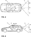
FIGS. 4 and 5 are schematic views of a correlation between portions of a camera field of view and detected eye locations of a driver of a vehicle; -
FIG. 6 is an illustrative view of a mirror assembly comprising an eye-tracking apparatus; -
FIG. 7 is a schematic view of the mirror assembly ofFIG. 6 ; and -
FIG. 8 is block diagram of a rear vision system incorporating an eye-tracking apparatus disposed in a mirror assembly in accordance with the disclosure. - For purposes of description herein the terms "upper," "lower," "right," "left," "rear," "front," "vertical," "horizontal," and derivatives thereof shall relate to the device as oriented in
FIG. 1 . However, it is to be understood that the device may assume various alternative orientations and step sequences, except where expressly specified to the contrary. It is also to be understood that the specific devices and processes illustrated in the attached drawings, and described in the following specification are simply exemplary embodiments of the inventive concepts defined in the appended claims. Hence, specific dimensions and other physical characteristics relating to the embodiments disclosed herein are not to be considered as limiting, unless the claims expressly state otherwise. - Referring now to
FIG. 1 ,reference numeral 10 indicates a rear vision system for a vehicle 12 (FIG. 2 ).System 10 includes acamera 14 capturing a field of view 16 (FIG. 4 ) rearward (e.g. in rear direction 18) of thevehicle 12 and arearview mirror 20 including adisplay substrate 22 thereon.System 10 further includes an image sensor 24 (FIG. 6 ) directed toward aninterior 26 ofvehicle 12 and configured to capture image data of an object that, in an example, may include the eyes 34 or head 36 (both the eyes 34 andhead 36 being generally indicated with respect to various identified positions thereof, designated aseyes head vehicle 12. Acontrol unit 28 is in communication with thecamera 14 to receive a first image 30 (also being generally indicated with respect to various identified areas thereof, designated asimage view 16.Control unit 28 is further coupled with theimage sensor 24 to determine a position of the object (e.g., the eyes 34 orhead 36 of the driver) within the image data and is also in communication with thedisplay substrate 22 to present a portion 32 (also being generally indicated with respect to various identified portions, designated asportion view 16. The sub-area is selected to simulate a reflected image from the field ofview 16 to the object by thedisplay substrate 22 based on the determined position of the object. - It is noted that the
control unit 28, as described herein, can be any suitable component or structure, including multiple, connected components or structures, within or associated withvehicle 12 that can receive the image 30 fromcamera 14 for presentation ondisplay 22, detect the position of an object (e.g., thehead 36 or eyes 34 of a driver), and present theportion 32 of the image 30 corresponding to the object position ondisplay 22, according to the scheme disclosed herein. By way of example,control unit 28 may be or include specific functionality within a computer system on-board vehicle 12. Further,control unit 28 may comprise dedicated computer chips (e.g., application-specific integrated circuits) respectively connected with thesensor 24 andcamera 14, and further in communication at least with each other. - Referring to
FIG. 2 , a schematic depiction is shown in which thehead 36 of a driver ofvehicle 12 is shown invarious positions rearview mirror 40. As discussed herein, such astandard rearview mirror 40 can be considered as a reflective rearview mirror that the driver uses to view a reflected image out of arear windshield 42 ofvehicle 12 and to the rear ofvehicle 12 indirection 18. As illustrated, the driver has a limited view toward the rear ofvehicle 12 that corresponds to a mirror field 44 determined by incidence lines taken from the respective eyes 34 of the driver to the corresponding edges of the reflective surface ofstandard mirror 40 and corresponding reflection lines that, according to general optics principles, are at an equal angle to the incidence lines about a plane normal to the reflective surface. In this manner, the particular mirror field 44 and the accompanying portion of the area to the rear ofvehicle 12 viewable throughstandard mirror 40 can be adjusted by changing the particular angle of thestandard mirror 40 itself or by the driver moving his or herhead 36 and, thereby, changing the angles of the incidence lines from the eyes 34 to thestandard mirror 40. - In this type of arrangement, it is common for the driver to position the
standard mirror 40 to correspond with the view that the driver would like to have available usingstandard mirror 40 when the driver'shead 36 is in a comfortable, neutral seating position. During driving, the driver may wish to view an object or the like outside of this neutral mirror field 44 and may, accordingly, move his or herhead 36, such as from aposition 36a inFIG. 1 to aposition 36b to instinctively provide a different view by an adjusted mirror field 44, such as frommirror field 44a tomirror field 44b, which is shown having moved both horizontally and vertically. In this manner, the viewable portion to the rear ofvehicle 12 usingstandard mirror 40 can be changed without changing the baseline view that the driver has when in the above-described neutral position. - In the
system 10 described above, wherein thestandard rearview mirror 40 is replaced or otherwise accompanies the above-described "display"mirror 20,control unit 28 may, as discussed above, be configured to replicate the adjustment of the image presented ondisplay 22 to correspond with the adjustment that the driver expects when moving his or herhead 36 with respect to the illustratedstandard mirror 40, while maintaining the image at a predetermined scale that matches what would be seen in a theoretical reflection based on general estimates of the driver position and of the view to the rear ofvehicle 12. As shown inFIG. 3 ,vehicle 12 includingsystem 10 can includecamera 14 positioned on the rear ofvehicle 12. In the illustrated example,camera 14 is positioned on the liftgate of thevehicle 12 beneath therear windshield 42 included therein. In alternative arrangements, thecamera 14 can be positioned within the interior ofvehicle 12, such as along the headliner of thevehicle 12 withcamera 14 adjacent to and directed out ofrear windshield 42. Still further arrangements are possible and can be schematically similar to the depiction inFIG. 3 . As illustrated,camera 14 can be configured such that the field ofview 16 thereof is greater than that of the general size of mirror field 44 that would correspond todisplay 22 if it were a standard reflective surface. As illustrated, field ofview 16 can be, for example, 90 degrees or greater, including angles of at least 120 degrees or the like. Accordingly,control unit 28 may crop the image 30 taken bycamera 14, as illustrated inFIG. 1 , such that theportion 32 of image 30 shown ondisplay 22 generally mimics how a reflected image would appear. This includes both the size of the images projected and the viewing angle of theportion 32 of image 30. - As illustrated in
FIG. 3 , atheoretical image plane 46 is shown to represent the overall image 30 taken bycamera 14 with the depicted field ofview 16. As further shown, the driver ofvehicle 12, when viewing theimage portion 32 ondisplay 22 may expect theimage portion 32 to change when the driver'shead 36 is moved, based on prior experience withstandard mirrors 40. In this manner,system 10 can accommodate the driver's expectations by tracking the position of the driver'shead 36 or, specifically, the eyes 34 of the driver with respect tomirror 20 and may pan the image 30 with respect to theportion 32 shown ondisplay 22. This accommodation is schematically depicted inFIG. 3 , wherein theportions image plane 46 correspond toexample head positions eyes display 22, such as by mapping the determined locations ofeyes position head 36, based on the same optical principles of thestandard mirror 40 depicted inFIG. 2 , which may be done using predetermined scale factors for image movement based on the distance between positions ofeyes - As shown in
FIGS. 4 and 5 , the movement of image 30 with respect to theportion 32 thereof shown ondisplay 22 can be independent of the positioning ofmirror 20. Instead, theportion 32 can be based on a baseline image that can be predetermined and stored in memory 70 (FIG. 8 ) at the time of manufacture, for example. In this manner, theposition eyes head 36 at, for example, the time of activation ofsystem 10 can be established and correlated with abaseline portion 32a of image 30 that corresponds to, for example, a directly rearward 18 view within the field ofview 16. In the example shown inFIG. 1 , for example, aninput 54 can be provided to allow the driver to adjust the baseline image according to needs or desires. In a further example, such a baseline image can correspond with a particular estimated field ofview 16 of an average driver at a neutral (i.e. aligning with the longitudinal axis of vehicle 12) position ofmirror 20. In such an embodiment,system 10 can track the movement ofmirror 20, itself, communicating such movement (or the absolute position thereof) to controlunit 28 that can adjust the displayedportion 32 of image 30 based on such movement, in a way determined to mimic the movement of a reflective mirror. Such tracking can be done by positioning a marker within theinterior 26 ofvehicle 12 that can be located using sensor 24 (when included in mirror 20) or using a magnetic or mechanical sensor embedded in the mounting structure ofmirror 20 that facilitates movement thereof. In an embodiment when a marker is positioned ininterior 26 ofvehicle 12, thecontrol unit 28 may be able to usehead 36 or eye 34 tracking in combination with the tracking of the marker relative to theimage sensor 24 to determine the desiredimage portion 32 directly. -
System 10 can continue to track the location of thehead 36 or eyes 34 and can pan the image 30 with respect to the displayedportion 32 according to movement thereof to correspond with an expected movement based on optical principles, as discussed above. As shown, such movement can be both horizontal and vertical and can be generally opposite the movement of the eyes 34. The movement can be calibrated in advance and/or can be adjustable by the driver. In certain modes of use, the vertical tracking shown inFIG. 5 may present advantages over static displays due, at least in part, to the short aspect-ratio of theportion 32 of image 30 presented on display 22 (due to thedisplay 22 typically being wider than it is tall). For example, the tracking functionality disclosed herein may allow the driver to move or tilt his or herhead 36 upward, such as by raising his or her seat withinvehicle 12. In such an example, theportion 32 of image 30 would pan downwardly to allow the driver, for example, to view an area immediately behind the vehicle 12 (such as adjacent the rear bumper). It is noted, that such a position may not be visible using a standardreflective rearview mirror 40, as the view would be blocked by the trunk area or rear deck, depending on the vehicle type. To further achieve such a point-of-view, a second camera can be included, for example, within the rear bumper or adjacent the license plate ofvehicle 12. Such a camera may be particularly useful whencamera 14 is adjacent the headliner ofvehicle 12 to remove distortion. In such a multi-camera arrangement,control unit 28 can employ an image stitching function, algorithm, or the like to provide smooth transitioning between the respective camera images to still effectively present a single image 30 for panning in the above-described manner. In either example, when thehead 36 or eyes 34 of the driver move back toward the original position,control unit 28 will pan theportion 32 of image 30 back toward the portion that corresponds with the neutral viewing position. - In the embodiment depicted in
FIG. 1 , thesensor 24 can be included inmirror 20. In such an arrangement, the position of the eyes 34 may vary depending on the orientation ofmirror 20. In various embodiments, themirror 20 may have a reflective, partially transparent surfaceoverlying display 22 so thatmirror 20 can be used as astandard mirror 40 when, for example,display 22 is inactive. In this manner, the user may adjustmirror 20 to provide the desired baseline view prior to activation ofdisplay 22, meaning that the predetermined baseline image, as well as the position of eyes 34 detected bysensor 24 may closely correspond with the preselectedportion 32 of image 30 presented ondisplay 22 or a previously-adjusted variation thereof. In a further example, activation ofdisplay 22 can correspond with upward tilting ofdisplay 22 to reduce competition of the actual reflected image.Control unit 28 may compensate for such adjustment in the selection of theportion 32 of image 30 presented ondisplay 22. - In a variation,
sensor 24 may be located elsewhere invehicle 12, such as in an overhead consoleadjacent mirror 20 or the like. In such an embodiment, theportion 32 of image 30 selected based on the detected position of eyes 34 may be independent of the mirror position. Accordingly,system 10 may also be configured to determine the position ofmirror 20, particularly ofdisplay 22 thereof, to correlate theportion 32 of image 30 to the detected position ofdisplay 22. In an example, this tracking can be done using various mechanical or magnetic sensors, as discussed above. In this manner, as discussed above, the diver may be able to physically movemirror 20 to change thebaseline portion 32 of image 30 presented ondisplay 22, thereby removing a need for aninput 54. Additional variations are also possible, whereinmirror 20 may include asensor 24 therein and may also incorporate monitoring of the position ofdisplay 22 to provide similar adjustment and responsiveness. - The tracking functionality may utilize an infrared illumination of the area viewable by
sensor 24. In one example, thecontrol unit 28 may be able to identify a "blob" that, based on various criteria, can be reasonably identified as thehead 36 of the driver (i.e. based on general size and location criteria). As discussed above, the location of the eyes 34 can be inferred based on the head 36 location determined based on the blob detection. Again, the eye 34 position can be based on average eye 34 location relative to the identifiedhead 36 and may scale for the size of the detected blob. Alternatively, the irises of the driver's eyes 34 may be specifically identified based on a specific reflection pattern and/or location principles similar to the blob detection noted above forhead 36 identification. Such illumination may be optimized in conditions allowing for a high optical transmittance in the near infrared (NIR) range. In some embodiments, the disclosure may provide for apanel comprising display 22 that may have a high light transmittance in the NIR range, for example wavelengths ranging from 810 nm to 850 nm in the optical spectrum, along at least a portion thereof. Additionally, in some implementations, themirror 20 assembly may comprise a plurality of light sources 58 configured to illuminate at least one iris of the operator of the vehicle. - As shown in
FIG. 6 , to provide for the tracking function,sensor 24 may be disposed proximate a rear (interior) surface of thedisplay 22. Theimage sensor 24 may correspond to, for example, a digital charge-coupled device (CCD) or complementary metal-oxide-semiconductor (CMOS) active pixel sensor, although it is not meant to be limited to these example devices. In the illustrated example, thesensor 24 may be in communication with at least one light source 58, which may correspond to one or more infrared emitters configured to output an emission of light in the NIR range. In this configuration,control unit 28 or thesensor 24 may be configured to selectively activate the one or more infrared emitters corresponding to the at least one light source 58 to provide illumination such that an instantaneous location of thehead 36 or eyes 34 may be determined and/or monitored. Alternatively,sensor 24 may be a "passive" sensor in that it does not require illumination. In one example,sensor 24 can be a heat sensor that can be used to track thehead 36 of the driver. In such an embodiment, the light source 58, discussed above, may not be included insystem 10. - When present, the infrared emitters or the light sources 58 may correspond to a plurality of infrared emitter banks 60. Each of the infrared emitter banks 60,62 may comprise a plurality of light emitting diodes, which may be grouped in a matrix or otherwise grouped and disposed behind the rear surface of the
display 22. In an embodiment, the plurality of light sources 58 may correspond to a first emitter bank 60 and a second emitter bank 62. The first emitter bank 60 may be configured to output the emission in the NIR range from a first side portion of the front (outside) surface of thedisplay 22. The second emitter bank 62 may be configured to output the emission in the NIR range from a second side portion of the front surface of thedisplay 22. In this configuration, thesystem 10 may be configured to illuminate the eyes 34 of the driver such that thesensor 24 may discern the eyes 34 of the driver from within the image data received fromsensor 24. - In an embodiment, each of the first emitter bank 60 and/or the second emitter bank 62 may correspond to more or fewer LEDs or banks of LEDs. In some embodiments comprising a variation of
display 22 having a high level of transmittance in the NIR range at least in portion(s) overlying emitter banks 60,62,system 10 may utilize fewer or less intense LEDs. In some embodiments comprising a variation ofdisplay 22 having a lower level of transmittance in the NIR range, thesystem 10 may utilize a greater number of or more intense LEDs. -
Sensor 24 may be disposed on acircuit 56, for example a printed circuit board in communication withcontrol unit 28.Control unit 28 may further be in communication with various devices that may be incorporated in thevehicle 12 via thecommunication bus 66 or any other suitable communication interface.Control unit 28 may correspond to one or more processors or circuits, which may be configured to process image data received fromsensor 24. In this configuration, the image data may be communicated fromsensor 24 to controlunit 28. Thecontrol unit 28 may process the image data with one or more algorithms configured to discern or otherwise identify the eyes 34 of the driver within the image data. Further detailed discussion of thecontrol unit 28 and the various devices that may be in communication therewith are discussed in reference toFIG. 8 . - The
control unit 28 may further be in communication withdisplay 22. Thecontrol unit 28 may be operable to display the image data received fromcamera 14, as discussed above, such that the driver may view theportion 32 of the image 30 received fromcamera 14. As further discussed above,display 22 may correspond to a partial or full display mirror configured to display theportion 32 of the video image 30 through at least a portion of themirror assembly 20. Thedisplay 22 may be constructed utilizing various technologies, for example LCD, LED, OLED, plasma, DLP or other display technology. Examples of display assemblies that may be utilized with the disclosure may includeU.S. Patent Nos. 6,572,233 "REARVIEW DISPLAY MIRROR,"8,237,909 "VEHICULAR REARVIEW MIRROR ASSEMBLY INCLUDING INTEGRATED BACKLIGHTING FOR A LIQUID CRYSTAL DISPLAY (LCD)," 8,411,245 "MULTI-DISPLAY MIRROR SYSTEM AND METHOD FOR EXPANDED VIEW AROUND A VEHICLE," and 8,339,526 "VEHICLE REARVIEW MIRROR ASSEMBLY INCLUDING A HIGH INTENSITY DISPLAY." - Referring to
FIG. 8 , a block diagram ofsystem 10 with additional components of overall control system ofvehicle 12 is shown. Thecontrol unit 28 is shown in communication withmirror 20, including sensor 24 (FIG .6 ), and thecamera 14 and may also be in communication with thevehicle control module 64 via acommunication bus 66 of thevehicle 12. Thecommunication bus 66 may be configured to deliver signals to thecontrol unit 28 identifying various vehicle states. For example, thecommunication bus 66 may be configured to communicate to the control unit 28 a drive selection of the vehicle, an ignition state, a door open or ajar status, or the like. Such information and control signals may be utilized by thecontrol unit 28 to activate or adjust various states and/or control schemes of thesystem 10 and/or themirror assembly 20. - The
control unit 28 may comprise aprocessor 68 having one or more circuits configured to receive the signals from thecommunication bus 66 and control thesystem 10. Theprocessor 68 may be in communication with amemory 70 configured to store instructions to control operations of thesystem 10. For example, thecontrol unit 28 may be configured to store one or more characteristics or profiles utilized by thecontrol unit 28 to identify the eyes 34 of the driver of thevehicle 12 within the image data. - The
control unit 28 may further be in communication withcamera 14. Thecontrol unit 28 may receive image data fromcamera 14, as discussed further above. In this manner, based on the identification of the eyes 34, thecontrol unit 28 may be configured to select a correspondingportion 32 of the video image 30 to present ondisplay 22 and to smoothly pan the image 30 with respect to theportion 32, if necessary. Thecontrol unit 28 may further be in communication with one or more of agauge cluster 74, an audio/video (A/V)system 76, aninfotainment system 78, a media center, a vehicle computing system, and/or various other devices or systems of the vehicle. In various embodiments, thecontrol unit 28 may also display the video image 30 fromcamera 14 on the devices 74-78, including an un-cropped image 30. - In a further embodiment, the
control unit 28 may correspond to one of more processors or circuits and may be configured to further process the image data received fromsensor 24. In this configuration, thecontrol unit 28 may process the image data with one or more algorithms configured to determine an identity of the operator of the vehicle. With the identity of the operator or one or more passengers of the vehicle identified, thecontrol unit 28 may further be operable to control various systems or functions of the vehicle. - The
control unit 28 may further be in communication with an ambientlight sensor 82. The ambientlight sensor 82 may be operable to communicate a light condition, for example a level brightness or intensity of the ambient light proximate the vehicle. In response to the level of the ambient light, thecontrol unit 28 may be configured to adjust a light intensity output from thedisplay 22. In this configuration, the operator of thecontrol unit 28 may adjust the brightness of thedisplay 22. - The
control unit 28 may further be in communication with aninterface 84 configured to receive one or more inputs configured to control aspects ofsystem 10. In some embodiments, theinterface 84 may be combined with one or more devices of the vehicle. For example, theinterface 84 may form a portion of thegauge cluster 74, the A/V system 76, theinfotainment system 78, a display console and/or various input/output devices that may commonly be utilized in automotive vehicles (e.g. a steering switch, steering wheel controls, etc.). In this way, the disclosure provides for various control schemes for usingsystem 10 invehicle 12. In one example, theinput 54 depicted inFIG. 1 can be presented graphically on one of these devices. - It will be understood that any described processes or steps within described processes may be combined with other disclosed processes or steps to form structures within the scope of the present device. The exemplary structures and processes disclosed herein are for illustrative purposes and are not to be construed as limiting.
- It is also to be understood that variations and modifications can be made on the aforementioned structures and methods without departing from the concepts of the present device, and further it is to be understood that such concepts are intended to be covered by the following claims unless these claims by their language expressly state otherwise.
- The above description is considered that of the illustrated embodiments only. Modifications of the device will occur to those skilled in the art and to those who make or use the device. Therefore, it is understood that the embodiments shown in the drawings and described above is merely for illustrative purposes and not intended to limit the scope of the device, which is defined by the following claims as interpreted according to the principles of patent law, including the Doctrine of Equivalents.
Claims (14)
- A rear vision system (10) for a vehicle (12), comprising:a camera (14) mounted with the vehicle (12) and capturing a field of view (16) of a first area rearward of the vehicle (12);a rearview mirror (20) including a display substrate (22) thereon;an image (30) sensor (24) directed toward an interior (26) of the vehicle (12) and configured to capture image (30) data of an object; anda controller (28):in communication with the camera (14) and receiving a first video image (30) of the first area corresponding with the field of view (16);in communication with the image (30) sensor (24) to determine a position of the object within the image (30) data; andin communication with the display substrate (22) to present a sub-area (32) of the first area on the display substrate (22), the sub-area (32) being selected to simulate a reflected image (30) from the field of view (16) to the object by the substrate (22) based on the determined position of the object.
- The rear vision system (10) of claim 1 or 2, wherein the object is a pair of eyes (34) of a driver of the vehicle (12).
- The rear vision system (10) of any of claims 1 to 3, wherein the sub-area (32) of the first video image (30) is selected to correspond with an estimated sub-area (32) of the field of view (16) based on the determined position of the object by panning the first image (30) with respect to the sub-area (32) based on a movement of the object from a baseline position.
- The rear vision system (10) of claim 3, wherein the object is panned based on a predetermined scale to correlate with a scale between an estimated distance from the rearview mirror (20) to the object and an estimated distance from the rearview mirror (20) to a theoretical image (30) plane to the rear of the vehicle (12).
- The rear vision system (10) of claim 4, wherein the estimated distance from the rearview mirror (20) to the object is fixed.
- The rear vision system (10) of claims 3 or 4, wherein a baseline position of the first image (30) with respect to the portion can be adjusted by a user.
- The rear vision system (10) of any of the preceding claims, wherein the image (30) sensor (24) is included within the rearview mirror (20).
- The rear vision system (10) of any of the preceding claims, further including a light source (58) directed toward an interior (26) of the vehicle (12) and configured for illuminating a portion of the object.
- The rear vision system (10) of claim 8, wherein the light source (58) is configured to emit light in a near infrared (NIR) range.
- The rear vision system (10) of any of the preceding claims, wherein the sub-area (32) is scaled to generally match a scale of a theoretical reflected image (30) of the field of view (16) by the substrate (22) to the object.
- The rear vision system (10) of any of the preceding claims, wherein the controller (28) is further communication with the image (30) sensor (24) to locate the object within the image (30) data and to determine a position of the object relative to a predetermined two-dimensional coordinate system (10) along a theoretical viewing distance from the substrate (22)
- The rear vision system (10) of claim 11, wherein the sub-area (32) is selected to simulate a reflected image (30) from the field of view (16) to the object by the substrate (22) based on the determined position of the object by correlating the position of the object with a two-dimensional coordinate system (10) assigned to the first area based on a scale between a theoretical viewing distance and a predetermined estimated image (30) distance from the display substrate (22) to a theoretical image (30) plane to the rear of the vehicle (12).
- The rear vision system (10) of claim 12, wherein the theoretical viewing distance is fixed.
- A vehicle (12), comprising:
the rear vision system (10) of any of the preceding claims.
Applications Claiming Priority (2)
| Application Number | Priority Date | Filing Date | Title |
|---|---|---|---|
| US201662439181P | 2016-12-27 | 2016-12-27 | |
| PCT/US2017/068427 WO2018125870A1 (en) | 2016-12-27 | 2017-12-26 | Rear vision system with eye-tracking |
Publications (3)
| Publication Number | Publication Date |
|---|---|
| EP3562708A4 EP3562708A4 (en) | 2019-11-06 |
| EP3562708A1 EP3562708A1 (en) | 2019-11-06 |
| EP3562708B1 true EP3562708B1 (en) | 2021-02-17 |
Family
ID=62625458
Family Applications (1)
| Application Number | Title | Priority Date | Filing Date |
|---|---|---|---|
| EP17888325.2A Active EP3562708B1 (en) | 2016-12-27 | 2017-12-26 | Rear vision system with eye-tracking |
Country Status (6)
| Country | Link |
|---|---|
| US (1) | US10525890B2 (en) |
| EP (1) | EP3562708B1 (en) |
| JP (1) | JP6906055B2 (en) |
| KR (1) | KR102464874B1 (en) |
| CN (1) | CN109937158B (en) |
| WO (1) | WO2018125870A1 (en) |
Cited By (1)
| Publication number | Priority date | Publication date | Assignee | Title |
|---|---|---|---|---|
| WO2023152729A1 (en) * | 2022-02-14 | 2023-08-17 | Gentex Corporation | Imaging system for a vehicle |
Families Citing this family (8)
| Publication number | Priority date | Publication date | Assignee | Title |
|---|---|---|---|---|
| USD845851S1 (en) * | 2016-03-31 | 2019-04-16 | Gentex Corporation | Rearview device |
| US10699143B2 (en) * | 2017-03-10 | 2020-06-30 | Gentex Corporation | System and method for vehicle occupant identification and monitoring |
| US11203295B2 (en) * | 2017-04-14 | 2021-12-21 | Panasonic Automotive Svstems Company of America, Division of Panasonic Corporation of North America | Rearview head up display |
| US20180304814A1 (en) * | 2017-04-24 | 2018-10-25 | Panasonic Automotive Systems Company Of America, Division Of Panasonic Corporation Of North America | Rear view mirror-like perspective change system and method |
| WO2019216087A1 (en) * | 2018-05-08 | 2019-11-14 | ソニーセミコンダクタソリューションズ株式会社 | Image processing device, moving machine, and method, and program |
| TWI637289B (en) * | 2018-05-18 | 2018-10-01 | 緯創資通股份有限公司 | Eye tracking-based display control system |
| EP3871146A4 (en) * | 2018-12-10 | 2021-12-29 | Gentex Corporation | Scanning apparatus for reducing field of view search space |
| KR20220055541A (en) | 2020-10-26 | 2022-05-04 | 현대자동차주식회사 | Vehicle and method for controlling thereof |
Family Cites Families (20)
| Publication number | Priority date | Publication date | Assignee | Title |
|---|---|---|---|---|
| US5289321A (en) | 1993-02-12 | 1994-02-22 | Secor James O | Consolidated rear view camera and display system for motor vehicle |
| FR2773521B1 (en) * | 1998-01-15 | 2000-03-31 | Carlus Magnus Limited | METHOD AND DEVICE FOR CONTINUOUSLY MONITORING THE DRIVER'S VIGILANCE STATE OF A MOTOR VEHICLE, IN ORDER TO DETECT AND PREVENT A POSSIBLE TREND AS IT GOES TO SLEEP |
| EP2309453A3 (en) * | 1998-07-31 | 2012-09-26 | Panasonic Corporation | Image displaying apparatus and image displaying method |
| US7581859B2 (en) * | 2005-09-14 | 2009-09-01 | Donnelly Corp. | Display device for exterior rearview mirror |
| US20040027694A1 (en) | 2002-08-06 | 2004-02-12 | Mediaview Technologies Corporation | Adjustable segmented dual function mirror with video display |
| US7561966B2 (en) * | 2003-12-17 | 2009-07-14 | Denso Corporation | Vehicle information display system |
| JP4323377B2 (en) * | 2004-05-24 | 2009-09-02 | オリンパス株式会社 | Image display device |
| JP5235876B2 (en) | 2006-06-28 | 2013-07-10 | ジョンソン コントロールズ テクノロジー カンパニー | Vehicle vision system |
| CN101164805B (en) * | 2007-06-06 | 2010-12-01 | 北京理工大学 | Automobile envisaging display system |
| JP5115136B2 (en) * | 2007-10-16 | 2013-01-09 | 株式会社デンソー | Vehicle rear monitoring device |
| US20100020170A1 (en) | 2008-07-24 | 2010-01-28 | Higgins-Luthman Michael J | Vehicle Imaging System |
| US8411245B2 (en) | 2009-02-06 | 2013-04-02 | Gentex Corporation | Multi-display mirror system and method for expanded view around a vehicle |
| JP2012195634A (en) * | 2011-03-15 | 2012-10-11 | Panasonic Corp | Vehicle rearview visual-recognition apparatus |
| JP5645769B2 (en) * | 2011-08-01 | 2014-12-24 | 株式会社日立製作所 | Image processing device |
| US9242602B2 (en) | 2012-08-27 | 2016-01-26 | Fotonation Limited | Rearview imaging systems for vehicle |
| KR101417383B1 (en) | 2012-10-31 | 2014-07-08 | 현대자동차주식회사 | Apparatus and method for image control of room-mirror |
| KR101655818B1 (en) * | 2014-12-11 | 2016-09-08 | 현대자동차주식회사 | Wearable glass, control method thereof and vehicle control system |
| JP2016149651A (en) * | 2015-02-12 | 2016-08-18 | 株式会社デンソー | Display controller and display system |
| US20160297362A1 (en) | 2015-04-09 | 2016-10-13 | Ford Global Technologies, Llc | Vehicle exterior side-camera systems and methods |
| US10589676B2 (en) * | 2016-06-02 | 2020-03-17 | Magna Electronics Inc. | Vehicle display system with user input display |
-
2017
- 2017-12-26 WO PCT/US2017/068427 patent/WO2018125870A1/en unknown
- 2017-12-26 EP EP17888325.2A patent/EP3562708B1/en active Active
- 2017-12-26 JP JP2019535238A patent/JP6906055B2/en active Active
- 2017-12-26 KR KR1020197015987A patent/KR102464874B1/en active IP Right Grant
- 2017-12-26 US US15/854,370 patent/US10525890B2/en active Active
- 2017-12-26 CN CN201780068812.1A patent/CN109937158B/en active Active
Non-Patent Citations (1)
| Title |
|---|
| None * |
Cited By (1)
| Publication number | Priority date | Publication date | Assignee | Title |
|---|---|---|---|---|
| WO2023152729A1 (en) * | 2022-02-14 | 2023-08-17 | Gentex Corporation | Imaging system for a vehicle |
Also Published As
| Publication number | Publication date |
|---|---|
| JP2020515449A (en) | 2020-05-28 |
| EP3562708A4 (en) | 2019-11-06 |
| CN109937158B (en) | 2022-03-22 |
| EP3562708A1 (en) | 2019-11-06 |
| CN109937158A (en) | 2019-06-25 |
| JP6906055B2 (en) | 2021-07-21 |
| KR102464874B1 (en) | 2022-11-09 |
| WO2018125870A1 (en) | 2018-07-05 |
| KR20190102184A (en) | 2019-09-03 |
| US10525890B2 (en) | 2020-01-07 |
| US20180178729A1 (en) | 2018-06-28 |
Similar Documents
| Publication | Publication Date | Title |
|---|---|---|
| EP3562708B1 (en) | Rear vision system with eye-tracking | |
| US10315573B2 (en) | Method for displaying information to vehicle driver | |
| US20190381938A1 (en) | Rearview mirror assembly having automatic adjustment responsive to eye-tracking | |
| US10908417B2 (en) | Vehicle vision system with virtual retinal display | |
| US11964613B2 (en) | Interior trim part of motor vehicle with thin-film display device | |
| US7423522B2 (en) | Tire pressure alert system | |
| US20140285666A1 (en) | Vision system with door mounted exterior mirror and display | |
| JP5983693B2 (en) | Mirror device with display function and display switching method | |
| US11930264B2 (en) | Vehicular driver monitoring system with camera view optimization | |
| US20230302994A1 (en) | Vehicular interior cabin lighting system selectively operable for dms and oms functions | |
| JP2016055782A5 (en) | ||
| JP6585662B2 (en) | Vehicle roof mounting system | |
| US20230078512A1 (en) | Overhead console accessory system with shared controls, cameras, and lighting | |
| WO2016018320A1 (en) | System for projecting an image within a vehicle interior | |
| JP6229769B2 (en) | Mirror device with display function and display switching method | |
| US20170299861A1 (en) | Display unit for vehicle head-up display system | |
| US10432891B2 (en) | Vehicle head-up display system | |
| US20230286441A1 (en) | Vehicular overhead console integrated with interior mirror and electronic content | |
| US20240100946A1 (en) | Occupant imaging device | |
| US20230256908A1 (en) | Imaging system for a vehicle | |
| JP2018002152A (en) | Mirror device with display function and display switching method | |
| JP2019001293A (en) | On-vehicle display device | |
| CN117940316A (en) | In-vehicle cabin monitoring system with light emitters selectively operated for DMS and OMS functions | |
| WO2023220222A1 (en) | Vehicular driver monitoring system with driver monitoring camera and near ir light emitter at interior rearview mirror assembly | |
| KR20150108590A (en) | Apparatus for controlling mirror in vehivle |
Legal Events
| Date | Code | Title | Description |
|---|---|---|---|
| STAA | Information on the status of an ep patent application or granted ep patent |
Free format text: STATUS: THE INTERNATIONAL PUBLICATION HAS BEEN MADE |
|
| PUAI | Public reference made under article 153(3) epc to a published international application that has entered the european phase |
Free format text: ORIGINAL CODE: 0009012 |
|
| STAA | Information on the status of an ep patent application or granted ep patent |
Free format text: STATUS: REQUEST FOR EXAMINATION WAS MADE |
|
| 17P | Request for examination filed |
Effective date: 20190718 |
|
| A4 | Supplementary search report drawn up and despatched |
Effective date: 20190917 |
|
| AK | Designated contracting states |
Kind code of ref document: A1 Designated state(s): AL AT BE BG CH CY CZ DE DK EE ES FI FR GB GR HR HU IE IS IT LI LT LU LV MC MK MT NL NO PL PT RO RS SE SI SK SM TR |
|
| AX | Request for extension of the european patent |
Extension state: BA ME |
|
| DAV | Request for validation of the european patent (deleted) | ||
| DAX | Request for extension of the european patent (deleted) | ||
| GRAP | Despatch of communication of intention to grant a patent |
Free format text: ORIGINAL CODE: EPIDOSNIGR1 |
|
| STAA | Information on the status of an ep patent application or granted ep patent |
Free format text: STATUS: GRANT OF PATENT IS INTENDED |
|
| INTG | Intention to grant announced |
Effective date: 20200903 |
|
| GRAS | Grant fee paid |
Free format text: ORIGINAL CODE: EPIDOSNIGR3 |
|
| GRAA | (expected) grant |
Free format text: ORIGINAL CODE: 0009210 |
|
| STAA | Information on the status of an ep patent application or granted ep patent |
Free format text: STATUS: THE PATENT HAS BEEN GRANTED |
|
| AK | Designated contracting states |
Kind code of ref document: B1 Designated state(s): AL AT BE BG CH CY CZ DE DK EE ES FI FR GB GR HR HU IE IS IT LI LT LU LV MC MK MT NL NO PL PT RO RS SE SI SK SM TR |
|
| REG | Reference to a national code |
Ref country code: GB Ref legal event code: FG4D |
|
| REG | Reference to a national code |
Ref country code: CH Ref legal event code: EP |
|
| REG | Reference to a national code |
Ref country code: DE Ref legal event code: R096 Ref document number: 602017033017 Country of ref document: DE |
|
| REG | Reference to a national code |
Ref country code: AT Ref legal event code: REF Ref document number: 1361061 Country of ref document: AT Kind code of ref document: T Effective date: 20210315 |
|
| REG | Reference to a national code |
Ref country code: IE Ref legal event code: FG4D |
|
| REG | Reference to a national code |
Ref country code: LT Ref legal event code: MG9D |
|
| REG | Reference to a national code |
Ref country code: NL Ref legal event code: MP Effective date: 20210217 |
|
| PG25 | Lapsed in a contracting state [announced via postgrant information from national office to epo] |
Ref country code: NO Free format text: LAPSE BECAUSE OF FAILURE TO SUBMIT A TRANSLATION OF THE DESCRIPTION OR TO PAY THE FEE WITHIN THE PRESCRIBED TIME-LIMIT Effective date: 20210517 Ref country code: PT Free format text: LAPSE BECAUSE OF FAILURE TO SUBMIT A TRANSLATION OF THE DESCRIPTION OR TO PAY THE FEE WITHIN THE PRESCRIBED TIME-LIMIT Effective date: 20210617 Ref country code: GR Free format text: LAPSE BECAUSE OF FAILURE TO SUBMIT A TRANSLATION OF THE DESCRIPTION OR TO PAY THE FEE WITHIN THE PRESCRIBED TIME-LIMIT Effective date: 20210518 Ref country code: FI Free format text: LAPSE BECAUSE OF FAILURE TO SUBMIT A TRANSLATION OF THE DESCRIPTION OR TO PAY THE FEE WITHIN THE PRESCRIBED TIME-LIMIT Effective date: 20210217 Ref country code: HR Free format text: LAPSE BECAUSE OF FAILURE TO SUBMIT A TRANSLATION OF THE DESCRIPTION OR TO PAY THE FEE WITHIN THE PRESCRIBED TIME-LIMIT Effective date: 20210217 Ref country code: LT Free format text: LAPSE BECAUSE OF FAILURE TO SUBMIT A TRANSLATION OF THE DESCRIPTION OR TO PAY THE FEE WITHIN THE PRESCRIBED TIME-LIMIT Effective date: 20210217 Ref country code: BG Free format text: LAPSE BECAUSE OF FAILURE TO SUBMIT A TRANSLATION OF THE DESCRIPTION OR TO PAY THE FEE WITHIN THE PRESCRIBED TIME-LIMIT Effective date: 20210517 |
|
| REG | Reference to a national code |
Ref country code: AT Ref legal event code: MK05 Ref document number: 1361061 Country of ref document: AT Kind code of ref document: T Effective date: 20210217 |
|
| PG25 | Lapsed in a contracting state [announced via postgrant information from national office to epo] |
Ref country code: RS Free format text: LAPSE BECAUSE OF FAILURE TO SUBMIT A TRANSLATION OF THE DESCRIPTION OR TO PAY THE FEE WITHIN THE PRESCRIBED TIME-LIMIT Effective date: 20210217 Ref country code: NL Free format text: LAPSE BECAUSE OF FAILURE TO SUBMIT A TRANSLATION OF THE DESCRIPTION OR TO PAY THE FEE WITHIN THE PRESCRIBED TIME-LIMIT Effective date: 20210217 Ref country code: LV Free format text: LAPSE BECAUSE OF FAILURE TO SUBMIT A TRANSLATION OF THE DESCRIPTION OR TO PAY THE FEE WITHIN THE PRESCRIBED TIME-LIMIT Effective date: 20210217 Ref country code: PL Free format text: LAPSE BECAUSE OF FAILURE TO SUBMIT A TRANSLATION OF THE DESCRIPTION OR TO PAY THE FEE WITHIN THE PRESCRIBED TIME-LIMIT Effective date: 20210217 Ref country code: SE Free format text: LAPSE BECAUSE OF FAILURE TO SUBMIT A TRANSLATION OF THE DESCRIPTION OR TO PAY THE FEE WITHIN THE PRESCRIBED TIME-LIMIT Effective date: 20210217 |
|
| PG25 | Lapsed in a contracting state [announced via postgrant information from national office to epo] |
Ref country code: IS Free format text: LAPSE BECAUSE OF FAILURE TO SUBMIT A TRANSLATION OF THE DESCRIPTION OR TO PAY THE FEE WITHIN THE PRESCRIBED TIME-LIMIT Effective date: 20210617 |
|
| PG25 | Lapsed in a contracting state [announced via postgrant information from national office to epo] |
Ref country code: EE Free format text: LAPSE BECAUSE OF FAILURE TO SUBMIT A TRANSLATION OF THE DESCRIPTION OR TO PAY THE FEE WITHIN THE PRESCRIBED TIME-LIMIT Effective date: 20210217 Ref country code: CZ Free format text: LAPSE BECAUSE OF FAILURE TO SUBMIT A TRANSLATION OF THE DESCRIPTION OR TO PAY THE FEE WITHIN THE PRESCRIBED TIME-LIMIT Effective date: 20210217 Ref country code: AT Free format text: LAPSE BECAUSE OF FAILURE TO SUBMIT A TRANSLATION OF THE DESCRIPTION OR TO PAY THE FEE WITHIN THE PRESCRIBED TIME-LIMIT Effective date: 20210217 Ref country code: SM Free format text: LAPSE BECAUSE OF FAILURE TO SUBMIT A TRANSLATION OF THE DESCRIPTION OR TO PAY THE FEE WITHIN THE PRESCRIBED TIME-LIMIT Effective date: 20210217 |
|
| REG | Reference to a national code |
Ref country code: DE Ref legal event code: R097 Ref document number: 602017033017 Country of ref document: DE |
|
| PG25 | Lapsed in a contracting state [announced via postgrant information from national office to epo] |
Ref country code: SK Free format text: LAPSE BECAUSE OF FAILURE TO SUBMIT A TRANSLATION OF THE DESCRIPTION OR TO PAY THE FEE WITHIN THE PRESCRIBED TIME-LIMIT Effective date: 20210217 Ref country code: DK Free format text: LAPSE BECAUSE OF FAILURE TO SUBMIT A TRANSLATION OF THE DESCRIPTION OR TO PAY THE FEE WITHIN THE PRESCRIBED TIME-LIMIT Effective date: 20210217 Ref country code: RO Free format text: LAPSE BECAUSE OF FAILURE TO SUBMIT A TRANSLATION OF THE DESCRIPTION OR TO PAY THE FEE WITHIN THE PRESCRIBED TIME-LIMIT Effective date: 20210217 |
|
| PLBE | No opposition filed within time limit |
Free format text: ORIGINAL CODE: 0009261 |
|
| STAA | Information on the status of an ep patent application or granted ep patent |
Free format text: STATUS: NO OPPOSITION FILED WITHIN TIME LIMIT |
|
| 26N | No opposition filed |
Effective date: 20211118 |
|
| PG25 | Lapsed in a contracting state [announced via postgrant information from national office to epo] |
Ref country code: AL Free format text: LAPSE BECAUSE OF FAILURE TO SUBMIT A TRANSLATION OF THE DESCRIPTION OR TO PAY THE FEE WITHIN THE PRESCRIBED TIME-LIMIT Effective date: 20210217 Ref country code: ES Free format text: LAPSE BECAUSE OF FAILURE TO SUBMIT A TRANSLATION OF THE DESCRIPTION OR TO PAY THE FEE WITHIN THE PRESCRIBED TIME-LIMIT Effective date: 20210217 |
|
| PG25 | Lapsed in a contracting state [announced via postgrant information from national office to epo] |
Ref country code: SI Free format text: LAPSE BECAUSE OF FAILURE TO SUBMIT A TRANSLATION OF THE DESCRIPTION OR TO PAY THE FEE WITHIN THE PRESCRIBED TIME-LIMIT Effective date: 20210217 |
|
| PG25 | Lapsed in a contracting state [announced via postgrant information from national office to epo] |
Ref country code: IT Free format text: LAPSE BECAUSE OF FAILURE TO SUBMIT A TRANSLATION OF THE DESCRIPTION OR TO PAY THE FEE WITHIN THE PRESCRIBED TIME-LIMIT Effective date: 20210217 |
|
| PG25 | Lapsed in a contracting state [announced via postgrant information from national office to epo] |
Ref country code: IS Free format text: LAPSE BECAUSE OF FAILURE TO SUBMIT A TRANSLATION OF THE DESCRIPTION OR TO PAY THE FEE WITHIN THE PRESCRIBED TIME-LIMIT Effective date: 20210617 |
|
| PG25 | Lapsed in a contracting state [announced via postgrant information from national office to epo] |
Ref country code: MC Free format text: LAPSE BECAUSE OF FAILURE TO SUBMIT A TRANSLATION OF THE DESCRIPTION OR TO PAY THE FEE WITHIN THE PRESCRIBED TIME-LIMIT Effective date: 20210217 |
|
| REG | Reference to a national code |
Ref country code: CH Ref legal event code: PL |
|
| REG | Reference to a national code |
Ref country code: BE Ref legal event code: MM Effective date: 20211231 |
|
| PG25 | Lapsed in a contracting state [announced via postgrant information from national office to epo] |
Ref country code: LU Free format text: LAPSE BECAUSE OF NON-PAYMENT OF DUE FEES Effective date: 20211226 Ref country code: IE Free format text: LAPSE BECAUSE OF NON-PAYMENT OF DUE FEES Effective date: 20211226 |
|
| PG25 | Lapsed in a contracting state [announced via postgrant information from national office to epo] |
Ref country code: BE Free format text: LAPSE BECAUSE OF NON-PAYMENT OF DUE FEES Effective date: 20211231 |
|
| PG25 | Lapsed in a contracting state [announced via postgrant information from national office to epo] |
Ref country code: LI Free format text: LAPSE BECAUSE OF NON-PAYMENT OF DUE FEES Effective date: 20211231 Ref country code: CH Free format text: LAPSE BECAUSE OF NON-PAYMENT OF DUE FEES Effective date: 20211231 |
|
| P01 | Opt-out of the competence of the unified patent court (upc) registered |
Effective date: 20230503 |
|
| PG25 | Lapsed in a contracting state [announced via postgrant information from national office to epo] |
Ref country code: CY Free format text: LAPSE BECAUSE OF FAILURE TO SUBMIT A TRANSLATION OF THE DESCRIPTION OR TO PAY THE FEE WITHIN THE PRESCRIBED TIME-LIMIT Effective date: 20210217 |
|
| PG25 | Lapsed in a contracting state [announced via postgrant information from national office to epo] |
Ref country code: HU Free format text: LAPSE BECAUSE OF FAILURE TO SUBMIT A TRANSLATION OF THE DESCRIPTION OR TO PAY THE FEE WITHIN THE PRESCRIBED TIME-LIMIT; INVALID AB INITIO Effective date: 20171226 |
|
| PGFP | Annual fee paid to national office [announced via postgrant information from national office to epo] |
Ref country code: GB Payment date: 20231124 Year of fee payment: 7 |
|
| PGFP | Annual fee paid to national office [announced via postgrant information from national office to epo] |
Ref country code: FR Payment date: 20231122 Year of fee payment: 7 Ref country code: DE Payment date: 20231121 Year of fee payment: 7 |