JP2016180942A - Display device, display system, control method for display device, and program - Google Patents

Display device, display system, control method for display device, and program Download PDF

Info

Publication number
JP2016180942A
JP2016180942A JP2015062213A JP2015062213A JP2016180942A JP 2016180942 A JP2016180942 A JP 2016180942A JP 2015062213 A JP2015062213 A JP 2015062213A JP 2015062213 A JP2015062213 A JP 2015062213A JP 2016180942 A JP2016180942 A JP 2016180942A
Authority
JP
Japan
Prior art keywords
image
display
unit
area
region
Prior art date
Legal status (The legal status is an assumption and is not a legal conclusion. Google has not performed a legal analysis and makes no representation as to the accuracy of the status listed.)
Withdrawn
Application number
JP2015062213A
Other languages
Japanese (ja)
Other versions
JP2016180942A5 (en
Inventor
直也 西村
Naoya Nishimura
直也 西村
Current Assignee (The listed assignees may be inaccurate. Google has not performed a legal analysis and makes no representation or warranty as to the accuracy of the list.)
Seiko Epson Corp
Original Assignee
Seiko Epson Corp
Priority date (The priority date is an assumption and is not a legal conclusion. Google has not performed a legal analysis and makes no representation as to the accuracy of the date listed.)
Filing date
Publication date
Application filed by Seiko Epson Corp filed Critical Seiko Epson Corp
Priority to JP2015062213A priority Critical patent/JP2016180942A/en
Priority to US15/077,281 priority patent/US20160283087A1/en
Publication of JP2016180942A publication Critical patent/JP2016180942A/en
Publication of JP2016180942A5 publication Critical patent/JP2016180942A5/ja
Withdrawn legal-status Critical Current

Links

Images

Classifications

    • GPHYSICS
    • G09EDUCATION; CRYPTOGRAPHY; DISPLAY; ADVERTISING; SEALS
    • G09GARRANGEMENTS OR CIRCUITS FOR CONTROL OF INDICATING DEVICES USING STATIC MEANS TO PRESENT VARIABLE INFORMATION
    • G09G3/00Control arrangements or circuits, of interest only in connection with visual indicators other than cathode-ray tubes
    • G09G3/001Control arrangements or circuits, of interest only in connection with visual indicators other than cathode-ray tubes using specific devices not provided for in groups G09G3/02 - G09G3/36, e.g. using an intermediate record carrier such as a film slide; Projection systems; Display of non-alphanumerical information, solely or in combination with alphanumerical information, e.g. digital display on projected diapositive as background
    • G09G3/002Control arrangements or circuits, of interest only in connection with visual indicators other than cathode-ray tubes using specific devices not provided for in groups G09G3/02 - G09G3/36, e.g. using an intermediate record carrier such as a film slide; Projection systems; Display of non-alphanumerical information, solely or in combination with alphanumerical information, e.g. digital display on projected diapositive as background to project the image of a two-dimensional display, such as an array of light emitting or modulating elements or a CRT
    • GPHYSICS
    • G09EDUCATION; CRYPTOGRAPHY; DISPLAY; ADVERTISING; SEALS
    • G09GARRANGEMENTS OR CIRCUITS FOR CONTROL OF INDICATING DEVICES USING STATIC MEANS TO PRESENT VARIABLE INFORMATION
    • G09G5/00Control arrangements or circuits for visual indicators common to cathode-ray tube indicators and other visual indicators
    • G09G5/14Display of multiple viewports
    • GPHYSICS
    • G03PHOTOGRAPHY; CINEMATOGRAPHY; ANALOGOUS TECHNIQUES USING WAVES OTHER THAN OPTICAL WAVES; ELECTROGRAPHY; HOLOGRAPHY
    • G03BAPPARATUS OR ARRANGEMENTS FOR TAKING PHOTOGRAPHS OR FOR PROJECTING OR VIEWING THEM; APPARATUS OR ARRANGEMENTS EMPLOYING ANALOGOUS TECHNIQUES USING WAVES OTHER THAN OPTICAL WAVES; ACCESSORIES THEREFOR
    • G03B21/00Projectors or projection-type viewers; Accessories therefor
    • G03B21/10Projectors with built-in or built-on screen
    • GPHYSICS
    • G03PHOTOGRAPHY; CINEMATOGRAPHY; ANALOGOUS TECHNIQUES USING WAVES OTHER THAN OPTICAL WAVES; ELECTROGRAPHY; HOLOGRAPHY
    • G03BAPPARATUS OR ARRANGEMENTS FOR TAKING PHOTOGRAPHS OR FOR PROJECTING OR VIEWING THEM; APPARATUS OR ARRANGEMENTS EMPLOYING ANALOGOUS TECHNIQUES USING WAVES OTHER THAN OPTICAL WAVES; ACCESSORIES THEREFOR
    • G03B2206/00Systems for exchange of information between different pieces of apparatus, e.g. for exchanging trimming information, for photo finishing
    • GPHYSICS
    • G06COMPUTING; CALCULATING OR COUNTING
    • G06FELECTRIC DIGITAL DATA PROCESSING
    • G06F3/00Input arrangements for transferring data to be processed into a form capable of being handled by the computer; Output arrangements for transferring data from processing unit to output unit, e.g. interface arrangements
    • G06F3/14Digital output to display device ; Cooperation and interconnection of the display device with other functional units
    • G06F3/1454Digital output to display device ; Cooperation and interconnection of the display device with other functional units involving copying of the display data of a local workstation or window to a remote workstation or window so that an actual copy of the data is displayed simultaneously on two or more displays, e.g. teledisplay
    • GPHYSICS
    • G09EDUCATION; CRYPTOGRAPHY; DISPLAY; ADVERTISING; SEALS
    • G09GARRANGEMENTS OR CIRCUITS FOR CONTROL OF INDICATING DEVICES USING STATIC MEANS TO PRESENT VARIABLE INFORMATION
    • G09G2340/00Aspects of display data processing
    • G09G2340/04Changes in size, position or resolution of an image
    • G09G2340/045Zooming at least part of an image, i.e. enlarging it or shrinking it
    • GPHYSICS
    • G09EDUCATION; CRYPTOGRAPHY; DISPLAY; ADVERTISING; SEALS
    • G09GARRANGEMENTS OR CIRCUITS FOR CONTROL OF INDICATING DEVICES USING STATIC MEANS TO PRESENT VARIABLE INFORMATION
    • G09G2354/00Aspects of interface with display user
    • GPHYSICS
    • G09EDUCATION; CRYPTOGRAPHY; DISPLAY; ADVERTISING; SEALS
    • G09GARRANGEMENTS OR CIRCUITS FOR CONTROL OF INDICATING DEVICES USING STATIC MEANS TO PRESENT VARIABLE INFORMATION
    • G09G2370/00Aspects of data communication
    • G09G2370/16Use of wireless transmission of display information

Landscapes

  • Engineering & Computer Science (AREA)
  • Theoretical Computer Science (AREA)
  • Physics & Mathematics (AREA)
  • General Physics & Mathematics (AREA)
  • Computer Hardware Design (AREA)
  • General Engineering & Computer Science (AREA)
  • Human Computer Interaction (AREA)
  • Controls And Circuits For Display Device (AREA)
  • Multimedia (AREA)
  • User Interface Of Digital Computer (AREA)
  • Transforming Electric Information Into Light Information (AREA)

Abstract

PROBLEM TO BE SOLVED: To display a plurality of images and enable the process for these images.SOLUTION: A projector 100 includes: a projection unit 20 that displays an image in a display region; an interface unit 11 that is connected to an external apparatus; an operation detection unit 50 that detects the operation; and a control unit 30 that displays the image in each of a plurality of regions in the display region. The plurality of regions includes an apparatus compliant region that displays the image associated with the external apparatus and related to the external apparatus, and a process region that can process the image displayed in the region. The control unit 30 displays the image, which has been displayed in any region, in another region in accordance with the operation detected by the operation detection unit 50.SELECTED DRAWING: Figure 3

Description

本発明は、表示装置、表示システム、表示装置の制御方法、及び、プログラムに関する。   The present invention relates to a display device, a display system, a display device control method, and a program.

従来、画像を表示する表示装置において、複数の画面を同時に表示する例があった(例えば、特許文献1、2参照)。特許文献1記載の装置は、撮影画像から2つの画像を切り出し、切り出した画像を表示する。また、特許文献2記載のシステムは、プロジェクターによりスクリーンにスライド画像を投影する。このシステムでは、スクリーンの入力エリアにおいて電子ペンを用いた操作が可能であり、電子ペンの操作をもとにストロークを描画して、スライド画像に上書きして表示する。   Conventionally, there has been an example in which a plurality of screens are simultaneously displayed in a display device that displays an image (for example, see Patent Documents 1 and 2). The device described in Patent Literature 1 cuts out two images from a captured image and displays the cut-out images. The system described in Patent Document 2 projects a slide image on a screen by a projector. In this system, an operation using an electronic pen can be performed in an input area of a screen. A stroke is drawn based on the operation of the electronic pen, and the slide image is overwritten and displayed.

特開2011−158844号公報JP 2011-158844 A 特開2012−63974号公報JP 2012-63974 A

特許文献1、2には、同時に表示される複数の画像そのものを処理する例の開示はない。これらの文献に開示された構成では、表示される画像は撮影画像から抽出された画像や表示順が決められたスライド画像であり、画像を取得し表示する動作と、画像に対する処理とを整合させることが容易でないためである。従って、複数の画像を表示し、これらの画像に対する処理を可能とする提案は無かった。
本発明は上記課題に鑑みてなされたものであり、複数の画像を表示し、これらの画像に対する処理を可能とすることを目的とする。
Patent Documents 1 and 2 do not disclose an example of processing a plurality of images displayed simultaneously. In the configurations disclosed in these documents, an image to be displayed is an image extracted from a captured image or a slide image in which a display order is determined, and the operation of acquiring and displaying the image is matched with the processing on the image. This is because it is not easy. Therefore, there has been no proposal to display a plurality of images and to process these images.
The present invention has been made in view of the above problems, and an object thereof is to display a plurality of images and to process these images.

上記目的を達成するために、本発明の表示装置は、表示領域に画像を表示する表示部と、外部機器に接続される接続部と、操作を検出する操作検出部と、前記表示領域に複数の領域を設け、複数の前記領域のそれぞれに画像を表示させる制御部と、を備え、複数の前記領域は、前記外部機器に対応付けられて前記外部機器に関する画像を表示する機器対応領域と、前記領域に表示される画像に対する処理が可能な処理領域とを含み、前記制御部は、前記操作検出部が検出する操作に対応して、いずれかの前記領域に表示される画像を他の前記領域に表示させること、を特徴とする。
本発明によれば、外部機器に対応付けられる領域に表示される画像に対し、処理を行うことが可能である。また、外部機器に対応付けられる領域の画像を、処理領域に表示させて処理を行うことにより、外部機器と表示画像との対応に影響を与えることなく、複数の画像を表示し、表示される画像に対する処理を行うことができる。
In order to achieve the above object, a display device of the present invention includes a display unit that displays an image in a display area, a connection unit that is connected to an external device, an operation detection unit that detects an operation, and a plurality of display units in the display area. A control unit that displays an image in each of the plurality of regions, and the plurality of regions are associated with the external device and display an image related to the external device, A processing region capable of processing an image displayed in the region, and the control unit displays an image displayed in any one of the regions in response to an operation detected by the operation detection unit. It is characterized by displaying in an area.
According to the present invention, it is possible to perform processing on an image displayed in an area associated with an external device. In addition, by displaying the image of the region associated with the external device in the processing region and performing the processing, a plurality of images are displayed and displayed without affecting the correspondence between the external device and the display image. Processing on images can be performed.

また、本発明は、上記表示装置において、前記制御部は、前記機器対応領域に対し、前記表示部により前記外部機器に対応付けられた態様で画像を表示させ、前記操作検出部が前記機器対応領域に表示される画像を前記処理領域に移す操作を検出した場合に、操作された画像の表示態様を変更可能であること、を特徴とする。
本発明によれば、外部機器に対応付けられた領域における画像について、外部機器と画像との対応に影響を与えることなく、表示態様を変更できる。
Further, according to the present invention, in the display device, the control unit causes the display unit to display an image in a form associated with the external device by the display unit, and the operation detection unit is compatible with the device. When an operation for moving an image displayed in the area to the processing area is detected, the display mode of the operated image can be changed.
According to the present invention, it is possible to change the display mode of an image in an area associated with an external device without affecting the correspondence between the external device and the image.

また、本発明は、上記表示装置において、前記制御部は、前記操作検出部が前記処理領域に表示される画像を前記機器対応領域に移動する操作を検出した場合に、操作された画像に対して、移動先の前記機器対応領域に対応する前記外部機器に関連する処理を行うこと、を特徴とする。
本発明によれば、画像を移動する操作により外部機器に関連する処理を実行させることができ、利便性の向上を図ることができる。
According to the present invention, in the display device, when the operation detection unit detects an operation of moving an image displayed in the processing area to the device corresponding area, an operation is performed on the operated image. Then, processing related to the external device corresponding to the device corresponding area of the movement destination is performed.
According to the present invention, processing related to an external device can be executed by an operation of moving an image, and convenience can be improved.

また、本発明は、上記表示装置において、前記操作検出部は、前記表示領域に対する操作を検出し、前記制御部は、前記処理領域と前記機器対応領域とに跨がる操作を前記操作検出部が検出した場合に、前記処理領域に表示される画像を前記機器対応領域に移動する操作、或いは、前記機器対応領域に表示される画像を前記処理領域に移す操作として検出すること、を特徴とする。
本発明によれば、ユーザーが複数の領域に跨がる操作を行うことにより、領域に表示される画像を他の領域に移動させる処理を指示できる。
In the display device according to the aspect of the invention, the operation detection unit may detect an operation on the display area, and the control unit may detect an operation over the processing area and the device corresponding area. Detected as an operation to move an image displayed in the processing area to the device corresponding area or an operation to move an image displayed in the apparatus corresponding area to the processing area. To do.
According to the present invention, it is possible to instruct a process of moving an image displayed in a region to another region by performing an operation over a plurality of regions.

また、本発明は、上記表示装置において、前記制御部は、少なくとも1つの前記機器対応領域に複数の前記外部機器を対応付けて複数機器対応領域とすることが可能であり、前記操作検出部が、前記複数機器対応領域に対し画像を移動する操作を検出した場合に、移動先の前記複数機器対応領域に対応付けられた複数の前記外部機器のそれぞれに関連する処理を行うこと、を特徴とする。
本発明によれば、ユーザーが簡単な操作を行うことにより、複数の外部機器に関連する処理を実行できる。
In the display device according to the present invention, the control unit can associate a plurality of external devices with at least one device-corresponding region to form a plurality of device-corresponding regions. When an operation for moving an image with respect to the multiple device corresponding region is detected, processing related to each of the plurality of external devices associated with the multiple device corresponding region of the movement destination is performed. To do.
According to the present invention, processing related to a plurality of external devices can be executed by a simple operation by a user.

また、本発明は、上記表示装置において、前記制御部は、前記表示部により、前記複数機器対応領域に対応付けられた複数の前記外部機器から入力される画像を前記複数機器対応領域に表示させる場合に、それぞれの前記外部機器に対応する表示位置に表示させること、を特徴とする。
本発明によれば、複数の外部機器が画像を入力した場合に、これら複数の画像を見やすく表示できる。
Further, according to the present invention, in the display device, the control unit causes the display unit to display images input from the plurality of external devices associated with the plurality of device corresponding regions in the plurality of device corresponding regions. In this case, the display is performed at a display position corresponding to each of the external devices.
According to the present invention, when a plurality of external devices input images, the plurality of images can be easily displayed.

また、本発明は、上記表示装置において、前記表示部は、前記接続部に接続される前記外部機器から入力される画像を、前記機器対応領域または前記処理領域に表示し、前記制御部は、前記表示部が前記処理領域に表示する画像の表示位置及び表示サイズの少なくともいずれかを、表示する画像を入力した前記外部機器に制限されず変更可能であること、を特徴とする。
本発明によれば、外部機器に関連する処理の制約を受けることなく、画像の表示位置や表示サイズを変更できる。
In the display device according to the present invention, the display unit displays an image input from the external device connected to the connection unit in the device corresponding region or the processing region, and the control unit includes: It is characterized in that at least one of a display position and a display size of an image displayed on the processing area by the display unit can be changed without being limited to the external device that has input the image to be displayed.
According to the present invention, the display position and display size of an image can be changed without being restricted by processing related to an external device.

また、本発明は、上記表示装置において、前記外部機器は、画像を前記接続部に入力する画像入力機器を含み、前記表示部は、前記画像入力機器が入力する画像を、前記画像入力機器が対応付けられた前記機器対応領域に表示すること、を特徴とする。
本発明によれば、画像を入力する外部機器に対応して、画像を処理できる。
In the display device according to the present invention, the external device includes an image input device that inputs an image to the connection unit, and the display unit displays an image input by the image input device. It displays in the said apparatus corresponding | compatible area | region matched.
ADVANTAGE OF THE INVENTION According to this invention, an image can be processed corresponding to the external apparatus which inputs an image.

また、本発明は、上記表示装置において、前記外部機器は、前記接続部を介して画像を入出力可能な画像入出力機器を含み、前記表示部は、前記画像入出力機器が入力する画像を、前記画像入出力機器が対応付けられた前記機器対応領域に表示し、前記制御部は、前記操作検出部が、前記機器対応領域に対し画像を移動する操作を検出した場合に、移動先の前記機器対応領域に対応付けられた前記画像入出力機器に対して前記画像を出力すること、を特徴とする。
本発明によれば、外部機器が入力する画像を処理し、さらに、外部機器に対する画像の出力を行うことができる。
In the display device, the external device includes an image input / output device capable of inputting / outputting an image via the connection unit, and the display unit displays an image input by the image input / output device. The image input / output device is displayed in the associated device-corresponding region, and when the operation detection unit detects an operation of moving an image to the device-corresponding region, The image is output to the image input / output device associated with the device corresponding area.
According to the present invention, it is possible to process an image input by an external device and further output an image to the external device.

また、本発明は、上記表示装置において、前記制御部は、第1の前記機器対応領域から前記処理領域に画像を移動する操作に対応して処理を行い、処理された画像について第2の前記機器対応領域に移動する操作を前記操作検出部が検出した場合に、前記処理された画像を、第1の前記機器対応領域に対応付けられた前記外部機器に関する制約を受けずに処理可能であること、を特徴とする。
本発明によれば、外部機器に対応する画像を、表示される領域から他の領域に移動させることで、外部機器に関する制約を受けずに処理できる。
Further, according to the present invention, in the display device, the control unit performs processing in response to an operation of moving an image from the first device-corresponding region to the processing region. When the operation detection unit detects an operation of moving to a device corresponding area, the processed image can be processed without being restricted by the external device associated with the first device corresponding area. It is characterized by this.
According to the present invention, an image corresponding to an external device can be processed without being restricted by the external device by moving the image from the displayed region to another region.

また、本発明の表示システムは、表示装置と、表示装置に接続される外部機器とを備え、前記外部機器は前記表示装置に画像を出力し、前記表示装置は、表示領域に画像を表示する表示部と、前記外部機器に接続される接続部と、操作を検出する操作検出部と、前記表示領域に複数の領域を設け、複数の前記領域のそれぞれに画像を表示させる制御部と、を備え、複数の前記領域は、前記外部機器に対応付けられて前記外部機器に関する画像を表示する機器対応領域と、前記領域に表示される画像に対する処理が可能な処理領域とを含み、前記制御部は、前記表示部により前記外部機器が入力する画像を前記機器対応領域に表示させ、前記操作検出部が検出する操作に対応して、いずれかの前記領域に表示される画像を他の前記領域に表示させること、を特徴とする。
本発明によれば、外部機器に対応付けられる領域に表示される画像に対し、処理を行うことが可能である。また、外部機器に対応付けられる領域の画像を、処理領域に表示させて処理を行うことにより、外部機器と表示画像との対応に影響を与えることなく、複数の画像を表示し、表示される画像に対する処理を行うことができる。
The display system of the present invention includes a display device and an external device connected to the display device, the external device outputs an image to the display device, and the display device displays an image in a display area. A display unit; a connection unit connected to the external device; an operation detection unit that detects an operation; and a control unit that provides a plurality of regions in the display region and displays an image in each of the plurality of regions. The plurality of areas include a device corresponding area for displaying an image related to the external device in association with the external device, and a processing area capable of processing the image displayed in the area, and the control unit The display unit displays an image input by the external device in the device corresponding region, and the image displayed in any of the regions corresponding to the operation detected by the operation detection unit is displayed in the other region. Displayed on Rukoto, characterized by.
According to the present invention, it is possible to perform processing on an image displayed in an area associated with an external device. In addition, by displaying the image of the region associated with the external device in the processing region and performing the processing, a plurality of images are displayed and displayed without affecting the correspondence between the external device and the display image. Processing on images can be performed.

また、本発明は、表示領域に画像を表示する表示部を有し、外部機器に接続される表示装置を制御する表示装置の制御方法であって、前記表示領域に、前記外部機器に対応付けられて前記外部機器に関する画像を表示する機器対応領域と、前記領域に表示される画像に対する処理が可能な処理領域とを含む複数の領域を設け、複数の前記領域のそれぞれに画像を表示し、操作を検出し、検出した操作に対応して、いずれかの前記領域に表示される画像を他の前記領域に表示すること、を特徴とする。
本発明によれば、表示装置が、外部機器に対応付けられる領域に表示される画像に対し、処理を行うことが可能である。また、外部機器に対応付けられる領域の画像を、処理領域に表示させて処理を行うことにより、外部機器と表示画像との対応に影響を与えることなく、複数の画像を表示し、表示される画像に対する処理を行うことができる。
Further, the present invention is a display device control method for controlling a display device connected to an external device having a display unit for displaying an image in the display region, wherein the display region is associated with the external device. A plurality of regions including a device corresponding region for displaying an image related to the external device and a processing region capable of processing the image displayed in the region, and displaying an image in each of the plurality of regions, An operation is detected, and an image displayed in any one of the regions is displayed in another region corresponding to the detected operation.
According to the present invention, the display device can perform processing on an image displayed in an area associated with an external device. In addition, by displaying the image of the region associated with the external device in the processing region and performing the processing, a plurality of images are displayed and displayed without affecting the correspondence between the external device and the display image. Processing on images can be performed.

また、本発明は、表示領域に画像を表示する表示部を有し、外部機器に接続される表示装置を制御するコンピューターが実行可能なプログラムであって、前記表示領域に、前記外部機器に対応付けられて前記外部機器に関する画像を表示する機器対応領域と、前記領域に表示される画像に対する処理が可能な処理領域とを含む複数の領域を設け、複数の前記領域のそれぞれに画像を表示させ、操作に対応して、いずれかの前記領域に表示される画像を他の前記領域に表示させること、を特徴とする。
本発明のプログラムを実行することにより、表示装置が外部機器に対応付けられる領域に表示する画像に対し、処理を行うことが可能である。また、外部機器に対応付けられる領域の画像を、処理領域に表示させて処理を行うことにより、外部機器と表示画像との対応に影響を与えることなく、複数の画像を表示し、表示される画像に対する処理を行うことができる。
In addition, the present invention is a program executable by a computer having a display unit for displaying an image in a display area and controlling a display device connected to the external apparatus, the display area corresponding to the external apparatus A plurality of regions including a device corresponding region for displaying an image related to the external device and a processing region capable of processing the image displayed in the region, and displaying an image in each of the plurality of regions. In response to an operation, an image displayed in one of the areas is displayed in another area.
By executing the program of the present invention, it is possible to perform processing on an image displayed on an area associated with an external device by the display device. In addition, by displaying the image of the region associated with the external device in the processing region and performing the processing, a plurality of images are displayed and displayed without affecting the correspondence between the external device and the display image. Processing on images can be performed.

表示システムの構成及び設置状態を示す図。The figure which shows the structure and installation state of a display system. プロジェクターに接続される各機器の構成を示す機能ブロック図。The functional block diagram which shows the structure of each apparatus connected to a projector. プロジェクター及び指示体の機能ブロック図。The functional block diagram of a projector and a pointer. 表示システムの表示例とスクリーンに対する操作の例を示す図。The figure which shows the example of a display example of a display system, and operation with respect to a screen. 表示システムの表示例とスクリーンに対する操作の例を示す図。The figure which shows the example of a display example of a display system, and operation with respect to a screen. 表示システムの表示例とスクリーンに対する操作の例を示す図。The figure which shows the example of a display example of a display system, and operation with respect to a screen. 表示システムの表示例とスクリーンに対する操作の例を示す図。The figure which shows the example of a display example of a display system, and operation with respect to a screen. プロジェクターの動作を示すフローチャート。The flowchart which shows operation | movement of a projector. プロジェクターの動作を示すフローチャート。The flowchart which shows operation | movement of a projector. プロジェクターの動作を示すフローチャート。The flowchart which shows operation | movement of a projector. プロジェクターの動作を示すフローチャート。The flowchart which shows operation | movement of a projector.

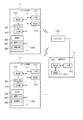
図1は、表示システム1の構成及び設置状態を示す図である。
表示システム1は、プロジェクター100(表示装置)に、タブレット2及びタブレット3を無線通信回線によりデータ通信可能に接続し、書画カメラ4を有線接続した構成を有する。表示システム1を構成するタブレット2、3の数について制限はなく、本実施形態では、1台のタブレット2と、複数台のタブレット3とを接続する例を示す。
FIG. 1 is a diagram illustrating a configuration and an installation state of the display system 1.
The display system 1 has a configuration in which a tablet 2 and a tablet 3 are connected to a projector 100 (display device) via a wireless communication line so that data communication is possible, and a document camera 4 is connected by wire. There is no restriction | limiting about the number of the tablets 2 and 3 which comprise the display system 1, In this embodiment, the example which connects the one tablet 2 and the several tablet 3 is shown.

表示システム1は、タブレット2を操作するユーザーと、タブレット3を操作する複数のユーザーとが使用する。例えば教育の場において、教育を行う側のユーザー(例えば、先生)がタブレット2を使用し、教育を受ける側のユーザー(例えば、生徒)がタブレット3を使用する。タブレット2のユーザーは、指示体70を用いた操作、及び、書画カメラ4の操作も行う。   The display system 1 is used by a user who operates the tablet 2 and a plurality of users who operate the tablet 3. For example, in an educational setting, a user who gives education (for example, a teacher) uses the tablet 2, and a user who receives education (for example, students) uses the tablet 3. The user of the tablet 2 also performs an operation using the indicator 70 and an operation of the document camera 4.

図1にはプロジェクター100の設置状態を示す。
プロジェクター100は、スクリーンSC(操作面)の上方又は斜め上方に設置され、スクリーンSCに向けて画像を投射する。スクリーンSCは、壁面に固定され、又は床面に立設された平板又は幕である。本発明は、この例に限定されず、壁面をスクリーンSCとして使用することも可能である。この場合、スクリーンSCとして使用される壁面の上部にプロジェクター100を取り付けるとよい。
FIG. 1 shows the installation state of the projector 100.
The projector 100 is installed above or obliquely above the screen SC (operation surface), and projects an image toward the screen SC. The screen SC is a flat plate or curtain fixed to the wall surface or standing on the floor surface. The present invention is not limited to this example, and the wall surface can be used as the screen SC. In this case, the projector 100 may be attached to the upper part of the wall surface used as the screen SC.

プロジェクター100は、PC(パーソナルコンピューター)、ビデオ再生装置、DVD再生装置、Blu−ray(登録商標) Disc(ブルーレイディスク)再生装置等の画像供給装置に接続してもよい。この場合、プロジェクター100は、画像供給装置から供給されるアナログ画像信号又はデジタル画像データに基づいて、スクリーンSCに画像を投射する。また、プロジェクター100は、内蔵する記憶部60(図3)や外部接続される記憶媒体に記憶された画像データを読み出して、この画像データに基づきスクリーンSCに画像を表示してもよい。   The projector 100 may be connected to an image supply device such as a PC (personal computer), a video playback device, a DVD playback device, or a Blu-ray (registered trademark) Disc (Blu-ray Disc) playback device. In this case, the projector 100 projects an image on the screen SC based on an analog image signal or digital image data supplied from the image supply device. Further, the projector 100 may read out image data stored in the built-in storage unit 60 (FIG. 3) or an externally connected storage medium, and display an image on the screen SC based on the image data.

スクリーンSCにおいて、プロジェクター100が画像を投射する最大範囲を、投射可能領域(表示領域)110とする。図1の例ではスクリーンSCの全体が投射可能領域110である。投射可能領域110の大きさは、プロジェクター100のズーム機能等により調整でき、投射可能領域110はスクリーンSCより小さくてもよい。
プロジェクター100は、投射可能領域を複数の領域に分割して、各領域に、それぞれ独立して画像を投射できる。図1の例では投射可能領域110が4つの領域111、112、113、114に分割される。各領域を区分する領域境界115は、図1の状態では投射可能領域110の縦(鉛直)方向中央及び横(水平)方向中央に位置するが、領域境界115の位置は後述するように移動できる。
In the screen SC, a maximum range in which the projector 100 projects an image is a projectable area (display area) 110. In the example of FIG. 1, the entire screen SC is a projectable area 110. The size of the projectable area 110 can be adjusted by the zoom function or the like of the projector 100, and the projectable area 110 may be smaller than the screen SC.
The projector 100 can divide the projectable region into a plurality of regions and project an image independently on each region. In the example of FIG. 1, the projectable area 110 is divided into four areas 111, 112, 113, and 114. The region boundary 115 that divides each region is located at the center in the vertical (vertical) direction and the center in the horizontal (horizontal) direction of the projectable region 110 in the state of FIG. 1, but the position of the region boundary 115 can be moved as will be described later. .

本実施形態のプロジェクター100は、タブレット2、3が送信する画像データに基づく画像、書画カメラ4が送信する画像データに基づく画像、及び、指示体70の操作に応じてプロジェクター100が描画する画像等を、領域111、112、113、114に表示する。   The projector 100 according to the present embodiment includes an image based on image data transmitted from the tablets 2 and 3, an image based on image data transmitted from the document camera 4, an image drawn by the projector 100 in response to an operation of the indicator 70, and the like. Are displayed in regions 111, 112, 113, and 114.

プロジェクター100は、スクリーンSCに対するユーザーの操作を検出する機能を有する。ユーザーは、ペン型の指示体70の軸部72を手に持ち、指示体70の先端部71でスクリーンSCに対する操作を行う。この操作には、先端部71によりスクリーンSC上の位置を指定(指示)する操作、スクリーンSC上の異なる位置を連続して指示する操作等が含まれる。スクリーンSC上の位置を指示する操作は、指示体70の先端部71をスクリーンSCに一定時間接触させる操作であり、スクリーンSC上の異なる位置を連続して指示する操作とは、先端部71をスクリーンSCに接触させながら動かす操作である。   The projector 100 has a function of detecting a user operation on the screen SC. The user holds the shaft portion 72 of the pen-type indicator 70 in his / her hand and operates the screen SC with the tip portion 71 of the indicator 70. This operation includes an operation of designating (instructing) a position on the screen SC by the tip portion 71, an operation of sequentially instructing different positions on the screen SC, and the like. The operation for instructing the position on the screen SC is an operation for bringing the tip end portion 71 of the indicator 70 into contact with the screen SC for a certain period of time. This is an operation of moving while making contact with the screen SC.

プロジェクター100は、ユーザーが指示体70で行う操作を検出して、検出した操作をスクリーンSCの表示画像に反映させる。例えば、プロジェクター100は、先端部71が指示する操作位置の座標に基づき、プロジェクター100の機能を実行するGUI(Graphical User Interface)操作を実現する。また、プロジェクター100は、先端部71の操作位置の軌跡に沿って文字や図形を生成し、生成した文字や図形を投射可能領域110に投射する、描画機能を有する。   The projector 100 detects an operation performed by the user with the indicator 70, and reflects the detected operation on the display image of the screen SC. For example, the projector 100 realizes a GUI (Graphical User Interface) operation for executing the function of the projector 100 based on the coordinates of the operation position indicated by the distal end portion 71. In addition, the projector 100 has a drawing function of generating characters and figures along the locus of the operation position of the tip 71 and projecting the generated characters and figures onto the projectable area 110.

タブレット2は、平板状の本体に、タッチ操作が可能なタッチパネル201を有する。タブレット3も同様に、平板状の本体に、タッチ操作が可能なタッチパネル301を有する。タッチパネル201、301は表示画面としての液晶表示パネルや有機ELパネル等の表示パネルに、接触操作を検出するタッチパネルを重畳した構成である。   The tablet 2 has a touch panel 201 capable of touch operation on a flat body. Similarly, the tablet 3 has a touch panel 301 capable of a touch operation on a flat main body. The touch panels 201 and 301 have a configuration in which a touch panel for detecting a contact operation is superimposed on a display panel such as a liquid crystal display panel or an organic EL panel as a display screen.

書画カメラ4は、カメラヘッド402、及び、カメラヘッド402を支持する支柱403を有する。カメラヘッド402は下方を撮影する撮影部410(図2)を備え、カメラヘッド402の下方に設置される載置面401に載せられる被写体を撮影し、撮影画像データをプロジェクター100に送信する。   The document camera 4 includes a camera head 402 and a column 403 that supports the camera head 402. The camera head 402 includes a photographing unit 410 (FIG. 2) that photographs the lower part, photographs a subject placed on the mounting surface 401 installed below the camera head 402, and transmits photographed image data to the projector 100.

図2は、タブレット2、3及び書画カメラ4の機能ブロック図である。
タブレット2は、プロジェクター100に接続されるインターフェース部211を備える。インターフェース部211は、外部の機器に有線接続する有線接続用のコネクターを備え、このコネクターに対応するインターフェース回路を備えていてもよい。また、インターフェース部211は、無線通信インターフェースを備えていてもよい。有線接続用のコネクター及びインターフェース回路としては有線LAN、IEEE1394、USB、MHL(Mobile High-definition Link)(登録商標)、HDMI(登録商標)(High-Definition Multimedia Interface)等に準拠したものが挙げられる。また、無線通信インターフェースとしては無線LAN(WiFi(登録商標))、Bluetooth(登録商標)、Miracast(登録商標)等に準拠したものが挙げられる。本実施形態では、無線LAN通信可能な無線通信インターフェースを備える構成である。
FIG. 2 is a functional block diagram of the tablets 2 and 3 and the document camera 4.
The tablet 2 includes an interface unit 211 connected to the projector 100. The interface unit 211 may include a connector for wired connection for wired connection to an external device, and may include an interface circuit corresponding to this connector. The interface unit 211 may include a wireless communication interface. Examples of the connector and interface circuit for wired connection include those compliant with wired LAN, IEEE 1394, USB, MHL (Mobile High-definition Link) (registered trademark), HDMI (registered trademark) (High-Definition Multimedia Interface), and the like. . Examples of the wireless communication interface include those that comply with wireless LAN (WiFi (registered trademark)), Bluetooth (registered trademark), Miracast (registered trademark), and the like. In the present embodiment, a wireless communication interface capable of wireless LAN communication is provided.

タブレット2は、制御部212、表示部213、入力部214、及び記憶部220を備え、これらの各部及びインターフェース部211はバス230によりデータ通信可能に接続する。制御部212は、図示しないCPU、RAM、ROM等を備え、ROMが記憶する制御プログラム、及び記憶部220が記憶する制御プログラムを実行して、タブレット2の各部を制御する。   The tablet 2 includes a control unit 212, a display unit 213, an input unit 214, and a storage unit 220, and these units and the interface unit 211 are connected via a bus 230 so that data communication is possible. The control unit 212 includes a CPU, a RAM, a ROM, and the like (not shown), and controls each unit of the tablet 2 by executing a control program stored in the ROM and a control program stored in the storage unit 220.

表示部213及び入力部214はタッチパネル201に接続する。表示部213は、制御部212の制御に従い、タッチパネル201に各種画面を表示する。入力部214は、タッチパネル201における接触操作を検出して、検出した操作の位置を示す座標データを制御部212に出力する。   The display unit 213 and the input unit 214 are connected to the touch panel 201. The display unit 213 displays various screens on the touch panel 201 under the control of the control unit 212. The input unit 214 detects a touch operation on the touch panel 201 and outputs coordinate data indicating the position of the detected operation to the control unit 212.

記憶部220は、制御部212が実行するプログラムや、各種データを不揮発的に記憶する。記憶部220は、画像データ221及び接続情報222を記憶する。画像データ221は、タッチパネル201に表示する画像や文字等を含む表示用の画像データであり、制御部212は、画像データ221に基づく画像を表示部213に表示させることができる。また、制御部212は、画像データ221をインターフェース部211によりプロジェクター100に送信できる。   The storage unit 220 stores programs executed by the control unit 212 and various data in a nonvolatile manner. The storage unit 220 stores image data 221 and connection information 222. The image data 221 is display image data including images and characters displayed on the touch panel 201, and the control unit 212 can cause the display unit 213 to display an image based on the image data 221. Further, the control unit 212 can transmit the image data 221 to the projector 100 through the interface unit 211.

接続情報222は、インターフェース部211が無線通信によりプロジェクター100に接続するための情報を含む。例えば、タブレット2のMAC(Media Access Control)アドレス、IP(Internet Protocol)アドレス、ネットワーク名、SSID(Service Set Identifier)等を含む。また、接続情報222は、インターフェース部211が接続する機器のSSID、セキュリティ設定の種別、パスワードやパスキー、端末名称等を含んでもよい。セキュリティ設定は、例えば、WEP(Wired Equivalent Privacy)、WPA(Wi-Fi Protected Access)等から選択できる。
接続情報222は、タブレット2に接続するプロジェクター100等の外部機器に関する上記項目の情報と、インターフェース部211に関する上記項目の情報とを含んでもよい。
The connection information 222 includes information for the interface unit 211 to connect to the projector 100 by wireless communication. For example, it includes the MAC (Media Access Control) address, IP (Internet Protocol) address, network name, SSID (Service Set Identifier), etc. of the tablet 2. The connection information 222 may include an SSID of a device to which the interface unit 211 is connected, a type of security setting, a password, a passkey, a terminal name, and the like. The security setting can be selected from, for example, WEP (Wired Equivalent Privacy), WPA (Wi-Fi Protected Access), and the like.
The connection information 222 may include information on the above items related to external devices such as the projector 100 connected to the tablet 2 and information on the above items related to the interface unit 211.

制御部212は、接続情報222を参照して、プロジェクター100との間で無線通信を確立して、プロジェクター100と無線によるデータ通信を実行する。制御部212が画像データ221をプロジェクター100に送信すると、プロジェクター100が、画像データ221を受信して画像データ221に基づく画像を投射する。制御部212は、プロジェクター100に送信する画像データ221に基づく画像を、表示部213により表示することもできる。   The control unit 212 refers to the connection information 222, establishes wireless communication with the projector 100, and executes wireless data communication with the projector 100. When the control unit 212 transmits the image data 221 to the projector 100, the projector 100 receives the image data 221 and projects an image based on the image data 221. The control unit 212 can also cause the display unit 213 to display an image based on the image data 221 transmitted to the projector 100.

タブレット3は、タブレット2と同様に構成される。即ち、タブレット3は、プロジェクター100等の外部機器に接続するインターフェース部311を備える。インターフェース部311の構成は、インターフェース部211と同様である。
また、タブレット3は、制御部312、表示部313、入力部314、及び記憶部320を備え、これらの各部及びインターフェース部311はバス330によりデータ通信可能に接続する。制御部312は、図示しないCPU、RAM、ROM等を備え、ROMが記憶する制御プログラム、及び記憶部320が記憶する制御プログラムを実行して、タブレット3の各部を制御する。
The tablet 3 is configured similarly to the tablet 2. That is, the tablet 3 includes an interface unit 311 that is connected to an external device such as the projector 100. The configuration of the interface unit 311 is the same as that of the interface unit 211.
The tablet 3 includes a control unit 312, a display unit 313, an input unit 314, and a storage unit 320. These units and the interface unit 311 are connected to each other via a bus 330 so that data communication is possible. The control unit 312 includes a CPU, RAM, ROM, and the like (not shown), and controls each unit of the tablet 3 by executing a control program stored in the ROM and a control program stored in the storage unit 320.

表示部313及び入力部314はタッチパネル301に接続する。表示部313は、制御部312の制御に従い、タッチパネル301に各種画面を表示する。入力部314は、タッチパネル301における接触操作を検出して、検出した操作の位置を示す座標データを制御部312に出力する。   The display unit 313 and the input unit 314 are connected to the touch panel 301. The display unit 313 displays various screens on the touch panel 301 under the control of the control unit 312. Input unit 314 detects a touch operation on touch panel 301 and outputs coordinate data indicating the position of the detected operation to control unit 312.

記憶部320は、制御部312が実行するプログラムや、各種データを不揮発的に記憶する。記憶部320は、画像データ321及び接続情報322を記憶する。画像データ321は、タッチパネル301に表示する画像や文字等を含む表示用の画像データであり、制御部312は、画像データ321に基づく画像を表示部313に表示させることができる。また、制御部312は、画像データ321をインターフェース部311によりプロジェクター100に送信できる。   The storage unit 320 stores a program executed by the control unit 312 and various data in a nonvolatile manner. The storage unit 320 stores image data 321 and connection information 322. The image data 321 is display image data including images and characters displayed on the touch panel 301, and the control unit 312 can cause the display unit 313 to display an image based on the image data 321. Further, the control unit 312 can transmit the image data 321 to the projector 100 via the interface unit 311.

接続情報322は、インターフェース部311が無線通信によりプロジェクター100に接続するための情報を含む。例えば、タブレット3のMACアドレス、IPアドレス、ネットワーク名、SSID等を含む。また、接続情報322は、インターフェース部311が接続する機器のセキュリティ設定の種別、SSID、パスワードやパスキー、端末名称等を含んでもよい。接続情報322は、タブレット3に接続するプロジェクター100等の外部機器に関する上記項目の情報と、インターフェース部311に関する上記項目の情報とを含んでもよい。   The connection information 322 includes information for the interface unit 311 to connect to the projector 100 by wireless communication. For example, the MAC address, IP address, network name, SSID, and the like of the tablet 3 are included. Further, the connection information 322 may include the type of security setting of the device to which the interface unit 311 is connected, the SSID, the password or passkey, the terminal name, and the like. The connection information 322 may include information on the above items regarding external devices such as the projector 100 connected to the tablet 3 and information on the above items regarding the interface unit 311.

制御部312は、接続情報322を参照して、プロジェクター100との間で無線通信を確立して、プロジェクター100と無線によるデータ通信を実行する。制御部312が画像データ321をプロジェクター100に送信すると、プロジェクター100が、画像データ321を受信して画像データ321に基づく画像を投射する。制御部312は、プロジェクター100に送信する画像データ321に基づく画像を、表示部313により表示することもできる。   The control unit 312 refers to the connection information 322, establishes wireless communication with the projector 100, and executes wireless data communication with the projector 100. When the control unit 312 transmits the image data 321 to the projector 100, the projector 100 receives the image data 321 and projects an image based on the image data 321. The control unit 312 can also display an image based on the image data 321 transmitted to the projector 100 by the display unit 313.

書画カメラ4は、撮影部410と、撮影部410を制御する制御部411と、プロジェクター100に接続するインターフェース部412とを備える。本実施形態では、インターフェース部412は、プロジェクター100に対しUSB接続するUSBコネクター、及び、USBデバイスコントローラーを含む回路を有する。インターフェース部412は、表示用のアナログ画像信号を出力するインターフェース(例えば、D−Sub)であってもよいし、デジタルビデオデータを出力するインターフェース(例えば、DVI)であってもよい。インターフェース部412は、プロジェクター100に接続してデータを送信できればよく、例えば無線通信によりプロジェクター100に接続可能な構成であってもよい。   The document camera 4 includes a photographing unit 410, a control unit 411 that controls the photographing unit 410, and an interface unit 412 that is connected to the projector 100. In the present embodiment, the interface unit 412 has a circuit including a USB connector for USB connection to the projector 100 and a USB device controller. The interface unit 412 may be an interface (for example, D-Sub) that outputs an analog image signal for display, or may be an interface (for example, DVI) that outputs digital video data. The interface unit 412 only needs to be connected to the projector 100 and transmit data. For example, the interface unit 412 may be configured to be connectable to the projector 100 by wireless communication.

撮影部410はデジタルスチルカメラまたはデジタルビデオカメラであり、載置面401(図1)を撮影範囲に含むよう設置される。制御部411は撮影部410に撮影を実行させて撮影画像データを生成し、インターフェース部412から撮影画像データをプロジェクター100に送信する。制御部411は、撮影部410の撮影画像データをアナログ画像信号に変換してもよいし、デジタルビデオデータに変換してもよい。また、撮影部410はズーム及びフォーカス調整が可能な構成であってもよく、この場合、制御部411がズーム及びフォーカスの調整を制御する。
また、書画カメラ4は、撮影部410の撮影範囲すなわち載置面401を照明する照明装置を備えてもよく、この場合、制御部411は照明装置の点灯、消灯を制御する。
The photographing unit 410 is a digital still camera or a digital video camera, and is installed so as to include the placement surface 401 (FIG. 1) in the photographing range. The control unit 411 causes the photographing unit 410 to perform photographing, generates photographed image data, and transmits the photographed image data to the projector 100 from the interface unit 412. The control unit 411 may convert the captured image data of the imaging unit 410 into an analog image signal or digital video data. Further, the photographing unit 410 may be configured to be able to perform zoom and focus adjustment. In this case, the control unit 411 controls zoom and focus adjustment.
In addition, the document camera 4 may include an illumination device that illuminates the imaging range of the imaging unit 410, that is, the placement surface 401. In this case, the control unit 411 controls lighting and extinguishing of the illumination device.

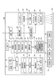
図3は、プロジェクター100及び指示体70の機能ブロック図である。
プロジェクター100は、外部機器に接続されるインターフェースとして、インターフェース(I/F)部11及び画像インターフェース(I/F)部12を備える。インターフェース部11及び画像インターフェース部12は、有線接続用のコネクターを備え、このコネクターに対応するインターフェース回路を備えてもよい。また、インターフェース部11及び画像インターフェース部12は、無線通信インターフェースを備えていてもよい。有線接続用のコネクター及びインターフェース回路としては有線LAN、IEEE1394、USB等に準拠したものが挙げられる。また、無線通信インターフェースとしては無線LANやBluetooth等に準拠したものが挙げられる。画像インターフェース部12には、HDMI等の画像データ用のインターフェースを用いることができ、D−Sub等のアナログ画像信号が入力されるインターフェースを用いてもよい。画像インターフェース部12は、音声データが入力されるインターフェースを備えてもよい。
FIG. 3 is a functional block diagram of the projector 100 and the indicator 70.
The projector 100 includes an interface (I / F) unit 11 and an image interface (I / F) unit 12 as interfaces connected to external devices. The interface unit 11 and the image interface unit 12 may include a connector for wired connection, and may include an interface circuit corresponding to the connector. The interface unit 11 and the image interface unit 12 may include a wireless communication interface. Examples of the connector and interface circuit for wired connection include those compliant with wired LAN, IEEE 1394, USB, and the like. Further, examples of the wireless communication interface include those compliant with wireless LAN, Bluetooth, and the like. As the image interface unit 12, an interface for image data such as HDMI can be used, and an interface to which an analog image signal such as D-Sub is input may be used. The image interface unit 12 may include an interface through which audio data is input.

インターフェース部11は、PC等の外部の装置との間で各種データを送受信するインターフェースである。インターフェース部11は、画像の投射に関するデータ、プロジェクター100の動作を設定するデータ等を入出力する。後述する制御部30は、インターフェース部11を介して外部の装置とデータを送受信する機能を有する。
画像インターフェース部12は、デジタル画像データが入力されるインターフェースである。本実施形態のプロジェクター100は、画像インターフェース部12を介して入力されるデジタル画像データに基づき画像を投射する。なお、プロジェクター100は、アナログ画像信号に基づき画像を投射する機能を備えていてもよく、この場合、画像インターフェース部12は、アナログ画像用のインターフェースと、アナログ画像信号をデジタル画像データに変換するA/D変換回路とを備えてもよい。
The interface unit 11 is an interface that transmits and receives various data to and from an external device such as a PC. The interface unit 11 inputs and outputs data relating to image projection, data for setting the operation of the projector 100, and the like. The control unit 30 described later has a function of transmitting / receiving data to / from an external device via the interface unit 11.
The image interface unit 12 is an interface through which digital image data is input. The projector 100 according to this embodiment projects an image based on digital image data input via the image interface unit 12. The projector 100 may have a function of projecting an image based on an analog image signal. In this case, the image interface unit 12 includes an analog image interface and an A for converting the analog image signal into digital image data. A / D conversion circuit may be provided.

インターフェース部11には、例えばタブレット2、3を接続でき、書画カメラ4は画像インターフェース部12及び画像インターフェース部12のいずれに接続してもよいが、本実施形態では、インターフェース部11にタブレット2、3及び書画カメラ4が接続する。
タブレット2、3はインターフェース部11の無線LANインターフェースに接続し、書画カメラ4はUSBインターフェースに接続する。
プロジェクター100は、インターフェース部11及び画像インターフェース部12に接続する機器のうち、画像データ又はアナログ画像信号を入力する機器を、画像ソースとして認識する。
For example, tablets 2 and 3 can be connected to the interface unit 11, and the document camera 4 may be connected to either the image interface unit 12 or the image interface unit 12, but in this embodiment, the tablet unit 2 is connected to the interface unit 11. 3 and the document camera 4 are connected.
The tablets 2 and 3 are connected to the wireless LAN interface of the interface unit 11, and the document camera 4 is connected to the USB interface.
The projector 100 recognizes, as an image source, a device that inputs image data or an analog image signal among devices connected to the interface unit 11 and the image interface unit 12.

プロジェクター100は、光学的な画像の形成を行う投射部20を備える。投射部20は、光源部21、光変調装置22及び投射光学系23を有する。光源部21は、キセノンランプ、超高圧水銀ランプ、LED(Light Emitting Diode)又はレーザー光源等からなる光源を備える。また、光源部21は、光源が発した光を光変調装置22に導くリフレクター及び補助リフレクターを備えていてもよい。さらに、光源部21は、投射光の光学特性を高めるためのレンズ群(図示略)、偏光板、又は光源が発した光の光量を光変調装置22に至る経路上で低減させる調光素子等を備えていてもよい。   The projector 100 includes a projection unit 20 that forms an optical image. The projection unit 20 includes a light source unit 21, a light modulation device 22, and a projection optical system 23. The light source unit 21 includes a light source including a xenon lamp, an ultra-high pressure mercury lamp, an LED (Light Emitting Diode), a laser light source, or the like. The light source unit 21 may include a reflector and an auxiliary reflector that guide light emitted from the light source to the light modulation device 22. Further, the light source unit 21 is a lens group (not shown) for enhancing the optical characteristics of the projection light, a polarizing plate, a light control element that reduces the amount of light emitted from the light source on the path to the light modulation device 22, and the like. May be provided.

光変調装置22は、例えばRGBの三原色に対応した3枚の透過型液晶パネルを備え、この液晶パネルを透過する光を変調して画像光を生成する。光源部21からの光はRGBの3色の色光に分離され、各色光は対応する各液晶パネルに入射される。各液晶パネルを通過して変調された色光はクロスダイクロイックプリズム等の合成光学系によって合成され、投射光学系23に射出される。   The light modulation device 22 includes, for example, three transmissive liquid crystal panels corresponding to the three primary colors of RGB, and generates image light by modulating light transmitted through the liquid crystal panel. The light from the light source unit 21 is separated into three color lights of RGB, and each color light is incident on the corresponding liquid crystal panel. The color light modulated by passing through each liquid crystal panel is combined by a combining optical system such as a cross dichroic prism and emitted to the projection optical system 23.

投射光学系23は、光変調装置22により変調された画像光をスクリーンSC方向へ導き、スクリーンSC上に結像させるレンズ群を備える。また、投射光学系23は、スクリーンSCの表示画像の拡大・縮小を行うズーム機構、フォーカスの調整を行うフォーカス調整機構を備えていてもよい。プロジェクター100が短焦点型である場合、投射光学系23に、画像光をスクリーンSCに向けて反射する凹面鏡を備えていてもよい。   The projection optical system 23 includes a lens group that guides the image light modulated by the light modulation device 22 toward the screen SC and forms an image on the screen SC. Further, the projection optical system 23 may include a zoom mechanism for enlarging / reducing the display image on the screen SC and a focus adjusting mechanism for adjusting the focus. When the projector 100 is a short focus type, the projection optical system 23 may be provided with a concave mirror that reflects image light toward the screen SC.

投射部20は、制御部30の制御に従って光源部21を点灯させる光源駆動部45、及び制御部30の制御に従って光変調装置22を動作させる光変調装置駆動部46に接続される。光源駆動部45は、光源部21の点灯、消灯の切り替えを行い、光源部21の光量を調整する機能を有していてもよい。   The projection unit 20 is connected to a light source driving unit 45 that turns on the light source unit 21 according to the control of the control unit 30 and a light modulation device driving unit 46 that operates the light modulation device 22 according to the control of the control unit 30. The light source drive unit 45 may have a function of adjusting the light amount of the light source unit 21 by switching the light source unit 21 on and off.

プロジェクター100は、投射部20が投射する画像を処理する画像処理系を備える。この画像処理系は、プロジェクター100を制御する制御部30、記憶部60、入力受付部17、画像処理部40、光源駆動部45及び光変調装置駆動部46を含む。また、画像処理部40にはフレームメモリー41が接続され、制御部30には操作検出部50が接続される。これらの各部を画像処理系に含めてもよい。   The projector 100 includes an image processing system that processes an image projected by the projection unit 20. The image processing system includes a control unit 30 that controls the projector 100, a storage unit 60, an input receiving unit 17, an image processing unit 40, a light source driving unit 45, and a light modulation device driving unit 46. Further, a frame memory 41 is connected to the image processing unit 40, and an operation detection unit 50 is connected to the control unit 30. These units may be included in the image processing system.

制御部30は、所定の制御プログラム61を実行することによりプロジェクター100の各部を制御する。記憶部60は、制御部30が実行する制御プログラム61を記憶する。また、記憶部60は、外部機器情報62、及び表示位置情報63を不揮発的に記憶する。外部機器情報62は、インターフェース部11及び画像インターフェース部12に接続する外部機器に関する情報を含み、外部機器を特定する情報を含んでもよい。例えば、インターフェース部11にタブレット2、3が接続される場合、外部機器情報62は、タブレット2との通信を実行するための各種情報、及び、タブレット2を特定する情報を含む。具体的には、タブレット2のMACアドレス、IPアドレス、ネットワーク名、SSID、タブレット2との無線通信のセキュリティ設定の種別、SSID、パスワードやパスキー、端末名称等を含んでもよい。外部機器情報62は、タブレット3についても同様の情報を含み、記憶部60は、タブレット2に関する外部機器情報62とタブレット3に関する外部機器情報62とが別の情報として記憶してもよい。また、外部機器情報62は、タブレット2とタブレット3とを識別可能な情報を含む。本実施形態では複数のタブレット3がプロジェクター100に接続するので、外部機器情報62は、それぞれのタブレット3を識別する情報を含んでもよい。また、それぞれのタブレット3に対応する外部機器情報62が、独立した情報として記憶部60に記憶されてもよい。また、外部機器情報62は、インターフェース部11に接続される書画カメラ4(図1)に関する情報を含む。   The control unit 30 controls each unit of the projector 100 by executing a predetermined control program 61. The storage unit 60 stores a control program 61 executed by the control unit 30. In addition, the storage unit 60 stores external device information 62 and display position information 63 in a nonvolatile manner. The external device information 62 includes information regarding external devices connected to the interface unit 11 and the image interface unit 12, and may include information for specifying the external device. For example, when the tablets 2 and 3 are connected to the interface unit 11, the external device information 62 includes various information for executing communication with the tablet 2 and information for specifying the tablet 2. Specifically, the MAC address, IP address, network name, SSID, security communication type of the tablet 2, SSID, password, passkey, terminal name, and the like may be included. The external device information 62 includes the same information for the tablet 3, and the storage device 60 may store the external device information 62 related to the tablet 2 and the external device information 62 related to the tablet 3 as different information. The external device information 62 includes information that can identify the tablet 2 and the tablet 3. In the present embodiment, since a plurality of tablets 3 are connected to the projector 100, the external device information 62 may include information for identifying each tablet 3. Further, the external device information 62 corresponding to each tablet 3 may be stored in the storage unit 60 as independent information. The external device information 62 includes information related to the document camera 4 (FIG. 1) connected to the interface unit 11.

表示位置情報63は、投射可能領域110に設けられる領域111、112、113、114の各領域と、インターフェース部11及び画像インターフェース部12に接続する機器との対応を定める情報である。プロジェクター100は、領域111、112、113、114のそれぞれに、プロジェクター100に接続される機器を対応付けることが可能である。詳細は後述するが、本実施形態では、領域111にタブレット2が対応付けられ、領域112に書画カメラ4が、領域114にタブレット3が対応付けられる。表示位置情報63は、例えば上記の対応関係を示す情報を含む。   The display position information 63 is information that defines the correspondence between the areas 111, 112, 113, and 114 provided in the projectable area 110 and devices connected to the interface unit 11 and the image interface unit 12. The projector 100 can associate a device connected to the projector 100 with each of the regions 111, 112, 113, and 114. Although details will be described later, in this embodiment, the tablet 2 is associated with the area 111, the document camera 4 is associated with the area 112, and the tablet 3 is associated with the area 114. The display position information 63 includes information indicating the correspondence relationship, for example.

画像処理部40は、制御部30の制御に従って、インターフェース部11または画像インターフェース部12を介して入力される画像データを処理し、光変調装置駆動部46に画像信号を出力する。画像処理部40が実行する処理は、3D(立体)画像と2D(平面)画像の判別処理、解像度変換処理、フレームレート変換処理、歪み補正処理、デジタルズーム処理、色調補正処理、輝度補正処理等である。画像処理部40は、制御部30により指定された処理を実行し、必要に応じて、制御部30から入力されるパラメーターを使用して処理を行う。また、上記のうち複数の処理を組み合わせて実行することも勿論可能である。
画像処理部40は、フレームメモリー41に接続される。画像処理部40は、インターフェース部11または画像インターフェース部12から入力される画像データをフレームメモリー41に展開して、展開した画像データに対し上記の各種処理を実行する。画像処理部40は、処理後の画像データをフレームメモリー41から読み出して、この画像データに対応するR、G、Bの画像信号を生成し、光変調装置駆動部46に出力する。
光変調装置駆動部46は、光変調装置22の液晶パネルに接続される。光変調装置駆動部46は、画像処理部40から入力される画像信号に基づいて液晶パネルを駆動し、各液晶パネルに画像を描画する。
The image processing unit 40 processes image data input via the interface unit 11 or the image interface unit 12 under the control of the control unit 30, and outputs an image signal to the light modulation device driving unit 46. The processing executed by the image processing unit 40 includes 3D (stereoscopic) image and 2D (planar) image discrimination processing, resolution conversion processing, frame rate conversion processing, distortion correction processing, digital zoom processing, color tone correction processing, luminance correction processing, and the like. is there. The image processing unit 40 executes processing designated by the control unit 30 and performs processing using parameters input from the control unit 30 as necessary. Of course, it is also possible to execute a combination of a plurality of processes.
The image processing unit 40 is connected to the frame memory 41. The image processing unit 40 develops the image data input from the interface unit 11 or the image interface unit 12 in the frame memory 41, and executes the various processes described above on the developed image data. The image processing unit 40 reads out the processed image data from the frame memory 41, generates R, G, and B image signals corresponding to the image data, and outputs them to the light modulation device driving unit 46.
The light modulation device driving unit 46 is connected to the liquid crystal panel of the light modulation device 22. The light modulator driving unit 46 drives the liquid crystal panel based on the image signal input from the image processing unit 40 and draws an image on each liquid crystal panel.

入力受付部17は、入力デバイスとして機能するリモコン受光部18及び操作パネル19に接続され、リモコン受光部18及び操作パネル19を介した操作を検出する。
リモコン受光部18は、プロジェクター100のユーザーが使用するリモコン(図示略)がボタン操作に対応して送信した赤外線信号を受光する。リモコン受光部18は、上記リモコンから受光した赤外線信号をデコードして、上記リモコンにおける操作内容を示す操作データを生成し、制御部30に出力する。
操作パネル19は、プロジェクター100の外装筐体に設けられ、各種スイッチ及びインジケーターランプを有する。入力受付部17は、制御部30の制御に従い、プロジェクター100の動作状態や設定状態に応じて操作パネル19のインジケーターランプを適宜点灯及び消灯させる。操作パネル19のスイッチが操作されると、操作されたスイッチに対応する操作データが入力受付部17から制御部30に出力される。
The input receiving unit 17 is connected to a remote control light receiving unit 18 and an operation panel 19 that function as an input device, and detects an operation via the remote control light receiving unit 18 and the operation panel 19.
The remote control light receiving unit 18 receives an infrared signal transmitted in response to a button operation by a remote control (not shown) used by the user of the projector 100. The remote control light receiving unit 18 decodes the infrared signal received from the remote control, generates operation data indicating the operation content of the remote control, and outputs the operation data to the control unit 30.
The operation panel 19 is provided in the exterior casing of the projector 100 and includes various switches and indicator lamps. The input receiving unit 17 appropriately turns on and off the indicator lamp of the operation panel 19 according to the operation state and setting state of the projector 100 according to the control of the control unit 30. When a switch on the operation panel 19 is operated, operation data corresponding to the operated switch is output from the input receiving unit 17 to the control unit 30.

操作検出部50は、指示体70による操作位置を検出する。操作検出部50は、撮影部51、送信部52、撮影制御部53、対象検出部54及び座標算出部55の各部を備える。   The operation detection unit 50 detects an operation position by the indicator 70. The operation detection unit 50 includes an imaging unit 51, a transmission unit 52, an imaging control unit 53, an object detection unit 54, and a coordinate calculation unit 55.

撮影部51は、少なくとも投射可能領域110を含む撮影範囲を撮影し、撮影画像を形成する。撮影部51は、赤外光を撮影する赤外用撮像素子、及び、インターフェース回路を備え、赤外光による撮影を行う。撮像素子には、CCD、CMOSのいずれを用いることも可能であり、また、他の素子を用いることもできる。撮影部51の撮影方向および撮影範囲(画角)は、投射光学系23と同じ方向、又は略同じ方向を向き、投射光学系23がスクリーンSC上に画像を投射する範囲をカバーする。撮影部51は撮影画像データを出力する。   The imaging unit 51 captures an imaging range including at least the projectable area 110 and forms a captured image. The imaging unit 51 includes an infrared imaging element that captures infrared light and an interface circuit, and performs imaging using infrared light. Either an CCD or a CMOS can be used as the image pickup element, and other elements can also be used. The shooting direction and shooting range (angle of view) of the shooting unit 51 are directed in the same direction or substantially the same direction as the projection optical system 23, and cover the range in which the projection optical system 23 projects an image on the screen SC. The photographing unit 51 outputs photographed image data.

撮影制御部53は、制御部30の制御に従って撮影部51を制御し、撮影部51に撮影を実行させる。撮影制御部53は、撮影部51の撮影画像データを取得して、対象検出部54に出力する。撮影部51が赤外光を撮影した撮影画像データには、指示体70が発する赤外光の像が写る。   The imaging control unit 53 controls the imaging unit 51 according to the control of the control unit 30 and causes the imaging unit 51 to execute imaging. The imaging control unit 53 acquires the captured image data of the imaging unit 51 and outputs it to the target detection unit 54. An image of the infrared light emitted from the indicator 70 appears in the captured image data obtained by capturing the infrared light by the imaging unit 51.

送信部52は、撮影制御部53の制御に従って、指示体70に対して同期用の赤外線信号を送信する。送信部52は、赤外LED等の光源を有し、この光源を撮影制御部53の制御に従って点灯及び消灯させる。   The transmission unit 52 transmits an infrared signal for synchronization to the indicator 70 according to the control of the imaging control unit 53. The transmission unit 52 has a light source such as an infrared LED, and turns on and off the light source according to the control of the imaging control unit 53.

対象検出部54は、撮影部51の撮影画像データに写った赤外光の像を検出して、撮影画像データにおける、指示体70の操作位置の座標を検出する。また、対象検出部54は、指示体70の先端部71がスクリーンSCに接触しているか否かを判定して、先端部71がスクリーンSCに接触しているか否かを示すタッチ情報を生成する。指示体70の先端部71がスクリーンSCに接触しているか否かの判定方法は後述する。   The object detection unit 54 detects the infrared light image captured in the captured image data of the imaging unit 51, and detects the coordinates of the operation position of the indicator 70 in the captured image data. Further, the target detection unit 54 determines whether or not the tip portion 71 of the indicator 70 is in contact with the screen SC, and generates touch information indicating whether or not the tip portion 71 is in contact with the screen SC. . A method for determining whether or not the tip 71 of the indicator 70 is in contact with the screen SC will be described later.

対象検出部54が検出する指示体70の操作位置の座標は、撮影部51の撮影画像データにおける座標である。
座標算出部55は、操作位置の座標を、スクリーンSCにおける操作位置の座標に変換する。本実施形態では、投射部20が投射する投射画像における座標に変換される。投射画像における座標は、プロジェクター100とスクリーンSCとの距離、投射光学系23におけるズーム率、プロジェクター100の設置角度、撮影部51とスクリーンSCとの距離等の様々な要素の影響を受ける。座標算出部55は、事前に実施されるキャリブレーションの結果に基づき、撮影画像データにおける操作位置の座標から、スクリーンSCの表示画像における操作位置の座標を算出する。キャリブレーションでは、所定のパターン画像を投射部20からスクリーンSCに投射して、表示されたパターン画像を撮影部51で撮影する。撮影部51の撮影したパターン画像に基づいて、撮影画像データにおける座標と、スクリーンSCの表示画像上の座標との対応関係(座標変換パラメーター)が導かれる。投射画像における操作位置の座標に基づき、制御部30は、フレームメモリー41に描画される投射画像に対する操作位置を特定できる。
The coordinates of the operation position of the indicator 70 detected by the target detection unit 54 are the coordinates in the captured image data of the imaging unit 51.
The coordinate calculation unit 55 converts the coordinates of the operation position into the coordinates of the operation position on the screen SC. In this embodiment, it is converted into coordinates in the projection image projected by the projection unit 20. The coordinates in the projected image are affected by various factors such as the distance between the projector 100 and the screen SC, the zoom ratio in the projection optical system 23, the installation angle of the projector 100, and the distance between the photographing unit 51 and the screen SC. The coordinate calculation unit 55 calculates the coordinates of the operation position in the display image of the screen SC from the coordinates of the operation position in the captured image data based on the result of calibration performed in advance. In the calibration, a predetermined pattern image is projected from the projection unit 20 onto the screen SC, and the displayed pattern image is photographed by the photographing unit 51. Based on the pattern image captured by the imaging unit 51, the correspondence (coordinate conversion parameter) between the coordinates in the captured image data and the coordinates on the display image of the screen SC is derived. Based on the coordinates of the operation position in the projection image, the control unit 30 can specify the operation position for the projection image drawn in the frame memory 41.

指示体70は、制御部73、送受信部74、操作スイッチ75及び電源部76を備え、これらの各部は軸部72(図1)に収容される。制御部73は、送受信部74及び操作スイッチ75に接続され、操作スイッチ75のオン/オフ状態を検出する。操作スイッチ75は、指示体70の先端部71に配置されており、先端部71がスクリーンSCに押し付けられた場合にオンとなる。送受信部74は、赤外LED等の光源と、赤外光を受光する受光素子とを備え、制御部73の制御に従って光源を点灯及び消灯させるとともに、受光素子の受光状態を示す信号を制御部73に出力する。
電源部76は、電源として乾電池又は二次電池を有し、制御部73、送受信部74及び操作スイッチ75の各部に電力を供給する。指示体70は、電源部76からの電源供給をオン/オフする電源スイッチを備えていてもよい。
The indicator 70 includes a control unit 73, a transmission / reception unit 74, an operation switch 75, and a power source unit 76. These units are accommodated in a shaft unit 72 (FIG. 1). The control unit 73 is connected to the transmission / reception unit 74 and the operation switch 75 and detects the on / off state of the operation switch 75. The operation switch 75 is disposed at the distal end portion 71 of the indicator 70 and is turned on when the distal end portion 71 is pressed against the screen SC. The transmission / reception unit 74 includes a light source such as an infrared LED and a light receiving element that receives infrared light. To 73.
The power supply unit 76 includes a dry battery or a secondary battery as a power supply, and supplies power to the control unit 73, the transmission / reception unit 74, and the operation switch 75. The indicator 70 may include a power switch that turns on / off the power supply from the power supply unit 76.

操作検出部50と指示体70との相互の通信により、撮影部51の撮影画像データから指示体70の操作位置を特定する方法について説明する。
プロジェクター100の制御部30は、指示体70による操作を検出する場合に、撮影制御部53を制御して、送信部52から同期用の信号を送信させる。すなわち、撮影制御部53は、制御部30の制御に従って、送信部52の光源を所定の周期で点灯させる。送信部52が周期的に発する赤外光が、操作検出部50と指示体70とを同期させる同期信号として機能する。
一方、指示体70の制御部73は、電源部76から電源の供給が開始され、所定の初期化動作を行った後、プロジェクター100の送信部52が発する赤外光を、送受信部74により受光する。送信部52が周期的に発する赤外光を送受信部74により受光すると、制御部73は、この赤外光のタイミングに同期させて、予め設定された指示体70に固有の点灯パターンで送受信部74の光源を点灯(発光)させる。また、制御部73は、操作スイッチ75の操作状態に応じて、送受信部74の点灯パターンを切り替える。このため、プロジェクター100の対象検出部54は、順次撮影される複数の撮影画像データに基づいて、指示体70の操作状態、すなわち先端部71がスクリーンSCに押しつけられているか否かを判定できる。
また、制御部73は、電源部76から電源が供給されている間、上記のパターンを繰り返し実行する。つまり、送信部52は、指示体70に対し、同期用の赤外線信号を周期的に送信し、指示体70は、送信部52が送信する赤外線信号に同期して、予め設定された赤外線信号を送信する。
A method for specifying the operation position of the indicator 70 from the captured image data of the imaging unit 51 by mutual communication between the operation detection unit 50 and the indicator 70 will be described.
When the control unit 30 of the projector 100 detects an operation by the indicator 70, the control unit 30 controls the photographing control unit 53 to transmit a synchronization signal from the transmission unit 52. That is, the imaging control unit 53 turns on the light source of the transmission unit 52 at a predetermined cycle in accordance with the control of the control unit 30. The infrared light periodically emitted from the transmission unit 52 functions as a synchronization signal that synchronizes the operation detection unit 50 and the indicator 70.
On the other hand, the control unit 73 of the indicator 70 receives the infrared light emitted from the transmission unit 52 of the projector 100 by the transmission / reception unit 74 after the supply of power from the power supply unit 76 is started and a predetermined initialization operation is performed. To do. When the infrared light emitted periodically by the transmission unit 52 is received by the transmission / reception unit 74, the control unit 73 synchronizes with the timing of this infrared light and transmits and receives the transmission / reception unit with a preset lighting pattern specific to the indicator 70. 74 light sources are turned on (emitted). Further, the control unit 73 switches the lighting pattern of the transmission / reception unit 74 according to the operation state of the operation switch 75. For this reason, the target detection unit 54 of the projector 100 can determine the operating state of the indicator 70, that is, whether or not the distal end portion 71 is pressed against the screen SC, based on a plurality of captured image data that are sequentially captured.
The control unit 73 repeatedly executes the above pattern while power is supplied from the power supply unit 76. That is, the transmission unit 52 periodically transmits an infrared signal for synchronization to the indicator 70, and the indicator 70 transmits a preset infrared signal in synchronization with the infrared signal transmitted by the transmission unit 52. Send.

撮影制御部53は、撮影部51による撮影タイミングを、指示体70が点灯するタイミングに合わせる制御を行う。撮影タイミングは、撮影制御部53が送信部52を点灯させるタイミングに基づいて決定される。対象検出部54は、順次撮影される複数の撮影画像データのそれぞれに指示体70の光の像が写っているか否かにより、指示体70が点灯するパターンを特定できる。対象検出部54は、複数の撮影画像データに基づいて、指示体70の先端部71がスクリーンSCに押しつけられているか否かを判定して、タッチ情報を生成する。
また、指示体70の点灯パターンは、指示体70の個体毎に固有のパターン、又は複数の指示体70に共通のパターンと個体毎に固有のパターンとを含むものとすることができる。この場合、対象検出部54は、撮影画像データに複数の指示体70が発する赤外光の像が含まれる場合に、各々の像を、異なる指示体70の像として区別できる。
The shooting control unit 53 performs control to match the shooting timing of the shooting unit 51 with the timing when the indicator 70 is turned on. The shooting timing is determined based on the timing at which the shooting control unit 53 turns on the transmission unit 52. The object detection unit 54 can specify a pattern in which the indicator 70 is turned on depending on whether or not the light image of the indicator 70 is captured in each of a plurality of photographed image data that are sequentially photographed. The target detection unit 54 determines whether or not the distal end portion 71 of the indicator 70 is pressed against the screen SC based on the plurality of captured image data, and generates touch information.
Further, the lighting pattern of the indicator 70 may include a pattern unique to each individual indicator 70, or a pattern common to the plurality of indicators 70 and a pattern unique to each individual. In this case, the target detection unit 54 can distinguish each image as an image of a different indicator 70 when the captured image data includes images of infrared light emitted from the plurality of indicators 70.

制御部30は、記憶部60が記憶する制御プログラム61を読み出して実行することにより投射制御部31、操作取得部32、通信制御部33、描画部34、及び画像取得部35の機能を実現し、プロジェクター100の各部を制御する。   The control unit 30 reads and executes the control program 61 stored in the storage unit 60, thereby realizing the functions of the projection control unit 31, the operation acquisition unit 32, the communication control unit 33, the drawing unit 34, and the image acquisition unit 35. Control each unit of the projector 100.

投射制御部31は、入力受付部17から入力される操作データに基づいて、ユーザーがリモコンを操作して行った操作内容を取得する。投射制御部31は、ユーザーが行った操作に応じて画像処理部40、光源駆動部45及び光変調装置駆動部46を制御し、スクリーンSCに画像を投射させる。
また、投射制御部31は、画像処理部40を制御して、上述した3D(立体)画像と2D(平面)画像の判別処理、解像度変換処理、フレームレート変換処理、歪み補正処理、デジタルズーム処理、色調補正処理、輝度補正処理等を実行させる。また、投射制御部31は、画像処理部40の処理に合わせて光源駆動部45を制御し、光源部21の光量を制御する。
Based on the operation data input from the input receiving unit 17, the projection control unit 31 acquires the operation content performed by the user operating the remote control. The projection control unit 31 controls the image processing unit 40, the light source driving unit 45, and the light modulation device driving unit 46 according to an operation performed by the user, and projects an image on the screen SC.
Further, the projection control unit 31 controls the image processing unit 40 to determine the above-described 3D (stereoscopic) image and 2D (planar) image, resolution conversion processing, frame rate conversion processing, distortion correction processing, digital zoom processing, Color tone correction processing, luminance correction processing, and the like are executed. Further, the projection control unit 31 controls the light source driving unit 45 in accordance with the processing of the image processing unit 40 and controls the light amount of the light source unit 21.

操作取得部32は、操作検出部50が検出する指示体70の操作位置を取得する。また、操作取得部32は、投射可能領域110にメニューバー等のGUI操作用の画像が表示された状態で、操作検出部50が指示体70の操作位置を検出した場合、操作位置に対応する画像を特定し、指示内容を検出する。例えば、メニューバーが表示された状態で、指示体70の操作位置に対応するメニューバー中のアイコンを特定し、特定したアイコンの機能を検出する。   The operation acquisition unit 32 acquires the operation position of the indicator 70 detected by the operation detection unit 50. The operation acquisition unit 32 corresponds to the operation position when the operation detection unit 50 detects the operation position of the indicator 70 in a state where a GUI operation image such as a menu bar is displayed in the projectable area 110. The image is specified and the instruction content is detected. For example, in the state where the menu bar is displayed, an icon in the menu bar corresponding to the operation position of the indicator 70 is specified, and the function of the specified icon is detected.

通信制御部33は、インターフェース部11を介したタブレット2及びタブレット3との通信を制御する。通信制御部33は、複数のタブレット3から1または複数のタブレット3を選択し、選択したタブレット3に対し画像データを送信する等の制御を行う。   The communication control unit 33 controls communication with the tablet 2 and the tablet 3 via the interface unit 11. The communication control unit 33 performs control such as selecting one or a plurality of tablets 3 from a plurality of tablets 3 and transmitting image data to the selected tablets 3.

描画部34は、操作検出部50が検出する指示体70の操作位置に従って、文字や図形を描画する。描画部34は、操作取得部32が描画を指示する操作を検出した場合に、指示体70の操作位置の軌跡を取得し、この軌跡に基づいて直線、曲線、多角形等の図形(画像)を生成する。描画部34が生成する画像の種類は、操作取得部32が検出する操作により指定される。描画部34が生成する画像は画像処理部40に転送され、投射制御部31の制御に従って、画像処理部40がフレームメモリー41上の画像に描画画像を合成する。これにより、描画部34が描画する画像が投射部20により投射される。   The drawing unit 34 draws characters and figures in accordance with the operation position of the indicator 70 detected by the operation detection unit 50. When the operation acquisition unit 32 detects an operation instructing drawing, the drawing unit 34 acquires a locus of the operation position of the indicator 70, and a graphic (image) such as a straight line, a curve, or a polygon based on the locus. Is generated. The type of image generated by the drawing unit 34 is specified by an operation detected by the operation acquisition unit 32. The image generated by the drawing unit 34 is transferred to the image processing unit 40, and the image processing unit 40 combines the drawing image with the image on the frame memory 41 under the control of the projection control unit 31. Thereby, the image drawn by the drawing unit 34 is projected by the projection unit 20.

画像取得部35は、インターフェース部11及び画像インターフェース部12に接続する外部機器から入力される画像データを取得する。インターフェース部11または画像インターフェース部12からアナログ画像信号が入力された場合、画像取得部35は、このアナログ画像信号を変換したデジタル画像データを取得する。画像取得部35は、取得した画像データを、入力元の外部機器に対応付けて取得する。   The image acquisition unit 35 acquires image data input from an external device connected to the interface unit 11 and the image interface unit 12. When an analog image signal is input from the interface unit 11 or the image interface unit 12, the image acquisition unit 35 acquires digital image data obtained by converting the analog image signal. The image acquisition unit 35 acquires the acquired image data in association with the input external device.

投射制御部31は、画像取得部35が取得する画像データを、表示位置情報63に基づいて領域111、112、113、114のいずれかに対応付ける。投射制御部31は、画像取得部35が取得した画像データに基づく画像を画像処理部40に出力し、フレームメモリー41に描画させる。画像処理部40は、投射制御部31が入力する画像データに基づく画像を、フレームメモリー41内の対応する領域に描画する。フレームメモリー41には、領域111、112、113、114を含む投射可能領域110全体に対応する画像が形成される。   The projection control unit 31 associates the image data acquired by the image acquisition unit 35 with any of the regions 111, 112, 113, 114 based on the display position information 63. The projection control unit 31 outputs an image based on the image data acquired by the image acquisition unit 35 to the image processing unit 40 and causes the frame memory 41 to draw the image. The image processing unit 40 draws an image based on the image data input by the projection control unit 31 in a corresponding area in the frame memory 41. In the frame memory 41, an image corresponding to the entire projectable area 110 including the areas 111, 112, 113, and 114 is formed.

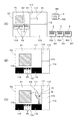
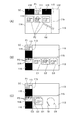
図4〜図7の各図は、表示システム1の表示例およびスクリーンSCに対する操作の例を示す図である。
以下の説明では、投射可能領域110の領域111がタブレット2に対応付けられ、領域112は書画カメラ4に対応付けられ、領域114がタブレット3に対応付けられる例を説明する。従って、領域111、112、114は、機器対応領域に相当する。この例で、領域113は画像を処理する処理領域である。また、領域114には複数のタブレット3が対応付けられ、領域114は複数機器対応領域に相当する。プロジェクター100では、いずれか1つのタブレット3を領域111、112、113、114のいずれかに対応付けることも可能であるが、以下の例では、複数のタブレット3の全てが領域114に対応付けられる。
4 to 7 are diagrams illustrating display examples of the display system 1 and examples of operations on the screen SC.
In the following description, an example in which the area 111 of the projectable area 110 is associated with the tablet 2, the area 112 is associated with the document camera 4, and the area 114 is associated with the tablet 3 will be described. Accordingly, the regions 111, 112, and 114 correspond to device-corresponding regions. In this example, the area 113 is a processing area for processing an image. In addition, a plurality of tablets 3 are associated with the region 114, and the region 114 corresponds to a region corresponding to a plurality of devices. In the projector 100, any one tablet 3 can be associated with any one of the regions 111, 112, 113, and 114. However, in the following example, all of the plurality of tablets 3 are associated with the region 114.

図4(A)は初期状態における表示例と操作の例を示し、図4(B)は(A)の操作に対応して表示が変化した例を示し、図4(C)は描画操作に対応して表示が変化した例を示す。図4(A)にはタブレット2、3をスクリーンSCとともに図示する。
図4(A)の表示例は、タブレット2及び複数のタブレット3と、プロジェクター100とが動作する場合の例である。タブレット2はタッチパネル201に表示画像P21を表示し、それぞれのタブレット3はタッチパネル301に描画画像P31を表示する。
タブレット2は、表示画像P21の画像データをプロジェクター100に送信し、各々のタブレット3は描画画像P31の画像データをプロジェクター100に送信する。プロジェクター100は、スクリーンSCの領域111に、表示画像P21と同じ表示画像P1を表示する。また、プロジェクター100は、領域114に、描画画像P31と同じ表示画像P2を、それぞれのタブレット3に対応する形態で表示する。領域114では、3台のタブレット3に対応する3つの表示画像P2が表示される。領域114は複数機器対応領域であるため、一つのタブレット3の画像を表示するサイズが制約される。このため、制御部30は、タブレット3から受信した画像データに基づき、サムネイル画像(縮小画像)の画像データを生成し、領域114にサムネイル画像を表示してもよい。
4A shows an example of display and an operation in the initial state, FIG. 4B shows an example in which the display changes corresponding to the operation of FIG. 4A, and FIG. An example in which the display changes correspondingly is shown. FIG. 4A shows the tablets 2 and 3 together with the screen SC.
The display example in FIG. 4A is an example in which the tablet 2 and the plurality of tablets 3 and the projector 100 operate. The tablet 2 displays the display image P21 on the touch panel 201, and each tablet 3 displays the drawing image P31 on the touch panel 301.
The tablet 2 transmits the image data of the display image P21 to the projector 100, and each tablet 3 transmits the image data of the drawing image P31 to the projector 100. The projector 100 displays the same display image P1 as the display image P21 in the area 111 of the screen SC. Further, the projector 100 displays the same display image P2 as the drawing image P31 in the area 114 in a form corresponding to each tablet 3. In the area 114, three display images P2 corresponding to the three tablets 3 are displayed. Since the area 114 is an area corresponding to a plurality of devices, the size for displaying the image of one tablet 3 is restricted. Therefore, the control unit 30 may generate thumbnail image (reduced image) image data based on the image data received from the tablet 3 and display the thumbnail image in the region 114.

図4(A)の表示状態で、指示体70により、縦方向の領域境界115を矢印A1方向に移動する操作と、横方向に延びる領域境界115を矢印A2方向に移動する操作とが順に行われると、領域境界115の位置は矢印A1、A2に従って移動する。移動後の状態を図4(B)に示す。フレームメモリー41には領域111、112、113、114を含む表示画像全体が描画されるので、領域境界115の位置、及び各領域111、112、113、114のサイズは、投射制御部31が画像処理部40を制御することで容易に変更できる。
図4(B)の例では領域111が拡大され、領域111に表示中の表示画像P1の表示サイズが拡大される。また、領域114は縮小され、表示画像P2は、アスペクト比を維持して縮小されたサイズで表示される。このため、領域114には余白部116が発生する。また、領域境界115の移動により縮小される領域112、113は、画像が表示されていない領域であるため、領域112、113の表示画像の変化はない。
In the display state of FIG. 4A, the indicator 70 performs an operation of moving the vertical region boundary 115 in the direction of arrow A1 and an operation of moving the horizontal region boundary 115 in the direction of arrow A2 in order. As a result, the position of the region boundary 115 moves according to the arrows A1 and A2. The state after the movement is shown in FIG. Since the entire display image including the areas 111, 112, 113, and 114 is drawn in the frame memory 41, the projection control unit 31 determines the position of the area boundary 115 and the size of each of the areas 111, 112, 113, and 114. It can be easily changed by controlling the processing unit 40.
In the example of FIG. 4B, the area 111 is enlarged, and the display size of the display image P1 being displayed in the area 111 is enlarged. Further, the area 114 is reduced, and the display image P2 is displayed in a reduced size while maintaining the aspect ratio. For this reason, a blank portion 116 is generated in the region 114. In addition, since the areas 112 and 113 reduced by the movement of the area boundary 115 are areas where no image is displayed, there is no change in the display images of the areas 112 and 113.

図4(B)の例では、領域112と領域113の間の領域境界115が移動していない。すなわち、図4の例では、横方向に延びる領域境界115と縦方向に延びる領域境界115とが、互いの交点で分断され、個別に移動可能である。このため、図4(B)に示すように、領域境界115の半分は縦方向に移動していない。この構成は一例であって、横方向に延びる領域境界115及び縦方向に延びる領域境界115がいずれも分断されない構成とすることも勿論可能である。   In the example of FIG. 4B, the region boundary 115 between the region 112 and the region 113 is not moved. That is, in the example of FIG. 4, the region boundary 115 extending in the horizontal direction and the region boundary 115 extending in the vertical direction are divided at the intersection of each other and can be moved individually. For this reason, as shown in FIG. 4B, half of the region boundary 115 does not move in the vertical direction. This configuration is merely an example, and it is of course possible to adopt a configuration in which neither the region boundary 115 extending in the horizontal direction nor the region boundary 115 extending in the vertical direction is divided.

領域111、112、113、114では、指示体70の操作により描画を行うことが可能である。本実施形態では機器対応領域である領域111、113、114及び処理領域である領域112のいずれにおいても描画を行える。
描画をする場合、ユーザーが指示体70を使い、メニューバーMを呼び出す操作を行う。この操作は、例えば、描画をする領域の任意の一点で先端部71をスクリーンSCに接触させ、指示体70を所定時間静止させる操作である。この操作を操作取得部32が検出すると、投射制御部31が、操作された領域にメニューバーMを表示する。
In the areas 111, 112, 113, and 114, drawing can be performed by operating the indicator 70. In the present embodiment, drawing can be performed in any of the regions 111, 113, and 114 that are device-corresponding regions and the region 112 that is a processing region.
When drawing, the user uses the indicator 70 to perform an operation of calling the menu bar M. This operation is, for example, an operation in which the tip 71 is brought into contact with the screen SC at an arbitrary point in the drawing area and the indicator 70 is stopped for a predetermined time. When the operation acquisition unit 32 detects this operation, the projection control unit 31 displays the menu bar M in the operated area.

メニューバーMには、直線の描画、曲線の描画、円や四角形などの多角形の描画を指示するアイコンが配置される。また、メニューバーMには、描画する線や図形の描画色、線の太さ、塗りつぶし色を選択するアイコン、描画した線や図形の消去を指示するアイコン等が配置される。指示体70の操作によりアイコンを選択し、指示体70を、図形を描くように動かすと、先端部71の軌跡に基づき操作取得部32が図形を描画する。図4(C)には領域111にメニューバーMが表示され、描画画像P3が描画された例を示す。このように描画を行った場合、描画された画像オブジェクトである描画画像P3は、既に領域111に表示された表示画像P1に含まれる他の画像オブジェクトとともに、処理できる。   In the menu bar M, icons for instructing drawing of a straight line, drawing of a curve, and drawing of a polygon such as a circle or a rectangle are arranged. Further, on the menu bar M, an icon for selecting a drawing line, drawing color, line thickness, and fill color to be drawn, an icon for instructing deletion of the drawn line and figure, and the like are arranged. When the icon is selected by operating the indicator 70 and the indicator 70 is moved so as to draw a figure, the operation acquisition unit 32 draws the figure based on the locus of the tip 71. FIG. 4C shows an example in which the menu bar M is displayed in the area 111 and the drawing image P3 is drawn. When drawing is performed in this way, the drawn image P3 which is a drawn image object can be processed together with other image objects included in the display image P1 already displayed in the area 111.

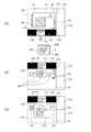
図5(A)、(C)、(D)は指示体70の操作に対応して表示が変化する例を示し、図5(B)はタブレット3における表示例を示す。
図4(C)に示した状態で、領域111に表示された画像のキャプチャーが指示体70により指示されると、制御部30は、図5(A)に示すように、表示画像P1と描画画像P3とを含む領域111の全体のキャプチャー画像P11を生成する。キャプチャー画像P11は、フレームメモリー41から領域111に対応する画像を切り出すことで生成される。領域111はタブレット2に対応付けられ、プロジェクター100がタブレット2から受信する画像データに基づく表示画像P1が表示される。換言すれば、領域111に表示される表示画像P1は、画像ソースがタブレット2に設定され、プロジェクター100が表示画像P1に対して行う処理は描画画像P3を重畳する処理、及び領域111の拡大及び縮小に伴う表示サイズの変更に限られる。
FIGS. 5A, 5 </ b> C, and 5 </ b> D show examples in which the display changes in response to the operation of the indicator 70, and FIG. 5B shows a display example on the tablet 3.
In the state shown in FIG. 4C, when capturing of the image displayed in the area 111 is instructed by the indicator 70, the control unit 30 draws the display image P1 and the drawing as shown in FIG. A capture image P11 of the entire region 111 including the image P3 is generated. The captured image P11 is generated by cutting out an image corresponding to the region 111 from the frame memory 41. The area 111 is associated with the tablet 2, and a display image P <b> 1 based on the image data received by the projector 100 from the tablet 2 is displayed. In other words, the display image P1 displayed in the area 111 is set such that the image source is set to the tablet 2, and the process performed by the projector 100 on the display image P1 is the process of superimposing the drawing image P3, Limited to display size change due to reduction.

一方、キャプチャー画像P11は、制御部30がフレームメモリー41の画像データから生成する静止画像であり、タブレット2に対応付けられていないため、制御部30の制御により送信し、保存し、或いは各種の画像処理を行うことが可能である。   On the other hand, the captured image P11 is a still image generated from the image data in the frame memory 41 by the control unit 30 and is not associated with the tablet 2. Therefore, the capture image P11 is transmitted and stored under the control of the control unit 30, or Image processing can be performed.

キャプチャー画像P11に対し、矢印A3に示すように指示体70を動かす操作が行われると、制御部30は、キャプチャー画像P11を領域114に移動する。この操作は、キャプチャー画像P11の上で先端部71をスクリーンSCに接触させ、そのまま矢印A3の方向に領域114まで先端部71を移動させる操作である。   When the operation of moving the indicator 70 is performed on the captured image P11 as indicated by the arrow A3, the control unit 30 moves the captured image P11 to the region 114. This operation is an operation of bringing the tip 71 into contact with the screen SC on the captured image P11 and moving the tip 71 to the region 114 in the direction of the arrow A3 as it is.

領域114は、複数のタブレット3に対応付けられた機器対応領域(複数機器対応領域)である。制御部30は、図5(A)における操作に応じて、キャプチャー画像P11の画像データを、領域114に対応付けられたタブレット3に送信する。タブレット3は、プロジェクター100が送信した画像データを受信して、受信した画像データに基づく画像をタッチパネル301に表示する。これにより、タブレット3のタッチパネル301には、図5(B)に示すように、キャプチャー画像P11と同じ描画画像P31が表示される。   The region 114 is a device corresponding region (multiple device corresponding region) associated with a plurality of tablets 3. The control unit 30 transmits the image data of the captured image P11 to the tablet 3 associated with the region 114 in accordance with the operation in FIG. The tablet 3 receives the image data transmitted by the projector 100 and displays an image based on the received image data on the touch panel 301. Thereby, on the touch panel 301 of the tablet 3, as shown to FIG. 5 (B), the drawing image P31 same as the capture image P11 is displayed.

ここで、複数のタブレット3のそれぞれは、表示中の描画画像P31の画像データをプロジェクター100に送信する。タブレット2及びタブレット3は、画像の表示中、所定時間毎に、表示中の画像に対応する画像データをプロジェクター100に送信してもよい。この画像データの送信は、タッチパネル301に表示する画像を更新したとき、或いは、プロジェクター100から画像データを受信したときに行ってもよい。
制御部30は、タブレット3から送信される画像データに基づき、領域114に表示する画像を更新する。
Here, each of the plurality of tablets 3 transmits the image data of the displayed drawn image P31 to the projector 100. The tablet 2 and the tablet 3 may transmit image data corresponding to the displayed image to the projector 100 at predetermined time intervals during image display. The transmission of the image data may be performed when an image displayed on the touch panel 301 is updated or when image data is received from the projector 100.
The control unit 30 updates the image displayed in the area 114 based on the image data transmitted from the tablet 3.

図5(C)にはスクリーンSCの投射画像が更新された状態を示す。この図5(C)の状態では、指示体70の操作により、領域114が拡大されている。
図5(C)では、それぞれのタブレット3でタッチパネル301の表示画像が更新されたことに対応して、表示画像P2が更新されている。
FIG. 5C shows a state where the projection image on the screen SC has been updated. In the state of FIG. 5C, the region 114 is enlarged by operating the indicator 70.
In FIG. 5C, the display image P2 is updated in response to the display image of the touch panel 301 being updated on each tablet 3.

さらに、図5(B)に示すように、タブレット3では、タッチパネル301の操作により画像を描画することも可能である。この場合、タブレット3の制御部312が、タッチパネル301に対する操作を入力部314で検出し、描画の指示、及び描画内容の指示に基づき画像を生成して、生成した画像を既に表示中の描画画像P31に重ねて表示する。これにより、タッチパネル301において、プロジェクター100から受信した画像と描画された画像とが合成され、描画画像P32が生成され表示される。
タブレット3は、描画画像P32の画像データをプロジェクター100に送信し、図5(C)に示すように、このタブレット3に対応する表示画像P2が更新される。図5(C)の例では1台のタブレット3で描画が行われたため、このタブレット3に対応する表示画像P2が更新されている。
Furthermore, as illustrated in FIG. 5B, the tablet 3 can draw an image by operating the touch panel 301. In this case, the control unit 312 of the tablet 3 detects an operation on the touch panel 301 with the input unit 314, generates an image based on the drawing instruction and the drawing content instruction, and the generated image is already displayed. Overlaid on P31. Thereby, on the touch panel 301, the image received from the projector 100 and the drawn image are combined, and the drawn image P32 is generated and displayed.
The tablet 3 transmits the image data of the drawing image P32 to the projector 100, and the display image P2 corresponding to the tablet 3 is updated as shown in FIG. In the example of FIG. 5C, since the drawing is performed by one tablet 3, the display image P2 corresponding to the tablet 3 is updated.

領域114では、複数のタブレット3に対応する表示画像P2のうち、いずれかの表示画像P2を選択してキャプチャー画像を生成できる。図5(D)には、一つの表示画像P2が選択され、キャプチャー画像P12が生成された例を示す。キャプチャー画像P12は、制御部30がフレームメモリー41から切り出した画像である。領域114はタブレット3に対応付けられているが、キャプチャー画像P12は機器への対応付けによる制限のない、静止画像であり、制御部30が送信し、保存し、その他の画像処理を行うことができる。   In the area 114, any one of the display images P2 among the display images P2 corresponding to the plurality of tablets 3 can be selected to generate a capture image. FIG. 5D shows an example in which one display image P2 is selected and a capture image P12 is generated. The captured image P12 is an image cut out from the frame memory 41 by the control unit 30. The area 114 is associated with the tablet 3, but the captured image P12 is a still image that is not limited by association with the device, and the control unit 30 can transmit, save, and perform other image processing. it can.

図6(A)、(B)、(C)は指示体70の操作に対応して表示が変化する例を示す。
図6(A)では、領域114から領域113に対し、矢印A4に示すように指示体70を動かす操作が行われる例を示す。事前の指示体70の操作により、処理の対象である表示画像P2が選択され、この例では3つの表示画像P2の全てが対象である。
この操作に応じて、制御部30は、処理の対象の表示画像P2を、領域113に移動する処理を行う。制御部30は、領域113の表示画像P2の画像をフレームメモリー41から切り出して、それぞれの表示画像P2に対応するキャプチャー画像を生成し、領域113に表示する。
FIGS. 6A, 6 </ b> B, and 6 </ b> C show examples in which the display changes in response to the operation of the indicator 70.
FIG. 6A shows an example in which an operation of moving the indicator 70 is performed from the area 114 to the area 113 as indicated by an arrow A4. The display image P2 to be processed is selected by operating the indicator 70 in advance. In this example, all three display images P2 are targets.
In response to this operation, the control unit 30 performs a process of moving the display image P2 to be processed to the area 113. The control unit 30 cuts out the image of the display image P2 in the region 113 from the frame memory 41, generates a capture image corresponding to each display image P2, and displays it in the region 113.

領域113は、上述のように処理領域であり、領域113に表示される画像等は表示オブジェクトとして独立して操作できる。このため、表示画像P2から生成されたキャプチャー画像は、図6(B)に示すように、領域113にオブジェクトO1〜O3として表示される。オブジェクトO1〜O3は、例えば図6(C)に示すように、表示位置を変更できる。また、領域113では、指示体70の操作によりメニューバーMを表示して描画を行うことが可能である。この場合、図6(C)に示すように、領域113で描画された画像は、オブジェクトO4として表示される。オブジェクトO4は、オブジェクトO1〜O3と同様に、表示位置、表示サイズ等を変更でき、個別に消去し、コピーし、保存することができる。なお、この後で、これらオブジェクトO1〜O4を、領域111または領域114に移動させる操作が行われると、制御部30は、オブジェクトO1〜O4の画像データを、タブレット2またはタブレット3に送信する。   The area 113 is a processing area as described above, and an image displayed in the area 113 can be operated independently as a display object. For this reason, the capture image generated from the display image P2 is displayed as objects O1 to O3 in the region 113 as shown in FIG. 6B. For example, as shown in FIG. 6C, the display positions of the objects O1 to O3 can be changed. In the area 113, the menu bar M can be displayed and drawn by operating the indicator 70. In this case, as shown in FIG. 6C, the image drawn in the region 113 is displayed as an object O4. As with the objects O1 to O3, the object O4 can be changed in display position, display size, etc., and can be individually erased, copied, and saved. After that, when an operation for moving these objects O1 to O4 to the region 111 or the region 114 is performed, the control unit 30 transmits the image data of the objects O1 to O4 to the tablet 2 or the tablet 3.

図7(A)、(C)は指示体70の操作に対応して表示が変化する例を示し、図7(B)はタブレット3における表示例を示す。
図7(A)は、書画カメラ4が撮影した撮影画像が領域112に表示された例を示す。領域112の表示画像P4は、書画カメラ4の撮影画像である。図7(A)では、領域112に、表示画像P4とともにメニューバーM´が表示されている。メニューバーM´は、指示体70で操作可能なアイコンを含み、各アイコンは書画カメラ4の操作に対応する。メニューバーM´のアイコンが操作されると、制御部30は、操作に対応する制御データを書画カメラ4に送信し、書画カメラ4のズーム調整、表示の停止等を実行させる。
FIGS. 7A and 7C show examples in which the display changes in response to the operation of the indicator 70, and FIG. 7B shows a display example on the tablet 3.
FIG. 7A shows an example in which a captured image captured by the document camera 4 is displayed in the area 112. The display image P4 in the area 112 is a photographed image of the document camera 4. In FIG. 7A, a menu bar M ′ is displayed in the area 112 together with the display image P4. The menu bar M ′ includes icons that can be operated with the indicator 70, and each icon corresponds to the operation of the document camera 4. When the icon on the menu bar M ′ is operated, the control unit 30 transmits control data corresponding to the operation to the document camera 4 to cause the document camera 4 to perform zoom adjustment, stop display, and the like.

図7(A)に示す矢印A5で示すように、領域112から領域114にかけて指示体70の操作が行われると、制御部30は、領域112の表示画像P4を、領域114に移動する処理を行う。領域114はタブレット3に対応付けられた機器対応領域であるため、制御部30は、表示画像P4をタブレット3に送信する処理を行う。この処理では、制御部30が、フレームメモリー41から表示画像P4に相当する領域の画像を切り出してキャプチャー画像を生成し、このキャプチャー画像の画像データをタブレット3に送信する。領域112が書画カメラ4に対応付けられ、表示画像P4が書画カメラ4の動作により更新されるのに対し、制御部30が生成するキャプチャー画像は、独立した画像データとして処理可能である。   As indicated by an arrow A5 in FIG. 7A, when the indicator 70 is operated from the region 112 to the region 114, the control unit 30 performs a process of moving the display image P4 in the region 112 to the region 114. Do. Since the region 114 is a device corresponding region associated with the tablet 3, the control unit 30 performs a process of transmitting the display image P <b> 4 to the tablet 3. In this process, the control unit 30 cuts out an image of an area corresponding to the display image P4 from the frame memory 41, generates a capture image, and transmits image data of the capture image to the tablet 3. While the area 112 is associated with the document camera 4 and the display image P4 is updated by the operation of the document camera 4, the captured image generated by the control unit 30 can be processed as independent image data.

制御部30は、キャプチャー画像を、領域114に対応付けられた全てのタブレット3に送信する。図7(A)で、領域114の一部の表示画像P2を選択する操作が行われた場合、制御部30は、選択された表示画像P2に対応するタブレット3にのみ、キャプチャー画像の画像データを送信してもよい。   The control unit 30 transmits the captured image to all the tablets 3 associated with the region 114. In FIG. 7A, when an operation for selecting a part of the display image P2 in the region 114 is performed, the control unit 30 displays the image data of the captured image only on the tablet 3 corresponding to the selected display image P2. May be sent.

キャプチャー画像が送信されたタブレット3は、図7(B)に示すように、タッチパネル301の表示画像を更新し、書画カメラ4の撮影画像である描画画像P33が、タッチパネル301に表示される。   The tablet 3 to which the captured image has been transmitted updates the display image on the touch panel 301 as shown in FIG. 7B, and a drawing image P33 that is a captured image of the document camera 4 is displayed on the touch panel 301.

また、図5(B)にも示したように、タブレット3において表示が更新されると、領域114における表示も更新される。更新後の状態を図7(C)に示す。図7(C)の例では、領域111、112、113、114のサイズが初期状態に戻されている。
図7(C)の例では、領域114において各々のタブレット3に対応する表示画像P2が、領域112からコピーされた画像で更新されている。また、領域114では3つのタブレット3に対応する3つの表示画像P2が配置されるため、表示画像P2はサムネイル画像として表示される。これに対し、領域111ではタブレット2に対応する1つの表示画像P1を表示すればよい。従って、領域112から領域111へ表示画像P4を移動した場合には、領域112の表示画像P4が、領域111の全体に表示される。つまり、領域111、112、114はいずれも機器対応領域であるが、単独の機器に対応付けられる領域111、112では一つの表示画像が全面表示され、複数の機器に対応する領域114では機器の数に応じた数の画像が表示される。領域114では一つの表示画像の表示サイズが小さくなるので、サムネイル画像を表示するよう設定できる。
Further, as shown in FIG. 5B, when the display is updated in the tablet 3, the display in the region 114 is also updated. FIG. 7C shows the state after the update. In the example of FIG. 7C, the sizes of the areas 111, 112, 113, and 114 are returned to the initial state.
In the example of FIG. 7C, the display image P2 corresponding to each tablet 3 in the area 114 is updated with the image copied from the area 112. In the region 114, since three display images P2 corresponding to the three tablets 3 are arranged, the display image P2 is displayed as a thumbnail image. On the other hand, in the area 111, one display image P1 corresponding to the tablet 2 may be displayed. Therefore, when the display image P4 is moved from the region 112 to the region 111, the display image P4 of the region 112 is displayed on the entire region 111. That is, the regions 111, 112, and 114 are all device-corresponding regions, but one display image is displayed on the entire screen in the regions 111 and 112 that are associated with a single device, and the region 114 that corresponds to a plurality of devices. The number of images corresponding to the number is displayed. In the area 114, since the display size of one display image is reduced, it can be set to display a thumbnail image.

このように、プロジェクター100の制御部30は、投射可能領域110を分割した領域111、112、113、114に画像を表示し、表示された画像を異なる領域に移動し、コピーできる。   As described above, the control unit 30 of the projector 100 can display images in the regions 111, 112, 113, and 114 obtained by dividing the projectable region 110, and can move the displayed images to different regions and copy them.

図8〜図11の各図は、プロジェクター100の動作を示すフローチャートである。図8は、プロジェクター100にタブレット2、3、書画カメラ4などの外部機器が接続された場合に実行される接続処理を示す。
接続処理は、制御部30が、インターフェース部11または画像インターフェース部12への接続を検出したときに実行される。
8 to 11 are flowcharts showing the operation of the projector 100. FIG. 8 shows a connection process executed when an external device such as the tablet 2 or 3 or the document camera 4 is connected to the projector 100.
The connection process is executed when the control unit 30 detects a connection to the interface unit 11 or the image interface unit 12.

制御部30は、インターフェース部11または画像インターフェース部12への外部機器の接続を検出し(ステップS11)、接続した機器に対応する機器対応領域を判定する(ステップS12)。本実施形態の領域111はタブレット2に対応し、領域112は書画カメラ4に対応する。また、領域113は複数のタブレット3に対応付けられる複数機器対応領域である。制御部30は、ステップS11で検出した外部機器の種類に基づき、プロジェクター100が投射可能な機器対応領域のうち、対応付ける領域を判定する。また、各機器対応領域が対応付け可能な外部機器の種類が制限されない場合、接続順に機器対応領域への対応付けを行ってもよい。また、接続される外部機器が複数ある場合に、複数機器対応領域に対応付けるよう判定してもよい。   The control unit 30 detects the connection of an external device to the interface unit 11 or the image interface unit 12 (step S11), and determines a device corresponding area corresponding to the connected device (step S12). In this embodiment, the area 111 corresponds to the tablet 2, and the area 112 corresponds to the document camera 4. An area 113 is an area corresponding to a plurality of devices associated with a plurality of tablets 3. Based on the type of external device detected in step S <b> 11, the control unit 30 determines a region to be associated among the device corresponding regions that can be projected by the projector 100. If the types of external devices that can be associated with each device-corresponding area are not limited, the association with the device-corresponding areas may be performed in the order of connection. Further, when there are a plurality of external devices to be connected, it may be determined to be associated with the multiple device corresponding area.

制御部30は、接続した外部機器から当該機器に関する情報を取得して、外部機器情報62として記憶部60に記憶し(ステップS13)、接続した外部機器から画像データを取得する(ステップS14)。制御部30は、接続した外部機器と、ステップS12で判定した機器対応領域の位置とを対応付けて、表示位置情報63として記憶部60に記憶する(ステップS15)。   The control unit 30 acquires information related to the device from the connected external device, stores it in the storage unit 60 as the external device information 62 (step S13), and acquires image data from the connected external device (step S14). The control unit 30 associates the connected external device with the position of the device corresponding area determined in step S12 and stores it in the storage unit 60 as display position information 63 (step S15).

制御部30は、サムネイル画像を生成するか否かを判定する(ステップS16)。例えば、ステップS12で判定した領域が複数機器対応領域である場合、図4(A)に示した領域114のように表示サイズが小さいためサムネイル画像を使用してもよい。サムネイル画像を使用する場合(ステップS16;Yes)、制御部30は、ステップS14で受信した画像データからサムネイル画像の画像データを生成して、ステップS12で判定した領域にサムネイル画像を表示する(ステップS17)。
また、サムネイル画像を使用しない場合(ステップS16;No)、制御部30は、ステップS14で受信した画像データに基づく画像を、ステップS12で判定した領域に表示する(ステップS18)。
The control unit 30 determines whether to generate a thumbnail image (step S16). For example, when the area determined in step S12 is a multi-device corresponding area, a thumbnail image may be used because the display size is small like the area 114 shown in FIG. When using a thumbnail image (step S16; Yes), the control unit 30 generates image data of the thumbnail image from the image data received in step S14, and displays the thumbnail image in the area determined in step S12 (step S12). S17).
When the thumbnail image is not used (step S16; No), the control unit 30 displays the image based on the image data received in step S14 in the area determined in step S12 (step S18).

図9は、画像の表示に係る動作を示すフローチャートである。
制御部30は、指示体70による操作を操作検出部50が検出した場合、検出した操作位置を取得し(ステップS21)、この操作位置を一時的にRAMや記憶部60に記憶する(ステップS22)。
続いて、制御部30は、操作の内容を判定する(ステップS23)。操作の内容は、例えば、メニューバーの表示を指示する操作、領域境界115の移動を指示する操作、投射可能領域110に表示される画像やオブジェクトを移動させる操作等である。
FIG. 9 is a flowchart showing an operation related to image display.
When the operation detection unit 50 detects an operation by the indicator 70, the control unit 30 acquires the detected operation position (step S21), and temporarily stores the operation position in the RAM or the storage unit 60 (step S22). ).
Subsequently, the control unit 30 determines the content of the operation (step S23). The contents of the operation include, for example, an operation for instructing display of a menu bar, an operation for instructing movement of the region boundary 115, an operation for moving an image or object displayed in the projectable region 110, and the like.

制御部30は、操作内容がメニューバーの呼び出しであるか否かを判定し(ステップS24)、メニューバーの呼び出しの操作であると判定した場合(ステップS24;Yes)、メニュー処理を実行し(ステップS25)、後述するステップS35に移行する。   The control unit 30 determines whether or not the operation content is a menu bar call (step S24), and when determining that the operation content is a menu bar call operation (step S24; Yes), executes the menu process ( Step S25), the process proceeds to Step S35 described later.

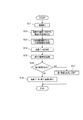
図10は、図9のステップS25で実行するメニュー処理を詳細に示すフローチャートである。
制御部30は、ステップS21(図9)で検出した操作位置を含む領域にメニューバーMの画像を表示し(ステップS51)、メニューバーMに対する操作を待機する(ステップS52)。
FIG. 10 is a flowchart showing in detail the menu process executed in step S25 of FIG.
The control unit 30 displays an image of the menu bar M in an area including the operation position detected in step S21 (FIG. 9) (step S51), and waits for an operation on the menu bar M (step S52).

制御部30は、メニューバーMのアイコンの位置における操作を検出した場合(ステップS53)、検出した操作が画像のキャプチャーを指示する操作であるか否かを判定する(ステップS53)。ステップS53の判定は、指示体70の操作位置が、メニューバーMに含まれるキャプチャー指示のアイコン上の座標であるか否かに基づき、行われる。
画像のキャプチャーの指示であると判定した場合(ステップS53;Yes)、制御部30は、メニューバーMを表示している領域のキャプチャー画像を生成し(ステップS54)、キャプチャー画像の処理に係る操作を待機する(ステップS55)。
When the operation at the position of the icon on the menu bar M is detected (step S53), the control unit 30 determines whether the detected operation is an operation for instructing image capture (step S53). The determination in step S53 is performed based on whether or not the operation position of the indicator 70 is the coordinates on the icon of the capture instruction included in the menu bar M.
If it is determined that the instruction is to capture an image (step S53; Yes), the control unit 30 generates a captured image of the area displaying the menu bar M (step S54), and performs an operation related to the processing of the captured image. (Step S55).

指示体70による操作を検出すると(ステップS55;Yes)、制御部30は、検出した操作の内容が、他の領域への画像の移動を指示する操作であるか否かを判定する(ステップS56)。他の領域への移動を指示する操作であると判定した場合(ステップS56;Yes)、制御部30は、画像を他の領域に移動させる領域移動処理を実行し(ステップS57)、ステップS59に移動する。領域移動処理については後述する。   When the operation by the indicator 70 is detected (step S55; Yes), the control unit 30 determines whether or not the content of the detected operation is an operation instructing the movement of the image to another area (step S56). ). When it is determined that the operation is an operation for instructing movement to another area (step S56; Yes), the control unit 30 executes area movement processing for moving the image to another area (step S57), and the process proceeds to step S59. Moving. The area movement process will be described later.

また、他の領域への画像の移動を指示する操作でないと判定した場合(ステップS56;No)、制御部30は、キャプチャー画像のデータを、記憶部60に記憶し(ステップS58)、ステップS59に移行する。
ステップS59で、制御部30は、メニューバーMの操作が終了したか否かを判定する。メニューバーMの表示の終了を指示する操作を検出した場合や、メニューバーMが表示されていない領域に対する操作を検出した場合に、制御部30は、メニューバーMの操作が終了したと判定する(ステップS59;Yes)。この場合、制御部30は、メニューバーMの表示を終えて(ステップS60)、本処理を終了する。
また、制御部30は、メニューバーMの操作が終了していないと判定した場合(ステップS59;No)、ステップS52に戻り、操作を待機する。
When it is determined that the operation is not an instruction to move the image to another area (step S56; No), the control unit 30 stores the captured image data in the storage unit 60 (step S58), and step S59. Migrate to
In step S59, the control unit 30 determines whether or not the operation of the menu bar M is completed. When an operation for instructing the end of the display of the menu bar M is detected, or when an operation for an area where the menu bar M is not displayed is detected, the control unit 30 determines that the operation of the menu bar M has ended. (Step S59; Yes). In this case, the control unit 30 finishes displaying the menu bar M (step S60), and ends this process.
In addition, when it is determined that the operation of the menu bar M has not ended (step S59; No), the control unit 30 returns to step S52 and waits for the operation.

一方、メニューバーMの表示中に検出した操作が、画像のキャプチャーの指示でない場合(ステップS53;No)、制御部30は、描画の指示であるか否かを判定する(ステップS61)。描画の指示であると判定した場合(ステップS61;Yes)、制御部30は、その後の指示体70の操作を検出して、操作位置の軌跡に従って描画を実行し(ステップS62)、描画したオブジェクトまたは描画した領域全体の画像データを生成して、記憶部60に記憶する(ステップS63)。図10のメニュー処理の対象の領域が、機器対応領域である場合、制御部30は、ステップS63で、描画した領域全体の画像データを生成して記憶する。この場合、生成される画像データには、外部機器から入力され表示された画像が含まれる。また、メニュー処理の対象の領域が処理領域である場合、制御部30は、ステップS63で、描画したオブジェクトの画像データを生成して記憶する。ステップS63の処理を実行した後、制御部30はステップS59に移行する。   On the other hand, when the operation detected during the display of the menu bar M is not an image capture instruction (step S53; No), the control unit 30 determines whether or not the operation is a drawing instruction (step S61). When it determines with it being an instruction | indication of drawing (step S61; Yes), the control part 30 detects operation of the indicator 70 after that, performs drawing according to the locus | trajectory of an operation position (step S62), and the drawn object Alternatively, image data of the entire drawn area is generated and stored in the storage unit 60 (step S63). When the menu processing target area in FIG. 10 is a device-corresponding area, the control unit 30 generates and stores image data of the entire drawn area in step S63. In this case, the generated image data includes an image input and displayed from an external device. If the menu processing target area is a processing area, the control unit 30 generates and stores image data of the drawn object in step S63. After executing the process of step S63, the control unit 30 proceeds to step S59.

また、指示体70により描画以外の操作が行われた場合(ステップS61;No)、制御部30は、操作の内容に対応する処理を実行し(ステップS64)、ステップS59に移行する。ステップS64で実行する処理は、例えば、描画したオブジェクトを消去する処理、描画する図形の形状、色、線の太さ等の描画に係る設定処理、オブジェクトを領域内で移動する処理などである。   When an operation other than drawing is performed by the indicator 70 (step S61; No), the control unit 30 executes a process corresponding to the content of the operation (step S64), and proceeds to step S59. The process executed in step S64 is, for example, a process for deleting a drawn object, a setting process related to drawing such as the shape, color, and line thickness of a figure to be drawn, and a process for moving an object within an area.

図9に戻り、ステップS23において操作内容がメニューバーの呼び出しの操作でないと判定した場合(ステップS24;No)、制御部30は、操作位置が領域境界115の上であるか否かを判定する(ステップS26)。指示体70による操作が連続的であり、ステップS22において一時記憶した操作位置が一つの軌跡を形成する場合、制御部30は、この軌跡の始点が、領域境界115の上または領域境界115に近接した位置であるか否かを判定する。操作位置が領域境界115の上であった場合(ステップS26;Yes)、制御部30は、指示体70の操作の軌跡に追従して領域境界115を移動させる処理を行う(ステップS27)。ステップS27では、領域境界115を移動する処理に合わせて、移動後の領域境界115の位置に基づき各領域111、112、113、114を拡大及び縮小する処理を行う。その後、制御部30は、後述するステップS35に移行する。   Returning to FIG. 9, when it is determined in step S23 that the operation content is not a menu bar call operation (step S24; No), the control unit 30 determines whether or not the operation position is on the region boundary 115. (Step S26). When the operation by the indicator 70 is continuous and the operation position temporarily stored in step S22 forms one trajectory, the control unit 30 indicates that the start point of the trajectory is above the region boundary 115 or close to the region boundary 115. It is determined whether or not it is the position. When the operation position is on the region boundary 115 (step S26; Yes), the control unit 30 performs a process of moving the region boundary 115 following the operation locus of the indicator 70 (step S27). In step S27, in accordance with the process of moving the area boundary 115, a process of enlarging and reducing each area 111, 112, 113, 114 based on the position of the moved area boundary 115 is performed. Thereafter, the control unit 30 proceeds to step S35 described later.

制御部30は、操作位置が領域境界115の上でないと判定した場合(ステップS26;No)、操作位置が、処理領域である領域113のオブジェクトの上であるか否かを判定する(ステップS28)。制御部30は、操作位置が、処理領域である領域113のオブジェクトの上であると判定した場合(ステップS28;Yes)、オブジェクトを他の領域に移動する指示であるか否かを判定する(ステップS29)。例えば、指示体70による操作が連続的であり、ステップS22において一時記憶した操作位置が一つの軌跡を形成する場合、制御部30は、この軌跡の終点が、他の領域であるか否かを判定する。他の領域への移動を指示する操作であると判定した場合(ステップS29;Yes)、制御部30は、領域移動処理を実行し(ステップS30)、ステップS35に移行する。領域移動処理の詳細は後述する。   When it is determined that the operation position is not on the region boundary 115 (step S26; No), the control unit 30 determines whether or not the operation position is on an object in the region 113 that is the processing region (step S28). ). When it is determined that the operation position is on the object in the region 113 that is the processing region (step S28; Yes), the control unit 30 determines whether the instruction is an instruction to move the object to another region (step S28). Step S29). For example, when the operation by the indicator 70 is continuous and the operation position temporarily stored in step S22 forms one trajectory, the control unit 30 determines whether or not the end point of this trajectory is another region. judge. When it determines with it being operation which instruct | indicates the movement to another area | region (step S29; Yes), the control part 30 performs an area | region movement process (step S30), and transfers to step S35. Details of the area moving process will be described later.

また、他の領域へのオブジェクトの移動を指示する操作でないと判定した場合(ステップS29;No)、制御部30は、操作に従ってオブジェクトを処理領域内で移動させる(ステップS31)。すなわちオブジェクトの表示位置を変更する処理を行い、ステップS35に移行する。   If it is determined that the operation is not an instruction to move the object to another area (step S29; No), the control unit 30 moves the object in the processing area according to the operation (step S31). That is, a process for changing the display position of the object is performed, and the process proceeds to step S35.

一方、指示体70の操作位置が、処理領域のオブジェクト上でないと判定した場合(ステップS28;No)、制御部30は、操作位置が機器対応領域にあるか否かを判定する(ステップS32)。操作位置が機器対応領域である領域111、112、114のいずれかである場合(ステップS32;Yes)、制御部30は、機器対応領域の画像を他の領域に移動する指示であるか否かを判定する(ステップS33)。他の領域への移動を指示する操作であると判定した場合(ステップS33;Yes)、制御部30は、ステップS30に移行して領域移動処理を実行する。   On the other hand, when it determines with the operation position of the indicator 70 not being on the object of a process area (step S28; No), the control part 30 determines whether an operation position exists in an apparatus corresponding | compatible area | region (step S32). . When the operation position is any one of the regions 111, 112, and 114 that are device-corresponding regions (step S32; Yes), the control unit 30 determines whether or not it is an instruction to move the image of the device-corresponding region to another region. Is determined (step S33). When it determines with it being operation which instruct | indicates the movement to another area | region (step S33; Yes), the control part 30 transfers to step S30, and performs an area | region movement process.

また、他の領域への画像の移動を指示する操作でないと判定した場合(ステップS33;No)、制御部30は、操作位置を含む領域の画像をキャプチャーしてキャプチャー画像を生成し、記憶部60に記憶し(ステップS34)、ステップS35に移行する。
また、操作位置が機器対応領域でないと判定した場合(ステップS32;No)、制御部30はステップS35に移行する。
If it is determined that the operation is not an instruction to move the image to another area (step S33; No), the control unit 30 captures an image of the area including the operation position to generate a captured image, and stores the storage unit. 60 (step S34), and the process proceeds to step S35.
Further, when it is determined that the operation position is not the device corresponding region (step S32; No), the control unit 30 proceeds to step S35.

ステップS35で、制御部30は、指示体70による操作が終了したか否かを判定する。制御部30は、例えば、指示体70やリモコン(図示略)により操作終了の指示がされた場合に、操作を終了すると判定する(ステップS35;Yes)。また、操作を終了しない場合は(ステップS35;No)、ステップS21に戻る。   In step S35, the control unit 30 determines whether or not the operation by the indicator 70 has been completed. For example, the control unit 30 determines to end the operation when an instruction to end the operation is given by the indicator 70 or a remote controller (not shown) (step S35; Yes). When the operation is not terminated (step S35; No), the process returns to step S21.

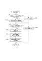
図11は、領域移動処理を詳細に示すフローチャートである。領域移動処理は、投射可能領域110内の領域111、112、113、114のうち、いずれかの領域に表示される表示画像またはオブジェクトを、他の領域に移動させる操作に対応して実行される。   FIG. 11 is a flowchart showing in detail the area movement process. The area moving process is executed in response to an operation of moving a display image or an object displayed in one of the areas 111, 112, 113, and 114 in the projectable area 110 to another area. .

制御部30は、領域移動処理において、移動元の領域が処理領域であるか否かを判定する(ステップS71)。移動元が処理領域である場合(ステップS71;Yes)、制御部30は、移動するオブジェクトの画像データを取得する(ステップS72)。また、移動元が処理領域でないと判定した場合(ステップS71;No)、移動元の領域は機器対応領域であるから、制御部30は、移動元の領域の表示画像をキャプチャーし、キャプチャー画像を生成する(ステップS73)。なお、図11の領域移動処理を開始する際に既にキャプチャー画像が生成されている場合は、ステップS71〜S73の処理は省略される。   In the area movement process, the control unit 30 determines whether or not the movement source area is a processing area (step S71). When the movement source is the processing area (step S71; Yes), the control unit 30 acquires image data of the moving object (step S72). If it is determined that the movement source is not a processing area (step S71; No), the movement source area is a device-corresponding area, so the control unit 30 captures a display image of the movement source area and displays a captured image. Generate (step S73). Note that if a captured image has already been generated when the region movement process in FIG. 11 is started, the processes in steps S71 to S73 are omitted.

続いて、制御部30は、移動先が処理領域であるか否かを判定する(ステップS74)。移動先が処理領域である場合(ステップS75)、制御部30は、移動するオブジェクトまたは移動元の領域のキャプチャー画像を、移動先の処理領域にオブジェクトとして表示し(ステップS75)、本処理を終了する。   Subsequently, the control unit 30 determines whether or not the movement destination is a processing area (step S74). When the movement destination is a processing area (step S75), the control unit 30 displays a moving object or a captured image of the movement source area as an object in the movement destination processing area (step S75), and ends this processing. To do.

一方、移動先が処理領域でない場合(ステップS74;No)、移動先は機器対応領域であるから、制御部30は、表示位置情報63を参照して、移動先の領域に対応付けられる機器を特定する(ステップS76)。制御部30は、ステップS76で特定した機器に対し、移動するオブジェクトまたは移動元の領域のキャプチャー画像の画像データを送信する(ステップS77)。さらに、制御部30は、移動するオブジェクトまたは移動元の領域のキャプチャー画像を用いて移動先の領域の表示を更新し(ステップS78)、本処理を終了する。
ステップS78で、制御部30は、ステップS77で送信した画像データを用いて表示を更新してもよい。また、ステップS77の送信先の外部機器が、画像データを受信した後にプロジェクター100に表示画像の画像データを送信した場合、この画像データを受信してスクリーンSCの投射画像を更新してもよい。
On the other hand, when the movement destination is not the processing area (step S74; No), since the movement destination is the apparatus corresponding area, the control unit 30 refers to the display position information 63 and selects the apparatus associated with the movement destination area. Specify (step S76). The control unit 30 transmits the image data of the captured image of the moving object or the movement source area to the device specified in step S76 (step S77). Further, the control unit 30 updates the display of the destination area using the captured image of the moving object or the source area (step S78), and ends this process.
In step S78, the control unit 30 may update the display using the image data transmitted in step S77. Further, when the external device of the transmission destination in step S77 transmits the image data of the display image to the projector 100 after receiving the image data, the image data may be received to update the projection image on the screen SC.

以上説明したように、本発明を適用した実施形態に係る表示システム1は、プロジェクター100と、プロジェクター100に接続される外部機器としてのタブレット2、3、及び書画カメラ4を備える。これらの外部機器はプロジェクター100に画像を出力する。プロジェクター100は、投射可能領域110に画像を表示する投射部20、外部機器に接続されるインターフェース部11及び画像インターフェース部12、及び、指示体70による操作を検出する操作検出部50を備える。また、プロジェクター100は、投射可能領域110に複数の領域111、112、113、114を設け、それぞれの領域に画像を表示させる制御部30を備える。複数の領域は、外部機器に対応付けられて外部機器に関する画像を表示する機器対応領域と、領域に表示される画像に対する処理が可能な処理領域とを含む。制御部30は、投射部20により外部機器が入力する画像を機器対応領域に表示させ、操作検出部50が検出する操作に対応して、いずれかの領域に表示される画像を他の領域に表示させる。
このため、指示体70を用いて、外部機器に対応付けられる領域に表示される画像に対し、処理を行うことが可能である。また、外部機器に対応付けられる領域の画像を、処理領域に表示させて処理を行うことにより、外部機器と表示画像との対応に影響を与えることなく、複数の画像を表示し、表示される画像に対する処理を行うことができる。
As described above, the display system 1 according to the embodiment to which the present invention is applied includes the projector 100, the tablets 2 and 3 and the document camera 4 as external devices connected to the projector 100. These external devices output an image to the projector 100. The projector 100 includes a projection unit 20 that displays an image in the projectable area 110, an interface unit 11 and an image interface unit 12 connected to an external device, and an operation detection unit 50 that detects an operation by the indicator 70. In addition, the projector 100 includes a plurality of areas 111, 112, 113, and 114 in the projectable area 110 and includes a control unit 30 that displays an image in each area. The plurality of regions include a device corresponding region that displays an image related to the external device in association with the external device, and a processing region that can process the image displayed in the region. The control unit 30 displays an image input by the external device by the projection unit 20 in the device-corresponding region, and the image displayed in one of the regions corresponding to the operation detected by the operation detection unit 50 is displayed in another region. Display.
For this reason, it is possible to perform processing on an image displayed in an area associated with an external device using the indicator 70. In addition, by displaying the image of the region associated with the external device in the processing region and performing the processing, a plurality of images are displayed and displayed without affecting the correspondence between the external device and the display image. Processing on images can be performed.

プロジェクター100の制御部30は、機器対応領域に対し、投射部20によって、外部機器に対応付けられた態様で画像を表示させる。操作検出部50が、機器対応領域に表示される画像を処理領域に移す操作を検出した場合、操作された画像の表示態様を変更可能である。これにより、外部機器に対応付けられた領域における画像について、外部機器と画像との対応に影響を与えることなく、表示態様を変更できる。   The control unit 30 of the projector 100 causes the projection unit 20 to display an image in a manner associated with the external device with respect to the device corresponding area. When the operation detection unit 50 detects an operation of moving an image displayed in the device corresponding area to the processing area, the display mode of the operated image can be changed. As a result, the display mode of the image in the region associated with the external device can be changed without affecting the correspondence between the external device and the image.

制御部30は、操作検出部50が処理領域に表示される画像を機器対応領域に移動する操作を検出した場合に、操作された画像に対して、移動先の機器対応領域に対応する外部機器に関連する処理(例えば、この外部機器に画像データを送信する処理)を行う。このため、画像を移動する操作により外部機器に関連する処理を実行させることができ、利便性の向上を図ることができる。   When the operation detection unit 50 detects an operation of moving an image displayed in the processing area to the device corresponding area, the control unit 30 performs an external device corresponding to the destination device corresponding area with respect to the operated image. (For example, processing for transmitting image data to this external device). For this reason, processing related to the external device can be executed by an operation of moving an image, and convenience can be improved.

操作検出部50は、スクリーンSCの投射可能領域110に対する操作を検出する。制御部30は、処理領域と機器対応領域とに跨がる操作を操作検出部50が検出した場合に、処理領域に表示される画像を機器対応領域に移動する操作、或いは、機器対応領域に表示される画像を処理領域に移す操作として検出する。このため、ユーザーが複数の領域に跨がる操作を行うことにより、領域に表示される画像を他の領域に移動させる処理を指示できる。   The operation detection unit 50 detects an operation on the projectable area 110 of the screen SC. When the operation detection unit 50 detects an operation that extends between the processing region and the device corresponding region, the control unit 30 moves the image displayed in the processing region to the device corresponding region or the device corresponding region. It is detected as an operation to move the displayed image to the processing area. For this reason, when the user performs an operation over a plurality of areas, it is possible to instruct a process of moving an image displayed in the area to another area.

また、制御部30は、少なくとも1つの機器対応領域に複数の外部機器を対応付けて複数機器対応領域とすることが可能である。操作検出部50が、複数機器対応領域に対し画像を移動する操作を検出した場合に、移動先の複数機器対応領域に対応付けられた複数の外部機器のそれぞれに関連する処理(例えば、複数の外部機器のそれぞれに画像データを送信する処理)を行う。このため、ユーザーが簡単な操作を行うことにより、複数の外部機器に関連する処理を実行できる。   In addition, the control unit 30 can associate a plurality of external devices with at least one device-corresponding region to form a plurality of device-corresponding regions. When the operation detection unit 50 detects an operation of moving an image with respect to the multiple device corresponding area, a process (for example, a plurality of processes) associated with each of the plurality of external devices associated with the destination multiple device corresponding area is performed. Processing for transmitting image data to each external device). For this reason, when a user performs a simple operation, processing related to a plurality of external devices can be executed.

また、制御部30は、投射部20により、複数機器対応領域に対応付けられた複数の外部機器から入力される画像を、それぞれの外部機器に対応する表示位置に表示させる。例えば、制御部30は、複数のタブレット3から送信される画像データに基づく画像を、領域114において各タブレット3に対応する位置に表示する。このため、複数の外部機器が画像を入力した場合に、これら複数の画像を見やすく表示できる。   In addition, the control unit 30 causes the projection unit 20 to display images input from a plurality of external devices associated with the plurality of device corresponding regions at display positions corresponding to the respective external devices. For example, the control unit 30 displays an image based on the image data transmitted from the plurality of tablets 3 at a position corresponding to each tablet 3 in the region 114. For this reason, when a plurality of external devices input images, the plurality of images can be displayed in an easy-to-see manner.

また、プロジェクター100は、投射部20により、インターフェース部11に接続される外部機器から入力される画像を、機器対応領域または処理領域に表示する。制御部30は、投射部20が処理領域に表示する画像の表示位置及び表示サイズの少なくともいずれかを、表示する画像を入力した外部機器に制限されず変更可能である。例えば、処理領域である領域113に移動された画像は、オブジェクトとして表示され、制御部30は、このオブジェクトの表示位置や表示サイズを変更できる。このように、プロジェクター100では、処理領域の表示画像に対し、機器対応領域に対応付けられる外部機器に関する制約を受けることなく、表示位置や表示サイズを変更できる。   Further, the projector 100 causes the projection unit 20 to display an image input from an external device connected to the interface unit 11 in the device corresponding area or the processing area. The control unit 30 can change at least one of the display position and the display size of the image displayed on the processing area by the projection unit 20 without being limited to the external device that has input the image to be displayed. For example, the image moved to the area 113 that is the processing area is displayed as an object, and the control unit 30 can change the display position and display size of the object. As described above, the projector 100 can change the display position and the display size of the display image in the processing area without being restricted by the external device associated with the device corresponding area.

また、プロジェクター100に接続される外部機器は、画像をインターフェース部11に入力する画像入力機器を含む。投射部20は、画像入力機器が入力する画像を、画像入力機器が対応付けられた機器対応領域に表示する。本実施形態では、タブレット2が送信する画像を領域111に表示し、書画カメラ4が送信する画像を領域112に表示し、タブレット3が送信する画像を領域114に表示する。このように、プロジェクター100は、画像を入力する外部機器に対応して、画像を処理できる。   The external device connected to the projector 100 includes an image input device that inputs an image to the interface unit 11. The projection unit 20 displays an image input by the image input device in a device corresponding area associated with the image input device. In the present embodiment, an image transmitted from the tablet 2 is displayed in the area 111, an image transmitted from the document camera 4 is displayed in the area 112, and an image transmitted from the tablet 3 is displayed in the area 114. Thus, the projector 100 can process an image corresponding to the external device that inputs the image.

また、プロジェクター100において、外部機器は、インターフェース部11を介して画像を入出力可能な画像入出力機器を含み、投射部20は、画像入出力機器が入力する画像を、画像入出力機器が対応付けられた機器対応領域に表示し、制御部30は、操作検出部50が、機器対応領域に対し画像を移動する操作を検出した場合に、移動先の機器対応領域に対応付けられた画像入出力機器に対して画像を出力すること、を特徴とする。
本発明によれば、外部機器が入力する画像を処理し、さらに、外部機器に対する画像の出力を行うことができる。
In the projector 100, the external device includes an image input / output device that can input and output an image via the interface unit 11, and the projection unit 20 corresponds to an image input by the image input / output device. When the operation detection unit 50 detects an operation to move an image to the device corresponding area, the control unit 30 displays the image corresponding to the destination device corresponding region. An image is output to an output device.
According to the present invention, it is possible to process an image input by an external device and further output an image to the external device.

また、制御部30は、第1の機器対応領域から処理領域に画像を移動する操作に対応して処理を行い、処理された画像について第2の機器対応領域に移動する操作を操作検出部50が検出した場合に、処理された画像を、さらに処理できる。この処理で、制御部30は、第1の機器対応領域に対応付けられた外部機器に関する制約を受けずに処理可能である。例えば、図6(A)で領域114から領域113に表示画像P2を移動した場合、表示画像P2のキャプチャー画像が、領域113にオブジェクトO1〜O3として表示される。これらオブジェクトO1〜O3を、領域111または領域114に移動させる操作が行われると、制御部30は、オブジェクトO1〜O3の画像データを、タブレット2またはタブレット3に送信する。オブジェクトO1〜O3が、タブレット3の表示画像の画像データに基づくオブジェクトであることは、オブジェクトO1〜O3の画像データを送信する処理に影響しない。従って、処理領域である領域113に移動されオブジェクトO1〜O3として表示された画像は、外部機器の属性等に影響されず、高い自由度で処理できる。このため、異なる種類の外部機器をプロジェクター100に接続する構成において、各外部機器から入力される画像を活用できる。   In addition, the control unit 30 performs processing corresponding to an operation of moving an image from the first device corresponding area to the processing region, and performs an operation of moving the processed image to the second device corresponding region on the operation detecting unit 50. If detected, the processed image can be further processed. With this processing, the control unit 30 can perform processing without being restricted by the external device associated with the first device corresponding area. For example, when the display image P2 is moved from the region 114 to the region 113 in FIG. 6A, the captured images of the display image P2 are displayed as the objects O1 to O3 in the region 113. When an operation of moving these objects O1 to O3 to the area 111 or the area 114 is performed, the control unit 30 transmits the image data of the objects O1 to O3 to the tablet 2 or the tablet 3. That the objects O1 to O3 are objects based on the image data of the display image of the tablet 3 does not affect the process of transmitting the image data of the objects O1 to O3. Therefore, the image moved to the processing area 113 and displayed as the objects O1 to O3 can be processed with a high degree of freedom without being affected by the attributes of the external device. For this reason, in a configuration in which different types of external devices are connected to the projector 100, images input from the external devices can be used.

なお、上述した実施形態及び変形例は本発明を適用した具体的態様の例に過ぎず、本発明を限定するものではなく、異なる態様として本発明を適用することも可能である。例えば、投射可能領域110に対する操作に用いる指示体は、ペン型の指示体70に限らず、ユーザーの手指、レーザーポインター、指示棒等を用いてもよく、その形状やサイズは限定されない。   Note that the above-described embodiments and modifications are merely examples of specific modes to which the present invention is applied, and the present invention is not limited thereto, and the present invention can be applied as different modes. For example, the indicator used for the operation on the projectable region 110 is not limited to the pen-type indicator 70, and a user's finger, a laser pointer, an indicator bar, or the like may be used, and the shape and size thereof are not limited.

また、上記実施形態では、操作検出部50は、撮影部51によりスクリーンSCを撮影して指示体70の位置を特定するものとしたが、本発明はこれに限定されない。例えば、撮影部51は、プロジェクター100の本体に設けられ、投射光学系23の投射方向を撮影するものに限定されない。撮影部51をプロジェクター100本体とは別体として配置してもよいし、撮影部51がスクリーンSCの側方や正面から撮影を行うものとしてもよい。さらに、複数の撮影部51を配置し、これら複数の撮影部51の撮影画像データに基づいて、対象検出部54が操作位置を検出してもよい。
また、上記実施形態では、プロジェクター100から指示体70に対し、送信部52が発する赤外線信号を用いて指示体70に同期用の信号を送信する構成を説明したが、同期用の信号は赤外線信号に限定されない。例えば、電波通信や超音波無線通信により同期用の信号を送信する構成としてもよい。
In the above-described embodiment, the operation detection unit 50 captures the screen SC by the photographing unit 51 and specifies the position of the indicator 70, but the present invention is not limited to this. For example, the photographing unit 51 is not limited to the one provided in the main body of the projector 100 and photographing the projection direction of the projection optical system 23. The imaging unit 51 may be arranged separately from the main body of the projector 100, or the imaging unit 51 may perform imaging from the side or front of the screen SC. Furthermore, a plurality of imaging units 51 may be arranged, and the target detection unit 54 may detect the operation position based on the captured image data of the plurality of imaging units 51.
In the above-described embodiment, the configuration in which the projector 100 transmits the synchronization signal to the indicator 70 using the infrared signal emitted from the transmission unit 52 to the indicator 70 has been described. However, the synchronization signal is an infrared signal. It is not limited to. For example, a synchronization signal may be transmitted by radio wave communication or ultrasonic wireless communication.

また、上述した実施形態では、指示体70の先端部71がスクリーンSCに接触しているか否かを、送受信部74の点灯パターンに基づいて判定する例を説明したが、本発明はこれに限定されない。例えば、指示体70の先端部71がスクリーンSCに押しつけられているか否かを、撮影画像データに写る指示体70及び先端部71の画像をもとに、判定してもよい。この構成は、例えば、異なる方向から撮影された複数の撮影画像データに基づいて先端部71の位置を検出したり、撮影画像データから先端部71の像と指示体70の影の像とを検出したりすることで、実現できる。
また、上述した実施形態では、プロジェクター100が内蔵する操作検出部50の機能により、指示体70の操作を検出する例を説明したが、本発明はこれに限定されない。例えば、操作検出部50の機能を、プロジェクター100とは独立した装置として実現することもできる。また、プロジェクター100以外の表示装置に、操作検出部50の機能を持たせて、位置検出装置として動作させる態様も実現可能である。
Moreover, although embodiment mentioned above demonstrated the example which determines whether the front-end | tip part 71 of the indicator 70 is contacting the screen SC based on the lighting pattern of the transmission / reception part 74, this invention is limited to this. Not. For example, whether or not the distal end portion 71 of the indicator 70 is pressed against the screen SC may be determined based on the images of the indicator 70 and the distal end portion 71 that appear in the captured image data. In this configuration, for example, the position of the tip 71 is detected based on a plurality of photographed image data photographed from different directions, and the image of the tip 71 and the shadow image of the indicator 70 are detected from the photographed image data. It can be realized by doing.
In the above-described embodiment, the example in which the operation of the indicator 70 is detected by the function of the operation detection unit 50 built in the projector 100 has been described, but the present invention is not limited to this. For example, the function of the operation detection unit 50 can be realized as a device independent of the projector 100. In addition, it is possible to realize a mode in which a display device other than the projector 100 has the function of the operation detection unit 50 and operates as a position detection device.

また、本発明の表示装置は、上述したようにスクリーンSCに画像を投射するプロジェクター100に限定されず、液晶表示パネルに画像を表示する液晶モニターまたは液晶テレビ、或いは、PDP(プラズマディスプレイパネル)に画像を表示するモニター装置またはテレビ受像機、OLED(Organic light-emitting diode)、OEL(Organic Electro-Luminescence)等と呼ばれる有機EL表示パネルに画像を表示するモニター装置またはテレビ受像機等の自発光型の表示装置など、各種の表示装置も本発明の表示システムに含まれる。この場合、液晶表示パネル、プラズマディスプレイパネル、有機EL表示パネルが表示部及び表示面に相当する。また、この表示面は、表示領域、指示体70で操作される操作面、及び操作領域に相当する。   Further, the display device of the present invention is not limited to the projector 100 that projects an image on the screen SC as described above, but may be a liquid crystal monitor or a liquid crystal television that displays an image on a liquid crystal display panel, or a plasma display panel (PDP). Self-luminous type such as a monitor device or a television receiver that displays an image on an organic EL display panel called an OLED (Organic Electro-Luminescence), etc. Various display devices such as these display devices are also included in the display system of the present invention. In this case, a liquid crystal display panel, a plasma display panel, and an organic EL display panel correspond to the display unit and the display surface. The display surface corresponds to a display area, an operation surface operated by the indicator 70, and an operation area.

また、上記実施形態では、光源が発した光を変調する光変調装置22として、RGBの各色に対応した3枚の透過型の液晶パネルを用いた構成を例に挙げて説明したが、本発明はこれに限定されるものではない。例えば、3枚の反射型液晶パネルを用いた構成としてもよいし、1枚の液晶パネルとカラーホイールを組み合わせた方式を用いてもよい。また、3枚のデジタルミラーデバイス(DMD)を用いた方式、1枚のデジタルミラーデバイスとカラーホイールを組み合わせたDMD方式等により構成してもよい。光変調装置22として1枚のみの液晶パネル又はDMDを用いる場合には、クロスダイクロイックプリズム等の合成光学系に相当する部材は不要である。また、液晶パネル及びDMD以外にも、光源が発した光を変調可能な光変調装置であれば問題なく採用できる。   In the above embodiment, the light modulation device 22 that modulates the light emitted from the light source has been described by taking as an example a configuration using three transmissive liquid crystal panels corresponding to RGB colors. Is not limited to this. For example, a configuration using three reflective liquid crystal panels may be used, or a method in which one liquid crystal panel and a color wheel are combined may be used. Alternatively, a system using three digital mirror devices (DMD), a DMD system combining one digital mirror device and a color wheel, or the like may be used. When only one liquid crystal panel or DMD is used as the light modulation device 22, a member corresponding to a synthetic optical system such as a cross dichroic prism is unnecessary. In addition to the liquid crystal panel and DMD, any light modulation device capable of modulating light emitted from the light source can be employed without any problem.

また、図2、3の機能ブロック図に示した機能ブロックは、タブレット2、3、書画カメラ4及びプロジェクター100の機能的構成を示すものであって、具体的な実装形態を制限しない。つまり、図中の機能ブロックに対応するハードウェアが実装される必要はなく、一つのプロセッサーがプログラムを実行することで複数の機能部の機能を実現する構成とすることも勿論可能である。また、上記実施形態においてソフトウェアで実現される機能の一部をハードウェアで実現してもよく、あるいは、ハードウェアで実現される機能の一部をソフトウェアで実現してもよい。
さらに、プロジェクター100に接続可能な外部機器は、タブレット2、3及び書画カメラ4に限定されない。例えば、デスクトップ型のコンピューター、スマートフォンを含む携帯型電話機、映像/音楽プレーヤー、テレビ放送のチューナー装置等、画像や音声を出力可能な装置であればよい。また、外部機器とプロジェクター100とを接続するインターフェースの具体的構成は制限されず、アナログ画像信号、音声信号あるいはデジタルデータを伝送可能なインターフェースであれば制限なく適用可能である。その他、表示システム1を構成する機器の他の各部の具体的な細部構成についても、本発明の趣旨を逸脱しない範囲で任意に変更可能である。
Moreover, the functional blocks shown in the functional block diagrams of FIGS. 2 and 3 indicate functional configurations of the tablets 2 and 3, the document camera 4, and the projector 100, and do not limit a specific mounting form. In other words, it is not necessary to implement hardware corresponding to the functional blocks in the figure, and it is of course possible to adopt a configuration in which the functions of a plurality of functional units are realized by one processor executing a program. In addition, in the above embodiment, a part of the function realized by software may be realized by hardware, or a part of the function realized by hardware may be realized by software.
Furthermore, external devices that can be connected to the projector 100 are not limited to the tablets 2 and 3 and the document camera 4. For example, any device that can output images and sounds, such as a desktop computer, a mobile phone including a smartphone, a video / music player, and a TV broadcast tuner device, may be used. The specific configuration of the interface that connects the external device and the projector 100 is not limited, and any interface that can transmit an analog image signal, an audio signal, or digital data can be applied without limitation. In addition, the specific detailed configuration of each other part of the device constituting the display system 1 can be arbitrarily changed without departing from the gist of the present invention.

1…表示システム、2…タブレット(外部機器)、3…タブレット(外部機器)、4…書画カメラ(外部機器)、11…インターフェース部(接続部)、12…画像インターフェース部(接続部)、20…投射部(表示部)、30…制御部、31…投射制御部、32…操作取得部、33…通信制御部、34…描画部、35…画像取得部、40…画像処理部、41…フレームメモリー、50…操作検出部、60…記憶部、61…制御プログラム、62…外部機器情報、63…表示位置情報、70…指示体、100…プロジェクター(表示装置)、110…投射可能領域(表示領域)、111…領域(機器対応領域)、112…領域(機器対応領域)、113…領域(処理領域)、114…領域(機器対応領域、複数機器対応領域)、115…領域境界、116…余白部、201…タッチパネル、212…制御部、301…タッチパネル、312…制御部、M、M´…メニューバー、O1〜O4…オブジェクト、SC…スクリーン。   DESCRIPTION OF SYMBOLS 1 ... Display system, 2 ... Tablet (external device), 3 ... Tablet (external device), 4 ... Document camera (external device), 11 ... Interface part (connection part), 12 ... Image interface part (connection part), 20 ... projection unit (display unit), 30 ... control unit, 31 ... projection control unit, 32 ... operation acquisition unit, 33 ... communication control unit, 34 ... drawing unit, 35 ... image acquisition unit, 40 ... image processing unit, 41 ... Frame memory 50 ... Operation detection unit 60 ... Storage unit 61 ... Control program 62 ... External device information 63 ... Display position information 70 ... Indicator 100 ... Projector (display device) 110 ... Projectable area ( Display area), 111... Area (equipment corresponding area), 112... Area (apparatus corresponding area), 113... Area (processing area), 114. Boundary, 116 ... margin, 201 ... touch panel, 212 ... controller, 301 ... touch panel, 312 ... control unit, M, M'... menu bar, O1 to O4 ... object, SC ... screen.

Claims (13)

表示領域に画像を表示する表示部と、
外部機器に接続される接続部と、
操作を検出する操作検出部と、
前記表示領域に複数の領域を設け、複数の前記領域のそれぞれに画像を表示させる制御部と、を備え、
複数の前記領域は、前記外部機器に対応付けられて前記外部機器に関する画像を表示する機器対応領域と、前記領域に表示される画像に対する処理が可能な処理領域とを含み、
前記制御部は、前記操作検出部が検出する操作に対応して、いずれかの前記領域に表示される画像を他の前記領域に表示させること、
を特徴とする表示装置。
A display unit for displaying an image in the display area;
A connection connected to an external device;
An operation detection unit for detecting an operation;
A plurality of areas in the display area, and a control unit that displays an image in each of the plurality of areas,
The plurality of regions include a device corresponding region that displays an image related to the external device in association with the external device, and a processing region that can process the image displayed in the region,
The control unit displays an image displayed in one of the regions in another region corresponding to the operation detected by the operation detection unit.
A display device.
前記制御部は、前記機器対応領域に対し、前記表示部により前記外部機器に対応付けられた態様で画像を表示させ、
前記操作検出部が前記機器対応領域に表示される画像を前記処理領域に移す操作を検出した場合に、操作された画像の表示態様を変更可能であること、
を特徴とする請求項1記載の表示装置。
The control unit displays an image in a form associated with the external device by the display unit with respect to the device corresponding region,
When the operation detection unit detects an operation of moving an image displayed in the device corresponding area to the processing area, the display mode of the operated image can be changed,
The display device according to claim 1.
前記制御部は、前記操作検出部が前記処理領域に表示される画像を前記機器対応領域に移動する操作を検出した場合に、操作された画像に対して、移動先の前記機器対応領域に対応する前記外部機器に関連する処理を行うこと、
を特徴とする請求項1または2記載の表示装置。
When the operation detection unit detects an operation of moving an image displayed in the processing area to the device corresponding area, the control unit corresponds to the device corresponding area of the movement destination with respect to the operated image. Performing processing related to the external device,
The display device according to claim 1 or 2.
前記操作検出部は、前記表示領域に対する操作を検出し、
前記制御部は、前記処理領域と前記機器対応領域とに跨がる操作を前記操作検出部が検出した場合に、前記処理領域に表示される画像を前記機器対応領域に移動する操作、或いは、前記機器対応領域に表示される画像を前記処理領域に移す操作として検出すること、
を特徴とする請求項1から3のいずれかに記載の表示装置。
The operation detection unit detects an operation on the display area,
The control unit is configured to move an image displayed in the processing region to the device corresponding region when the operation detection unit detects an operation that extends between the processing region and the device corresponding region, or Detecting an image displayed in the device corresponding area as an operation to move to the processing area;
The display device according to claim 1, wherein:
前記制御部は、少なくとも1つの前記機器対応領域に複数の前記外部機器を対応付けて複数機器対応領域とすることが可能であり、
前記操作検出部が、前記複数機器対応領域に対し画像を移動する操作を検出した場合に、移動先の前記複数機器対応領域に対応付けられた複数の前記外部機器のそれぞれに関連する処理を行うこと、
を特徴とする請求項1から4のいずれかに記載の表示装置。
The control unit can associate a plurality of external devices with at least one device-corresponding region to form a plurality of device-corresponding regions,
When the operation detection unit detects an operation of moving an image with respect to the multi-device corresponding area, processing related to each of the plurality of external devices associated with the destination multi-device corresponding area is performed. about,
The display device according to claim 1, wherein:
前記制御部は、前記表示部により、前記複数機器対応領域に対応付けられた複数の前記外部機器から入力される画像を前記複数機器対応領域に表示させる場合に、それぞれの前記外部機器に対応する表示位置に表示させること、
を特徴とする請求項5記載の表示装置。
The control unit corresponds to each external device when the display unit displays images input from the plurality of external devices associated with the multiple device corresponding region in the multiple device corresponding region. Display at the display position,
The display device according to claim 5.
前記表示部は、前記接続部に接続される前記外部機器から入力される画像を、前記機器対応領域または前記処理領域に表示し、
前記制御部は、前記表示部が前記処理領域に表示する画像の表示位置及び表示サイズの少なくともいずれかを、表示する画像を入力した前記外部機器に制限されず変更可能であること、
を特徴とする請求項1から6のいずれかに記載の表示装置。
The display unit displays an image input from the external device connected to the connection unit in the device corresponding region or the processing region,
The control unit can change at least one of a display position and a display size of an image displayed on the processing region by the display unit without being limited to the external device that has input the image to be displayed;
The display device according to claim 1, wherein:
前記外部機器は、画像を前記接続部に入力する画像入力機器を含み、
前記表示部は、前記画像入力機器が入力する画像を、前記画像入力機器が対応付けられた前記機器対応領域に表示すること、
を特徴とする請求項1から7のいずれかに記載の表示装置。
The external device includes an image input device that inputs an image to the connection unit,
The display unit displays an image input by the image input device in the device corresponding region associated with the image input device;
The display device according to claim 1, wherein:
前記外部機器は、前記接続部を介して画像を入出力可能な画像入出力機器を含み、
前記表示部は、前記画像入出力機器が入力する画像を、前記画像入出力機器が対応付けられた前記機器対応領域に表示し、
前記制御部は、前記操作検出部が、前記機器対応領域に対し画像を移動する操作を検出した場合に、移動先の前記機器対応領域に対応付けられた前記画像入出力機器に対して前記画像を出力すること、
を特徴とする請求項1から8のいずれかに記載の表示装置。
The external device includes an image input / output device capable of inputting / outputting an image via the connection unit,
The display unit displays an image input by the image input / output device in the device corresponding area associated with the image input / output device,
When the operation detection unit detects an operation of moving an image with respect to the device corresponding region, the control unit is configured to output the image to the image input / output device associated with the device corresponding region of the movement destination. Output,
The display device according to claim 1, wherein:
前記制御部は、第1の前記機器対応領域から前記処理領域に画像を移動する操作に対応して処理を行い、処理された画像について第2の前記機器対応領域に移動する操作を前記操作検出部が検出した場合に、前記処理された画像を、第1の前記機器対応領域に対応付けられた前記外部機器に関する制約を受けずに処理可能であること、
を特徴とする請求項1から9のいずれかに記載の表示装置。
The control unit performs processing corresponding to an operation of moving an image from the first device-corresponding region to the processing region, and detects the operation of moving the processed image to the second device-corresponding region. The processing unit can detect the processed image without being restricted by the external device associated with the first device corresponding region;
The display device according to claim 1, wherein:
表示装置と、表示装置に接続される外部機器とを備え、
前記外部機器は前記表示装置に画像を出力し、
前記表示装置は、
表示領域に画像を表示する表示部と、
前記外部機器に接続される接続部と、
操作を検出する操作検出部と、
前記表示領域に複数の領域を設け、複数の前記領域のそれぞれに画像を表示させる制御部と、を備え、
複数の前記領域は、前記外部機器に対応付けられて前記外部機器に関する画像を表示する機器対応領域と、前記領域に表示される画像に対する処理が可能な処理領域とを含み、
前記制御部は、前記表示部により前記外部機器が入力する画像を前記機器対応領域に表示させ、前記操作検出部が検出する操作に対応して、いずれかの前記領域に表示される画像を他の前記領域に表示させること、
を特徴とする表示システム。
A display device and an external device connected to the display device;
The external device outputs an image to the display device,
The display device
A display unit for displaying an image in the display area;
A connection unit connected to the external device;
An operation detection unit for detecting an operation;
A plurality of areas in the display area, and a control unit that displays an image in each of the plurality of areas,
The plurality of regions include a device corresponding region that displays an image related to the external device in association with the external device, and a processing region that can process the image displayed in the region,
The control unit causes the display unit to display an image input by the external device in the device corresponding region, and displays an image displayed in any of the regions corresponding to the operation detected by the operation detection unit. Displaying in the area of
A display system characterized by
表示領域に画像を表示する表示部を有し、外部機器に接続される表示装置を制御する表示装置の制御方法であって、
前記表示領域に、前記外部機器に対応付けられて前記外部機器に関する画像を表示する機器対応領域と、前記領域に表示される画像に対する処理が可能な処理領域とを含む複数の領域を設け、
複数の前記領域のそれぞれに画像を表示し、
操作を検出し、
検出した操作に対応して、いずれかの前記領域に表示される画像を他の前記領域に表示すること、
を特徴とする表示装置の制御方法。
A display device control method for controlling a display device connected to an external device having a display unit for displaying an image in a display area,
In the display area, a plurality of areas including a device corresponding area for displaying an image related to the external apparatus in association with the external apparatus, and a processing area capable of processing the image displayed in the area are provided.
Displaying an image in each of the plurality of regions,
Detect operations,
In response to the detected operation, displaying an image displayed in one of the regions in the other region,
A control method of a display device characterized by the above.
表示領域に画像を表示する表示部を有し、外部機器に接続される表示装置を制御するコンピューターが実行可能なプログラムであって、
前記表示領域に、前記外部機器に対応付けられて前記外部機器に関する画像を表示する機器対応領域と、前記領域に表示される画像に対する処理が可能な処理領域とを含む複数の領域を設け、
複数の前記領域のそれぞれに画像を表示させ、
操作に対応して、いずれかの前記領域に表示される画像を他の前記領域に表示させること、
を特徴とするプログラム。
A program that has a display unit that displays an image in a display area and that can be executed by a computer that controls a display device connected to an external device,
In the display area, a plurality of areas including a device corresponding area for displaying an image related to the external apparatus in association with the external apparatus, and a processing area capable of processing the image displayed in the area are provided.
Displaying an image in each of the plurality of regions,
In response to an operation, displaying an image displayed in one of the areas in the other area,
A program characterized by
JP2015062213A 2015-03-25 2015-03-25 Display device, display system, control method for display device, and program Withdrawn JP2016180942A (en)

Priority Applications (2)

Application Number Priority Date Filing Date Title
JP2015062213A JP2016180942A (en) 2015-03-25 2015-03-25 Display device, display system, control method for display device, and program
US15/077,281 US20160283087A1 (en) 2015-03-25 2016-03-22 Display apparatus, display system, control method for display apparatus, and computer program

Applications Claiming Priority (1)

Application Number Priority Date Filing Date Title
JP2015062213A JP2016180942A (en) 2015-03-25 2015-03-25 Display device, display system, control method for display device, and program

Publications (2)

Publication Number Publication Date
JP2016180942A true JP2016180942A (en) 2016-10-13
JP2016180942A5 JP2016180942A5 (en) 2018-04-19

Family

ID=56976535

Family Applications (1)

Application Number Title Priority Date Filing Date
JP2015062213A Withdrawn JP2016180942A (en) 2015-03-25 2015-03-25 Display device, display system, control method for display device, and program

Country Status (2)

Country Link
US (1) US20160283087A1 (en)
JP (1) JP2016180942A (en)

Cited By (1)

* Cited by examiner, † Cited by third party
Publication number Priority date Publication date Assignee Title
JP2021027415A (en) * 2019-07-31 2021-02-22 株式会社リコー Display device, display method and program

Families Citing this family (4)

* Cited by examiner, † Cited by third party
Publication number Priority date Publication date Assignee Title
KR102180479B1 (en) * 2015-07-22 2020-11-18 삼성전자주식회사 A eletronic device and an operation method of the electronic device
JP6631181B2 (en) * 2015-11-13 2020-01-15 セイコーエプソン株式会社 Image projection system, projector, and method of controlling image projection system
JP6747025B2 (en) * 2016-04-13 2020-08-26 セイコーエプソン株式会社 Display system, display device, and control method for display system
CN213513406U (en) * 2020-10-28 2021-06-22 魏俊 Projection lamp with double projection functions

Citations (4)

* Cited by examiner, † Cited by third party
Publication number Priority date Publication date Assignee Title
JP2004341678A (en) * 2003-05-14 2004-12-02 Nippon Telegr & Teleph Corp <Ntt> Window control device, method and program, and recording medium with the program recorded
US20110060992A1 (en) * 2009-09-07 2011-03-10 Jevons Oliver Matthew Video-collaboration apparatus and method
JP2011197348A (en) * 2010-03-19 2011-10-06 Seiko Epson Corp Image display system, image display method, and image display device
JP2014146097A (en) * 2013-01-28 2014-08-14 Sharp Corp Information sharing system, information display device, terminal device, and control method for information sharing system

Family Cites Families (7)

* Cited by examiner, † Cited by third party
Publication number Priority date Publication date Assignee Title
US5712995A (en) * 1995-09-20 1998-01-27 Galileo Frames, Inc. Non-overlapping tiling apparatus and method for multiple window displays
US7383308B1 (en) * 2004-02-11 2008-06-03 Aol Llc, A Delaware Limited Liability Company Buddy list-based sharing of electronic content
US9165281B2 (en) * 2005-06-07 2015-10-20 Hewlett-Packard Development Company, L.P. System and method for enabling electronic presentations
US8473851B2 (en) * 2008-02-27 2013-06-25 Cisco Technology, Inc. Multi-party virtual desktop
US9129258B2 (en) * 2010-12-23 2015-09-08 Citrix Systems, Inc. Systems, methods, and devices for communicating during an ongoing online meeting
US10523804B2 (en) * 2011-09-16 2019-12-31 Samsung Electronics Co., Ltd. Method and system for searching for object in network
US9489114B2 (en) * 2013-06-24 2016-11-08 Microsoft Technology Licensing, Llc Showing interactions as they occur on a whiteboard

Patent Citations (4)

* Cited by examiner, † Cited by third party
Publication number Priority date Publication date Assignee Title
JP2004341678A (en) * 2003-05-14 2004-12-02 Nippon Telegr & Teleph Corp <Ntt> Window control device, method and program, and recording medium with the program recorded
US20110060992A1 (en) * 2009-09-07 2011-03-10 Jevons Oliver Matthew Video-collaboration apparatus and method
JP2011197348A (en) * 2010-03-19 2011-10-06 Seiko Epson Corp Image display system, image display method, and image display device
JP2014146097A (en) * 2013-01-28 2014-08-14 Sharp Corp Information sharing system, information display device, terminal device, and control method for information sharing system

Cited By (2)

* Cited by examiner, † Cited by third party
Publication number Priority date Publication date Assignee Title
JP2021027415A (en) * 2019-07-31 2021-02-22 株式会社リコー Display device, display method and program
JP7342501B2 (en) 2019-07-31 2023-09-12 株式会社リコー Display device, display method, program

Also Published As

Publication number Publication date
US20160283087A1 (en) 2016-09-29

Similar Documents

Publication Publication Date Title
JP6064319B2 (en) Projector and projector control method
US20170142379A1 (en) Image projection system, projector, and control method for image projection system
US10989993B2 (en) Control device for correcting projection image, projection system, method of controlling same, and storage medium
JP5585505B2 (en) Image supply apparatus, image display system, image supply apparatus control method, image display apparatus, and program
JP5849560B2 (en) Display device, projector, and display method
JP6953692B2 (en) Display device and control method of display device
JP6326895B2 (en) POSITION DETECTION DEVICE, POSITION DETECTION SYSTEM, AND POSITION DETECTION DEVICE CONTROL METHOD
JP6307852B2 (en) Image display device and method for controlling image display device
US20170024031A1 (en) Display system, display device, and display control method
JP6349838B2 (en) POSITION DETECTION DEVICE, POSITION DETECTION SYSTEM, AND POSITION DETECTION DEVICE CONTROL METHOD
US10536627B2 (en) Display apparatus, method of controlling display apparatus, document camera, and method of controlling document camera
JP2016180942A (en) Display device, display system, control method for display device, and program
JP2018087950A (en) Projection system, and method for controlling projection system
JP2018088663A (en) Projector and projector control method
JP6766716B2 (en) Information processing equipment, image display program, image display method and display system
JP6269801B2 (en) Projector and projector control method
JP2016163228A (en) Display device
JP6409312B2 (en) Display system, display device, and display control method
JP2018132769A (en) Image display device, and control method of image display device
JP2019041250A (en) Display device and control method of display device
JP6545034B2 (en) Display device, display method and display system
JP6596935B2 (en) Display device, display system, and display device control method
JP2020079895A (en) Projector, projection system, control method of projector, projection method, and program
JP2012242927A (en) Mobile terminal device, control method for mobile terminal device, and program
JP6531770B2 (en) Display control apparatus, display control method, and program

Legal Events

Date Code Title Description
A521 Request for written amendment filed

Free format text: JAPANESE INTERMEDIATE CODE: A523

Effective date: 20180309

A621 Written request for application examination

Free format text: JAPANESE INTERMEDIATE CODE: A621

Effective date: 20180309

A131 Notification of reasons for refusal

Free format text: JAPANESE INTERMEDIATE CODE: A131

Effective date: 20181204

A977 Report on retrieval

Free format text: JAPANESE INTERMEDIATE CODE: A971007

Effective date: 20181121

A761 Written withdrawal of application

Free format text: JAPANESE INTERMEDIATE CODE: A761

Effective date: 20181210