以下には、図面を参照して、この発明の実施形態について具体的に説明する。図1は、遊技施設に設けられるシステム構成の概要を示す図である。図1を参照して、この発明に係る遊技媒体計数システム100は、遊技台1と、貸出装置2と、島コントローラ80と、管理装置90とで構成されている。
Embodiments of the present invention will be specifically described below with reference to the drawings. FIG. 1 is a diagram showing an outline of a system configuration provided in a game facility. Referring to FIG. 1, a game medium counting system 100 according to the present invention includes a game table 1, a lending device 2, an island controller 80, and a management device 90.
遊技施設において、遊技台1は、所定の台数毎にまとめて設置されており、まとめて配置された遊技台1は、1つの島を構成している。同様の島が、遊技施設内に幾つもある。それぞれの島は、遊技施設の一部を構成している。貸出装置2は、各遊技台1に1対1で対応して設けられている。貸出装置2は、遊技台1で遊技するためのパチンコ玉やメダル等の遊技媒体(以下では、メダルMとする。)を貸し出す機能や、遊技によって遊技台1から獲得されたメダルMを計数する機能を有している。貸出装置2は、対応する遊技台1とともに遊技施設に設置されて、前述した島を構成している。各島の遊技台1および貸出装置2は、各島に1台ずつ設けられた島コントローラ80に対して、バス85を介して接続されている。
In the gaming facility, the gaming machines 1 are collectively installed for each predetermined number, and the gaming machines 1 arranged together constitute one island. There are several similar islands in the amusement facility. Each island is part of a gaming facility. The lending device 2 is provided in one-to-one correspondence with each gaming machine 1. The lending device 2 counts the medal M acquired from the gaming table 1 by the function of lending gaming media (hereinafter referred to as a medal M) such as pachinko balls and medals for playing on the gaming table 1 and the gaming machine 1. It has a function. The lending device 2 is installed in a game facility together with the corresponding game machine 1, and constitutes the aforementioned island. The game machine 1 and the lending device 2 of each island are connected via a bus 85 to an island controller 80 provided for each island.
各島コントローラ80は、バス95を介して管理装置90に対して接続されている。島コントローラ80は、担当する島の遊技台1および貸出装置2のそれぞれと管理装置90との間を中継するとともに、担当する島の情報を管理する。管理装置90は、遊技施設において上位に位置する装置であって、ターミナルコントローラとも呼ばれ、各遊技台1や各貸出装置2における遊技媒体の出入り等を管理する。管理装置90は、遊技施設において、従業員用の事務所等に配置されている。
Each island controller 80 is connected to the management device 90 via a bus 95. The island controller 80 relays between the management device 90 and each of the gaming table 1 and the lending device 2 of the island in charge, and manages information of the island in charge. The management device 90 is a higher-level device in the gaming facility, and is also called a terminal controller, and manages the entry / exit of game media in each gaming machine 1 and each rental device 2. The management device 90 is arranged in an office for employees in a game facility.
メダルMは、金属製の小さな円板である(後述する図11(a)参照)。遊技施設では、メダルMを遊技客に貸し出す際のレートである貸出レートが複数設定されていて、メダルMの色が貸出レート毎に異なる場合がある。この場合、メダルMの貸出レートは、そのメダルMの色によって区別される。この実施形態では、メダルMの1枚あたりの貸出レートが、5円/枚、10円/枚および20円/枚というように3つ設定されている。貸出レートが5円/枚のメダルMは銀一色であり、貸出レートが10円/枚のメダルMの色は金一色である。貸出レートが20円/枚のメダルMは、円中心側の内側部分MAが金色で外周部分MBが銀色という具合に2色で色取られており(図11(a)参照)、このメダルMを、以下では「バイメダルM」と呼ぶことにする。前述した島は、貸出レート毎に分けられており、それぞれ島の遊技台1では、対応する貸出レートのメダルMだけを遊技に用いることができる。なお、複数の島で貸出レートが同じであってもよく、貸出レートが同じである複数の島は、この貸出レート専用の遊技コーナーを構成する。
The medal M is a small disk made of metal (see FIG. 11A described later). In the gaming facility, a plurality of lending rates, which are rates at which the medal M is lent to the player, are set, and the color of the medal M may differ for each lending rate. In this case, the rental rate of the medal M is distinguished by the color of the medal M. In this embodiment, three lending rates per medal M are set such as 5 yen / card, 10 yen / card, and 20 yen / card. A medal M with a lending rate of 5 yen / sheet is a single color of silver, and a medal M with a lending rate of 10 yen / sheet is a color of gold. The medal M with a lending rate of 20 yen / sheet is colored in two colors such that the inner part MA on the center side of the circle is gold and the outer peripheral part MB is silver (see FIG. 11A). Will be referred to as “by medal M” below. The islands described above are divided according to the lending rate, and only the medals M of the corresponding lending rate can be used in the game at the gaming table 1 of each island. The lending rate may be the same on a plurality of islands, and a plurality of islands having the same lending rate constitute a gaming corner dedicated to this lending rate.
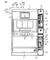
図2は、遊技台1と、この発明の一実施形態に係る貸出装置2とのセットを正面から見た図である。図3は、遊技台1および貸出装置2のセットの右側面図である。
FIG. 2 is a front view of a set of the gaming table 1 and the lending device 2 according to one embodiment of the present invention. FIG. 3 is a right side view of the set of the gaming table 1 and the lending device 2.
図2を参照して、この実施形態の遊技台1は、一般的なスロットマシンであり、その基本構成として、本体3と、投入口4と、複数列(ここでは3列)のリール5と、リール5と同じ数だけ設けられたボタン6と、受皿7とを含んでいる。投入口4、リール5、ボタン6および受皿7は、本体3の正面に設けられている。特に、受皿7は、本体3において遊技客の手が届きやすい下端部に配置されている。リール5の外周面には、様々な絵柄が周方向に1つずつ並んで形成されている。この実施形態では、遊技施設に複数の遊技台1が設置されている。
Referring to FIG. 2, a gaming table 1 of this embodiment is a general slot machine, and as a basic configuration thereof, a main body 3, a slot 4, a plurality of rows (here, three rows) of reels 5 and The button 6 provided as many as the reel 5 and the tray 7 are included. The insertion slot 4, the reel 5, the button 6 and the tray 7 are provided on the front surface of the main body 3. In particular, the tray 7 is disposed at the lower end of the main body 3 that is easy for a player to reach. On the outer peripheral surface of the reel 5, various patterns are formed one by one in the circumferential direction. In this embodiment, a plurality of game tables 1 are installed in a game facility.
遊技客は、遊技台1が設置された遊技施設から事前に貸し出してもらったメダルMを投入口4に投入する。すると、全てのリール5が回転するので、各リール5に対応するボタン6を押すことで、それぞれのリール5の回転を停止させる。回転が停止した後の全てのリール5において正面側に露出された部分の絵柄が所定のパターンになっていれば、遊技客は遊技に勝ったことになり、勝ち分のメダルMが遊技台1から受皿7に払い出される。受皿7には、遊技で獲得したメダルMだけでなく、これから遊技をするために用いるメダルMを溜めることもできる。
The player inserts the medal M, which has been lent out in advance, from the gaming facility where the gaming table 1 is installed, into the insertion slot 4. Then, since all the reels 5 rotate, pressing the button 6 corresponding to each reel 5 stops the rotation of each reel 5. If all of the reels 5 after the rotation stops and the pattern exposed on the front side has a predetermined pattern, the player has won the game, and the winning medal M is the gaming table 1. Is paid out to the tray 7. The tray 7 can store not only medals M acquired by games, but also medals M used for playing games.
以下では、正面視における貸出装置2の左右方向X、前後方向Yおよび上下方向Zを基準として、貸出装置2について説明する。前後方向Yは、図2の紙面に直交する所定方向である。前後方向Yは、図2の紙面手前側である前側Y1と、図2の紙面奥側である後側Y2とによって構成される。前側Y1は、前述した所定方向における一方側であり、後側Y2は、所定方向における一方側とは反対の他方側である。上下方向Zは、上側Z1と下側Z2とによって構成される。左右方向Xは、上側Z1から見た平面視において前後方向Yに直交する第1直交方向であり、左側X1と右側X2とによって構成される。左右方向Xおよび前後方向Yは、水平方向Hに含まれる。
Below, the lending device 2 is demonstrated on the basis of the left-right direction X, the front-back direction Y, and the up-down direction Z of the lending device 2 in front view. The front-rear direction Y is a predetermined direction orthogonal to the paper surface of FIG. The front-rear direction Y is configured by a front side Y1 that is the front side of the paper surface of FIG. 2 and a rear side Y2 that is the back side of the paper surface of FIG. The front side Y1 is one side in the predetermined direction described above, and the rear side Y2 is the other side opposite to the one side in the predetermined direction. The vertical direction Z is constituted by an upper side Z1 and a lower side Z2. The left-right direction X is a first orthogonal direction orthogonal to the front-rear direction Y in a plan view viewed from the upper side Z1, and is configured by a left side X1 and a right side X2. The left-right direction X and the front-rear direction Y are included in the horizontal direction H.
貸出装置2は、対応する遊技台1に横隣(図2の場合には右隣)に設置されている。そのため、遊技客は、自身が遊技する遊技台1の前に居たままの状態で、貸出装置2から遊技のためのメダルMを貸し出してもらったり、遊技で獲得したメダルを貸出装置2で計数してもらったりすることができる。遊技台1が貸出レート毎に分けられているので、貸出装置2では、対応する遊技台1で遊技できる貸出レートのメダルMだけが正のメダルMとされ、このメダルMとは色が異なるメダルMは否のメダルMとされる。否のメダルMには、正のメダルMと貸出レートが異なるメダルMだけでなく、別の遊技施設のメダルMや偽のメダルも含まれる。
The lending device 2 is installed next to the corresponding gaming machine 1 (next to the right in the case of FIG. 2). For this reason, the player can rent a medal M for gaming from the lending device 2 while remaining in front of the gaming table 1 on which he / she plays, or count the medals acquired by the game with the lending device 2. I can have you do it. Since the gaming machine 1 is divided according to the lending rate, in the lending device 2, only the medal M of the lending rate that can be played on the corresponding gaming machine 1 is set as the positive medal M, and the medal is different in color from the medal M. M is a no medal M. The rejection medal M includes not only the medal M having a loan rate different from that of the positive medal M, but also a medal M of another amusement facility and a fake medal.
遊技施設において、複数の遊技台1が左右方向Xに並んで配置されている場合、貸出装置2は、隣り合う遊技台1の間に配置されている。このように配置される貸出装置2は、遊技台1に比べてだいぶ幅狭に構成されている。左右方向Xにおける貸出装置2の幅は、たとえば100mm程度である。貸出装置2は、前後方向Yに奥行きを有する(図3参照)。
In a gaming facility, when a plurality of gaming machines 1 are arranged in the left-right direction X, the lending device 2 is arranged between adjacent gaming machines 1. The lending device 2 arranged in this way is configured to be much narrower than the gaming table 1. The width of the lending device 2 in the left-right direction X is, for example, about 100 mm. The lending device 2 has a depth in the front-rear direction Y (see FIG. 3).
貸出装置2は、その筐体をなす装置本体10を備えている。装置本体10には、上側Z1から順に、処理部11と、補充部12と、払出投入部13とが主に設けられている。
The lending device 2 includes a device main body 10 that forms the housing. The apparatus main body 10 is mainly provided with a processing unit 11, a replenishment unit 12, and a payout input unit 13 in order from the upper side Z1.
処理部11は、貸出装置2からメダルMを貸し出してもらうのに必要な貨幣やカードを受け付けるものである。ここでの貨幣として、この実施形態では、所定金種(たとえば千円)の紙幣が挙げられる。また、カードには、メダルMと交換できるプリペイド価値の度数を記憶したプリペイドカードや、遊技施設に会員登録した遊技客に配布される会員カードや、会員登録していない遊技客が当日獲得したメダルMの獲得数を記憶する一般カードが挙げられる。一般カードに記憶された獲得数は、持メダル数(もちめだるすう)と呼ばれる。会員カードには、持メダル数以外に、当日よりも前に獲得してその後の遊技や景品交換に用いられていないメダルMの数が、貯メダル数(ちょめだるすう)として記憶される。なお、持メダル数や貯メダル数は、一般カードや会員カードに記憶されるのではなく、これらのカードのIDに関連付けて管理装置90等に記憶されてもよい。
The processing unit 11 receives money and cards necessary for renting the medal M from the lending device 2. As the money here, in this embodiment, banknotes of a predetermined denomination (for example, 1,000 yen) are listed. Also, the card includes a prepaid card that stores the frequency of the prepaid value that can be exchanged for the medal M, a membership card that is distributed to a player registered as a member of a gaming facility, and a medal that a player who has not registered as a member has acquired that day. The general card which memorizes the number of acquisition of M is mentioned. The acquired number stored in the general card is called the number of medals held. In addition to the number of medals, the member card stores the number of medals M acquired before the current day and not used for subsequent games or prize exchanges as the number of stored medals. . Note that the number of medals and the number of stored medals may be stored in the management device 90 or the like in association with IDs of these cards, instead of being stored in the general card or the membership card.
一般カードに記憶された持メダル数は当日限り有効であり、遊技客は、当日においては、現金やプリペイドカードで新たにメダルMを貸し出してもらわなくても、持メダル数分のメダルMを用いて遊技をすることができる。当日の営業時間が終了すると、一般カードに記憶された持メダル数は、消滅してしまうが、会員カードに記憶された持メダル数は、貯メダル数となって、翌日以降の遊技や景品交換に用いることができる。
The number of medals stored on the general card is valid only for the day, and the player uses the medals M for the number of medals on the day without having to rent a medal M with cash or a prepaid card. Can play games. At the end of the business day of the day, the number of medals stored on the general card will disappear, but the number of medals stored on the membership card will become the number of stored medals, and games and prizes will be exchanged on the following day. Can be used.
装置本体10の前面10Aにおいて処理部11と一致する部分には、紙幣やカードを受け入れるための縦長の受入口14が形成されている。受入口14に投入された紙幣は、処理部11によって装置本体10内に取り込まれて識別されたり計数されたりする。受入口14に投入されたカードは、処理部11によって装置本体10内に取り込まれる。処理部11は、カードに記憶された内容を読み取ったり、書き換えたりでき、さらに、カードを受入口14から装置本体10外に排出できる。なお、受入口14は、紙幣用とカード用とで別々に設けられてもよい。
In the front surface 10A of the apparatus main body 10, a vertically long inlet 14 for receiving banknotes and cards is formed at a portion that coincides with the processing unit 11. The bills inserted into the receiving port 14 are taken into the apparatus main body 10 by the processing unit 11 and identified or counted. The card inserted into the receiving port 14 is taken into the apparatus main body 10 by the processing unit 11. The processing unit 11 can read or rewrite the contents stored in the card, and can discharge the card from the receiving port 14 to the outside of the apparatus main body 10. In addition, the receiving port 14 may be provided separately for bills and cards.
装置本体10の前面10Aにおいて受入口14の右隣の領域には、表示操作部15が設けられている。表示操作部15は、液晶のタッチパネルであり、遊技客や遊技施設の従業員に向けた情報を表示したり、テンキー等のボタン(図示せず)を表示したりすることができる。たとえば、会員登録している遊技客は、会員カードを受入口14に挿入した後に、表示操作部15に表示されたテンキーを操作して自身のパスワードを入力することによって本人認証することができる。
A display operation unit 15 is provided in a region adjacent to the right side of the receiving port 14 on the front surface 10 </ b> A of the apparatus main body 10. The display operation unit 15 is a liquid crystal touch panel, and can display information for a player or an employee of a game facility, or can display a button (not shown) such as a numeric keypad. For example, a player who has registered as a member can authenticate himself / herself by inserting a membership card into the receiving port 14 and then operating the numeric keypad displayed on the display operation unit 15 to input his / her password.
補充部12は、鍵穴16が形成された補充扉17を含む。補充扉17は、装置本体10の前面10Aに露出されている。従業員は、専用の鍵(図示せず)を鍵穴16に差し込むことで補充扉17を開くことができ、これによって、装置本体10内にアクセスして、貸出用の予備のメダルMを装置本体10内に補充したり、装置本体10の内部をメンテナンスしたりすることができる。なお、メダルMの補充は、従業員による手作業によって行われてもよいし、専用の補充装置によって自動的に行われてもよい。
The replenishment part 12 includes a replenishment door 17 in which a keyhole 16 is formed. The replenishment door 17 is exposed on the front surface 10 </ b> A of the apparatus main body 10. The employee can open the replenishment door 17 by inserting a dedicated key (not shown) into the key hole 16, thereby accessing the inside of the apparatus main body 10 and supplying a spare medal M for lending. 10 can be replenished or the inside of the apparatus main body 10 can be maintained. Note that the replenishment of medals M may be performed manually by an employee or automatically by a dedicated replenishing device.
払出投入部13は、供給ホッパー20と、供給路21と、投入皿22と、投入路23と、遊技媒体計数装置としてのメダル計数装置24とを含む。
The payout input unit 13 includes a supply hopper 20, a supply path 21, an input tray 22, an input path 23, and a medal counting device 24 as a game medium counting device.
供給ホッパー20は、上側Z1へ臨む開口部(図示せず)を有する中空体であって、装置本体10内において補充部12の真下に配置されており、貸出用の予備のメダルMが、この開口部から供給ホッパー20に補充される。
The supply hopper 20 is a hollow body having an opening (not shown) facing the upper side Z1, and is disposed immediately below the replenishment section 12 in the apparatus main body 10. A spare medal M for lending is provided The supply hopper 20 is replenished from the opening.
供給路21は、装置本体10の前面10Aにおいて左側X1に偏った領域に露出されたダクトである。供給路21の少なくとも一部は、上側Z1へ開放された略U字の断面を有する樋状に形成されてもよい。供給路21は、供給ホッパー20から前側Y1かつ下側Z2へ延びた後に、折れ曲がって左側X1かつ下側Z2へ延びている(図3も参照)。遊技客が、たとえば表示操作部15に表示された貸出ボタン(図示せず)を押すと、太い実線矢印で示すように、供給ホッパー20内のメダルMが所定数だけ供給路21を流れ落ちて遊技客に供給される。供給路21の下端を遊技台1の受皿7に向けておけば、供給路21を流れ落ちたメダルは、受皿7に直接受け入れられる。
The supply path 21 is a duct exposed in a region deviated to the left side X1 on the front surface 10A of the apparatus main body 10. At least a part of the supply path 21 may be formed in a bowl shape having a substantially U-shaped cross section opened to the upper side Z1. The supply path 21 extends from the supply hopper 20 to the front side Y1 and the lower side Z2, and then bends and extends to the left side X1 and the lower side Z2 (see also FIG. 3). When the player presses a lending button (not shown) displayed on the display operation unit 15, for example, as shown by a thick solid line arrow, a predetermined number of medals M in the supply hopper 20 flow down the supply path 21 to play the game. Supplied to customers. If the lower end of the supply path 21 is directed toward the tray 7 of the game table 1, medals flowing down the supply path 21 are directly received by the tray 7.
投入皿22は、装置本体10の前面10Aにおいて供給路21の上側Z1に配置されていて、前面10Aから前側Y1へはみ出している。遊技客は、遊技で獲得したメダルMを計数してもらいたい場合には、遊技台1の受皿7に溜まったメダルMを掴んで投入皿22に上側Z1から投入する。投入路23は、装置本体10の前面10Aにおいて供給路21の右隣に配置されたダクトである。投入路23は、投入皿22から下側Z2へ延びた後に、後側Y2へ折れ曲がって装置本体10内に延びている(図3も参照)。投入皿22に投入されたメダルMは、太い破線矢印で示すように、投入路23を通って装置本体10内に前側Y1から流れ落ちる。
The input tray 22 is disposed on the upper side Z1 of the supply path 21 on the front surface 10A of the apparatus main body 10, and protrudes from the front surface 10A to the front side Y1. When the player wants to count the medals M acquired in the game, the player grabs the medals M accumulated in the tray 7 of the game table 1 and inserts them into the loading tray 22 from the upper side Z1. The input path 23 is a duct arranged on the right side of the supply path 21 on the front surface 10 </ b> A of the apparatus main body 10. The input path 23 extends from the input tray 22 to the lower side Z2, then bends to the rear side Y2, and extends into the apparatus main body 10 (see also FIG. 3). The medal M inserted into the input tray 22 flows down from the front side Y1 into the apparatus main body 10 through the input path 23 as indicated by a thick broken line arrow.
メダル計数装置24は、投入皿22に投入されて投入路23を通って装置本体10内に流れ落ちたメダルMを計数する装置であって、装置本体10内の最下部に搭載されている。なお、メダル計数装置24においてメダルMが計数されているときには、装置本体10の前面10Aにおいて投入皿22の上側Z1に設けられたランプ25が点灯する。
The medal counting device 24 is a device that counts medals M that have been thrown into the loading tray 22 and flown into the device main body 10 through the loading path 23, and is mounted on the lowermost portion of the device main body 10. When the medal counting device 24 counts the medal M, the lamp 25 provided on the upper side Z1 of the loading tray 22 on the front surface 10A of the apparatus main body 10 is turned on.
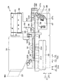
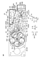
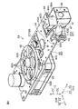
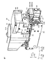
次に、メダル計数装置24について詳しく説明する。図4は、メダル計数装置24の右側面図である。なお、説明の便宜上、図4では、本来は隠れて見えない部分も実線で図示されている。図5は、メダル計数装置24の要部の平面図である。図6は、メダル計数装置24の要部の斜視図である。図7は、メダル計数装置24の全体の斜視図である。
Next, the medal counting device 24 will be described in detail. FIG. 4 is a right side view of the medal counting device 24. For convenience of explanation, in FIG. 4, portions that are originally hidden and cannot be seen are also shown by solid lines. FIG. 5 is a plan view of the main part of the medal counting device 24. FIG. 6 is a perspective view of a main part of the medal counting device 24. FIG. 7 is an overall perspective view of the medal counting device 24.
図4を参照して、メダル計数装置24は、貸出装置2と同様に、前後方向Yに奥行きを有する。メダル計数装置24の前後方向Yの奥行き寸法は、たとえば250mm程度である。メダル計数装置24は、ベース部30と、収納部31と、投出部32と、駆動部33と、搬送路34と、計数部35と、識別部36と、切換部の一例としての振分部37と、リジェクト部38と、切換部の一例としての制御部39とを含む。
With reference to FIG. 4, the medal counting device 24 has a depth in the front-rear direction Y, similarly to the lending device 2. The depth dimension of the medal counting device 24 in the front-rear direction Y is, for example, about 250 mm. The medal counting device 24 includes a base unit 30, a storage unit 31, a throwing unit 32, a drive unit 33, a transport path 34, a counting unit 35, an identification unit 36, and a distribution unit as an example of a switching unit. A unit 37, a reject unit 38, and a control unit 39 as an example of a switching unit are included.
ベース部30は、たとえば金属製であり、前後方向Yに長手のボックス状に形成されている。左右方向Xにおけるベース部30の幅は、たとえば85mm程度である。ベース部30の上壁40は、平面視において前後方向Yに長手の長方形状であり(図5参照)、その上面40Aは、水平方向Hに沿って平坦である。
The base portion 30 is made of, for example, metal and is formed in a box shape that is long in the front-rear direction Y. The width of the base portion 30 in the left-right direction X is about 85 mm, for example. The upper wall 40 of the base portion 30 has a rectangular shape that is long in the front-rear direction Y in plan view (see FIG. 5), and the upper surface 40A thereof is flat along the horizontal direction H.
収納部31は、下側Z2へ向かうにつれて前後方向Yに細くなったホッパー状に形成されている。収納部31の下端部には、収納部31の内部空間を下側Z2に露出させる円形状の開口31Aが形成されている。収納部31は、ベース部30の上壁40の略前半分の領域に対して上側Z1から取り付けられていて、開口31Aは、上壁40の上面40Aを上側Z1から臨んでいる。前述した投入路23の下端部は、収納部31の内部空間に対して前側Y1かつ上側Z1からつながっている。そのため、投入皿22のメダルMは、投入路23を前側Y1かつ上側Z1から流れ落ちることによってメダル計数装置24に対して前側Y1から投入された後に、収納部31内に収納される。メダルMは、収納部31内において、その下端部の開口31A側から溜まっていく。
The storage portion 31 is formed in a hopper shape that becomes thinner in the front-rear direction Y toward the lower side Z2. A circular opening 31 </ b> A that exposes the internal space of the storage portion 31 to the lower side Z <b> 2 is formed at the lower end of the storage portion 31. The storage portion 31 is attached to the substantially front half region of the upper wall 40 of the base portion 30 from the upper side Z1, and the opening 31A faces the upper surface 40A of the upper wall 40 from the upper side Z1. The lower end portion of the charging path 23 described above is connected to the internal space of the storage portion 31 from the front side Y1 and the upper side Z1. Therefore, the medal M on the insertion tray 22 is stored in the storage unit 31 after being inserted from the front side Y1 into the medal counting device 24 by flowing down the insertion path 23 from the front side Y1 and the upper side Z1. The medals M accumulate in the storage part 31 from the opening 31A side at the lower end thereof.
投出部32は、収納部31に溜まったメダルMを開口31Aから取り出して、1枚ずつ後側Y2へ投出するものである。投出部32は、上下方向Zに薄いディスク状に形成されており、上壁40上に配置された状態で、収納部31の開口31Aに嵌め込まれて開口31Aを下側Z2から塞いでいる。投出部32には、投出部32を上下方向Zに貫通する円形状の貫通穴32Aが、投出部32の周方向に沿って等間隔で複数形成されている(図5も参照)。貫通穴32Aの直径は、メダルMの直径よりも僅かに大きい。貫通穴32Aは、この実施形態では5つ設けられている。収納部31内に溜まったメダルMは、その厚さ方向が上下方向Zに沿った状態で、それぞれの貫通穴32Aに上側Z1から1枚ずつ嵌まる。投出部32の下面の外周部において、その周方向で貫通穴32Aと一致する位置には、切欠き32Bが1つずつ形成されている(図6も参照)。それぞれの切欠き32Bは、投出部32の下面を切欠く溝状に形成され、投出部32の径方向における外側から貫通穴32Aに連通し、投出部32の径方向の外側へ露出されている。それぞれの切欠き32Bは、メダルを1枚だけ通せる大きさに形成されている。
The throwing-out part 32 takes out the medals M accumulated in the storage part 31 from the opening 31A and throws them out one by one to the rear side Y2. The throwing-out part 32 is formed in a thin disk shape in the vertical direction Z, and is placed on the upper wall 40 so as to be fitted into the opening 31A of the storage part 31 to close the opening 31A from the lower side Z2. . A plurality of circular through holes 32 </ b> A penetrating the dispensing portion 32 in the vertical direction Z are formed in the dispensing portion 32 at equal intervals along the circumferential direction of the dispensing portion 32 (see also FIG. 5). . The diameter of the through hole 32A is slightly larger than the diameter of the medal M. In this embodiment, five through holes 32A are provided. The medals M accumulated in the storage portion 31 are fitted one by one from the upper side Z1 into the respective through holes 32A in a state in which the thickness direction is along the vertical direction Z. In the outer peripheral portion of the lower surface of the throwing-out portion 32, one notch 32B is formed at a position that coincides with the through hole 32A in the circumferential direction (see also FIG. 6). Each notch 32B is formed in a groove shape that cuts out the lower surface of the throwing portion 32, communicates with the through hole 32A from the outside in the radial direction of the throwing portion 32, and is exposed to the outside in the radial direction of the throwing portion 32. Has been. Each notch 32B is formed in a size that allows only one medal to pass through.
駆動部33は、電動のモータであり、ベース部30内において投出部32の真下に配置されている。駆動部33の出力軸33Aは、平面視において、ベース部30の上壁40の左右方向Xにおける中央部分と、左右方向Xにおいてほぼ同じ位置にある(図5参照)。出力軸33Aは、上側Z1へ延びて上壁40を貫通し、投出部32の円中心部分に連結されている。駆動部33が駆動されると、出力軸33Aが回転する。これにより、投出部32は、出力軸33Aを回転中心として、出力軸33Aとともに収納部31の開口31A内で回転する。投出部32は、平面視において反時計回りの方向に回転する(図5の太い実線矢印を参照)。
The drive unit 33 is an electric motor and is disposed in the base unit 30 directly below the throwing unit 32. The output shaft 33A of the drive unit 33 is substantially in the same position in the left-right direction X as the central portion in the left-right direction X of the upper wall 40 of the base 30 in plan view (see FIG. 5). The output shaft 33 </ b> A extends to the upper side Z <b> 1, penetrates the upper wall 40, and is connected to the circular center portion of the projecting portion 32. When the drive unit 33 is driven, the output shaft 33A rotates. Thereby, the throwing-out part 32 rotates in the opening 31A of the accommodating part 31 with the output shaft 33A around the output shaft 33A. The throwing-out part 32 rotates in the counterclockwise direction in plan view (see the thick solid line arrow in FIG. 5).
搬送路34は、投出部32によって投出されたメダルMを後側Y2へ搬送するためのものであり、ベース部30の上壁40の上面40Aに設けられている。搬送路34は、1枚のメダルMの厚さとほぼ同じ上下方向Zの寸法を有する領域であって、上面40Aによって下側Z2から区画されている。搬送路34に関連して、図5に示すように、上面40Aにおいて投出部32よりも後側Y2の領域には、一対のガイド部材41が設けられている。一対のガイド部材41は、左右方向Xに間隔を隔てて配置されている。上面40Aにおいて一対のガイド部材41に挟まれた部分が、搬送路34の途中部分である。搬送路34は、平面視において前後方向Yに対して傾斜する傾斜方向Pに沿って直線状に延びており、後側Y2へ向かうにつれて右側X2へずれている。そのため、搬送路34では、前端部34Aが後端部34Bよりも左側X1に位置している。
The conveyance path 34 is for conveying the medal M thrown out by the dispensing unit 32 to the rear side Y2, and is provided on the upper surface 40A of the upper wall 40 of the base unit 30. The conveyance path 34 is a region having a dimension in the vertical direction Z that is substantially the same as the thickness of one medal M, and is partitioned from the lower side Z2 by the upper surface 40A. In relation to the conveyance path 34, as shown in FIG. 5, a pair of guide members 41 is provided in the region on the rear side Y2 of the upper surface 40A from the projecting portion 32. The pair of guide members 41 are arranged at an interval in the left-right direction X. A portion sandwiched between the pair of guide members 41 on the upper surface 40 </ b> A is an intermediate portion of the transport path 34. The conveyance path 34 extends linearly along an inclination direction P that is inclined with respect to the front-rear direction Y in plan view, and is shifted to the right side X2 toward the rear side Y2. Therefore, in the conveyance path 34, the front end portion 34A is located on the left side X1 with respect to the rear end portion 34B.
搬送路34の前端部34Aは、投出部32の外周部に対して後側Y2から隣接している。搬送路34の後端部34Bは、上面40Aの後端部において右側X2に偏った領域に配置されている。後端部34Bにおいてベース部30の上壁40から後側Y2に露出されている部分を、排出口42と呼ぶことにする。排出口42は、メダル計数装置24において後側Y2に設けられている。搬送路34は、傾斜方向Pに沿って排出口42へ向けて延びている。また、上下方向Zおよび傾斜方向Pの両方に直交する方向を第2直交方向Qと呼ぶことにすると、搬送路34において一対のガイド部材41に挟まれた部分の第2直交方向Qにおける幅Wは、メダルの直径よりも僅かに大きい。なお、搬送路34におけるメダルMの搬送が妨げられないのであれば、幅Wは、搬送路34の全域にわたって一定でなくてもよい。
The front end portion 34A of the conveyance path 34 is adjacent to the outer peripheral portion of the throwing-out portion 32 from the rear side Y2. The rear end portion 34B of the transport path 34 is disposed in a region that is biased to the right side X2 at the rear end portion of the upper surface 40A. A portion of the rear end portion 34B exposed from the upper wall 40 of the base portion 30 to the rear side Y2 is referred to as a discharge port 42. The discharge port 42 is provided on the rear side Y <b> 2 in the medal counting device 24. The conveyance path 34 extends toward the discharge port 42 along the inclination direction P. Further, when a direction orthogonal to both the vertical direction Z and the inclination direction P is referred to as a second orthogonal direction Q, the width W in the second orthogonal direction Q of the portion sandwiched between the pair of guide members 41 in the transport path 34. Is slightly larger than the diameter of the medal. Note that the width W may not be constant over the entire area of the conveyance path 34 as long as the conveyance of the medal M on the conveyance path 34 is not hindered.
上壁40の上面40Aにおいて、搬送路34の前端部34Aの近傍には、軸部43と、弾接部44と、爪部45とが設けられている。軸部43は、上面40Aから上側Z1に突出した円柱状に形成されていて、前端部34Aの右側X2に配置されている。弾接部44は、前端部34Aの左側X1に配置され、軸部43との間で前端部34Aを挟んでいる。弾接部44は、軸部43に接近したり軸部43から離れたりするように左右に移動できる。弾接部44は、ばね等で構成された付勢部材46によって、軸部43に接近するように右側X2へ常に付勢されている。弾接部44の右端部44Aは、丸められている。通常の弾接部44は、目一杯右側X2に位置し、このときの弾接部44の右端部44Aと軸部43との間隔Kは、メダルMの直径Dよりも小さい。爪部45は、前端部34Aの前側Y1に配置されている。爪部45は、投出部32が回転したときの貫通穴32Aの回転軌跡と平面視で重なる位置に配置されている。爪部45は、回転する投出部32にぶつからない程度に、上壁40の上面40Aから上側Z1へ突出している。
On the upper surface 40A of the upper wall 40, in the vicinity of the front end portion 34A of the transport path 34, a shaft portion 43, an elastic contact portion 44, and a claw portion 45 are provided. The shaft portion 43 is formed in a columnar shape protruding from the upper surface 40A to the upper side Z1, and is disposed on the right side X2 of the front end portion 34A. The elastic contact portion 44 is disposed on the left side X1 of the front end portion 34A and sandwiches the front end portion 34A with the shaft portion 43. The elastic contact portion 44 can move to the left and right so as to approach the shaft portion 43 and to move away from the shaft portion 43. The elastic contact portion 44 is always urged to the right side X <b> 2 so as to approach the shaft portion 43 by an urging member 46 formed of a spring or the like. The right end 44A of the elastic contact portion 44 is rounded. The normal elastic contact portion 44 is located on the right side X2 to the full, and the distance K between the right end portion 44A of the elastic contact portion 44 and the shaft portion 43 at this time is smaller than the diameter D of the medal M. The claw portion 45 is disposed on the front side Y1 of the front end portion 34A. The nail | claw part 45 is arrange | positioned in the position which overlaps with the rotation locus | trajectory of 32 A of through holes when the projection part 32 rotates in planar view. The claw portion 45 protrudes from the upper surface 40 </ b> A of the upper wall 40 to the upper side Z <b> 1 so as not to hit the rotating projection portion 32.
計数部35は、収納部31に収納された後に搬送路34を通過するメダルMを1枚ずつ計数するものであり、たとえば磁気センサによって構成されている。計数部35は、搬送路34の前端部34Aの近傍、具体的には、前端部34Aの右側X2において、搬送路34におけるメダルMの移動を邪魔しないように配置されている。
The counting unit 35 counts the medals M passing through the transport path 34 after being stored in the storage unit 31 one by one, and is configured by, for example, a magnetic sensor. The counting unit 35 is disposed in the vicinity of the front end portion 34A of the transport path 34, specifically, on the right side X2 of the front end portion 34A so as not to disturb the movement of the medal M on the transport path 34.
識別部36は、収納部31に収納された後に搬送路34を通過するメダルMの種別、詳しくは、メダルMの正否を非接触で識別する光学センサであり、この実施形態では、メダルMの表面の色を識別するカラーセンサである。メダルMの色が貸出レート毎に異なるので、識別部36は、メダルMの色に応じてメダルMの正否を識別する。識別部36は、計数部35の後側Y2、つまり、搬送路34でメダルMでの搬送方向における計数部35の下流側に配置されていて、搬送路34を上側Z1から臨んでいる。識別部36の詳細については、以降で説明する。
The identification unit 36 is an optical sensor that identifies the type of the medal M that passes through the conveyance path 34 after being stored in the storage unit 31, more specifically, whether the medal M is correct or not. It is a color sensor that identifies the color of the surface. Since the color of the medal M is different for each lending rate, the identification unit 36 identifies whether the medal M is right or wrong according to the color of the medal M. The identification unit 36 is disposed on the rear side Y2 of the counting unit 35, that is, on the downstream side of the counting unit 35 in the transport direction of the token M in the transport path 34, and faces the transport path 34 from the upper side Z1. Details of the identification unit 36 will be described later.
振分部37は、上下方向Zに細長いレバー状に形成されている(図6参照)。振分部37における上側Z1の先端部37Aの平断面は、図5において黒く塗り潰して示すように、前後方向Yに細長い長方形状に形成されている。先端部37Aの厚さ方向Tは、左右方向Xに対して若干傾斜していて、先端部37Aの幅方向Uは、前後方向Yに対して若干傾斜している。先端部37Aの平断面では、後側Y2の部分が前側Y1の部分よりも左側X1にずれている。長方形状の平断面を有する先端部37Aにおいて前側Y1かつ左側X1の角部分を、接触部37Bと呼ぶことにする。
The distribution part 37 is formed in a lever shape elongated in the vertical direction Z (see FIG. 6). The flat cross section of the tip end portion 37A of the upper side Z1 in the distribution portion 37 is formed in a rectangular shape elongated in the front-rear direction Y as shown in black in FIG. The thickness direction T of the distal end portion 37A is slightly inclined with respect to the left-right direction X, and the width direction U of the distal end portion 37A is slightly inclined with respect to the front-rear direction Y. In the flat cross section of the tip portion 37A, the rear Y2 portion is shifted to the left X1 with respect to the front Y1 portion. A corner portion of the front side Y1 and the left side X1 in the tip portion 37A having a rectangular flat cross section is referred to as a contact portion 37B.
振分部37に関連して、ベース部30の上壁40の後端部において右側X2に偏った領域、つまり、搬送路34の後端部34Bと一致する領域には、この後端部34Bを後側Y2から切り欠く第1切欠き40Bが形成されている。第1切欠き40Bは、平面視において前側Y1へ向けて左右に狭くなる略V字状に形成され、上壁40の後端部を上下方向Zに貫通している。
In relation to the distribution portion 37, the rear end portion 34B is located in a region that is biased to the right side X2 at the rear end portion of the upper wall 40 of the base portion 30, that is, a region that coincides with the rear end portion 34B of the conveyance path 34. Is formed from the rear side Y2. The first notch 40B is formed in a substantially V shape that narrows to the left and right toward the front side Y1 in plan view, and penetrates the rear end of the upper wall 40 in the up-down direction Z.
図4を参照して、振分部37に関連して、上壁40の下面40Cには、アクチュエータ47が取り付けられている。アクチュエータ47は、たとえばロータリーソレノイドである。アクチュエータ47は、水平方向Hに沿って右側X2へ突出した回動軸47Aを含む。回動軸47Aに、振分部37の下端部が連結されている。アクチュエータ47が駆動されることによって、回動軸47Aが振分部37を伴って回動する。振分部37は、図4および図6において実線で示す待機位置と、図4および図6において点線で示す作動位置との間で回動可能である。振分部37の回動軌跡は、平面視において、傾斜方向Pに沿っている。
With reference to FIG. 4, an actuator 47 is attached to the lower surface 40 </ b> C of the upper wall 40 in association with the distributing unit 37. The actuator 47 is, for example, a rotary solenoid. The actuator 47 includes a rotation shaft 47A that protrudes along the horizontal direction H to the right side X2. The lower end portion of the distributing portion 37 is connected to the rotating shaft 47A. By driving the actuator 47, the rotation shaft 47 </ b> A rotates with the distributing unit 37. The distribution unit 37 can rotate between a standby position indicated by a solid line in FIGS. 4 and 6 and an operation position indicated by a dotted line in FIGS. 4 and 6. The rotation trajectory of the allocating unit 37 is along the tilt direction P in plan view.
図6を参照して、待機位置の振分部37は、上下方向Zに対して後側Y2へ傾斜しており、先端部37Aは、上壁40の第1切欠き40Bから後側Y2へ退避しており、上壁40の上面40Aよりも下側Z2に位置している。作動位置の振分部37は、上下方向Zに沿うように起立しており、先端部37Aは、上壁40の第1切欠き40Bに後側Y2から進入し、上壁40の上面40Aよりも上側Z1にはみ出して、搬送路34の後端部34Bを後側Y2から封鎖している。通常の振分部37は、待機位置にある。
Referring to FIG. 6, the sorting portion 37 at the standby position is inclined to the rear side Y <b> 2 with respect to the vertical direction Z, and the tip portion 37 </ b> A extends from the first notch 40 </ b> B of the upper wall 40 to the rear side Y <b> 2. It is retracted and is located on the lower side Z2 with respect to the upper surface 40A of the upper wall 40. The operating portion allocating portion 37 stands up along the vertical direction Z, and the tip portion 37A enters the first notch 40B of the upper wall 40 from the rear side Y2, and from the upper surface 40A of the upper wall 40. Also protrudes to the upper side Z1, and the rear end portion 34B of the conveyance path 34 is blocked from the rear side Y2. The normal distribution unit 37 is in the standby position.
リジェクト部38は、略直方体のボックス状に形成され、その上面には、リジェクト部38の内部空間を上側Z1に露出させる開口38Aが形成されている。リジェクト部38は、左右方向Xに沿って排出口42に並んで配置されている。詳しくは、リジェクト部38は、排出口42の左側X1に配置され、ベース部30の上壁40に対して下側Z2から固定されている。リジェクト部38は、上壁40の下側Z2では、アクチュエータ47に左側X1から並んでいる。
The reject portion 38 is formed in a substantially rectangular parallelepiped box shape, and an opening 38A for exposing the internal space of the reject portion 38 to the upper side Z1 is formed on the upper surface thereof. The reject part 38 is arranged along the discharge port 42 along the left-right direction X. Specifically, the reject portion 38 is disposed on the left side X1 of the discharge port 42 and is fixed to the upper wall 40 of the base portion 30 from the lower side Z2. The reject portion 38 is arranged on the actuator 47 from the left side X1 on the lower side Z2 of the upper wall 40.
リジェクト部38に関連して、ベース部30の上壁40の後端部において第1切欠き40Bよりも左側X1の領域には、この後端部を後側Y2から切り欠く第2切欠き40Dが形成されている。第2切欠き40Dは、平面視において前側Y1へ向けて窪む略U字状に形成され、上壁40の後端部を上下方向Zに貫通している。第2切欠き40Dは、上側Z1からリジェクト部38の開口38Aに重なっている。そのため、リジェクト部38の内部空間は、開口38Aおよび第2切欠き40Dを介して、上壁40の上面40Aに露出されている。
In relation to the reject portion 38, a second notch 40D in which the rear end portion is notched from the rear side Y2 in the region on the left side X1 of the first notch 40B at the rear end portion of the upper wall 40 of the base portion 30. Is formed. The second notch 40 </ b> D is formed in a substantially U shape that is recessed toward the front side Y <b> 1 in plan view, and penetrates the rear end portion of the upper wall 40 in the vertical direction Z. The second notch 40D overlaps the opening 38A of the reject portion 38 from the upper side Z1. Therefore, the internal space of the reject portion 38 is exposed to the upper surface 40A of the upper wall 40 through the opening 38A and the second notch 40D.
リジェクト部38に関連して、メダル計数装置24は、シュート48を含む。シュート48は、上下方向Zに延びる縦板48Aを少なくとも含んでいる。図5を参照して、縦板48Aの厚さ方向は、前後方向Yに対して若干傾斜している。縦板48Aの前面をガイド面48Bと呼ぶことにすると、ガイド面48Bは、左側X1へ向かうにつれて後側Y2へ向かうように左右方向Xに対して傾斜した平坦面である。シュート48は、縦板48Aが搬送路34の後端部34Bよりも左側X1かつリジェクト部38の上側Z1に配置されるように、ベース部30に対して位置決めされている。
In connection with the reject unit 38, the medal counting device 24 includes a chute 48. The chute 48 includes at least a vertical plate 48A extending in the up-down direction Z. Referring to FIG. 5, the thickness direction of vertical plate 48 </ b> A is slightly inclined with respect to the front-rear direction Y. When the front surface of the vertical plate 48A is referred to as a guide surface 48B, the guide surface 48B is a flat surface inclined with respect to the left-right direction X so as to go to the rear side Y2 toward the left side X1. The chute 48 is positioned with respect to the base portion 30 so that the vertical plate 48A is disposed on the left side X1 of the rear end portion 34B of the conveyance path 34 and on the upper side Z1 of the reject portion 38.
図7を参照して、制御部39は、CPUやROMやRAMなどが実装された基板である。制御部39に関連して、メダル計数装置24は、制御部39を収容するボックス状のケース49と、ケース49をベース部30に固定するための支持フレーム50とを含む。支持フレーム50は、板金を折り曲げることによって形成されていて、ねじなどの締結部材51によって、上壁40およびケース49のそれぞれに対して固定されている。シュート48は、別の締結部材51で支持フレーム50に固定されることによって、ベース部30に対して位置決めされている。また、識別部36も支持フレーム50に固定されており、搬送路34から真上に浮いた状態で位置決めされている。
Referring to FIG. 7, control unit 39 is a board on which a CPU, a ROM, a RAM, and the like are mounted. In relation to the control unit 39, the medal counting device 24 includes a box-shaped case 49 that accommodates the control unit 39 and a support frame 50 for fixing the case 49 to the base unit 30. The support frame 50 is formed by bending a sheet metal, and is fixed to each of the upper wall 40 and the case 49 by a fastening member 51 such as a screw. The chute 48 is positioned with respect to the base portion 30 by being fixed to the support frame 50 with another fastening member 51. Further, the identification unit 36 is also fixed to the support frame 50 and is positioned in a state of being floated directly above the conveyance path 34.
制御部39は、駆動部33、計数部35、識別部36およびアクチュエータ47のそれぞれに対して電気的に接続されている。制御部39は、駆動部33やアクチュエータ47の駆動を制御したり、計数部35や識別部36の出力が入力されたりする。また、制御部39は、貸出装置2の表示操作部15(図2参照)と電気的に接続されている。さらに、制御部39は、バス85やバス95を介して島コントローラ80や管理装置90と通信可能である(図1参照)。
The control unit 39 is electrically connected to each of the driving unit 33, the counting unit 35, the identification unit 36, and the actuator 47. The control unit 39 controls the drive of the drive unit 33 and the actuator 47, and receives the output of the counting unit 35 and the identification unit 36. The control unit 39 is electrically connected to the display operation unit 15 (see FIG. 2) of the lending device 2. Further, the control unit 39 can communicate with the island controller 80 and the management device 90 via the bus 85 and the bus 95 (see FIG. 1).
遊技客は、遊技で獲得したメダルMを計数したい場合には、遊技台1に溜まったメダルMを投入皿22に投入する(図2参照)。投入皿22に投入されたメダルMは、投入路23を通って収納部31内に溜まる。収納部31内におけるいくつかのメダルMは、収納部31の下端部に位置にする投出部32の貫通穴32Aに1枚ずつ嵌まる。遊技客が、たとえば表示操作部15に表示された計数ボタン(図示せず)を押すと、制御部39が駆動部33の駆動を開始し、投出部32が、図5に示すように、平面視で反時計回りに回転する。これにより、投出部32のそれぞれの貫通穴32Aに嵌まったメダルMは、その厚さ方向が上下方向Zに沿った状態で、投出部32とともに回転する。なお、たとえば、メダルMを検知するセンサ(図示せず)を投入皿22、投入路23および収納部31のいずれかに配置して、このセンサがメダルMを検知したことに応じて、制御部39が駆動部33の駆動を開始してもよい。
When the player wants to count the medals M acquired in the game, he inserts the medals M accumulated on the gaming table 1 into the insertion tray 22 (see FIG. 2). The medals M thrown into the throwing tray 22 accumulate in the storage unit 31 through the throwing path 23. Several medals M in the storage unit 31 are fitted one by one into the through holes 32 </ b> A of the dispensing unit 32 positioned at the lower end of the storage unit 31. When the player presses a counting button (not shown) displayed on the display operation unit 15, for example, the control unit 39 starts to drive the drive unit 33, and the throwing unit 32, as shown in FIG. Rotates counterclockwise in plan view. Thereby, the medals M fitted in the respective through holes 32A of the throwing part 32 rotate together with the throwing part 32 in a state where the thickness direction is along the vertical direction Z. Note that, for example, a sensor (not shown) for detecting the medal M is disposed on any of the loading tray 22, the loading path 23, and the storage unit 31, and when the sensor detects the medal M, the control unit 39 may start driving the drive unit 33.
投出部32の回転に伴って、いずれかの貫通穴32A内のメダルMが上壁40の上面40Aの爪部45に接触すると、このメダルMは、これ以上投出部32とともに回転することができない。そのため、このメダルMは、投出部32において、貫通穴32Aから最寄りの切欠き32B(図6参照)を通って、投出部32の径方向の外側へはみ出そうとする。メダルMの先には、弾接部44の右端部44Aが位置する。弾接部44は、はみ出そうとするメダルMに押圧されることによって、軸部43から離れるように付勢部材46を圧縮しながら左側X1へ移動する。これにより、弾接部44の右端部44Aと軸部43との間隔Kが広がるので、メダルMは、弾接部44の右端部44Aと軸部43との間の領域、つまり、搬送路34の前端部34Aに到達する。
When the medal M in any of the through holes 32A comes into contact with the claw portion 45 of the upper surface 40A of the upper wall 40 along with the rotation of the throwing part 32, the medal M further rotates together with the throwing part 32. I can't. Therefore, the medal M tends to protrude from the through hole 32 </ b> A through the nearest notch 32 </ b> B (see FIG. 6) to the outside of the throwing portion 32 in the radial direction in the throwing portion 32. At the tip of the medal M, the right end portion 44A of the elastic contact portion 44 is located. The elastic contact portion 44 moves to the left side X <b> 1 while compressing the biasing member 46 so as to be separated from the shaft portion 43 by being pressed by the medal M about to protrude. As a result, the distance K between the right end portion 44A of the elastic contact portion 44 and the shaft portion 43 is widened, so that the medal M is an area between the right end portion 44A of the elastic contact portion 44 and the shaft portion 43, that is, the transport path 34. To the front end 34A.
メダルMは、投出部32の径方向の外側へはみ出して搬送路34内にさらに進入しようとし、その際、弾接部44を通過しようとする。これにより、弾接部44に対するメダルMの押圧力が弱まるので、今まで圧縮されていた付勢部材46が伸びようとし、弾接部44は、付勢部材46の付勢力によって、軸部43に接近するように右側X2へ急に移動する。そのため、メダルMは、弾接部44の右端部44Aによって弾かれて搬送路34内に飛び出し(メダルM1を参照)、その勢いによって、搬送路34内を傾斜方向Pに沿って後側Y2へ搬送される。搬送路34におけるメダルMの厚さ方向は、上下方向Zである。
The medal M protrudes outward in the radial direction of the throwing-out portion 32 and further enters the conveyance path 34, and at this time, tries to pass through the elastic contact portion 44. As a result, the pressing force of the medal M against the elastic contact portion 44 is weakened, so that the urging member 46 that has been compressed so far tends to extend, and the elastic contact portion 44 is caused to extend by the urging force of the urging member 46. Suddenly move to the right side X2 to approach. Therefore, the medal M is bounced by the right end portion 44A of the elastic contact portion 44 and jumps out into the conveyance path 34 (see the medal M1), and the momentum in the conveyance path 34 moves along the inclination direction P to the rear side Y2. Be transported. The thickness direction of the medal M in the transport path 34 is the vertical direction Z.
図5において、搬送路34内を搬送されるメダルMの円中心の軌跡は、傾斜方向Pに沿う基準線L1によって示される。前後方向Yに沿う基準線L2と基準線L1との平面視における交差角度αは、約15度に設定される。つまり、メダルMは、投出部32から搬送路34へ向けて、前後方向Yに対して約15度傾斜した方向から投出される。このメダルMと同様に、投出部32の貫通穴32A内における後続のメダルMも、投出部32の回転に伴って投出部32の径方向の外側へはみ出し、その後、弾接部44によって弾かれて搬送路34内を傾斜方向Pに沿って搬送される。これにより、収納部31内のメダルMは、投出部32が回転している間は、1秒間で最大15枚のペースで、投出部32によって搬送路34へ向けて1枚ずつ順番に投出される。
In FIG. 5, the locus of the circle center of the medal M transported in the transport path 34 is indicated by the reference line L <b> 1 along the tilt direction P. The crossing angle α in plan view between the reference line L2 and the reference line L1 along the front-rear direction Y is set to about 15 degrees. That is, the medal M is thrown out from the throwing unit 32 toward the transport path 34 from a direction inclined about 15 degrees with respect to the front-rear direction Y. Similarly to the medal M, the subsequent medal M in the through hole 32A of the throwing portion 32 also protrudes outward in the radial direction of the throwing portion 32 as the throwing portion 32 rotates, and then the elastic contact portion 44. And is conveyed along the inclination direction P in the conveyance path 34. Thus, the medals M in the storage unit 31 are placed one by one in order toward the conveyance path 34 by the throwing unit 32 at a maximum pace of 15 sheets per second while the throwing unit 32 is rotating. Thrown out.
収納部31内のメダルMは、投出部32によって搬送路34へ向けて1枚ずつ投出されるので、搬送路34内を1枚ずつ順番に通過する。そのため、複数枚のメダルMがまとまって搬送されることに起因した搬送路34内におけるメダルMの詰りを抑制し、搬送路34においてメダルMを円滑に搬送できる。
Since the medals M in the storage unit 31 are thrown out one by one toward the transport path 34 by the throwing unit 32, they pass through the transport path 34 one by one in order. Therefore, the clogging of medals M in the transport path 34 caused by transporting a plurality of medals M together can be suppressed, and the medals M can be transported smoothly in the transport path 34.
計数部35は、搬送路34の前端部34AをメダルMが1枚通過する毎に、そのメダルMを検出してパルスを1つ出力することによってメダルMを計数する(メダルM2を参照)。投出部32が回転している間に計数部35が出力したパルスの合計数が、前端部34Aを通過したメダルMの総数である。なお、計数部35は、2枚以上の所定枚のメダルMが前端部34Aを通過し終える毎にパルスを1つ出力してもよく、この場合、この所定数にパルスの合計数を乗じて得られた値が、前端部34Aを通過したメダルMの総数である。計数部35が出力したパルスは、メダルMの計数結果として制御部39に入力される。
Each time one medal M passes through the front end 34A of the transport path 34, the counting unit 35 detects the medal M and outputs one pulse to count the medal M (see the medal M2). The total number of pulses output by the counting unit 35 while the throwing unit 32 is rotating is the total number of medals M that have passed through the front end 34A. The counting unit 35 may output one pulse every time two or more predetermined medals M have passed through the front end 34A. In this case, the predetermined number is multiplied by the total number of pulses. The obtained value is the total number of medals M that have passed through the front end portion 34A. The pulse output from the counting unit 35 is input to the control unit 39 as the medal M counting result.
計数部35による計数を終えたメダルMは、搬送路34において識別部36の真下を通過し、その際に、識別部36による正否の識別を受ける(メダルM3を参照)。たとえば、このメダル計数装置24が搭載された貸出装置2が、20円/枚の貸出レートのメダルM(バイメダルM)に対応している場合、バイメダルMは、識別部36によって、正のメダルと識別される。バイメダルMとは色違いのメダルM、たとえば、銀一色や金一色のメダルMは、識別部36によって、否のメダルMと識別される。否のメダルMは、計数および識別されたメダルMのうちの特定の種別のメダルMである。識別部36による識別結果は、制御部39に入力される。識別されたメダルMは、引き続き搬送路34を傾斜方向Pに沿って流れ、搬送路34によって排出口42へ向けて搬送される。
The medal M that has been counted by the counting unit 35 passes directly under the identification unit 36 in the transport path 34, and at that time, the identification unit 36 receives the correct / incorrect identification (see the medal M3). For example, when the lending device 2 on which the medal counting device 24 is mounted corresponds to a medal M (bi-medal M) with a lending rate of 20 yen / sheet, the buy-medal M is converted into a positive medal by the identification unit 36. Identified. A medal M of a different color from the buy medal M, for example, a silver-colored or gold-colored medal M, is identified as a negative medal M by the identifying unit 36. The rejection medal M is a specific type of medals M among the medals M counted and identified. The identification result by the identification unit 36 is input to the control unit 39. The identified medal M continues to flow along the inclination direction P on the conveyance path 34 and is conveyed toward the discharge port 42 by the conveyance path 34.
識別部36が正のメダルMを識別した場合には、制御部39は、振分部37を待機位置で維持する。投入された後に正と識別されたメダルMは、搬送路34の後端部34Bに到達したときに、その先に振分部37が存在しないので、後端部34Bを通過して排出口42からメダル計数装置24の後側Y2に排出される(メダルM4を参照)。排出されたメダルMの先には、ドブと呼ばれる回収通路52が設けられており、このメダルMは回収通路52に回収された後に遊技台1での遊技に再利用される。なお、搬送路34の後端部34Bとシュート48の縦板48Aとの間には、第2直交方向Qにおける5.8mm程度の隙間Sがマージンとして確保されている。そのため、後端部34BにおけるメダルMの位置に多少のずれがあっても、このメダルMは、シュート48に接触することなく排出口42に到達できる。
When the identification unit 36 identifies the positive medal M, the control unit 39 maintains the sorting unit 37 at the standby position. When the medal M identified as positive after being inserted reaches the rear end portion 34B of the transport path 34, the distribution portion 37 does not exist ahead of the medal M. Therefore, the medal M passes through the rear end portion 34B and passes through the discharge port 42. To the rear side Y2 of the medal counting device 24 (see medal M4). At the end of the discharged medal M, a collecting passage 52 called a dove is provided, and this medal M is collected in the collecting passage 52 and then reused for a game on the game machine 1. A gap S of about 5.8 mm in the second orthogonal direction Q is secured as a margin between the rear end portion 34B of the conveyance path 34 and the vertical plate 48A of the chute 48. Therefore, even if there is a slight shift in the position of the medal M at the rear end portion 34 </ b> B, the medal M can reach the discharge port 42 without contacting the chute 48.
このように、メダルMの回収設備である回収通路52が、メダル計数装置24の後側Y2における排出口42の先に位置する場合には、搬送路34を通過して排出口42に到達したメダルMを効率的に回収通路52に受け渡すことができる。これにより、メダル計数装置24における処理速度の向上を図れる。
As described above, when the collection passage 52, which is a collection facility for the medal M, is located at the tip of the discharge port 42 on the rear side Y2 of the medal counting device 24, it passes through the transport path 34 and reaches the discharge port 42. The medal M can be efficiently transferred to the collection passage 52. Thereby, the processing speed in the medal counting device 24 can be improved.
一方、識別部36が否のメダルMを識別した場合には、制御部39は、アクチュエータ47を駆動して、振分部37を作動位置まで回動させる。図5に示す振分部37は、作動位置にある。これにより、先ほど識別部36によって否と識別されたメダルMが搬送路34の後端部34Bに到達したときに、このメダルMの先に存在する振分部37の先端部37Aの接触部37Bが、このメダルMに接触する(メダルM5を参照)。先端部37Aの幅方向Uに沿う基準線L3と、搬送路34内を搬送されるメダルMの円中心の軌跡である基準線L1との平面視における交差角度βは、約30度に設定される。この場合、接触部37Bは、メダルMに対して基準線L1よりも右側X2から接触し、このメダルMは、進行方向が変更されることによって、搬送路34の後端部34Bから外れて左後側へ向かう(メダルM6を参照)。振分部37が作動位置にあるのは一瞬であり、振分部37は、メダルMに接触するとすぐに待機位置に戻る。
On the other hand, when the identification unit 36 identifies the negative medal M, the control unit 39 drives the actuator 47 to rotate the distribution unit 37 to the operating position. The distribution unit 37 shown in FIG. 5 is in the operating position. As a result, when the medal M that has been identified as NO by the identifying unit 36 reaches the rear end portion 34B of the transport path 34, the contact portion 37B of the tip portion 37A of the sorting portion 37 existing ahead of the medal M is provided. However, it comes into contact with this medal M (see medal M5). The crossing angle β in plan view between the reference line L3 along the width direction U of the front end portion 37A and the reference line L1 which is the locus of the circle center of the medal M transported in the transport path 34 is set to about 30 degrees. The In this case, the contact portion 37B comes into contact with the medal M from the right side X2 with respect to the reference line L1, and the medal M moves to the left from the rear end portion 34B of the transport path 34 by changing the traveling direction. Head back (see medal M6). The distribution unit 37 is in the operating position for a moment, and when the distribution unit 37 contacts the medal M, the distribution unit 37 returns to the standby position.
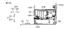
左後側へ向かうメダルMの先には、シュート48の縦板48Aが存在し、このメダルMは、縦板48Aのガイド面48Bに接触して左前側へバウンドする。メダルMがバウンドした先には、リジェクト部38が存在し、このメダルM(否と識別されたメダルM)は、自重により、リジェクト部38の開口38Aへ向けて落下してリジェクト部38内に収納される(メダルM7を参照)。左右方向Xに沿う基準線L4とガイド面48Bとの平面視における交差角度γは、約16度に設定される。メダル計数装置24は、貸出装置2の装置本体10から前側Y1に引き出すことができ、引き出された状態のメダル計数装置24では、リジェクト部38にアクセスしてリジェクト部38内のメダルMを回収することができる(後述ずる図14A〜図14C参照)。
A vertical plate 48A of the chute 48 exists at the tip of the medal M toward the left rear side, and this medal M bounces to the left front side in contact with the guide surface 48B of the vertical plate 48A. At the point where the medal M bounces, there is a reject portion 38, and this medal M (the medal M identified as “no”) falls toward the opening 38A of the reject portion 38 by its own weight and enters the reject portion 38. Stored (see medal M7). The crossing angle γ in plan view between the reference line L4 along the left-right direction X and the guide surface 48B is set to about 16 degrees. The medal counting device 24 can be pulled out from the device main body 10 of the lending device 2 to the front side Y1, and the medal counting device 24 in the pulled out state accesses the reject unit 38 and collects the medal M in the reject unit 38. (See FIGS. 14A to 14C described later).
このように、メダル計数装置24では、計数後に正と識別されたメダルMは、通常処理として排出口42から排出され、計数後に否と識別されたメダルMは、リジェクト処理としてリジェクト部38にリジェクトされる。この際、振分部37は、搬送路34内で搬送されるメダルMを排出口42またはリジェクト部38に振り分ける。計数部35によるメダルMの計数結果から、リジェクトされたメダルMの数だけ減算されてもよい。もちろん、遊技施設の方針により、減算されなくてもよい。
In this way, in the medal counting device 24, the medal M identified as positive after counting is discharged from the discharge port 42 as a normal process, and the medal M identified as not after counting is rejected to the reject unit 38 as a reject process. Is done. At this time, the sorting unit 37 sorts the medals M transported in the transport path 34 to the discharge port 42 or the reject unit 38. The number of medals M rejected may be subtracted from the result of counting medals M by the counting unit 35. Of course, it may not be subtracted according to the game facility policy.
メダルMを搬送するペースが1秒間で最大15枚であることから、搬送路34におけるメダルMの搬送速度は比較的高い。この場合、否と識別されたメダルMに振分部37の先端部37Aを接触させてメダルMの進行方向を変更する際に時間がかかると、このメダルMに後続のメダルMが衝突して、搬送路34内でメダルMが詰まってしまう。かと言って、メダルMを搬送するペースを落とすと、メダル計数装置24における処理速度が低下してしまう。
Since the medals M are transported at a maximum pace of 15 per second, the transport speed of the medals M on the transport path 34 is relatively high. In this case, if it takes time to change the advancing direction of the medal M by bringing the tip 37A of the sorting unit 37 into contact with the medal M identified as “no”, the subsequent medal M collides with the medal M. The medal M is jammed in the transport path 34. However, if the pace at which the medals M are transported is reduced, the processing speed in the medal counting device 24 is reduced.
そこで、振分部37は、搬送路34内で搬送されるメダルMをリジェクト部38に振り分ける場合には、平面視において、メダルMの進行方向である傾斜方向Pに対してリジェクト部38とは反対側へ角度βだけ傾斜した方向を向いた状態で当該メダルMに接触する。これにより、当該メダルMを失速させずに、その進行方向を確実に変更して当該メダルMをリジェクト部38に振り分けることができる。また、傾斜方向Pに対して傾斜した方向を向いた状態の振分部37に接触されたメダルMは、傾斜方向Pを向いた状態の振分部37に正面衝突される場合に比べて、振分部37との接触後の早い段階で搬送路34から外れてリジェクト部38に向かうことができる。
Therefore, when the allocating unit 37 distributes the medals M transported in the transport path 34 to the reject unit 38, the reject unit 38 is defined with respect to the inclination direction P that is the traveling direction of the medals M in plan view. The medal M is contacted in a state in which the direction is inclined to the opposite side by an angle β. Thus, the medal M can be distributed to the reject unit 38 by reliably changing the traveling direction without stalling the medal M. In addition, the medal M that is in contact with the sorting unit 37 in the state of being inclined with respect to the tilting direction P is front-collised with the sorting unit 37 in the state of facing the tilting direction P. At an early stage after the contact with the distribution unit 37, it can be removed from the conveyance path 34 and directed to the rejection unit 38.
特に、前述した約30度という浅い当たり角度βでメダルMに振分部37の先端部37Aを接触させることによって、高速で搬送されるメダルMを失速させることなく、その進行方向を搬送路34の左外側へ向けて一瞬で変更することができる。また、振分部37は、待機位置にあるときには搬送路34におけるメダルMの搬送方向における下流側に傾いていて、待機位置へ向かう際には上流側へ起立する(図4参照)。この構成であれば、振分部37が、高速で搬送されるメダルMに応答して、このメダルMの進行方向をリジェクト部38へと機敏に変更することができる。
In particular, by bringing the tip 37A of the allocating portion 37 into contact with the medal M at the shallow hitting angle β of about 30 degrees as described above, the medal M conveyed at high speed can be moved in the transport direction 34 without stalling. It can be changed in an instant toward the left outside. Further, the distribution unit 37 is inclined to the downstream side in the conveyance direction of the medal M in the conveyance path 34 when in the standby position, and rises to the upstream side when going to the standby position (see FIG. 4). If it is this structure, the distribution part 37 can change the advancing direction of this medal M to the rejection part 38 in response to the medal M conveyed at high speed.
よって、搬送路34では、振分部37に接触されたメダルMと後続のメダルMとの接触に起因したメダルMの詰りを抑制できる。また、メダルMを早いペースで次々に搬送できるので、メダル計数装置24における処理速度の向上を図れる。
Therefore, in the conveyance path 34, the clogging of the medal M caused by the contact between the medal M that is in contact with the sorting unit 37 and the subsequent medal M can be suppressed. Further, since the medals M can be conveyed one after another at a fast pace, the processing speed in the medal counting device 24 can be improved.
さらに、シュート48のガイド面48Bは、進行方向が変更されたメダルMに対して、前述した約16度という当たり角度γで接触する。これにより、ガイド面48Bに接触したメダルMを、搬送路34側へ戻すことなく、リジェクト部38に向けて正確にバウンドさせることができる。また、この角度γでシュート48を配置することにより、シュート48がメダル計数装置24において後側Y2へはみ出すことを極力抑えて、前後方向Yにおけるメダル計数装置24の小型化を図ることができる。
Further, the guide surface 48B of the chute 48 contacts the medal M whose traveling direction has been changed at the aforementioned hit angle γ of about 16 degrees. Thereby, the medal M that has contacted the guide surface 48B can be bound accurately toward the reject unit 38 without returning to the transport path 34 side. Further, by arranging the chute 48 at this angle γ, the medal counting device 24 in the front-rear direction Y can be reduced in size by preventing the chute 48 from protruding to the rear side Y2 in the medal counting device 24 as much as possible.
前述したように、メダルMの搬送路34は、平面視において、メダル計数装置24の奥行き方向である前後方向Yに対して傾斜する傾斜方向Pに沿って排出口42へ向けて延びている。そのため、メダル計数装置24の左右方向Xの寸法を従来製品と同じ寸法に抑えつつ、搬送路34を、前後方向Yに沿って延びる場合に比べて長く確保できる。また、搬送路34が傾斜方向Pに沿って延びる構成では、搬送路34における排出口42側の後端部34Bがメダル計数装置24内で右側X2に偏って配置される。そのため、メダル計数装置24では、後端部34Bに隣接する左側X1の領域にスペースを確保し、このスペースを利用してリジェクト部38を配置できる。以上の結果、メダル計数装置24では、省スペース化を図りつつメダルMの搬送路34を長く確保できる。
As described above, the transport path 34 of the medal M extends toward the discharge port 42 along the inclination direction P that is inclined with respect to the front-rear direction Y that is the depth direction of the medal counting device 24 in a plan view. Therefore, the conveyance path 34 can be ensured longer than the case where the medal counting device 24 extends along the front-rear direction Y while suppressing the dimension in the left-right direction X of the medal counting device 24 to the same dimension as the conventional product. Further, in the configuration in which the transport path 34 extends along the inclination direction P, the rear end portion 34B on the discharge port 42 side in the transport path 34 is arranged in the medal counting device 24 so as to be biased to the right side X2. Therefore, in the medal counting device 24, a space can be secured in the region of the left side X1 adjacent to the rear end portion 34B, and the reject portion 38 can be arranged using this space. As a result, the medal counting device 24 can secure a long medal M transport path 34 while saving space.
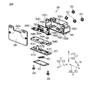
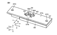
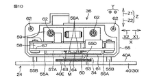
次に、識別部36の詳細について、メダル計数装置24に組み込まれた状態での識別部36の姿勢を基準として説明する。図8は、後側Y2から見たときにおける識別部36の分解斜視図である。図9は、識別部36の要部を下側Z2から見た斜視図である。図10は、メダル計数装置24に組み込まれた状態における識別部36の縦断面後側面図である。
Next, details of the identification unit 36 will be described with reference to the posture of the identification unit 36 in a state of being incorporated in the medal counting device 24. FIG. 8 is an exploded perspective view of the identification unit 36 when viewed from the rear side Y2. FIG. 9 is a perspective view of the main part of the identification unit 36 as viewed from the lower side Z2. FIG. 10 is a longitudinal sectional rear side view of the identification unit 36 in a state of being incorporated in the medal counting device 24.
図8を参照して、識別部36は、ケース55と、カバー56と、基板57と、スペーサ58と、ブラケット59と、拡散シート60と、クリアパネル61とを含む。
Referring to FIG. 8, identification unit 36 includes a case 55, a cover 56, a substrate 57, a spacer 58, a bracket 59, a diffusion sheet 60, and a clear panel 61.
ケース55は、左右方向Xに細長いボックス形状であり、その内部空間は、後側Y2へ開放されている。ケース55の下壁には、上側Z1へ突出しつつ前後方向Yに延びる2つのリブ55Aが左右方向Xに並んで設けられている。ケース55の下壁には、下側Z2へ突出する複数(ここでは4つ)の脚部55Bが前後左右に離れて配置されている。ケース55の後側面の上端部における左右の端部には、ケース55を前後方向Yに貫通する貫通穴55Cが1つずつ形成されている。ケース55の下壁において2つのリブ55Aの間の領域には、窓55Dが形成されている。窓55Dは、ケース55の下壁を上下方向Zに貫通する貫通穴であり、平面視において第2直交方向Qに長手の長方形状に形成されている。
The case 55 has a box shape elongated in the left-right direction X, and its internal space is open to the rear side Y2. On the lower wall of the case 55, two ribs 55A extending in the front-rear direction Y while projecting to the upper side Z1 are provided side by side in the left-right direction X. On the lower wall of the case 55, a plurality (four in this case) of leg portions 55B protruding to the lower side Z2 are disposed apart from each other in the front-rear and left-right directions. At the left and right ends of the upper end of the rear side surface of the case 55, one through hole 55C that penetrates the case 55 in the front-rear direction Y is formed. A window 55D is formed in a region between the two ribs 55A on the lower wall of the case 55. The window 55D is a through hole that penetrates the lower wall of the case 55 in the up-down direction Z, and is formed in a rectangular shape that is long in the second orthogonal direction Q in plan view.
カバー56は、前後方向Yから見て左右方向Xに長手の長方形状であり、前後方向Yに薄い板状に形成されている。カバー56の左右方向Xにおける両端部には、ねじ穴56Aが1つずつ形成されている。カバー56は、ケース55の内部空間を後側Y2から塞ぐように、ケース55に取り付けられる。ねじ62がケース55の貫通穴55Cに挿通されてねじ穴56Aに組みつけられることによって、ケース55とカバー56とが一体化される。
The cover 56 has a rectangular shape that is long in the left-right direction X when viewed from the front-rear direction Y, and is formed in a thin plate shape in the front-rear direction Y. One screw hole 56 </ b> A is formed at each end of the cover 56 in the left-right direction X. The cover 56 is attached to the case 55 so as to close the internal space of the case 55 from the rear side Y2. The case 55 and the cover 56 are integrated by inserting the screw 62 into the through hole 55C of the case 55 and assembling the screw 62 into the screw hole 56A.
基板57は、上下方向Zに薄く左右方向Xに長手の板状である。図9を参照して、基板57の下面57Aにおいて左右方向Xにおける中央部には、発光部63および受光部64が実装されている。発光部63は、たとえば白色光を発生するLEDで構成され、第2直交方向Qにおける受光部64の両側に1つずつ設けられている。そのため、これらの発光部63および受光部64は、第2直交方向Qに並んで配置されている。基板57において両側の発光部63のそれぞれと受光部64との間の領域には、基板57を上下方向Zに貫通する挿通穴57Bが形成されている。基板57の左右方向Xにおける両端部には、基板57を上下方向Zに貫通する貫通穴57Cが形成されている。
The substrate 57 has a plate shape that is thin in the vertical direction Z and long in the left-right direction X. Referring to FIG. 9, light emitting portion 63 and light receiving portion 64 are mounted at the center portion in the left-right direction X on lower surface 57 </ b> A of substrate 57. The light emitting unit 63 is configured by an LED that generates white light, for example, and is provided on each side of the light receiving unit 64 in the second orthogonal direction Q. Therefore, the light emitting unit 63 and the light receiving unit 64 are arranged side by side in the second orthogonal direction Q. An insertion hole 57 </ b> B that penetrates the substrate 57 in the vertical direction Z is formed in a region between each of the light emitting units 63 on both sides of the substrate 57 and the light receiving unit 64. At both ends in the left-right direction X of the substrate 57, through holes 57C that penetrate the substrate 57 in the up-down direction Z are formed.
スペーサ58は、上下方向Zに薄く左右方向Xに長手の板状である。スペーサ58の下面において左右方向Xにおける中央部には、下側Z2へ突出する2つのセパレータ58Aが左右方向Xに間隔を隔てて設けられている。セパレータ58Aは、左右方向Xに薄い板状である。スペーサ58の左右方向Xにおける両端部には、スペーサ58を上下方向Zに貫通する貫通穴58Bが形成されている(図8参照)。図9に示すようにスペーサ58を基板57に載せると、セパレータ58Aが基板57の挿通穴57Bに対して上側Z1から1つずつ挿通され、基板57の下面57Aから下側Z2に突出する。セパレータ58Aは、受光部64と、その両側の発光部63のそれぞれとの間に配置されて、隣り合う受光部64と発光部63との間を遮断している。
The spacer 58 has a plate shape that is thin in the vertical direction Z and long in the left-right direction X. Two separators 58A projecting downward Z2 are provided at intervals in the left-right direction X at the center in the left-right direction X on the lower surface of the spacer 58. The separator 58A has a thin plate shape in the left-right direction X. At both ends in the left-right direction X of the spacer 58, through holes 58B that penetrate the spacer 58 in the up-down direction Z are formed (see FIG. 8). As shown in FIG. 9, when the spacers 58 are placed on the substrate 57, the separators 58A are inserted into the insertion holes 57B of the substrate 57 one by one from the upper side Z1, and project from the lower surface 57A of the substrate 57 to the lower side Z2. The separator 58 </ b> A is disposed between the light receiving unit 64 and the light emitting units 63 on both sides of the light receiving unit 64, and blocks between the adjacent light receiving unit 64 and the light emitting unit 63.
図8を参照して、ブラケット59は、上下方向Zに薄く左右方向Xに長手の板状の横板59Aと、前後方向Yに薄く左右方向Xに長手の板状の縦板59Bとを一体的に含み、左右方向Xから見て略L字状に形成されている。横板59Aの左右方向Xにおける両端部には、ねじ穴59Cが形成され、縦板59Bの左右方向Xにおける両端部には、ねじ穴59Dが形成されている。
Referring to FIG. 8, a bracket 59 is formed by integrating a plate-like horizontal plate 59A that is thin in the vertical direction Z and long in the left-right direction X and a plate-like vertical plate 59B that is thin in the front-rear direction Y and long in the left-right direction X. In addition, it is substantially L-shaped when viewed from the left-right direction X. Screw holes 59C are formed at both ends in the left-right direction X of the horizontal plate 59A, and screw holes 59D are formed at both ends in the left-right direction X of the vertical plate 59B.
ねじ65が、基板57の貫通穴57Cおよびスペーサ58の貫通穴58Bに対して下側Z2から順に挿通され、ブラケット59の横板59Aのねじ穴59Cに組みつけられている。これによって、基板57とスペーサ58とブラケット59とが一体化されている。一体化された基板57、スペーサ58およびブラケット59は、ケース55内に収容されている。ケース55に取り付けられたねじ62がブラケット59の縦板59Bのねじ穴59Dに組みつけられることによって、ブラケット59がケース55に固定されている。図10に示すように、ケース55の下壁におけるリブ55Aが基板57に下側Z2から接触している。これにより、基板57は、ケース55内において基板57の下壁から少し浮いた状態で位置決めされている。基板57の下面57Aの発光部63および受光部64は、平面視においてケース55の下壁の窓55Dと重なっている。
Screws 65 are inserted through the through hole 57C of the substrate 57 and the through hole 58B of the spacer 58 in order from the lower side Z2, and are assembled to the screw holes 59C of the horizontal plate 59A of the bracket 59. Thus, the substrate 57, the spacer 58, and the bracket 59 are integrated. The integrated substrate 57, spacer 58, and bracket 59 are accommodated in the case 55. The bracket 59 is fixed to the case 55 by assembling the screw 62 attached to the case 55 into the screw hole 59D of the vertical plate 59B of the bracket 59. As shown in FIG. 10, the rib 55A on the lower wall of the case 55 is in contact with the substrate 57 from the lower side Z2. As a result, the substrate 57 is positioned in the case 55 in a state where it slightly floats from the lower wall of the substrate 57. The light emitting portion 63 and the light receiving portion 64 on the lower surface 57A of the substrate 57 overlap the window 55D on the lower wall of the case 55 in plan view.
拡散シート60は、発光部63からの光を拡散させるための白いシートであって、ケース55内において発光部63の真下に配置されている。クリアパネル61は、たとえば樹脂製であり、上下方向Zに薄い透明のパネルであって、ケース55内において拡散シート60よりも下側Z2に配置され、窓55Dに対して上側Z1から対向配置されている。左右方向Xにおける拡散シート60の両側に、ケース55の下壁のリブ55Aが位置している。
The diffusion sheet 60 is a white sheet for diffusing light from the light emitting unit 63, and is disposed in the case 55 just below the light emitting unit 63. The clear panel 61 is made of, for example, resin, and is a transparent panel that is thin in the vertical direction Z. The clear panel 61 is disposed on the lower side Z2 of the diffusion sheet 60 in the case 55, and is opposed to the window 55D from the upper side Z1. ing. On both sides of the diffusion sheet 60 in the left-right direction X, ribs 55A on the lower wall of the case 55 are located.
完成した識別部36がメダル計数装置24に取り付けられた状態では、ケース55の脚部55Bが、ベース部30の上壁40の上面40Aに上側Z1から連結されている。脚部55Bは、上面40Aにおいて搬送路34から外れた位置に配置されている。識別部36は、前述した支持フレーム50(図7参照)に締結部材によって固定されている。基板57の下面57Aの発光部63および受光部64は、クリアパネル61およびケース55の下壁の窓55Dを介して、搬送路34を上側Z1から臨んでいる。厳密には、それぞれの発光部63は、拡散シート60、クリアパネル61および窓55Dを順に介して、搬送路34を上側Z1から臨んでいる。
In a state where the completed identification unit 36 is attached to the medal counting device 24, the leg portion 55B of the case 55 is connected to the upper surface 40A of the upper wall 40 of the base portion 30 from the upper side Z1. The leg portion 55B is disposed at a position off the transport path 34 on the upper surface 40A. The identification unit 36 is fixed to the support frame 50 (see FIG. 7) described above by a fastening member. The light emitting part 63 and the light receiving part 64 on the lower surface 57A of the substrate 57 face the transport path 34 from the upper side Z1 through the clear panel 61 and the window 55D on the lower wall of the case 55. Strictly speaking, each light emitting unit 63 faces the conveyance path 34 from the upper side Z1 through the diffusion sheet 60, the clear panel 61, and the window 55D in this order.
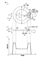
搬送路34内のメダルMが識別部36の真下を通過し始めたときの状態が、図11(a)に示されている。識別部36における発光部63および受光部64のまとまりは、第2直交方向Qにおいて、メダルMの直径Dよりも狭い範囲に収まるように配置されている。特に、図11(a)に示すバイメダルMを識別する場合には、発光部63および受光部64のまとまりは、円周心側の内側部分MAの直径dよりも狭い範囲に収まるように配置されることが好ましい。識別部36が識別できる範囲であるセンシングエリアAは、平面視において両側2つの発光部63と受光部64とを取り囲む略楕円状の比較的狭い領域である。
FIG. 11A shows a state when the medal M in the transport path 34 starts to pass directly under the identification unit 36. A group of the light emitting unit 63 and the light receiving unit 64 in the identification unit 36 is arranged so as to be within a narrower range than the diameter D of the medal M in the second orthogonal direction Q. In particular, when the bi-medal M shown in FIG. 11A is identified, the group of the light emitting unit 63 and the light receiving unit 64 is arranged to be within a range narrower than the diameter d of the inner portion MA on the circumferential center side. It is preferable. The sensing area A, which is a range that can be identified by the identifying unit 36, is a relatively narrow area of a substantially elliptical shape that surrounds the two light emitting units 63 and the light receiving unit 64 on both sides in plan view.
制御部39は、メダルMの計数のために投出部32の回転を開始させると、識別部36も作動させる。これにより、発光部63の発光が開始される。発光部63と受光部64との間は、セパレータ58Aによって遮断されているので、発光部63からの白色光が受光部64によって直接受けられることを抑制できる。
When the control unit 39 starts the rotation of the throwing-out unit 32 for counting the medals M, the identification unit 36 is also operated. Thereby, the light emission of the light emission part 63 is started. Since the space between the light emitting unit 63 and the light receiving unit 64 is blocked by the separator 58A, it is possible to prevent white light from the light emitting unit 63 from being directly received by the light receiving unit 64.
投出部32の回転に伴って搬送路34に投出されたメダルMが識別部36の真下に来ると、このメダルMでは、傾斜方向Pに沿う進行方向(白抜き矢印参照)における先頭側の部分が、平面視においてセンシングエリアAと重なってくる。これにより、それぞれの発光部63がメダルMへ向けて発光している状態となる。そのため、発光部63からの白色光は、拡散シート60およびクリアパネル61を順に通った後に、上側Z1からメダルMに照射される。拡散シート60により、発光部63から出たときはスポット光だった白色光が拡散される。これにより、それぞれの発光部63の白色光は、メダルMにおいてセンシングエリアAと重なっている部分の全域にわたって照射される。
When the medal M thrown onto the conveyance path 34 with the rotation of the throwing unit 32 comes directly below the identification unit 36, the medal M has a leading side in the traveling direction along the inclination direction P (see the white arrow). This part overlaps the sensing area A in plan view. As a result, each of the light emitting units 63 emits light toward the medal M. For this reason, the white light from the light emitting unit 63 passes through the diffusion sheet 60 and the clear panel 61 in order, and then irradiates the medal M from the upper side Z1. The diffusion sheet 60 diffuses white light that is spot light when it exits the light emitting unit 63. Thereby, the white light of each light emission part 63 is irradiated over the whole region of the medal M that overlaps the sensing area A.
メダルMの表面で反射した光は、受光部64によって受けられる。受光部64は、メダルMで反射した光の別々の波長域に感応する複数の感応部66を含む。ここでの波長域は、いわゆる光の三原色に応じて赤(R)、緑(G)および青(B)の3つ存在し、受光部64は、感応部66がこれらの波長域に感応することよって、メダルMでの反射光を赤、緑および青の成分別に検出し、これらの成分の割合に応じてメダルMの色を識別する。感応部66は、赤、緑および青に応じて3つ存在する。3つの感応部66は、青の波長域に感応して光の青の成分を検出する感応部66Bと、赤の波長域に感応して光の赤の成分を検出する感応部66Rと、緑の波長域に感応して光の緑の成分を検出する感応部66Gとに区別される。
The light reflected by the surface of the medal M is received by the light receiving unit 64. The light receiving unit 64 includes a plurality of sensitive units 66 that are sensitive to different wavelength ranges of light reflected by the medal M. Here, there are three wavelength ranges of red (R), green (G), and blue (B) according to the so-called three primary colors of light, and the light receiving unit 64 is sensitive to these wavelength ranges. Accordingly, the reflected light from the medal M is detected for each of the red, green, and blue components, and the color of the medal M is identified according to the ratio of these components. There are three sensitive parts 66 corresponding to red, green and blue. The three sensitive units 66 are a sensitive unit 66B that detects the blue component of light in response to the blue wavelength range, a sensitive unit 66R that detects the red component of light in response to the red wavelength range, and a green component. It is distinguished from the sensitive portion 66G that detects the green component of light in response to the wavelength region of.
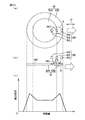
図11(c)は、バイメダルMが識別部36のセンシングエリアAを通過したときに感応部66が検出した反射光の光量(反射光量)の波形を示している。図11(c)のグラフでは、横軸がメダルMの移動量を示し、縦軸が反射光量を示している。それぞれの感応部66が対応する波長域に感応することによって出力した電圧を等時間間隔でサンプリングすると、図11(c)に示すような反射光量の波形が、赤、緑および青の成分毎に得られる。図11(c)は、感応部66Bが検出した青の成分についての反射光量の波形を示している。青色についての光の反射率は、バイメダルMにおける銀色の外周部分MBよりも金色の内側部分MAにおいて低いので、図11(c)の波形では、外周部分MBよりも内側部分MAにおいて反射光量が下がるように、内側部分MAと外周部分MBとで反射光量のレベルの差があらわれている。
FIG. 11C shows a waveform of the amount of reflected light (the amount of reflected light) detected by the sensitive unit 66 when the bi-medal M passes through the sensing area A of the identifying unit 36. In the graph of FIG. 11C, the horizontal axis indicates the amount of movement of the medal M, and the vertical axis indicates the amount of reflected light. When the voltage output by sensing each sensitive part 66 in the corresponding wavelength range is sampled at equal time intervals, the reflected light amount waveform as shown in FIG. 11C is obtained for each of the red, green and blue components. can get. FIG. 11C shows the waveform of the reflected light amount for the blue component detected by the sensitive unit 66B. Since the light reflectance for blue is lower in the gold inner portion MA than in the silver outer peripheral portion MB in the bi-medal M, in the waveform of FIG. 11C, the amount of reflected light is lower in the inner portion MA than in the outer peripheral portion MB. Thus, the difference in the level of the reflected light amount appears between the inner part MA and the outer peripheral part MB.
なお、搬送路34が設けられるベース部30の上壁40の上面40Aにおいて、センシングエリアAに一致する部分には、平面視においてセンシングエリアAよりも大きくメダルMよりも小さい穴40Eが形成されている(図5および図10参照)。これにより、メダルMがセンシングエリアAと重なっていない待機状態では、発光部63からの光は穴40Eに入り込むことにより反射しにくくなるので、反射光量を比較的低くしておける。このように待機状態の反射光量を低くしておくことにより、メダルMが識別部36の真下に来てセンシングエリアAと重なったときには反射光量を大幅に増大させることができる。これにより、受光部64において反射光の受ける感度を高めることができる。
Note that a hole 40E that is larger than the sensing area A and smaller than the medal M in plan view is formed on the upper surface 40A of the upper wall 40 of the base portion 30 where the transport path 34 is provided, in a portion that coincides with the sensing area A. (See FIGS. 5 and 10). Thereby, in the standby state where the medal M does not overlap the sensing area A, the light from the light emitting portion 63 is less likely to be reflected by entering the hole 40E, so that the amount of reflected light can be kept relatively low. By reducing the amount of reflected light in the standby state in this way, the amount of reflected light can be greatly increased when the medal M comes directly under the identification unit 36 and overlaps the sensing area A. Thereby, the sensitivity which reflected light in the light-receiving part 64 receives can be raised.
図11(a)を参照して、受光部64に含まれる複数の感応部66は、メダルMの進行方向(白抜き矢印参照)に直交する第2直交方向Qに並んで配置されている。これにより、それぞれの感応部66がメダルMからの反射光の波長域に感応するタイミングを極力一致させることができる。
Referring to FIG. 11A, the plurality of sensitive units 66 included in the light receiving unit 64 are arranged side by side in a second orthogonal direction Q that is orthogonal to the traveling direction of the medal M (see the white arrow). As a result, the timing at which each of the sensitive units 66 senses the wavelength range of the reflected light from the medal M can be matched as much as possible.
具体的には、メダルMの端や、バイメダルMの場合における内側部分MAと外周部分MBとの境界MCをそれぞれの感応部66が通過するタイミングを合わせることができる。これにより、それぞれの感応部66がメダルMの端や境界MCを通過する際に出力が変化するタイミングも合うので、赤、緑および青のそれぞれの反射光量の波形をメダルMの端や境界MCにおいてほぼ同時に変化させることができる。そのため、メダルMの端や境界MCにおける赤、緑および青の成分(スペクトル)の割合の関係がタイミングの誤差によって崩れることを抑制できる。つまり、受光部64では、複数の感応部66の間における感応のタイミングのずれによる誤差を低減できるので、識別部36は、どのメダルMであっても色を正しく識別することによって、メダルMの正否を正確に識別できる。
Specifically, the timing at which each sensitive portion 66 passes through the edge of the medal M or the boundary MC between the inner portion MA and the outer peripheral portion MB in the case of the buy medal M can be matched. As a result, the timing at which the output changes when each sensitive unit 66 passes the edge or boundary MC of the medal M matches, so the waveform of the reflected light amount of each of red, green, and blue is changed to the edge of the medal M or the boundary MC. At about the same time. Therefore, it is possible to suppress the relationship between the ratios of the red, green, and blue components (spectrums) at the edge of the medal M and the boundary MC from being broken due to a timing error. That is, the light receiving unit 64 can reduce an error due to a shift in sensitivity timing among the plurality of sensitive units 66. Therefore, the identifying unit 36 correctly identifies the color of any medal M, so The correctness can be accurately identified.
そして、識別部36に含まれる発光部63および受光部64は、前述したように、第2直交方向Qに並んで配置される。これにより、センシングエリアAが第2直交方向Qに沿って長手となる。バイメダルMの内側部分MAおよび外周部分MBのように、メダルMには、その進行方向である傾斜方向Pに沿って隣り合う複数の領域が存在する場合がある。センシングエリアAが第2直交方向Qに沿っていれば、これらの領域の境界は、第2直交方向Qに並んで配置された発光部63および受光部64のそれぞれをほぼ同じタイミングで通過できる。
The light emitting unit 63 and the light receiving unit 64 included in the identification unit 36 are arranged side by side in the second orthogonal direction Q as described above. As a result, the sensing area A is elongated along the second orthogonal direction Q. Like the inner portion MA and the outer peripheral portion MB of the buy medal M, the medal M may have a plurality of adjacent areas along the inclination direction P that is the traveling direction thereof. If the sensing area A is along the second orthogonal direction Q, the boundary between these regions can pass through the light emitting unit 63 and the light receiving unit 64 arranged side by side in the second orthogonal direction Q at substantially the same timing.
バイメダルMの場合には、バイメダルMの内側部分MAと外周部分MBとの境界MCがセンシングエリアAに差し掛かったときに、この境界MCは、発光部63および受光部64のそれぞれをほぼ同じタイミングで通過できる。この場合、センシングエリアAは、内側部分MAと外周部分MBとに跨った状態を極力早く終わらせて、境界MCから早く外れることができる。これにより、発光部63からの白色光が内側部分MAと外周部分MBとに跨って照射されにくいので、内側部分MAでの反射光と外周部分MBでの反射光とが混ざった状態で受光部64に受けられることを極力抑制できる。また、境界MCについての発光部63での発光のタイミングと受光部64での受光のタイミングとを極力一致させることができる。そのため、図11(c)の波形では、内側部分MAと外周部分MBとの境界MCで反射光量が急激に変化するので、内側部分MAと外周部分MBとで反射光量のレベルの差が明確になる。そのため、識別部36は、この境界MCを正確に認識できるとともに、バイメダルMにおける複数の色を正しく識別できるので、メダルMの正否を効果的に識別できる。
In the case of the bi-medal M, when the boundary MC between the inner portion MA and the outer peripheral portion MB of the bi-medal M reaches the sensing area A, the boundary MC causes each of the light emitting unit 63 and the light receiving unit 64 to be at substantially the same timing. I can pass. In this case, the sensing area A can be quickly removed from the boundary MC by ending the state straddling the inner portion MA and the outer peripheral portion MB as soon as possible. Accordingly, since the white light from the light emitting unit 63 is difficult to be radiated across the inner part MA and the outer peripheral part MB, the light receiving part in a state where the reflected light from the inner part MA and the reflected light from the outer peripheral part MB are mixed. 64 can be suppressed as much as possible. Further, the timing of light emission at the light emitting unit 63 and the timing of light reception at the light receiving unit 64 for the boundary MC can be matched as much as possible. Therefore, in the waveform of FIG. 11 (c), the amount of reflected light changes abruptly at the boundary MC between the inner portion MA and the outer peripheral portion MB, so that the difference in level of the reflected light amount between the inner portion MA and the outer peripheral portion MB is clear. Become. Therefore, the identification unit 36 can accurately recognize the boundary MC and can correctly identify a plurality of colors in the buy medal M, so that the correctness of the medal M can be effectively identified.
ちなみに、比較例である図12(a)および(b)に示すように、発光部63および受光部64が第2直交方向Qでなく進行方向(傾斜方向P)に並んで配置される場合には、センシングエリアAが傾斜方向Pに沿って長手となる。この場合、境界MCがセンシングエリアAを通過する際に、センシングエリアAが内側部分MAと外周部分MBとに跨った状態が長引いてしまう。これにより、発光部63からの白色光が比較的長時間にわたって内側部分MAと外周部分MBとに跨って照射されるので、内側部分MAでの反射光と外周部分MBでの反射光とが混ざった状態で受光部64に受けられる。これでは、図12(c)に示すように、反射光量の波形では、境界MCで反射光量の変化が緩やかになるので、内側部分MAと外周部分MBとでの反射光量のレベルの差が曖昧になる。そのため、比較例の場合には、識別部36がバイメダルMの色を正しく識別することが困難である。
Incidentally, when the light emitting part 63 and the light receiving part 64 are arranged side by side in the traveling direction (inclination direction P) instead of the second orthogonal direction Q as shown in FIGS. 12A and 12B which are comparative examples. , The sensing area A is elongated along the tilt direction P. In this case, when the boundary MC passes the sensing area A, the state where the sensing area A straddles the inner portion MA and the outer peripheral portion MB is prolonged. Thereby, since the white light from the light emitting part 63 is irradiated over the inner part MA and the outer peripheral part MB for a relatively long time, the reflected light from the inner part MA and the reflected light from the outer peripheral part MB are mixed. It is received by the light receiving unit 64 in the state. In this case, as shown in FIG. 12C, in the waveform of the reflected light amount, the change in the reflected light amount becomes moderate at the boundary MC, so that the difference in the level of the reflected light amount between the inner portion MA and the outer peripheral portion MB is ambiguous. become. Therefore, in the case of the comparative example, it is difficult for the identification unit 36 to correctly identify the color of the buy medal M.
また、本実施形態では、図11(a)に示すように発光部63が第2直交方向Qにおける受光部64の両側に設けられることにより、受光部64は、発光部63の発光によりメダルMで反射した光を効果的に受けることができる。発光部63および受光部64のまとまりは、第2直交方向Qにおいて、メダルMの直径Dよりも狭い範囲に収まるように配置されるので、発光部63の発光により生じた光を効果的にメダルMで反射させて受光部64で受けることができる。そのため、識別部36は、メダルMの正否を正確に識別できる。
In this embodiment, as shown in FIG. 11A, the light emitting units 63 are provided on both sides of the light receiving unit 64 in the second orthogonal direction Q, so that the light receiving unit 64 emits the medal M by the light emission of the light emitting unit 63. The light reflected by can be received effectively. The group of the light emitting unit 63 and the light receiving unit 64 is arranged in a range narrower than the diameter D of the medal M in the second orthogonal direction Q, so that the light generated by the light emission of the light emitting unit 63 can be effectively used as the medal. The light can be reflected by M and received by the light receiving unit 64. Therefore, the identification unit 36 can accurately identify whether the medal M is correct or not.
このように発光部63および受光部64ならびに感応部66のレイアウトを工夫することによって、光軸を調整するレンズ等の高価な光学部品を用いない安価な構成であっても、センシングエリアAを限定して、単色のメダルMやバイメダルMを高精度に識別することができる。
Thus, by devising the layout of the light emitting unit 63, the light receiving unit 64, and the sensitive unit 66, the sensing area A is limited even in an inexpensive configuration that does not use expensive optical components such as a lens for adjusting the optical axis. Thus, the single-color medal M and the bi-medal M can be identified with high accuracy.
また、従来では色違いのメダルMの混入を従業員による監視に頼っていたが、このメダル計数装置24では、前述した安価な構成によって色違いのメダルMを識別し、リジェクト部38に自動的に振り分けることができる。
Further, in the past, the medals M of different colors depended on the monitoring by the employee. However, in the medal counting device 24, the medals M of different colors are identified by the above-described inexpensive configuration, and the rejection unit 38 automatically Can be sorted.
次に、メダル計数装置24で行われるメダルMについての全般的な処理(以下では、メダル処理と呼ぶことにする)について、図13のフローチャートを参照しながら説明する。メダル処理は、1枚または複数枚のメダルMが投入皿22に投入されてから、これら全てのメダルMが計数および識別された後にリジェクト部38および排出口42のどちらかに振り分けられ、メダルMの計数結果が出力されるまでの一連の処理である。メダル処理には、前述した通常処理やリジェクト処理が含まれる。
Next, general processing (hereinafter referred to as medal processing) for the medal M performed by the medal counting device 24 will be described with reference to the flowchart of FIG. In the medal processing, one or more medals M are inserted into the insertion tray 22, and after all the medals M are counted and identified, they are distributed to either the reject unit 38 or the discharge port 42. This is a series of processes until the counting result is output. The medal process includes the above-described normal process and reject process.
収納部31へのメダルMの投入があると(ステップS1でYES)、制御部39は、メダル処理を開始する。具体的に、制御部39は、駆動部33の駆動を開始し、投出部32を回転させる(ステップS2)。これにより、収納部31内のメダルMが投出部32によって1枚ずつ搬送路34内へ投出される。投出されて搬送路34内を搬送されるメダルMは、計数部35によって計数される(ステップS3)。計数された後に引き続き搬送路34内を搬送されるメダルMの種別は、識別部36によって識別される(ステップS4)。制御部39は、このメダルMが正のメダルであるとの識別に応じて(ステップS5でYES)、振分部37を待機位置で維持することによって、この正のメダルMを排出口42から回収通路52に排出する(ステップS6)。次に投入されたメダルMがあれば(ステップS7でYES)、制御部39は、ステップS2以降の処理を繰り返す。次のメダルMがなければ(ステップS7でNO)、制御部39は、駆動部33の駆動を停止して、今回のメダル処理で計数部35が計数したメダルMの総数を計数結果として出力し、島コントローラ80や管理装置90に送信する(ステップS8)。これにより、メダル計数装置24における今回の一連のメダル処理が終了する。
When the medal M is inserted into the storage unit 31 (YES in step S1), the control unit 39 starts medal processing. Specifically, the control unit 39 starts driving the drive unit 33 and rotates the throwing unit 32 (step S2). Accordingly, the medals M in the storage unit 31 are thrown out one by one by the throwing unit 32 into the transport path 34. The medals M that are thrown out and transported in the transport path 34 are counted by the counting unit 35 (step S3). The type of the medal M that is subsequently transported in the transport path 34 after being counted is identified by the identifying unit 36 (step S4). In response to the identification that the medal M is a positive medal (YES in step S5), the control unit 39 maintains the allocating unit 37 in the standby position, thereby removing the positive medal M from the discharge port 42. It discharges to the collection passage 52 (step S6). Next, if there is a medal M inserted (YES in step S7), the control unit 39 repeats the processes in and after step S2. If there is no next medal M (NO in step S7), the control unit 39 stops driving the drive unit 33 and outputs the total number of medals M counted by the counting unit 35 in the current medal process as a counting result. The data is transmitted to the island controller 80 and the management device 90 (step S8). Thus, the current series of medal processing in the medal counting device 24 is completed.
一方、制御部39は、否のメダルであると識別されたメダルMについては(ステップS5でNO)、振分部37を作動位置まで回動させることによって、この否のメダルMをリジェクト部38にリジェクトする(ステップS9)。このように、否のメダルMを通常はリジェクトすることにする運用を、第1運用と呼ぶことにする。逆に、否のメダルMを通常はリジェクトしないことにする第2運用があり、遊技施設の都合により、第1運用および第2運用のどちらかを選択できる。第1運用および第2運用の選択は、たとえば、従業員による貸出装置2の表示操作部15(図2参照)や管理装置90の操作部(図示せず)の操作によって実行される。第2運用の場合には、制御部39は、振分部37を待機位置で維持することによって、否のメダルMを排出口42から回収通路52に排出する(ステップS9)。このように、制御部39は、振分部37を作動位置または待機位置に切り換えることによって、リジェクト部38や排出口42という複数の送出先におけるいずれかの送出先へ否のメダルMを送り出す送出制御を行う。
On the other hand, for the medal M identified as a negative medal (NO in step S5), the control unit 39 rotates the sorting unit 37 to the operating position, thereby rejecting the negative medal M to the reject unit 38. (Step S9). The operation that normally rejects the medal M is referred to as the first operation. Conversely, there is a second operation in which the rejected medal M is not normally rejected, and either the first operation or the second operation can be selected depending on the convenience of the gaming facility. The selection of the first operation and the second operation is performed by, for example, an operation of a display operation unit 15 (see FIG. 2) of the lending device 2 or an operation unit (not shown) of the management device 90 by an employee. In the case of the second operation, the control unit 39 keeps the sorting unit 37 at the standby position, thereby discharging the rejected medal M from the discharge port 42 to the collection passage 52 (step S9). In this way, the control unit 39 switches the sorting unit 37 to the operating position or the standby position, thereby sending out a medal M that is rejected to any one of a plurality of destinations such as the reject unit 38 and the discharge port 42. Take control.
遊技媒体計数システム100では、否のメダルMの発生の度合が管理されている。否のメダルMの発生の度合を示す指標として、以下の指標(1)〜(4)が一例として挙げられる。
In the game medium counting system 100, the degree of occurrence of a negative medal M is managed. The following indices (1) to (4) are given as an example of the index indicating the degree of occurrence of the medal M.
指標(1)は、各貸出装置2のメダル計数装置24でのメダル処理において、計数部35が今まで計数したメダルMにおける否のメダルMの混入の度合であり、否のメダルMの実際の数(以下では、混入数と呼ぶ)であってもよいし、否のメダルMの混入率であってもいし、否のメダルMの混入が発生する頻度(以下では、混入発生頻度と呼ぶ)であってもよい。混入数は、識別部36が否のメダルMを識別した回数でもある。混入率は、計数部35が今まで計数したメダルMに占める否のメダルMの割合である。混入発生頻度は、たとえば、否のメダルMの混入が連続して発生した場合における混入の連続発生回数である。指標(1)の実際の値は、各貸出装置2のメダル計数装置24の制御部39のメモリ(図示せず)に記憶されたり、島コントローラ80や管理装置90に管理されたりする。
The index (1) is the degree of mixing of the negative medal M in the medal M counted by the counting unit 35 in the medal processing in the medal counting device 24 of each lending device 2. May be the number (hereinafter referred to as the number of mixing), or may be the mixing ratio of the negative medal M, or the frequency of occurrence of the mixing of the negative medal M (hereinafter referred to as the mixing occurrence frequency). It may be. The number of mixing is also the number of times that the identification unit 36 has identified the negative medal M. The mixing rate is a ratio of the medals M that are not included in the medals M counted so far by the counting unit 35. The mixing occurrence frequency is, for example, the number of continuous occurrences of mixing in the case where mixing of negative medals M occurs continuously. The actual value of the index (1) is stored in a memory (not shown) of the control unit 39 of the medal counting device 24 of each lending device 2, or is managed by the island controller 80 or the management device 90.
指標(2)は、それぞれの島において島内の全ての貸出装置2のメダル計数装置24によって所定期間内に計数したメダルMにおける否のメダルMの混入の度合であり、指標(1)と同様に、混入数であってもよし、混入率であってもよいし、混入発生頻度であってもよい。指標(2)の実際の値は、たとえば、島コントローラ80や管理装置90に管理されており、メダル計数装置24の制御部39は、島コントローラ80や管理装置90から指標(2)を取得する。
The index (2) is the degree of mixing of negative medals M in the medals M counted within a predetermined period by the medal counting devices 24 of all the lending devices 2 on the islands, as in the index (1). It may be the mixing number, the mixing rate, or the mixing occurrence frequency. The actual value of the index (2) is managed by, for example, the island controller 80 and the management device 90, and the control unit 39 of the medal counting device 24 acquires the index (2) from the island controller 80 and the management device 90. .
指標(3)は、遊技施設全体における貸出装置2のメダル計数装置24によって所定期間内に計数したメダルMにおける否のメダルMの混入の度合であり、指標(1)および(2)と同様に、混入数であってもよし、混入率であってもよいし、混入発生頻度であってもよい。指標(3)の実際の値は、たとえば、管理装置90に記憶されており、メダル計数装置24の制御部39は、管理装置90から指標(3)を取得する。
The index (3) is the degree of mixing of the negative medal M in the medal M counted within a predetermined period by the medal counting device 24 of the lending device 2 in the entire gaming facility, and is the same as the indexes (1) and (2). It may be the mixing number, the mixing rate, or the mixing occurrence frequency. The actual value of the index (3) is stored in, for example, the management device 90, and the control unit 39 of the medal counting device 24 acquires the index (3) from the management device 90.
指標(4)は、第1運用におけるリジェクト部38における収納状態である。リジェクト部38が空の状態から識別部36が否のメダルMを識別した回数の累積値や、否のメダルMをリジェクトするために振分部37が作動位置まで回動した回数の累積値は、リジェクト部38に収納された否のメダルMの枚数と一致する。これらの累積値のそれぞれがリジェクト部38の容量、つまり、リジェクト部38に収納できるメダルMの上限数に到達すると、リジェクト部38の収納状態は、メダルMが満杯になったフル状態にある。これらの累積値のそれぞれがリジェクト部38に収納できるメダルMの上限数の手前に到達すると、リジェクト部38の収納状態は、メダルMがほぼ満杯になったニアフル状態にある。なお、制御部39に接続された専用のセンサ(図示せず)を設けて、このセンサによって、リジェクト部38の収納状態を検知してもよい。指標(4)の実際の値は、各貸出装置2のメダル計数装置24の制御部39のメモリ(図示せず)に記憶されたり、島コントローラ80や管理装置90に管理されたりする。
The index (4) is the storage state in the reject unit 38 in the first operation. The cumulative value of the number of times that the discriminating unit 36 has identified the medals M that have been rejected from the state in which the reject unit 38 is empty, and the cumulative value of the number of times the allocating unit 37 has been rotated to the operating position in order to reject the medals M of no This matches the number of medals M that are not stored in the reject unit 38. When each of these accumulated values reaches the capacity of the reject unit 38, that is, the upper limit number of medals M that can be stored in the reject unit 38, the storage state of the reject unit 38 is in a full state where the medal M is full. When each of these accumulated values reaches the upper limit of the number of medals M that can be stored in the reject unit 38, the storage state of the reject unit 38 is in a near-full state in which the medals M are almost full. Note that a dedicated sensor (not shown) connected to the control unit 39 may be provided, and the storage state of the reject unit 38 may be detected by this sensor. The actual value of the index (4) is stored in a memory (not shown) of the control unit 39 of the medal counting device 24 of each lending device 2, or is managed by the island controller 80 or the management device 90.
以上の指標(1)〜(4)という否のメダルMの発生の度合のそれぞれには、遊技施設側によって任意の閾値が定められている。否のメダルMの発生の度合が増して閾値に到達すると、遊技施設では見過ごせない程度に否のメダルMが頻発していることになる。
Arbitrary thresholds are determined by the game facility side for the degree of occurrence of medals M, which are the above indices (1) to (4). When the degree of occurrence of the negative medal M increases and reaches the threshold value, the negative medal M frequently occurs to the extent that it cannot be overlooked at the gaming facility.
制御部39は、否のメダルと識別したメダルMを、第1運用のステップS9ではリジェクトし、第2運用のステップS9では排出した場合には、今回の否のメダルを含めた最新の否のメダルMの発生の度合が閾値に到達したか否かを確認する(ステップS10)。この際、制御部39は、前述した指標(1)〜(4)の全てまたは複数の指標についてステップS10の処理を実行してもよいし、前述した指標(1)〜(4)のいずれか1つの指標についてステップS10の処理を実行してもよい。以下では、指標(1)〜(4)のいずれか1つの指標についてステップS10の処理が実行されるものとする。
When the control unit 39 rejects the medal M identified as a negative medal in step S9 of the first operation and discharges it in the step S9 of the second operation, the control unit 39 determines the latest information including the current medal. It is confirmed whether or not the degree of occurrence of the medal M has reached the threshold (step S10). At this time, the control unit 39 may execute the process of step S10 for all or a plurality of indexes (1) to (4) described above, or any one of the indexes (1) to (4) described above. You may perform the process of step S10 about one parameter | index. In the following, it is assumed that the process of step S10 is executed for any one of the indices (1) to (4).
否のメダルMの発生の度合が閾値に到達していない場合(ステップS10でNO)、次に投入されたメダルMがあれば(ステップS7でYES)、制御部39は、ステップS2以降の処理を繰り返す。次のメダルMがなければ(ステップS7でNO)、制御部39は、駆動部33の駆動を停止して、今回の処理で計数部35が計数したメダルMの総数を計数結果として出力し、島コントローラ80や管理装置90に送信する(ステップS8)。これにより、今回の一連のメダル処理が終了する。なお、計数されたものの否と識別されたメダルMの数は、遊技施設の都合によって、計数結果に含まれてもよいし、計数結果から差し引かれてもよい。
If the degree of occurrence of the negative medal M has not reached the threshold value (NO in step S10), and if there is a medal M inserted next (YES in step S7), the control unit 39 performs the processes in and after step S2. repeat. If there is no next medal M (NO in step S7), the control unit 39 stops driving the driving unit 33 and outputs the total number of medals M counted by the counting unit 35 in the current process as a counting result. It transmits to the island controller 80 and the management device 90 (step S8). Thus, the current series of medal processing ends. Note that the number of medals M identified as being counted or not may be included in the counting result or subtracted from the counting result depending on the convenience of the gaming facility.
一方、否のメダルMの発生の度合が閾値に到達した場合(ステップS10でYES)、制御部39は、切換処理を実行する(ステップS11)。切換処理には、以下のパターン(1)〜(3)が一例として挙げられる。
On the other hand, when the degree of occurrence of the negative medal M reaches the threshold value (YES in step S10), the control unit 39 executes a switching process (step S11). Examples of the switching process include the following patterns (1) to (3).
パターン(1)の切換処理は、否のメダルMを通常はリジェクトする第1運用において実行される。パターン(1)の切換処理として、制御部39は、後続の正のメダルMを引き継き排出するものの、後続の否のメダルMを、リジェクトするのではなく、正のメダルMと同様に排出するようにしてから、ステップS1以降の処理を実行する。これにより、後続の否のメダルMは、ステップS9では、排出口42から回収通路52に排出される。このように正および否のいずれもメダルMも排出するという運用は、否のメダルMの発生の度合を減らす処置(たとえば、リジェクト部38からのメダルMの回収)が行われない限り、以降のメダル処理においても継続される。
The pattern (1) switching process is executed in the first operation in which the rejected medal M is normally rejected. As the pattern (1) switching process, the control unit 39 takes over the subsequent positive medal M and discharges it, but does not reject the subsequent negative medal M, but discharges it in the same manner as the positive medal M. Then, the processing after step S1 is executed. As a result, the succeeding medal M is discharged from the discharge port 42 to the collection passage 52 in step S9. The operation of discharging both positive and negative medals M in this way is performed unless a measure for reducing the degree of generation of negative medals M (for example, collection of medals M from the reject unit 38) is performed. It continues in medal processing.
パターン(2)の切換処理は、否のメダルMを通常は排出する第2運用において実行される。パターン(2)の切換処理として、制御部39は、後続の正のメダルMを引き継き排出するものの、後続の否のメダルMを、排出するのではなく、リジェクトするようにしてから、ステップS1以降の処理を実行する。これにより、後続の否のメダルMは、ステップS9では、リジェクト部38にリジェクトされる。第2運用では、通常のリジェクト部38は空になるように設定されていて、否のメダルMの発生の度合が閾値に到達した場合には、否のメダルMがリジェクト部38にリジェクトされる。
The pattern (2) switching process is executed in the second operation in which the rejected medal M is normally discharged. As the pattern (2) switching process, the control unit 39 takes over the subsequent positive medal M and discharges it, but rejects the subsequent negative medal M instead of discharging it. The processes after S1 are executed. Thereby, the medal M which is not succeeded is rejected by the reject unit 38 in step S9. In the second operation, the normal reject unit 38 is set to be empty, and the reject medal M is rejected by the reject unit 38 when the degree of occurrence of the reject medal M reaches the threshold value. .
このように、パターン(1)および(2)のいずれの切換処理においても、制御部39は、所定条件に応じて、否のメダルMの送出先がこれまでの送出制御とは異なる送出制御を行う。つまり、制御部39は、送出制御の変更に伴い、所定条件に応じて否のメダルMの送出先を切り換える。具体的には、パターン(1)の切換処理では、制御部39は、所定条件に応じて、振分部37を作動位置から待機位置に切り換ることによって、否のメダルMの送出先をリジェクト部38から排出口42に切り換える。パターン(2)の切換処理では、制御部39は、所定条件に応じて、振分部37を待機位置から作動位置に切り換ることによって、否のメダルMの送出先を排出口42からリジェクト部38に切り換える。
As described above, in any of the switching processes of the patterns (1) and (2), the control unit 39 performs the sending control in which the destination of the medal M is not different from the sending control so far according to the predetermined condition. Do. That is, the control unit 39 switches the destination of the rejected medal M according to the predetermined condition in accordance with the change of the sending control. Specifically, in the pattern (1) switching process, the control unit 39 switches the distribution unit 37 from the operating position to the standby position according to a predetermined condition, thereby determining the destination of the rejected medal M. The reject unit 38 is switched to the discharge port 42. In the pattern (2) switching process, the control unit 39 rejects the medal M delivery destination from the discharge port 42 by switching the sorting unit 37 from the standby position to the operating position in accordance with a predetermined condition. Switch to section 38.
ここでの所定条件は、指標(1)の場合には、計数部35が今まで計数したメダルMにおける否のメダルMの混入の度合である指標(1)が、閾値という所定の度合に到達することである。また、指標(2)の場合での所定条件は、それぞれの島における全ての貸出装置2のメダル計数装置24によって所定期間内に計数したメダルMにおける否のメダルMの混入の度合である指標(2)が、閾値という所定の度合に到達することである。また、指標(3)の場合での所定条件は、遊技施設全体における貸出装置2のメダル計数装置24によって所定期間内に計数したメダルMにおける否のメダルMの混入の度合である指標(3)が、閾値という所定の度合に到達することである。また、指標(4)の場合での所定条件は、リジェクト部38における否のメダルMの収納状態である指標(4)が、閾値に相当するフル状態やニアフル状態という所定状態に到達することである。
In the case of the index (1), the predetermined condition here is that the index (1), which is the degree of mixing of the negative medal M in the medal M counted up to now by the counting unit 35, reaches the predetermined degree of threshold. It is to be. In addition, the predetermined condition in the case of the index (2) is an index (degree of mixing of negative medals M in the medals M counted within a predetermined period by the medal counting devices 24 of all the lending devices 2 on each island ( 2) is to reach a predetermined degree of threshold. In addition, the predetermined condition in the case of the index (3) is the index (3) that is the degree of mixing of the negative medal M in the medal M counted within the predetermined period by the medal counting device 24 of the lending device 2 in the entire gaming facility. Is to reach a predetermined degree of threshold. In addition, the predetermined condition in the case of the index (4) is that the index (4) which is the storage state of the rejected medal M in the reject unit 38 reaches a predetermined state such as a full state or a near full state corresponding to the threshold value. is there.
パターン(3)の切換処理に関連して、管理装置90が、遊技施設全体における否のメダルMの発生の度合(ここでは、前述した指標(3))を管理していて、この度合についてのステップS10の処理をメダル計数装置24の制御部39の代わりに行う。否のメダルMの発生の度合が閾値に到達した場合(ステップS10でYES)、管理装置90は、各メダル計数装置24に、その旨を通知する。管理装置90からの通知を受信した各メダル計数装置24の制御部39は、切換処理として、識別部36が今後1枚でも否のメダルMを識別した場合にはメダル計数装置24をエラーダウンするようにしてから(ステップS11)、ステップS1以降の処理を実行する。これにより、各メダル計数装置24では、制御部39が管理装置90からの通知を受信した後に識別部36が1枚でも否のメダルMを識別した場合には(ステップS5でNO)、制御部39は、ステップS9の処理を無視して、振分部37を作動位置まで回動させて、この否のメダルMをリジェクト部38にリジェクトさせてから、自身のメダル計数装置24をエラーダウンして、その動作を停止させる。つまり、パターン(3)の場合、制御部39は、前述した所定条件が満たされた後に識別部36が否のメダルMを識別した場合に、メダル計数装置24をエラーダウンする。
In relation to the switching process of the pattern (3), the management device 90 manages the degree of occurrence of the negative medal M in the entire gaming facility (here, the index (3) described above). The process of step S10 is performed instead of the control unit 39 of the medal counting device 24. When the degree of occurrence of the negative medal M reaches the threshold value (YES in step S10), the management device 90 notifies each medal counting device 24 to that effect. The control unit 39 of each medal counting device 24 that has received the notification from the management device 90 lowers the error of the medal counting device 24 when the discriminating unit 36 identifies one or more medals M as a switching process. After doing so (step S11), the processing after step S1 is executed. Thereby, in each medal counting device 24, when the identification unit 36 identifies even one medal M after the control unit 39 receives the notification from the management device 90 (NO in step S5), the control unit 39 39, ignoring the process of step S9, rotating the allocating unit 37 to the operating position, rejecting the medal M of this rejection to the rejecting unit 38, and then reducing the error of the own medal counting device 24. To stop the operation. That is, in the case of pattern (3), the control unit 39 performs error-down of the medal counting device 24 when the identifying unit 36 identifies a negative medal M after the above-described predetermined condition is satisfied.
パターン(3)の切換処理は、パターン(1)やパターン(2)の切換処理と組みわされてもよい。この場合、パターン(1)またはパターン(2)の切換処理が実行された後にパターン(3)の切換処理が実行される。そのため、パターン(3)の切換処理が実行されると、制御部39は、その後に1枚でも否のメダルMを識別した場合には(ステップS5でNO)、第1運用および第2運用のいずれの場合でも、パターン(1)やパターン(2)の切換処理に応じたステップS9の処理を無視して、メダル計数装置24をエラーダウンする。このように、パターン(3)では、遊技媒体計数システム100の全体で否のメダルMの発生の度合を管理し、その度合が閾値に到達するほどに否のメダルMの発生頻度が高い場合には、その旨を各メダル計数装置24に通知して、以降で否のメダルMが発生したメダル計数装置24をエラーダウンさせて、否のメダルMの発生源を特定できるようにしている。
The pattern (3) switching process may be combined with the pattern (1) or pattern (2) switching process. In this case, after the pattern (1) or pattern (2) switching process is executed, the pattern (3) switching process is executed. Therefore, when the pattern (3) switching process is executed, if the control unit 39 subsequently identifies one or no medal M (NO in step S5), the control unit 39 performs the first operation and the second operation. In any case, the medal counting device 24 is reduced in error by ignoring the process of step S9 corresponding to the pattern (1) or pattern (2) switching process. As described above, in the pattern (3), the degree of occurrence of the negative medal M is managed in the entire game medium counting system 100, and the occurrence frequency of the negative medal M is so high that the degree reaches the threshold value. Notifies each medal counting device 24 to that effect and causes the medal counting device 24 in which a negative medal M has subsequently been generated to error down so that the source of the negative medal M can be identified.
次に、リジェクト部38から否のメダルMを回収する作業の手順について説明する。メダルMの回収は、メダル計数装置24がエラーダウンしたタイミングや、遊技施設の閉店後において従業員によって行われる。貸出装置2に組み込まれた状態におけるメダル計数装置24では、リジェクト部38は、図14Aに示すように、貸出装置2の後端側に位置している。貸出装置2は、台70の後寄りの領域に載置されており、貸出装置2の装置本体10の前面10Aの下部には、装置本体10内のメダル計数装置24に前側Y1からアクセスするための開口10Bが形成されている。台70の上面においてメダル計数装置24よりも前側Y1の領域には、灰皿等の固定物71が固定されている。メダル計数装置24を開口10Bから水平方向Hに沿って前側Y1へ引き出すと、メダル計数装置24の下部の前端が固定物71にぶつかってしまい、メダル計数装置24をそれ以上引き出すことができない虞がある。
Next, the procedure of the work of collecting the negative medal M from the reject unit 38 will be described. The collection of the medals M is performed by the employee at the timing when the medal counting device 24 is in an error-down state or after the game facility is closed. In the medal counting device 24 incorporated in the lending device 2, the reject unit 38 is located on the rear end side of the lending device 2, as shown in FIG. 14A. The lending device 2 is placed in a rear area of the stand 70, and the medal counting device 24 in the device main body 10 is accessed from the front side Y1 at the lower part of the front surface 10A of the device main body 10 of the lending device 2. The opening 10B is formed. A fixed object 71 such as an ashtray is fixed to an area of the upper surface of the table 70 on the front side Y1 from the medal counting device 24. When the medal counting device 24 is pulled out from the opening 10B in the horizontal direction H to the front side Y1, the front end of the lower portion of the medal counting device 24 hits the fixed object 71, and the medal counting device 24 may not be pulled out any more. is there.
そこで、メダル計数装置24の下部の前端には、後側Y2へ窪む凹み24Aが設けられている。図14Bに示すようにメダル計数装置24を前側Y1へ引き出す際、固定物71を凹み24Aに受け入れさせれば、メダル計数装置24の下部の前端が固定物71にぶつかることはない。そして、図14Cに示すように固定物71の上を跨ぐようにメダル計数装置24を前上側へ引き出せば、メダル計数装置24全体を装置本体10よりも前側Y1に引き出すことができる。引き出されたメダル計数装置24のリジェクト部38からメダルMを回収した後に、メダル計数装置24は、引き出すときとは逆の手順で装置本体10内に戻される(図14Aおよび図14B参照)。なお、メダル計数装置24を引き出したり装置本体10内に戻したりするときに収納部31からメダルMがこぼれないように、収納部31を上側Z1から塞ぐ蓋31Bが設けられてもよい。
Therefore, a dent 24 </ b> A that is recessed toward the rear side Y <b> 2 is provided at the lower front end of the medal counting device 24. As shown in FIG. 14B, when the medal counting device 24 is pulled out to the front side Y1, if the fixed object 71 is received in the recess 24A, the lower front end of the medal counting device 24 will not hit the fixed object 71. 14C, when the medal counting device 24 is pulled out to the front upper side so as to straddle the fixed object 71, the entire medal counting device 24 can be pulled out to the front side Y1 from the device main body 10. After recovering the medal M from the reject unit 38 of the pulled out medal counting device 24, the medal counting device 24 is returned into the apparatus main body 10 in the reverse order of the withdrawal (see FIGS. 14A and 14B). It should be noted that a lid 31B for closing the storage unit 31 from the upper side Z1 may be provided so that the medal M does not spill from the storage unit 31 when the medal counting device 24 is pulled out or returned to the apparatus main body 10.
前述したパターン(1)のように否のメダルMの通常の送出制御での送出先がリジェクト部38である場合には、前述した所定条件に応じて、新たな送出制御として、否のメダルMの送出先を、リジェクト部38とは異なる送出先である排出口42に切り換えることができる。これにより、リジェクト部38が満杯になってもメダル処理を継続できる。また、前述したパターン(2)のように否のメダルMの通常の送出制御での送出先が排出口42である場合には、否のメダルMがリジェクト部38に収納される機会がそもそも少ないので、リジェクト部38が満杯になることを抑制できる。以上により、満杯になったリジェクト部38から否のメダルMを回収する作業を頻繁に行わずに済むので、否のメダルMの取り扱いについて使い勝手の向上を図れる。また、このメダル計数装置24に対応する遊技台1で遊技する遊技客は、リジェクト部38から否のメダルMを回収する作業に伴って遊技を中断せずに済むので、この点でも、否のメダルMの取り扱いについて使い勝手の向上を図れる。
When the sending destination in the normal sending control of the rejected medal M is the reject unit 38 as in the above-described pattern (1), the rejected medal M is performed as a new sending control according to the predetermined condition described above. Can be switched to the discharge port 42, which is a different destination from the reject unit 38. Thereby, even if the reject part 38 becomes full, medal processing can be continued. Further, when the sending destination in the normal sending control of the rejected medal M is the discharge port 42 as in the pattern (2) described above, the chance that the rejected medal M is stored in the reject unit 38 is low in the first place. Therefore, it can suppress that the rejection part 38 becomes full. As described above, since it is not necessary to frequently perform the operation of collecting the rejected medal M from the full reject unit 38, the usability of handling the rejected medal M can be improved. In addition, the player who plays on the gaming table 1 corresponding to the medal counting device 24 does not have to interrupt the game with the operation of collecting the rejected medal M from the reject unit 38. The usability of the medal M can be improved.
この発明は、以上の実施形態の内容に限定されるものではなく、請求項記載の範囲内において種々の変更が可能である。
The present invention is not limited to the contents of the above embodiments, and various modifications can be made within the scope of the claims.
たとえば、前述したメダルMは、遊技施設に用いられる遊技媒体に限らず、硬貨であってもよい。また、識別部36は、メダルMの表面の色を識別するものであったが、メダルMの表面の模様や、メダルMの形状や大きさを識別するものであってもよい。そして、メダル計数装置24では、メダルMの計数と識別の順番が逆になってもよい。
For example, the above-described medal M is not limited to a game medium used in a game facility, and may be a coin. In addition, the identification unit 36 identifies the color of the surface of the medal M, but may identify the pattern of the surface of the medal M and the shape and size of the medal M. In the medal counting device 24, the order of counting and identifying the medal M may be reversed.
また、メダルMの送出先であるリジェクト部38および排出口42のそれぞれは、1つずつ設けられるのではなく、複数設けられてもよい。たとえば、リジェクト部38は、同じ遊技施設における他の貸出レートのメダルMと、別の遊技施設のメダルMとで、別々に設けられてもよい。
In addition, each of the reject unit 38 and the discharge port 42 to which the medals M are sent out may be provided in a plurality instead of one by one. For example, the reject unit 38 may be provided separately for the medal M of another lending rate in the same gaming facility and the medal M of another gaming facility.