JP2016163280A - Communication apparatus, control method therefor, and program - Google Patents
Communication apparatus, control method therefor, and program Download PDFInfo
- Publication number
- JP2016163280A JP2016163280A JP2015042978A JP2015042978A JP2016163280A JP 2016163280 A JP2016163280 A JP 2016163280A JP 2015042978 A JP2015042978 A JP 2015042978A JP 2015042978 A JP2015042978 A JP 2015042978A JP 2016163280 A JP2016163280 A JP 2016163280A
- Authority
- JP
- Japan
- Prior art keywords
- communication
- ssid
- mfp
- tag
- communication apparatus
- Prior art date
- Legal status (The legal status is an assumption and is not a legal conclusion. Google has not performed a legal analysis and makes no representation as to the accuracy of the status listed.)
- Granted
Links
- 238000004891 communication Methods 0.000 title claims abstract description 117
- 238000000034 method Methods 0.000 title claims abstract description 59
- 238000000060 site-specific infrared dichroism spectroscopy Methods 0.000 claims abstract description 43
- 230000008569 process Effects 0.000 description 44
- 238000012545 processing Methods 0.000 description 22
- 230000004044 response Effects 0.000 description 20
- 238000010586 diagram Methods 0.000 description 16
- 230000002093 peripheral effect Effects 0.000 description 8
- 230000006870 function Effects 0.000 description 5
- 230000004913 activation Effects 0.000 description 1
- 230000008859 change Effects 0.000 description 1
- 230000005674 electromagnetic induction Effects 0.000 description 1
- 238000003384 imaging method Methods 0.000 description 1
- 230000010365 information processing Effects 0.000 description 1
- 239000004973 liquid crystal related substance Substances 0.000 description 1
- 238000012986 modification Methods 0.000 description 1
- 230000004048 modification Effects 0.000 description 1
- 238000012546 transfer Methods 0.000 description 1
Images


Classifications
-
- H—ELECTRICITY
- H04—ELECTRIC COMMUNICATION TECHNIQUE
- H04W—WIRELESS COMMUNICATION NETWORKS
- H04W8/00—Network data management
- H04W8/005—Discovery of network devices, e.g. terminals
-
- H—ELECTRICITY
- H04—ELECTRIC COMMUNICATION TECHNIQUE
- H04W—WIRELESS COMMUNICATION NETWORKS
- H04W12/00—Security arrangements; Authentication; Protecting privacy or anonymity
- H04W12/06—Authentication
-
- H—ELECTRICITY
- H02—GENERATION; CONVERSION OR DISTRIBUTION OF ELECTRIC POWER
- H02J—CIRCUIT ARRANGEMENTS OR SYSTEMS FOR SUPPLYING OR DISTRIBUTING ELECTRIC POWER; SYSTEMS FOR STORING ELECTRIC ENERGY
- H02J50/00—Circuit arrangements or systems for wireless supply or distribution of electric power
- H02J50/10—Circuit arrangements or systems for wireless supply or distribution of electric power using inductive coupling
-
- H—ELECTRICITY
- H02—GENERATION; CONVERSION OR DISTRIBUTION OF ELECTRIC POWER
- H02J—CIRCUIT ARRANGEMENTS OR SYSTEMS FOR SUPPLYING OR DISTRIBUTING ELECTRIC POWER; SYSTEMS FOR STORING ELECTRIC ENERGY
- H02J50/00—Circuit arrangements or systems for wireless supply or distribution of electric power
- H02J50/80—Circuit arrangements or systems for wireless supply or distribution of electric power involving the exchange of data, concerning supply or distribution of electric power, between transmitting devices and receiving devices
-
- H04B5/72—
-
- H—ELECTRICITY
- H04—ELECTRIC COMMUNICATION TECHNIQUE
- H04W—WIRELESS COMMUNICATION NETWORKS
- H04W4/00—Services specially adapted for wireless communication networks; Facilities therefor
- H04W4/80—Services using short range communication, e.g. near-field communication [NFC], radio-frequency identification [RFID] or low energy communication
-
- H—ELECTRICITY
- H04—ELECTRIC COMMUNICATION TECHNIQUE
- H04W—WIRELESS COMMUNICATION NETWORKS
- H04W48/00—Access restriction; Network selection; Access point selection
- H04W48/16—Discovering, processing access restriction or access information
-
- H—ELECTRICITY
- H04—ELECTRIC COMMUNICATION TECHNIQUE
- H04W—WIRELESS COMMUNICATION NETWORKS
- H04W76/00—Connection management
- H04W76/10—Connection setup
- H04W76/14—Direct-mode setup
-
- H—ELECTRICITY
- H04—ELECTRIC COMMUNICATION TECHNIQUE
- H04W—WIRELESS COMMUNICATION NETWORKS
- H04W84/00—Network topologies
- H04W84/02—Hierarchically pre-organised networks, e.g. paging networks, cellular networks, WLAN [Wireless Local Area Network] or WLL [Wireless Local Loop]
- H04W84/10—Small scale networks; Flat hierarchical networks
- H04W84/12—WLAN [Wireless Local Area Networks]
-
- H—ELECTRICITY
- H04—ELECTRIC COMMUNICATION TECHNIQUE
- H04W—WIRELESS COMMUNICATION NETWORKS
- H04W88/00—Devices specially adapted for wireless communication networks, e.g. terminals, base stations or access point devices
- H04W88/02—Terminal devices
-
- H—ELECTRICITY
- H04—ELECTRIC COMMUNICATION TECHNIQUE
- H04W—WIRELESS COMMUNICATION NETWORKS
- H04W88/00—Devices specially adapted for wireless communication networks, e.g. terminals, base stations or access point devices
- H04W88/08—Access point devices
Abstract
Description
本発明は、通信装置及びその制御方法と、プログラムに関する。 The present invention relates to a communication apparatus, a control method therefor, and a program.
複合機(MFP)等にNFC(Near Field Communication)を搭載することが一般化しつつあり、そのNFCには、その搭載された装置の接続情報(IPアドレスやMACアドレス)などの、その装置を特定する情報が記述されている。 It is becoming common to install NFC (Near Field Communication) in MFPs (MFPs), etc., and the NFC specifies the device, such as connection information (IP address or MAC address) of the installed device. The information to be described is described.
一方、NFCタグにタッチして、そのNFCタグの内容を読み取ることができる携帯端末には、画像やドキュメントを印刷するアプリケーションが実装されているものもある。その携帯端末で、そのアプリケーションを起動し、その携帯端末の表示部に画像を表示した状態で、例えばMFPに搭載されたNFCタグにタッチすると、その画像データがMFPで読み取られる、NFC情報を用いたハンドオーバーが知られている。そして、携帯端末は、そのNFC情報に従って、無線LANを介してMFPと接続し、ハンドオーバー先のMFPを印刷先に指定して印刷させることができる。 On the other hand, some portable terminals that can read an NFC tag content by touching the NFC tag include an application for printing an image or a document. When the application is started on the portable terminal and an image is displayed on the display unit of the portable terminal, for example, when an NFC tag mounted on the MFP is touched, the image data is read by the MFP. The handover that has been known is known. Then, the portable terminal can connect to the MFP via the wireless LAN according to the NFC information, and can print the handover destination MFP as the print destination.
例えば特許文献1には、無線LANに切り替える際に、どのアクセスポイントに接続するか決定するために、以前接続したことのあるアクセスポイントの履歴に基づいて、順に接続するという技術が記載されている。 For example, Patent Document 1 describes a technique of connecting in order based on the history of access points that have been connected before in order to determine which access point to connect to when switching to a wireless LAN. .
上述の従来技術のように、アクセスポイントの履歴から順に接続する場合、その履歴には、接続したいMFPと接続できないアクセスポイントも含まれているため、その接続に長い時間を要するという課題がある。 When connecting in order from the access point history as in the above-described prior art, since the access point includes an access point that cannot be connected to the MFP to be connected, there is a problem that it takes a long time to connect.
本発明の目的は、上記従来技術の課題を解決することにある。 An object of the present invention is to solve the above-described problems of the prior art.
本発明の特徴は、通信装置とデバイスとが通信可能なアクセスポイントに迅速に接続できる技術を提供することにある。 A feature of the present invention is to provide a technique that allows a communication apparatus and a device to quickly connect to an access point capable of communication.
上記目的を達成するために本発明の一態様に係る通信装置は以下のような構成を備える。即ち、
近接無線通信を実行可能な通信装置であって、
デバイスとの間で通信が成功した場合に、当該デバイスの識別情報と、接続しているアクセスポイントのSSIDとを対応付けて記憶する記憶手段と、
前記近接無線通信を用いて、近接無線通信タグからタグ情報を取得する取得手段と、
前記記憶手段が記憶しているSSIDの中から、前記タグ情報に含まれている識別情報に対応するSSIDを特定する特定手段と、
前記特定手段によって特定された前記SSIDに接続することで、前記通信装置と、前記タグ情報に含まれている識別情報が示すデバイスと前の間の通信を実行する無線通信手段と、を有することを特徴とする。
In order to achieve the above object, a communication apparatus according to an aspect of the present invention has the following arrangement. That is,
A communication device capable of performing close proximity wireless communication,
Storage means for storing the identification information of the device and the SSID of the connected access point in association with each other when communication with the device is successful;
An acquisition unit that acquires tag information from a proximity wireless communication tag using the proximity wireless communication;
A specifying unit for specifying an SSID corresponding to the identification information included in the tag information from among the SSIDs stored in the storage unit;
By connecting to the SSID specified by the specifying means, the communication apparatus and a wireless communication means for executing communication between the device indicated by the identification information included in the tag information and the previous one. It is characterized by.
本発明によれば、通信装置とデバイスとが通信可能なアクセスポイントに迅速に接続して無線通信を行うことができる。 According to the present invention, wireless communication can be performed by quickly connecting to an access point where the communication apparatus and the device can communicate.
本発明のその他の特徴及び利点は、添付図面を参照とした以下の説明により明らかになるであろう。なお、添付図面においては、同じ若しくは同様の構成には、同じ参照番号を付す。 Other features and advantages of the present invention will become apparent from the following description with reference to the accompanying drawings. In the accompanying drawings, the same or similar components are denoted by the same reference numerals.
添付図面は明細書に含まれ、その一部を構成し、本発明の実施形態を示し、その記述と共に本発明の原理を説明するために用いられる。
以下、添付図面を参照して本発明の実施形態を詳しく説明する。尚、以下の実施形態は特許請求の範囲に係る本発明を限定するものでなく、また本実施形態で説明されている特徴の組み合わせの全てが本発明の解決手段に必須のものとは限らない。 Hereinafter, embodiments of the present invention will be described in detail with reference to the accompanying drawings. The following embodiments do not limit the present invention according to the claims, and all combinations of features described in the embodiments are not necessarily essential to the solution means of the present invention. .
[実施形態1]
図1(A)は、本発明の実施形態1に係る通信システムの構成(ソフトAPモード)例を説明する図である。
[Embodiment 1]
FIG. 1A is a view for explaining an example of the configuration (soft AP mode) of the communication system according to Embodiment 1 of the present invention.
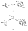
実施形態1に係る通信システムは、携帯端末100、複合機(MFP:Multi-function peripheral)110、MFP110に搭載されたNFCタグ111(近接無線通信タグ)を有する。MFP110は、ソフト的にアクセスポイントとして動作し、携帯端末100との間で無線通信LAN等の無線通信を実行する。
The communication system according to the first embodiment includes a
携帯端末100は、無線LAN等を介した無線通信を実行可能である。ユーザがMFP110のSSIDやセキュリティキーを携帯端末100に入力することで、携帯端末100はMFP110に接続し、携帯端末100は無線LANを介してMFP110と通信することができる。
The
図1(B)は、実施形態1に係る他の通信システムの構成(インフラモード)例を説明する図である。 FIG. 1B is a diagram for explaining an example of the configuration (infrastructure mode) of another communication system according to the first embodiment.
図1(B)に示す通信システムは、携帯端末100、MFP110、MFP110に搭載されたNFCタグ111、アクセスポイント120を有する。
The communication system illustrated in FIG. 1B includes a
MFP110は、アクセスポイント120との間で無線LAN等を介して無線通信を実行する。尚、アクセスポイント120とMFP110との間の通信は、LANケーブル等を用いた有線通信であってもよい。ユーザがアクセスポイント120のSSIDやセキュリティキーを携帯端末100に入力することで、携帯端末100はアクセスポイント120に接続し、そのアクセスポイント120を介してMFP110と通信することができる。
The MFP 110 performs wireless communication with the
図1(A)及び図1、(B)に示す携帯端末100は、無線LANを介してMFP110に印刷ジョブを送信することができ、携帯端末100から印刷ジョブを受信したMFP110は印刷を実行する。
1A, 1B, and 1B can transmit a print job to the MFP 110 via the wireless LAN, and the
また、携帯端末100とMFP110は、NFC等の近接無線通信を実行することができる。実施形態1の場合、MFP110はNFCタグ111を搭載し、そのNFCタグ111にはアクセスポイント120に接続するためのタグ情報(アクセスポイント120のSSIDやセキュリティキー)が記憶されている。携帯端末100は、NFCを用いてMFP110のNFCタグ111のタグ情報を取得し、その取得したタグ情報に基づいてアクセスポイント120に接続することができる。このように、NFC等の近接無線通信で取得した情報を用いて、携帯端末100の通信を無線LAN等の無線通信に切り替えることをハンドオーバーと呼ぶ。このハンドオーバーによって、携帯端末100のユーザは、アクセスポイント120に接続するための情報(アクセスポイント120のSSIDやセキュリティキー)を携帯端末100に入力する手間が解消される。
Further, the
しかしながら、MFP110とアクセスポイント120とが有線で接続されている場合、MFP110はアクセスポイント120の情報を得ることができないため、NFCタグ111にアクセスポイント120の情報を書き込むことができない。また図1(B)のインフラモードであっても、MFP110と携帯端末100が接続するアクセスポイントが同じであるかどうかは確実ではないため、この場合も、NFCタグ111にアクセスポイントの情報を書き込むことができない。よって、携帯端末100で無線LANによる通信に切り替えた後、ユーザは、手動によりアクセスポイントを選択しなければならない。
However, when the
実施形態1では、携帯端末100とMFP110とが接続されたときに、携帯端末100は、MFP110と接続したときのアクセスポイント120を記憶しておく。そして携帯端末100がMFP110のNFCタグ111にタッチした時に、そのタッチしたMFP110と接続したときのアクセスポイントが記憶されていると、無線LANによる通信に切り替えた後、その記憶情報に基づいてアクセスポイントを特定する。これにより、携帯端末100のユーザは、選択したMFP110に接続されているアクセスポイント120を自動的に特定することができる。
In the first embodiment, when the
図2は、実施形態1に係る携帯端末100のハードウェア構成を説明するブロック図である。尚、実施形態1に係る携帯端末100は、例えばスマートフォンやタブレットPC等の装置を想定しているが、無線通信を実行可能な情報処理装置であればよく、このような携帯端末に限定されない。
FIG. 2 is a block diagram illustrating a hardware configuration of the
CPU201は、ROM202や不揮発メモリ204が記憶している制御プログラムをRAM203に展開して、携帯端末100の動作を制御する。ROM202は、CPU201により実行される制御プログラムを記憶している。RAM203は、CPU201の主メモリ、ワークエリア等の一時記憶領域として用いられる。不揮発メモリ204は、写真や電子文書等の様々なデータを記憶するメモリカード等である。RTC(Real Time Clock)205は、時間を計時する。
The
尚、実施形態1に係る携帯端末100の場合、1つのCPU201が後述するフローチャートに示す各処理を実行するものとするが、他の態様であっても構わない。例えば、複数のCPUが協働して後述するフローチャートに示す各処理を実行するようにすることもできる。
In the case of the
操作パネル206は、ユーザのタッチ操作を検出可能なタッチパネル機能を備え、各種画面を表示する。ユーザは操作パネル206にタッチ操作を入力することで、携帯端末100に所望の操作指示を入力することができる。尚、携帯端末100は不図示のハードウェアキーを備えていて、ユーザはこのハードウェアキーを用いて携帯端末100に操作指示を入力することができる。スピーカ207とマイク208は、ユーザが他の携帯端末や固定電話等と電話をする際に使用される。カメラ209は、ユーザの撮像指示に応じて撮像する。カメラ209によって撮像された写真画像は不揮発メモリ204に記憶される。また不揮発メモリ204は、図3に示すMFPアプリケーション300やOS311等のプログラムを記憶している。
The
近接無線通信部210は、NFC等の近接無線通信を実行する。実施形態1では、MFP110がNFCタグ111を備えており、ユーザが携帯端末100をMFP110のNFCタグ111に近付けることで、近接無線通信部210とMFP110のNFCタグ111との間で近接無線通信が確立される。そして近接無線通信部210が、そのNFCタグ111の情報を取得する。尚、近接無線通信部210が実行する近接無線通信はNFCに限らず、例えばBluetoothであってもよい。
The near
無線通信部211は、無線LAN等の無線通信を実行する。携帯端末100の場合、ハンドオーバーを用いることで、ユーザにしてみれば簡単な操作で無線通信部211による無線通信を実現することができる。具体的には、MFP110のNFCタグ111から近接無線通信部210が取得した接続情報(アクセスポイント120のSSIDやセキュリティキー)を用いることで、無線通信部211はアクセスポイント120に接続することができる。
The wireless communication unit 211 performs wireless communication such as a wireless LAN. In the case of the
図3は、実施形態1に係る携帯端末100のソフトウェア構成を説明する機能ブロック図である。図3は、CPU201がROM202や不揮発メモリ204に記憶されている制御プログラムをRAM203に展開して実行することで実現されるソフトウェアの機能ブロック図である。
FIG. 3 is a functional block diagram illustrating the software configuration of the
OS311は、携帯端末100全体の動作を制御するためのソフトウェアである。携帯端末100には、後述するMFPアプリケーション300を含め、様々なアプリケーションをインストールすることができる。OS311はこれらのアプリケーションとの間で情報をやり取りし、アプリケーションから受けた指示に従って、操作パネル206に表示する画面を変更したり、無線通信部211による無線通信を実行する。
The
MFPアプリケーション300は、携帯端末100にインストールされたアプリケーションである。MFPアプリケーション300からMFP110に対して印刷やスキャンなどの指示を行うことができる。携帯端末100には、このMFPアプリケーション300の他に様々なアプリケーションがインストールされているが、それらの説明は省略する。
The
次に、MFPアプリケーション300のソフトウェア構成についてさらに詳しく説明する。
Next, the software configuration of the
画面制御部301は、OS311を介して、操作パネル206に表示する画面を制御する。画面制御部301によって各種操作用の画面が操作パネル206に表示される。また画面制御部301は、操作パネル206を介してユーザが入力した指示を判別する。通信部302は、OS311を介して、近接無線通信部210による近接無線通信や、無線通信部211による無線通信を制御する。無線LAN設定変更部303は、携帯端末100の無線通信に関する無線LANの設定をOS311を介して変更する。計時部304は、RTC205を使用した計時を制御する。印刷ジョブ生成部305は、印刷ジョブを生成する。印刷ジョブ生成部305によって生成された印刷ジョブは、無線通信部211によってMFP110に送信され、MFP110により印刷が実行される。記憶部306は、不揮発メモリ204に様々な情報を一時的に記憶する。スキャン制御部307は、無線通信部211によってMFP110にスキャン指示を行い、MFP110から受信したスキャンデータを表示する。スキャンデータを保存する場合は、記憶部306に記憶される。記憶されたスキャンデータは、ドキュメント管理部308によって管理される。
The
MFP探索部309は、無線通信部211を介して、ネットワーク上に探索コマンドを送信し、受信したレスポンスデータから、該当するMFPをリストアップする。MFP選択部310は、探索されたMFPのリストから、対象となるMFPを選択し、記憶部306に記憶する。MFP選択部310は、過去に選択したMFPのリストも記憶している。 図4は、実施形態1に係る複合機(MFP)110のハードウェア構成の一例を示すブロック図である。
The
複合機110は、ROM402或いは例えばハードディスクなどの大規模記憶装置409に記憶されたソフトウェアを実行するCPU401を備え、CPU401はシステムバス423に接続される各部を総括的に制御する。RAM403は、CPU401の主メモリ、ワークエリア等として機能する。パネル制御部404は、複合機110に備えられた各種ボタン或いはタッチパネル405からの指示入力を制御する。表示制御部406は、例えば液晶表示部等を含む表示部407への表示を制御する。ディスクコントローラ(DKC)408は、大規模記憶装置(HD)409を制御する。ネットワークインタフェースカード(NIC)422は、ネットワーク10を介して、他のネットワーク機器、或いはファイルサーバ等と双方向にデータをやりとりする。無線通信モジュール(WLAN)421は、図1(B)のインフラモードで動作する場合は、アクセスポイント120を介してネットワーク10に接続し、他のネットワーク機器等と双方向にデータをやりとりする。また図1(A)のソフトAPモードで動作する場合は、MFP110はアクセスポイントとして動作し、携帯端末100と直接無線通信することができる。プリンタ部410は、例えば電子写真方式やインクジェット方式等により記録紙に画像を印刷する。スキャナ部420は、原稿の画像を読み取って画像信号として出力する。多くの場合、スキャナ部420には、オプションとしてADF(オートドキュメントフィーダ)(不図示)が装着されており、複数枚の原稿を自動的に搬送して読み取ることができる。尚、大規模記憶装置409は、画像データの一時記憶場所としても使われることがある。NFCタグ111は、起動するアプリケーションの情報や、無線LANハンドオーバーなどを記録している。携帯端末100は、NFCリーダーライタを用いて、このNFCタグ111の情報を読み込む。
The
図5は、実施形態1に係る複合機110のソフトウェア構成を示す機能ブロック図である。この機能を実現するソフトウェアは、ROM402或いはHD409に格納されており、実行時、RAM403に展開されて、CPU401の制御の下に実行される。
FIG. 5 is a functional block diagram illustrating a software configuration of the multifunction peripheral 110 according to the first embodiment. Software that realizes this function is stored in the
パラメータ決定部501は、NFCタグ111に書き込む情報を設定する。具体的には無線LANの接続情報とデバイス名情報をパラメータとして決定する。無線LAN接続情報は、MFP110の接続状態から決定する。ソフトAPモードの場合は、SSIDとパスワードを設定し、インフラモード又は有線接続の場合は空欄とする。NFCタグ書き込み部502は、このパラメータ決定部501で決定したパラメータをNFCタグ111に書き込む。
The
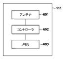
図6は、実施形態1に係るNFCタグ111のハードウェア構成を説明するブロック図である。
FIG. 6 is a block diagram illustrating a hardware configuration of the
アンテナ601は、コントローラ602と接続している。アンテナ601は携帯端末100の近接無線通信部210から電磁誘導によって電力が供給され、コントローラ602の動作電力とする。加えて、近接無線通信部210からの無線通信のアンテナとしての動作をする。コントローラ602は、アンテナ601経由で携帯端末100と通信を行う。加えて通信による読み書き指示に従って、メモリ603に対して読み書き処理を行う。それにより後ほど述べる、MACアドレスなどのMFP110情報を保持し、必要に応じてその情報を、アンテナ601経由で送信することができる。
The
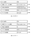
図7は、実施形態1に係るNFCタグ111に書き込まれる情報の一例を示す図である。図7(A)は、図1(A)のソフトAPモードの場合の情報を示し、図7(B)は、図1(B)のインフラモードの場合の情報を示している。
FIG. 7 is a diagram illustrating an example of information written to the
起動アプリケーション情報701は、携帯端末100をNFCタグ111にタッチした場合に起動するアプリケーション名を記載する。図7の例では、MFPアプリケーション300「com.example.printapp」を起動することを示している。無線LAN接続情報702は、このMFP110に接続できるアクセスポイント120のSSIDとパスワード情報を含んでいる。デバイス情報703は、ネットワーク接続情報であるMACアドレスのレコードを示し、ここではMFP110のMACアドレスを示している。実施形態1では、MACアドレスのみを記載しているが、IPアドレスやUUIDなど、MFP110を区別できる情報の組み合わせであってもよい。デバイス名情報704は、MFP110の名称である「Printer01」を格納している
図7(B)は、インフラモードの場合に書きこまれる内容を示し、この場合はMFP110とアクセスポイントを介して通信するため、無線LAN接続情報702は空欄になっている。
The
図8は、実施形態1に係る携帯端末100がMFP110のNFCタグ111にタッチしたときに実行する処理を説明するフローチャートである。この処理は、ソフトAPモードの場合の処理を示している。実施形態1では、NFCタグ111にタッチした時にMFP110が選択され、無線LANが切り替えられた後に、印刷を実行する処理として説明する。しかし、NFCタグ111にタッチした後の処理は印刷処理でなくてもよく、画面に応じた処理を実行してもよいし、ユーザの手動操作を受けつけてもよい。尚、図8のフローチャートに示す各ステップは、CPU201がROM202或いは不揮発メモリ204に格納されたプログラムをRAM203に展開して実行することによって達成される。
FIG. 8 is a flowchart for describing processing executed when the
まず携帯端末100のユーザは、通信相手となるMFP110のNFCタグ111にタッチする。これによりS801でCPU201は、MFP110のNFCタグ111にタッチされたことを検知すると、そのNFCタグ111に書き込まれているタグ情報を取得してS802に進む。S802でCPU201は、NFCタグ111から取得した情報にSSID(図7(A)の702)が含まれているかどうかを判定し、含まれていれば、そのMFP110はソフトAPモードであると判定してS804に進む。一方、SSIDが含まれていなければインフラモードであると判定してS803に進む。S803のインフラモード時の処理は図9のフローチャートを参照して後述する。
First, the user of the
S804でCPU201は、携帯端末100の無線LANがオフかどうかを判定し、オンであればS806に進むが、オフであればS805に進み、無線LANをオンにしてS806に進む。S806でCPU201は、NFCタグ111から取得したSSIDを、無線LANのSSIDに設定してS807に進む。S807でCPU201は、NFCタグ111から取得したデバイス情報703に基づいて、MFP110のMACアドレスをユニキャストで探索する。そしてS808に進みCPU201は、そのMACアドレスに対応するMFP110から応答があるかどうかを判定し、応答があればS809に進み、そうでなければS810に進む。S809でCPU201は、そのMFP110に対して印刷命令を発行して印刷処理を実行して、この処理を終了する。一方、S810でCPU201は、通信エラーを表示して、この処理を終了する。
In step S804, the
上記処理は、ソフトAPモードで実行される処理である。 The above process is a process executed in the soft AP mode.
図9は、実施形態1に係る携帯端末100が、図8のS803で実行するMFP110がインフラモードであった場合の処理を説明するフローチャートである。
FIG. 9 is a flowchart illustrating processing when the
MFPアプリケーション300は、MFP110とアクセスポイント120との組み合わせ情報テーブルを、例えば図12のように保持している。
The
図12は、実施形態1に係るMFPアプリケーション300に記憶されているMFPとアクセスポイントとを対応付ける組み合わせ情報の一例を示す図である。
FIG. 12 is a diagram illustrating an example of combination information for associating an MFP and an access point stored in the
デバイス情報1201は、MFP110のMACアドレス(識別情報)を示している。アクセスポイント情報1202は、MFP110と接続した時のアクセスポイント120の情報を示し、アクセスポイント120のSSID(アクセスポイントの識別子)とパスワード情報(セキュリティ情報)を含んでいる。
S901でCPU201は、図8のS804と同様に、携帯端末100の無線LANがオフかどうかを判定し、オンであればS903に進むがオフであればS902に進み、CPU201は無線LANをオンにしてS903に進む。このとき特に明示的にアクセスポイントは選択されないが、接続履歴のある、その時点で接続可能なアクセスポイントの中で、最近、接続されたアクセスポイントが選択される。S903でCPU201は、NFCタグ111から取得したデバイス情報703に基づいて、MFP110のMACアドレスにユニキャストで探索を行う。そしてS904に進みCPU201は、MFP110から応答があるかどうかを判定し、応答があればS905に進むが、応答がなければS907に進む。S905でCPU201は、MFP110とアクセスポイント120との組み合わせ情報テーブルを更新してS906に進み、図8のS809と同様に、CPU201は、そのMFP110に対して印刷命令を発行して印刷処理を実行して、この処理を終了する。
In step S901, the
ここでMFP110から応答があって、MFP110との通信に成功したときは、現在接続可能なアクセスポイントの中で、最近、接続されたアクセスポイントを介した通信に成功した場合である。これは家庭やオフィスなどで、よく使用するアクセスポイントを介して接続に成功する場合等に該当する。
Here, when there is a response from the
S907でCPU201は、NFCタグ111から読み取ったMFP110のMACアドレスが、例えば図12に示す組み合わせ情報テーブルに存在しているかどうかを判定し、存在していればS908に進み、なければS911に進む。S908でCPU201は、そのMFP110のMACアドレスと紐づけられているアクセスポイントのSSIDを選択する。そしてS909に進みCPU201は、そのアクセスポイントを介してMFP110のMACアドレスを使用して、ユニキャストによるデバイスの探索を行う。そしてS910でCPU201は、MFP110から応答があるかどうかを判定し、MFP110から応答があればS906に進み、応答がなければS911に進む。S906でCPUは印刷処理を実行して、この処理を終了する。
In step S907, the
S911でCPU201は、操作パネル206に無線LANの設定画面を表示してS912に進む。S912でCPU201は、ユーザからの入力があるかどうかを判定し、あればS913に進み、そうでなければS912を実行する。S913でCPU201は、ユーザの入力がキャンセル指示かどうかを判定し、キャンセル指示であれば、この処理を終了する。一方、キャンセル指示でないときはS914に進む。S914でCPU201は、ユーザが入力したSSIDに基づいてアクセスポイントを選択してS915に進む。S915でCPU201は、そのアクセスポイントを介し、MFP110のMACアドレスを使用してユニキャストによるデバイスの探索を行う。そしてS916でCPU201は、MFP110からの応答があるかどうか判定し、MFP110から応答があればS905に進み、応答がなければS917に進む。S917でCPU201は、操作パネル206に通信エラーメッセージを表示してS911に戻る。
In step S911, the
以上説明したように実施形態1によれば、携帯端末100をMFP110のNFCタグ111に近付けたときに、そのMFP110に紐づけられて記憶されている、過去に通信で使用したことのあるアクセスポイントを自動的に選択することができる。
As described above, according to the first embodiment, when the
従って、ユーザは、アクセスポイントの選択やSSIDの設定などの煩わしい作業を行うことなく、そのアクセスポイントを介して簡単にMFPと接続し、印刷データを送信して印刷させる等の操作を実行させることができる。 Therefore, the user can easily connect to the MFP via the access point without performing troublesome operations such as selecting an access point and setting an SSID, and execute operations such as transmitting print data and printing. Can do.
[実施形態2]
前述の実施形態1では、MFP110がインフラモードの場合、まず、接続履歴があり、その時点で接続可能なアクセスポイントの中で最後に接続されたアクセスポイントを介してMFP110との接続を試みる。そして接続できない場合に、例えば図12に示すような組み合わせ情報テーブルを参照してアクセスポイントを選択していた。しかし、この優先順は逆でも良い。そこで実施形態2では、先に組み合わせ情報テーブルを参照してアクセスポイントを選択する例を説明する。尚、実施形態2に係る携帯端末100、複合機110の構成、及びシステム構成は前述の実施形態1と同じであるため、その説明を省略する。
[Embodiment 2]
In the first embodiment described above, when the
図10は、本発明の実施形態2に係る携帯端末100による、図8のS803の、MFP110がインフラモードであった場合の処理を説明するフローチャートである。尚、図10のフローチャートに示す各ステップは、CPU201がROM202或いは不揮発メモリ204に格納されたプログラムをRAM203に展開して実行することによって達成される。実施形態2では、前述の実施形態1との差分についてのみ説明する。また図10において、図9の処理ステップと同じステップは同じ参照番号を付して、それらの説明を省略する。
FIG. 10 is a flowchart for explaining processing when the
S1001でCPU201は、図9のS907と同様に、NFCタグ111から読み取ったMFP110のMACアドレスが組み合わせ情報テーブルにあるかどうかを判定し、あればS1002に進み、なければS1006に進む。S1002でCPU201は、無線LANがオンになった時に、接続履歴のあるその時点で接続可能なアクセスポイントの中で最後に接続されたアクセスポイントが選択されている。従って、ここではその接続されているアクセスポイントのSSID等をRAM203に記憶してS1003に進む。S1003でCPU201は、S1001で取得した組み合わせ情報テーブルのMACアドレスと紐づけられているアクセスポイントを選択してS1004に進む。S1004でCPU201は、そのアクセスポイントインを介して、MFP110のMACアドレスを使用してユニキャストによるデバイスの探索を行う。そしてS1005でCPU201は、MFP110からの応答があるかどうかを判定し、応答があればS906に進んで印刷を実行し、そうでなければS1006に進む。
In step S1001, the
S1006でCPU201は、S1002で記憶したアクセスポイント、或いは、S1001の時点で、接続していたアクセスポイントを選択してS1007に進む。S1007でCPU201は、NFCタグ111から取得したデバイス情報703に基づいて、MFP110のMACアドレスにユニキャストで探索を行う。そしてS1008でCPU201は、MFP110からの応答があるかどうか判定し、MFP110から応答があればS1009に進み、なければS911に進む。S911〜S917の処理は、図9のフローチャートと同じであるため、その説明を省略する。
In step S1006, the
ステップS1009でCPU201は、例えば図12に示す、MFPとアクセスポイントの組み合わせ情報テーブルを更新する。尚、ここでは各デバイス(ここではMFP)ごとに、デバイスとSSIDの組み合わせを記憶するかどうかを設定できてもよい。
In step S1009, the
以上説明したように実施形態2によれば、携帯端末100をMFP110のNFCタグ111に近付けたときに、MFPと通信可能な適切なアクセスポイントを自動的に選択することができる。また、実施形態2では、過去に通信した履歴の情報を先に参照してアクセスポイントを選択することで、接続実績のあるアクセスポイントを優先させて接続するため、接続までの時間が短縮することができる。
As described above, according to the second embodiment, when the
従って、ユーザは、アクセスポイントの選択などの煩わしい操作を行うことなく、簡単に、インフラモードでMFPと無線接続して、印刷などの操作を実行させることができる。 Therefore, the user can easily perform operations such as printing by wirelessly connecting to the MFP in the infrastructure mode without performing troublesome operations such as selecting an access point.
[実施形態3]
前述の実施形態2では、組み合わせ情報テーブルを参照してアクセスポイントを選択し、その選択したアクセスポイントを介してMFPと接続できなかった場合、接続可能なアクセスポイントの中で最後に接続されたアクセスポイントを選択していた。しかし、その時点で接続可能なアクセスポイントの全てに対して接続を試みてもよい。
[Embodiment 3]
In the above-described second embodiment, when an access point is selected with reference to the combination information table and the MFP cannot be connected via the selected access point, the last connected access point among the connectable access points The point was selected. However, connection may be attempted to all access points that can be connected at that time.
次に本発明の実施形態3として、接続可能なアクセスポイントの全てに対して接続を試みる場合について説明する。尚、実施形態3に係る携帯端末100、複合機110の構成、及びシステム構成は前述の実施形態1と同じであるため、その説明を省略する。
Next, as Embodiment 3 of the present invention, a case where connection is attempted to all connectable access points will be described. Note that the configuration and system configuration of the
図11は、本発明の実施形態3に係る携帯端末100による、図8のS803の、MFP110がインフラモードであった場合の処理を説明するフローチャートである。尚、図11のフローチャートに示す各ステップは、CPU201がROM202或いは不揮発メモリ204に格納されたプログラムをRAM203に展開して実行することによって達成される。実施形態3では、前述の実施形態2との差分についてのみ説明する。また図11において、図9及び図10の処理ステップと同じステップは同じ参照番号を付して、それらの説明を省略する。
FIG. 11 is a flowchart illustrating processing when the
図11のS901,S902,S906,S1001〜S1005の処理は、実施形態2のS1002処理を除いくだけで、同じである。実施形態3では、接続可能な全てのアクセスポイントに対して接続を試みるので、S1002で、そのときに接続されているアクセスポイントを記憶する必要はない。 The processes of S901, S902, S906, and S1001 to S1005 in FIG. 11 are the same except for the process of S1002 of the second embodiment. In the third embodiment, since connection is attempted to all connectable access points, it is not necessary to store the access points connected at that time in S1002.
S1111でCPU201は、OS311から接続可能な全てのアクセスポイント情報のリストを取得してS1112に進む。S1112でCPU201は、S1003で試されたアクセスポイントがあれば、それをリストから除外してS1113に進む。S1113でCPU201は、リストのアクセスポイントの全てに対して接続を試みたかどうかを判定し、全て試したのであればS911に進み、そうでなければS1114に進む。
In step S1111, the
S1114でCPU201は、アクセスポイント情報のリストから次のアクセスポイントを選択してS1115に進む。S1115でCPU201は、そのアクセスポイントを介して、MFP110のMACアドレスを使用してユニキャストによるデバイスの探索を行う。次にS1116でCPU201は、MFP110からの応答があるかどうかを判定し、MFP110から応答があればS1009に進み、図10のS1009と同じ処理を実行する。またSS1116でMFP110からの応答がなければS1113に戻る。S911〜S917の処理は、図9のフローチャートと同じであるため、その説明を省略する。
In step S1114, the
以上説明したように実施形態3によれば、携帯端末100をMFP110のNFCタグ111に近付けたときに、MFPと通信可能な適切なアクセスポイントを自動的に選択することができる。また接続可能な全てのアクセスポイントに対して接続を試みるため、接続できる可能性が高くなる。
As described above, according to the third embodiment, when the
従って、ユーザは、アクセスポイントの選択などの煩わしい処理をすることなく、簡単に印刷などの操作をスムーズに行うことができる。 Accordingly, the user can easily perform printing and the like smoothly without performing troublesome processing such as selection of an access point.
(その他の実施形態)
本発明は、上述の実施形態の1以上の機能を実現するプログラムを、ネットワーク又は記憶媒体を介してシステム又は装置に供給し、そのシステム又は装置のコンピュータにおける1つ以上のプロセッサーがプログラムを読出し実行する処理でも実現可能である。また、1以上の機能を実現する回路(例えば、ASIC)によっても実現可能である。
(Other embodiments)
The present invention supplies a program that realizes one or more functions of the above-described embodiments to a system or apparatus via a network or a storage medium, and one or more processors in a computer of the system or apparatus read and execute the program This process can be realized. It can also be realized by a circuit (for example, ASIC) that realizes one or more functions.
本発明は上記実施の形態に制限されるものではなく、本発明の精神及び範囲から離脱することなく、様々な変更及び変形が可能である。従って、本発明の範囲を公にするために、以下の請求項を添付する。 The present invention is not limited to the above-described embodiment, and various changes and modifications can be made without departing from the spirit and scope of the present invention. Therefore, in order to make the scope of the present invention public, the following claims are attached.
100…携帯端末、110…複合機(MFP)、111…NFCタグ、120…アクセスポイント、201…CPU、202…ROM、203…RAM、204…HDD、205…RTC、206…操作パネル、210…近接無線通信部、211…無線通信部、300…MFPアプリケーション
DESCRIPTION OF
Claims (13)
デバイスとの間で通信が成功した場合に、当該デバイスの識別情報と、接続しているアクセスポイントのSSIDとを対応付けて記憶する記憶手段と、
前記近接無線通信を用いて、近接無線通信タグからタグ情報を取得する取得手段と、
前記記憶手段が記憶しているSSIDの中から、前記タグ情報に含まれている識別情報に対応するSSIDを特定する特定手段と、
前記特定手段によって特定された前記SSIDに接続することで、前記通信装置と、前記タグ情報に含まれている識別情報が示すデバイスと前の間の通信を実行する無線通信手段と、
を有することを特徴とする通信装置。 A communication device capable of performing close proximity wireless communication,
Storage means for storing the identification information of the device and the SSID of the connected access point in association with each other when communication with the device is successful;
An acquisition unit that acquires tag information from a proximity wireless communication tag using the proximity wireless communication;
A specifying unit for specifying an SSID corresponding to the identification information included in the tag information from among the SSIDs stored in the storage unit;
By connecting to the SSID specified by the specifying means, wireless communication means for executing communication between the communication device and the device indicated by the identification information included in the tag information, and the previous,
A communication apparatus comprising:
前記タグ情報にSSIDが含まれていないと前記判定手段によって判定された場合に、前記無線通信手段は、前記特定手段によって特定された前記SSIDに接続し、
前記タグ情報にSSIDが含まれていると前記判定手段によって判定された場合に、前記無線通信手段は、前記タグ情報に含まれているSSIDに接続することを特徴とする請求項1に記載の通信装置。 A determination unit for determining whether or not an SSID is included in the tag information acquired by the acquisition unit;
When the determination unit determines that the tag information does not include an SSID, the wireless communication unit connects to the SSID specified by the specification unit,
The wireless communication unit connects to an SSID included in the tag information when the determination unit determines that an SSID is included in the tag information. Communication device.
前記近接無線通信タグは、NFCタグであることを特徴とする請求項1乃至5のいずれか1項に記載の通信装置。 The proximity wireless communication is NFC,
The communication device according to claim 1, wherein the near field communication tag is an NFC tag.
デバイスとの間で通信が成功した場合に、当該デバイスの識別情報と、接続しているアクセスポイントのSSIDとを対応付けてメモリに記憶する記憶ステップと、
近接無線通信タグからタグ情報を取得する取得ステップと、
前記メモリに記憶したSSIDの中から、前記タグ情報に含まれている識別情報に対応するSSIDを特定する特定ステップと、
前記通信装置と、前記タグ情報に含まれている識別情報が示すデバイスと前の間の通信を、前記特定ステップで特定された前記SSIDに接続することで実行するように前記通信装置を制御する制御ステップと、
を有することを特徴とする通信装置の制御方法。 A communication device control method comprising:
A storage step of storing in the memory the identification information of the device and the SSID of the connected access point in association with each other when communication with the device is successful;
An acquisition step of acquiring tag information from the proximity wireless communication tag;
A specifying step of specifying an SSID corresponding to the identification information included in the tag information from among the SSIDs stored in the memory;
The communication apparatus is controlled to execute communication between the communication apparatus and the device indicated by the identification information included in the tag information by connecting to the SSID specified in the specifying step. Control steps;
A method for controlling a communication apparatus, comprising:
前記タグ情報にSSIDが含まれていないと前記判定ステップで判定された場合に、前記制御ステップにおいて、前記特定ステップで特定された前記SSIDに接続するように前記通信装置を制御し、
前記タグ情報にSSIDが含まれていると前記判定ステップで判定された場合に、前記制御ステップにおいて、前記タグ情報に含まれているSSIDに接続するように前記通信装置を制御することを特徴とする請求項7に記載の通信装置の制御方法。 A determination step of determining whether an SSID is included in the tag information acquired in the acquisition step;
When it is determined in the determination step that the tag information does not include an SSID, in the control step, the communication device is controlled to connect to the SSID specified in the specification step,
When the determination step determines that the tag information includes an SSID, the control step controls the communication device to connect to the SSID included in the tag information. A method for controlling a communication apparatus according to claim 7.
Priority Applications (2)
| Application Number | Priority Date | Filing Date | Title |
|---|---|---|---|
| JP2015042978A JP6562660B2 (en) | 2015-03-04 | 2015-03-04 | COMMUNICATION DEVICE, ITS CONTROL METHOD, AND PROGRAM |
| US15/049,853 US9591436B2 (en) | 2015-03-04 | 2016-02-22 | Communication apparatus, method of controlling the same, and storage medium |
Applications Claiming Priority (1)
| Application Number | Priority Date | Filing Date | Title |
|---|---|---|---|
| JP2015042978A JP6562660B2 (en) | 2015-03-04 | 2015-03-04 | COMMUNICATION DEVICE, ITS CONTROL METHOD, AND PROGRAM |
Publications (3)
| Publication Number | Publication Date |
|---|---|
| JP2016163280A true JP2016163280A (en) | 2016-09-05 |
| JP2016163280A5 JP2016163280A5 (en) | 2018-04-12 |
| JP6562660B2 JP6562660B2 (en) | 2019-08-21 |
Family
ID=56847601
Family Applications (1)
| Application Number | Title | Priority Date | Filing Date |
|---|---|---|---|
| JP2015042978A Expired - Fee Related JP6562660B2 (en) | 2015-03-04 | 2015-03-04 | COMMUNICATION DEVICE, ITS CONTROL METHOD, AND PROGRAM |
Country Status (2)
| Country | Link |
|---|---|
| US (1) | US9591436B2 (en) |
| JP (1) | JP6562660B2 (en) |
Cited By (4)
| Publication number | Priority date | Publication date | Assignee | Title |
|---|---|---|---|---|
| JP2018074385A (en) * | 2016-10-28 | 2018-05-10 | キヤノン株式会社 | Communication device, control method of the same, and program |
| JP2019118005A (en) * | 2017-12-27 | 2019-07-18 | ブラザー工業株式会社 | Terminal device, scanner, and computer program thereof |
| JP2019534598A (en) * | 2016-09-06 | 2019-11-28 | 華為技術有限公司Huawei Technologies Co.,Ltd. | Data sharing method and terminal |
| CN111200806A (en) * | 2018-11-16 | 2020-05-26 | 精工爱普生株式会社 | Terminal device, wireless connection control method, and storage medium |
Families Citing this family (10)
| Publication number | Priority date | Publication date | Assignee | Title |
|---|---|---|---|---|
| JP6179157B2 (en) * | 2013-03-27 | 2017-08-16 | ブラザー工業株式会社 | Information processing apparatus, communication terminal apparatus, and information processing apparatus program |
| JP6184580B1 (en) * | 2016-01-29 | 2017-08-23 | キヤノン株式会社 | Information processing apparatus, control method, and program |
| CN107069840B (en) * | 2016-02-10 | 2022-05-27 | 松下知识产权经营株式会社 | Power storage device, method for controlling power storage device, charging device, method for controlling charging device, and wireless connection setting system |
| JP6619682B2 (en) | 2016-03-31 | 2019-12-11 | キヤノン株式会社 | Information processing apparatus, control method, and program |
| US10674561B2 (en) * | 2016-05-17 | 2020-06-02 | Ricoh Company, Ltd. | Communication system, information processing apparatus, and communication method |
| JP6702096B2 (en) * | 2016-09-01 | 2020-05-27 | コニカミノルタ株式会社 | Information processing device and program |
| JP6635978B2 (en) | 2017-05-11 | 2020-01-29 | キヤノン株式会社 | Program, communication method, and communication system |
| WO2019043839A1 (en) * | 2017-08-30 | 2019-03-07 | 楽天株式会社 | Communication device, communication system, communication method, and communication processing program |
| JP2022047951A (en) * | 2020-09-14 | 2022-03-25 | キヤノン株式会社 | Program, information processing device, control method for information processing device |
| US20220357899A1 (en) * | 2021-05-10 | 2022-11-10 | Kyocera Document Solutions Inc. | Image forming apparatus capable of allocating memory capacity of memory among and depending on different types of processing constituting job to create plurality of memory regions in memory |
Citations (3)
| Publication number | Priority date | Publication date | Assignee | Title |
|---|---|---|---|---|
| JP2013020328A (en) * | 2011-07-08 | 2013-01-31 | Brother Ind Ltd | Information processing program, information processing device, and information processing method |
| JP2014195150A (en) * | 2013-03-28 | 2014-10-09 | Brother Ind Ltd | Communication control program and communication device |
| JP2014239292A (en) * | 2013-06-06 | 2014-12-18 | 富士ゼロックス株式会社 | Communication apparatus and communication program |
Family Cites Families (7)
| Publication number | Priority date | Publication date | Assignee | Title |
|---|---|---|---|---|
| US20050130647A1 (en) * | 2003-10-22 | 2005-06-16 | Brother Kogyo Kabushiki Kaisha | Wireless lan system, communication terminal and communication program |
| JP5463738B2 (en) * | 2008-09-22 | 2014-04-09 | 沖電気工業株式会社 | Wireless communication system, access point, controller, network management apparatus, and access point network identifier setting method |
| KR101807286B1 (en) * | 2011-02-11 | 2017-12-08 | 삼성전자주식회사 | Method and apparatus for performing function in mobile terminal using short range communication |
| US8750180B2 (en) * | 2011-09-16 | 2014-06-10 | Blackberry Limited | Discovering network information available via wireless networks |
| KR101421568B1 (en) * | 2012-07-27 | 2014-07-22 | 주식회사 케이티 | Smart card, device and method for smart card service |
| US9083837B2 (en) * | 2013-03-26 | 2015-07-14 | Xerox Corporation | System and method for keyed operation of devices using near field communication |
| JP2014197262A (en) | 2013-03-29 | 2014-10-16 | ブラザー工業株式会社 | Device control program and information processing apparatus |
-
2015
- 2015-03-04 JP JP2015042978A patent/JP6562660B2/en not_active Expired - Fee Related
-
2016
- 2016-02-22 US US15/049,853 patent/US9591436B2/en not_active Expired - Fee Related
Patent Citations (3)
| Publication number | Priority date | Publication date | Assignee | Title |
|---|---|---|---|---|
| JP2013020328A (en) * | 2011-07-08 | 2013-01-31 | Brother Ind Ltd | Information processing program, information processing device, and information processing method |
| JP2014195150A (en) * | 2013-03-28 | 2014-10-09 | Brother Ind Ltd | Communication control program and communication device |
| JP2014239292A (en) * | 2013-06-06 | 2014-12-18 | 富士ゼロックス株式会社 | Communication apparatus and communication program |
Cited By (8)
| Publication number | Priority date | Publication date | Assignee | Title |
|---|---|---|---|---|
| JP2019534598A (en) * | 2016-09-06 | 2019-11-28 | 華為技術有限公司Huawei Technologies Co.,Ltd. | Data sharing method and terminal |
| US11184754B2 (en) | 2016-09-06 | 2021-11-23 | Huawei Technologies Co., Ltd. | Data sharing method and terminal |
| JP2018074385A (en) * | 2016-10-28 | 2018-05-10 | キヤノン株式会社 | Communication device, control method of the same, and program |
| JP2019118005A (en) * | 2017-12-27 | 2019-07-18 | ブラザー工業株式会社 | Terminal device, scanner, and computer program thereof |
| CN111200806A (en) * | 2018-11-16 | 2020-05-26 | 精工爱普生株式会社 | Terminal device, wireless connection control method, and storage medium |
| JP2020088428A (en) * | 2018-11-16 | 2020-06-04 | セイコーエプソン株式会社 | Terminal equipment, radio connection control method, and radio connection control program |
| JP7159803B2 (en) | 2018-11-16 | 2022-10-25 | セイコーエプソン株式会社 | Terminal device, wireless connection control method and wireless connection control program |
| CN111200806B (en) * | 2018-11-16 | 2024-02-02 | 精工爱普生株式会社 | Terminal device, wireless connection control method, and storage medium |
Also Published As
| Publication number | Publication date |
|---|---|
| JP6562660B2 (en) | 2019-08-21 |
| US20160261975A1 (en) | 2016-09-08 |
| US9591436B2 (en) | 2017-03-07 |
Similar Documents
| Publication | Publication Date | Title |
|---|---|---|
| JP6562660B2 (en) | COMMUNICATION DEVICE, ITS CONTROL METHOD, AND PROGRAM | |
| JP6071949B2 (en) | Information processing apparatus, control method thereof, and program | |
| JP6204882B2 (en) | Information processing apparatus, control method, and program | |
| JP6624792B2 (en) | Information processing apparatus, information processing apparatus control method, and program | |
| US9489163B2 (en) | System and method to provide mobile printing using near field communication | |
| JP6560559B2 (en) | Information processing apparatus, information processing apparatus control method, and program | |
| JP6188497B2 (en) | COMMUNICATION DEVICE, COMMUNICATION DEVICE CONTROL METHOD, AND COMPUTER PROGRAM | |
| JP6487737B2 (en) | Information processing apparatus, control method thereof, and program | |
| JP6371825B2 (en) | Information processing apparatus, control method thereof, and program | |
| JP6182919B2 (en) | Communication program and communication device | |
| JP7302050B2 (en) | Communication device, control method and program | |
| JP7308916B2 (en) | Information processing device, its control method, and application | |
| JP6749729B2 (en) | Information processing apparatus, control method of information processing apparatus, and program | |
| JP2019201410A (en) | Communication system, image processing device, control method thereof, and program | |
| JP6814271B2 (en) | Information processing equipment, its control method, and programs | |
| JP7005734B2 (en) | Information processing equipment, its control method, and programs | |
| JP6622878B2 (en) | Information processing apparatus, control method therefor, and program | |
| JP6466636B2 (en) | Information processing program, information processing apparatus, and information processing method | |
| JP6407377B2 (en) | Information processing apparatus and control method thereof | |
| JP2017212648A (en) | Printer, control method and program device of the same | |
| JP2020072470A (en) | Communication device, control method of communication device, and program | |
| JP2019121990A (en) | Image forming apparatus and control method |
Legal Events
| Date | Code | Title | Description |
|---|---|---|---|
| A521 | Request for written amendment filed |
Free format text: JAPANESE INTERMEDIATE CODE: A523 Effective date: 20180302 |
|
| A621 | Written request for application examination |
Free format text: JAPANESE INTERMEDIATE CODE: A621 Effective date: 20180302 |
|
| A131 | Notification of reasons for refusal |
Free format text: JAPANESE INTERMEDIATE CODE: A131 Effective date: 20181214 |
|
| A977 | Report on retrieval |
Free format text: JAPANESE INTERMEDIATE CODE: A971007 Effective date: 20181212 |
|
| A521 | Request for written amendment filed |
Free format text: JAPANESE INTERMEDIATE CODE: A523 Effective date: 20190212 |
|
| TRDD | Decision of grant or rejection written | ||
| A01 | Written decision to grant a patent or to grant a registration (utility model) |
Free format text: JAPANESE INTERMEDIATE CODE: A01 Effective date: 20190624 |
|
| A61 | First payment of annual fees (during grant procedure) |
Free format text: JAPANESE INTERMEDIATE CODE: A61 Effective date: 20190723 |
|
| R151 | Written notification of patent or utility model registration |
Ref document number: 6562660 Country of ref document: JP Free format text: JAPANESE INTERMEDIATE CODE: R151 |
|
| LAPS | Cancellation because of no payment of annual fees |