JP2016162192A - Sales data processing device - Google Patents
Sales data processing device Download PDFInfo
- Publication number
- JP2016162192A JP2016162192A JP2015040371A JP2015040371A JP2016162192A JP 2016162192 A JP2016162192 A JP 2016162192A JP 2015040371 A JP2015040371 A JP 2015040371A JP 2015040371 A JP2015040371 A JP 2015040371A JP 2016162192 A JP2016162192 A JP 2016162192A
- Authority
- JP
- Japan
- Prior art keywords
- unit
- input unit
- settlement
- data processing
- sales data
- Prior art date
- Legal status (The legal status is an assumption and is not a legal conclusion. Google has not performed a legal analysis and makes no representation as to the accuracy of the status listed.)
- Pending
Links
Images

Landscapes
- Cash Registers Or Receiving Machines (AREA)
Abstract
Description
本発明の実施形態は、販売データ処理装置に関する。 Embodiments described herein relate generally to a sales data processing apparatus.
従来、量販店などにおいて、商品情報入力装置や表示デバイス、決済装置、袋詰台などを集約した販売データ処理装置が用いられている。このような販売データ処理装置は、当該装置を用いて顧客が自らチェックアウトを行えることから、セルフチェックアウト装置やセルフPOS装置などとも呼ばれる。 2. Description of the Related Art Conventionally, a sales data processing apparatus in which a product information input device, a display device, a settlement device, a bagging table, and the like are aggregated is used in a mass sales store or the like. Such a sales data processing device is also referred to as a self-checkout device or a self-POS device because the customer can check out by using the device.
従来あるセルフチェックアウト装置のレイアウトの主流は、以下のようなものである。すなわち、スキャナなどの商品情報入力装置や表示デバイス、決済装置が一体となったメイン装置が中央に配され、その片側に精算前の商品が入った買物籠を載せる台が配され、その反対側に、精算後の商品を詰める袋を載せる台が配されている。 The mainstream layout of a conventional self-checkout device is as follows. In other words, a product information input device such as a scanner, a display device, and a main device in which a payment device is integrated are arranged in the center, and a table on which a shopping basket containing products before settlement is placed on one side, and the other side In addition, there is a table on which bags for packing the products after settlement are placed.
上述のようなレイアウトの従来の主流のセルフチェックアウト装置であると、商品の動線が、メイン装置を挟んで長い。この特徴は、商品を手に取って商品情報を入力し商品を袋詰めするまでの操作性を悪くし、特に商品が多い場合や商品が重い場合に不都合である。また、オペレータ(操作者、顧客)がメイン装置の前に立って作業すると、袋詰台が側方に位置することになり、袋詰めしづらい。 In the conventional mainstream self-checkout device having the layout as described above, the flow line of the product is long across the main device. This feature deteriorates operability from picking up a product, inputting product information, and packing the product, and is inconvenient especially when there are many products or when the products are heavy. Further, when an operator (operator, customer) works while standing in front of the main device, the bagging base is located on the side, making it difficult to pack the bag.
操作性がよく従来よりも短い時間で作業完了できる販売データ処理装置を提供することである。 To provide a sales data processing apparatus that has good operability and can complete the work in a shorter time than before.
実施形態の販売データ処理装置は、入力部と、表示デバイスと、袋詰台と、置台と、決済部と、を備える。入力部は、商品の情報の入力を受け付ける。表示デバイスは、前記入力部の上に位置し、操作者に報知する情報を表示する。袋詰台は、前記入力部の下に位置し、前記入力部による情報受付後の商品を詰める袋を載せるためのものである。置台は、前記袋詰台の側方に位置し、前記入力部による情報受付前の商品を載せるためのものである。決済部は、前記袋詰台の側方であって前記置台の反対側に位置し、前記入力部が受け付けた情報に基づいて会計処理を行う。 The sales data processing apparatus according to the embodiment includes an input unit, a display device, a bagging table, a table, and a settlement unit. The input unit accepts input of product information. The display device is positioned on the input unit and displays information to notify the operator. The bagging table is located under the input unit and is used for placing a bag for packing products after receiving information by the input unit. The pedestal is positioned on the side of the bagging table and is used for placing products before receiving information by the input unit. The settlement unit is located on the side of the bagging table and on the opposite side of the table, and performs an accounting process based on the information received by the input unit.
以下、販売データ処理装置の一実施形態であるセルフチェックアウト装置1について、図面を参照しながら説明する。
Hereinafter, a self-
本実施形態は、入力装置や表示デバイス、決済装置が集約された販売データ処理装置における作業完了までの所要時間を短縮可能なレイアウトを提案する。顧客が自身でチェックアウトを行う場合における商品登録開始から決済完了までの時間の計測結果によると、決済よりも商品登録に時間を要することが多い。したがって、商品登録の所要時間短縮を期待できる装置構成とすることで、装置の使用開始から終了までの時間の短縮に寄与することができると考えられる。そして、当該装置における商品登録の所要時間には、商品情報の入力だけでなく袋詰めの時間も含まれる。そこで、袋詰めまでの操作性向上を特に狙って装置構成した。 The present embodiment proposes a layout that can shorten the time required to complete work in a sales data processing apparatus in which an input device, a display device, and a payment device are integrated. According to the measurement result of the time from the start of product registration to the completion of payment when the customer performs checkout by himself / herself, it takes more time for product registration than payment. Therefore, it can be considered that the apparatus configuration that can be expected to reduce the time required for product registration can contribute to the reduction of the time from the start to the end of use of the apparatus. The time required for product registration in the device includes not only product information input but also bagging time. In view of this, the apparatus was configured with a particular aim of improving operability up to bagging.
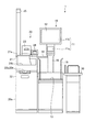
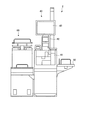
図1は、実施形態のセルフチェックアウト装置1の外観を示す斜視図である。セルフチェックアウト装置1は、中央ユニット10と、決済ユニット20と、籠置台30と、を備えている。
FIG. 1 is a perspective view showing an appearance of a self-
籠置台30は、情報受付前の商品を載置する置台である。言い換えると、籠置台30は、商品登録前の商品を入れた買物籠を載せるための台である。籠置台30は、商品登録・袋詰ユニットである中央ユニット10の側方(図では向かって右側)に配される。
The table 30 is a table on which products before receiving information are placed. In other words, the storage table 30 is a table for placing a shopping basket containing products before product registration. The
中央ユニット10は、籠置台30に置いた買物籠に入っている商品の登録および袋詰めを行うためのユニットである。中央ユニット10は、入力部11、表示デバイス12、袋詰台13、一時置台14などを備えている。
The
入力部11は、商品の情報の入力を受け付ける。セルフチェックアウト装置1は、入力部11による情報入力をもって、商品登録(後に詳述)がなされたとする。
The
入力部11は、例えば、スキャナ11aやタッチパネル11bである。スキャナ11aは、バーコードや二次元コードなどの符号を読み取る読取装置である。当該符号は、例えば、商品に付されたラベル、あるいは一覧表に表示されている。
The
タッチパネル11bは、オペレータ(操作者、顧客)による手入力を受け付ける操作部である。タッチパネル11bは、表示デバイス12の表面に重ねて設けられ、表示デバイス12が表示している画像に応じた操作を受け付ける。例えば、表示デバイス12が商品の情報を表示しているとき、当該商品を選択するオペレータの手入力を、タッチパネル11bが受け付ける。
The
なお、入力部11として、カメラやキーボード、ボタンが設けられていてもよい。カメラは、商品を撮像して画像を出力する撮像装置である。キーボードおよびボタンは、オペレータによる手入力を受け付ける操作部である。
As the
表示デバイス12は、例えば液晶ディスプレイパネルなどであって、入力部11(スキャナ11a)の上に位置し、操作者に報知する情報を表示する。
The
袋詰台13は、入力部11の下に位置し、入力部11による情報受付後の商品を詰める袋を載せるためのものである。言い換えると、袋詰台13は、買い物袋を広げて置くための台であって、商品登録後の商品を置く(すなわち袋詰めする)ための台である。
The bagging table 13 is located under the
上述の籠置台30は、この袋詰台13の側方に位置する。籠置台30の高さと袋詰台13の高さとは、ほぼ同じである。 The above-mentioned table 30 is located on the side of the bagging table 13. The height of the table 30 and the height of the bagging table 13 are substantially the same.
袋詰台13の両側部には、袋支持部15が立てられている。オペレータは、袋支持部15の上端部に袋の持ち手などを引っかけることにより、袋詰台13上にて袋を開いた状態に保つことができる。
ここで、袋詰台13の奥側には、支柱16が立てられている。スキャナ11aおよび表示デバイス12は、支柱16の上端部に取り付けられている。支柱16により、スキャナ11aおよび表示デバイス12と袋詰台13との間が広く開けられて、袋詰め作業のための空間が形成されている。
Here, a
一時置台14は、支柱16に取り付けられて、袋詰台13の上方に位置している。一時置台14は、商品登録後の商品のうち、袋詰めにあたって一時的に除けておきたい商品を置くために設けられている。一時的に除けておきたい商品としては、例えばパンや卵などのような、最上部に袋詰めする(すなわち最後に袋詰めする)ことが望ましいものなどがある。
The temporary table 14 is attached to the
ここで、セルフチェックアウト装置1における商品登録について、より具体的に説明する。まず、セルフチェックアウト装置1は、制御部(不図示)を備えている。制御部は、CPU(Central Processing Unit)、ROM(Read Only Memory)、RAM(Random Access Memory)を有している。
Here, the product registration in the self-
ROMは、CPUが実行する各種プログラムや各種データを記憶する。RAMは、CPUがプログラムを実行する際に一時的にデータやプログラムを記憶する。制御部は、CPUがROMから読み出したプログラムをRAMに展開して実行することにより、自装置が備える各部を統括的に制御する。 The ROM stores various programs executed by the CPU and various data. The RAM temporarily stores data and programs when the CPU executes the programs. The control unit comprehensively controls each unit included in the own apparatus by developing a program read from the ROM by the CPU and executing the program on the RAM.
次に、説明の便宜上、商品には、ラベルが付されているとする。当該ラベルは、商品の情報としての商品コードが符号化された画像を、表示している。スキャナ11a(入力部11)は、符号を読み取って商品コードを出力する。
Next, for convenience of explanation, it is assumed that the product is labeled. The label displays an image in which a product code as product information is encoded. The
制御部は、スキャナ11aが商品コードを出力すると、例えば自装置ないしオンライン接続された外部装置の記憶部に記憶されたPLUファイルを参照する。PLUは、Price Look Upの略である。PLUファイルは、商品コードに関連付けて、商品の名称や価格などを、例えばテーブルの形式で記録したものである。
When the
制御部は、PLUファイルに記録された情報のうち、スキャナ11aが読み取った商品コードに関連付けられた情報を得る。そして、これらの情報を、商品の情報として記録するとともに、商品の価格を購入金額に加算する。これにより、商品登録が行われる。以上のように、セルフチェックアウト装置1は、入力部11による情報入力をもって、商品登録とする。
The control unit obtains information associated with the product code read by the
決済ユニット20は、決済部の一例であって、袋詰台13の側方であって籠置台30の反対側に位置し、入力部11が受け付けた情報に基づいて金銭授受ないし当該金銭授受に代わる情報授受により会計処理を行う。
The
決済ユニット20は、硬貨釣銭機21と紙幣釣銭機22とを備えている。また、決済ユニット20の筐体20aの上面には、プリンタ(印字部)23とカードリーダ(読取装置)24とが載置されている。さらに、決済ユニット20は、警告灯25を備えている。
The
硬貨釣銭機21は、硬貨投入口21aおよび硬貨排出口21bを備えている。紙幣釣銭機22は、紙幣投入口22aおよび紙幣排出口22bを備えている。これら(硬貨投入口21a、硬貨排出口21b、紙幣投入口22a、紙幣排出口22b)は、筐体20aに設けられている。硬貨投入口21aは、硬貨の投入を受け付ける入金口である。硬貨排出口21bは、硬貨を排出する出金口である。紙幣投入口22aは、紙幣の投入を受け付ける入金口である。紙幣排出口22bは、紙幣を排出する出金口である。
The
硬貨排出口21bは、払い出された硬貨を受け止める受皿の形状に形成されている。貨幣(硬貨および紙幣)の入出金のうち最も手間取るのは、硬貨排出口21bに払い出された硬貨の取り出しである。このため、硬貨排出口21bは、硬貨を取り出すにあたって都合のよい高さに設けられている。当該高さは、利用者として想定される人間の身長から考慮して設定される。
The
他の入出金口(硬貨投入口21a、紙幣投入口22a、紙幣排出口22b)は、硬貨排出口21bを高さの基準とし、硬貨排出口21bに可能な限り近く設けられる。硬貨投入口21aは、硬貨の投げ込みやすさを考慮して、漏斗状に形成されている。また、硬貨投入口21aは、硬貨排出口21bよりも高い位置に配されている。紙幣投入口22aおよび紙幣排出口22bは、いずれも上向きに開口した様式で、硬貨排出口21bよりも低い位置に配されている。
Other deposit / withdrawal ports (
プリンタ23は、レシートやクーポン券などを印字発行する。カードリーダ24は、決済に用いられるクレジットカードが記憶する情報を読み取る。警告灯25は、店員による復旧操作が必要などの事態になったとき、当該事態の発生を、光を明滅させるなどにより周囲に報知する。
The
なお、実施にあたって、セルフチェックアウト装置1は、クレジット決済に限らず他の電子決済用の記録媒体が保持するデータを読み取る読取装置(例えば、電子マネー決済用のリーダライタ)を備えていてもよい。
In implementation, the self-
このような構成のセルフチェックアウト装置1の使い勝手について、図2および図3を参照して説明する。図2は、セルフチェックアウト装置1の概略正面図である。図3は、比較のために示す従来のセルフチェックアウト装置(以下、従来装置と称する)2の一例の概略正面図である。
Usability of the self-
従来装置2は、中央ユニット40の下から上へと、決済部41、入力部42、表示デバイス43が配され、それらの一側部に籠置台50、他側部に袋詰台60が配された構成とされている。
In the
従来装置2においては、商品の動線は、図中向かって右のユニットである籠置台50から、中央ユニット40が備える入力部42を経て、左のユニットである袋詰台60へと至る。これに対して、本実施形態のセルフチェックアウト装置1においては、商品の動線は、右のユニットである籠置台30から、中央ユニット10が備える入力部11を経て、同じく中央ユニット10が備える袋詰台13へと至る。したがって、本実施形態のセルフチェックアウト装置1の商品の動線は、従来装置2のものに比して、短くなる。これにより、商品の移動に要する時間が短くなる。
In the
また、本実施形態のセルフチェックアウト装置1は、スキャナ11aを正面に立つオペレータが移動せずそのまま正面で商品の袋詰めを行えるレイアウトであるので、袋詰めがしやすい。このように作業性が向上したことによって、さらに作業の所要時間の短縮を見込むことができる。
Further, the self-
商品登録および袋詰めまで終えると、次にオペレータは決済を行う。セルフチェックアウト装置1は、オペレータから決済に進むための操作を受けると、表示デバイス12に購入商品の価格を合計した代金を表示する。これに伴い、決済ユニット20は、オペレータによる決済操作の受付を開始する。セルフチェックアウト装置1は、決済完了をもって一つの取引を終了し、次の取引の開始を待機する状態へ移る。
When the product registration and bagging are completed, the operator then makes a settlement. When the self-
以上、本実施形態によれば、商品登録の操作性を向上させることができ、これにより商品登録の所要時間を短縮することができ、その結果、取引完了までの時間を短縮することができる。 As described above, according to the present embodiment, it is possible to improve the operability of product registration, thereby shortening the time required for product registration, and as a result, it is possible to shorten the time until the completion of the transaction.
なお、本実施形態では、中央ユニット10と決済ユニット20と籠置台30とがそれぞれ別の筐体を有するセルフチェックアウト装置1として図示および説明しているが、実施にあたってはこれに限らない。つまり、中央ユニット10と決済ユニット20と籠置台30とが一体となったセルフチェックアウト装置でもよいし、中央ユニット10と他の決済ユニット20または籠置台30とが一体となっていてもよい。
In the present embodiment, the
また、本実施形態では触れなかったが、実施にあたって、中央ユニット10は、袋詰台13上の物品の重さを量る計量機能を備えていてもよい。
Although not mentioned in the present embodiment, the
本発明のいくつかの実施形態を説明したが、これらの実施形態は、例として提示したものであり、発明の範囲を限定することは意図していない。これら新規な実施形態は、その他の様々な形態で実施されることが可能であり、発明の要旨を逸脱しない範囲で、種々の省略、置き換え、変更を行うことができる。これら実施形態やその変形は、発明の範囲や要旨に含まれるとともに、特許請求の範囲に記載された発明とその均等の範囲に含まれる。 Although several embodiments of the present invention have been described, these embodiments are presented by way of example and are not intended to limit the scope of the invention. These novel embodiments can be implemented in various other forms, and various omissions, replacements, and changes can be made without departing from the scope of the invention. These embodiments and modifications thereof are included in the scope and gist of the invention, and are included in the invention described in the claims and the equivalents thereof.
1…セルフチェックアウト装置、
10…中央ユニット、
11…入力部、11a…スキャナ、11b…タッチパネル、
12…表示デバイス、
13…袋詰台、14…一時置台、15…袋支持部、16…支柱、
20…決済ユニット、20a…筐体、
21…硬貨釣銭機、21a…硬貨投入口、21b…硬貨排出口、
22…紙幣釣銭機、22a…紙幣投入口、22b…紙幣排出口、
23…プリンタ、24…カードリーダ、25…警告灯、
30…籠置台、
2…従来装置、
40…中央ユニット、41…決済部、42…入力部、43…表示デバイス、
50…籠置台、
60…袋詰台。
1 ... Self-checkout device,
10 ... Central unit,
11 ... input unit, 11a ... scanner, 11b ... touch panel,
12 ... display device,
13 ... packing table, 14 ... temporary table, 15 ... bag support, 16 ... support,
20 ... Payment unit, 20a ... Housing,
21 ... coin change machine, 21a ... coin inlet, 21b ... coin outlet,
22 ... bill change machine, 22a ... bill input port, 22b ... bill discharge port,
23 ... Printer, 24 ... Card reader, 25 ... Warning light,
30 ... A stand,
2 ... conventional device,
40 ...
50 ... Standing table,
60 ... Packing table.
Claims (5)
前記入力部の上に位置し、操作者に報知する情報を表示する表示デバイスと、
前記入力部の下に位置し、前記入力部による情報受付後の商品を詰める袋を載せるための袋詰台と、
前記袋詰台の側方に位置し、前記入力部による情報受付前の商品を載せるための置台と、
前記袋詰台の側方であって前記置台の反対側に位置し、前記入力部が受け付けた情報に基づいて会計処理を行う決済部と、
を備える販売データ処理装置。 An input unit that accepts input of product information;
A display device that is located on the input unit and displays information to notify the operator;
Located under the input unit, a bagging table for placing a bag for packing products after receiving information by the input unit;
Located on the side of the bagging table, a table for placing products before receiving information by the input unit,
A settlement unit that is located on the side of the bagging table and on the opposite side of the table, and that performs accounting processing based on information received by the input unit;
A sales data processing apparatus.
ことを特徴とする請求項1に記載の販売データ処理装置。 The settlement unit is characterized in that at a height between the input unit and the bagging table, a coin insertion port for receiving coins and a coin discharge port for discharging coins are arranged. The sales data processing apparatus according to 1.
ことを特徴とする請求項2に記載の販売データ処理装置。 The sales data processing according to claim 2, wherein the settlement unit includes a banknote insertion port that accepts insertion of banknotes and a banknote discharge port that discharges banknotes below the coin discharge port. apparatus.
ことを特徴とする請求項1〜3のいずれか1つに記載の販売データ処理装置。 The sales data processing apparatus according to claim 1, wherein a printing unit that issues a receipt is arranged on the settlement unit.
ことを特徴とする請求項1〜4のいずれか1つに記載の販売データ処理装置。 The sales data processing apparatus according to claim 1, wherein a reader that reads data held in a recording medium for electronic settlement is arranged on the settlement unit.
Priority Applications (1)
| Application Number | Priority Date | Filing Date | Title |
|---|---|---|---|
| JP2015040371A JP2016162192A (en) | 2015-03-02 | 2015-03-02 | Sales data processing device |
Applications Claiming Priority (1)
| Application Number | Priority Date | Filing Date | Title |
|---|---|---|---|
| JP2015040371A JP2016162192A (en) | 2015-03-02 | 2015-03-02 | Sales data processing device |
Publications (1)
| Publication Number | Publication Date |
|---|---|
| JP2016162192A true JP2016162192A (en) | 2016-09-05 |
Family
ID=56845738
Family Applications (1)
| Application Number | Title | Priority Date | Filing Date |
|---|---|---|---|
| JP2015040371A Pending JP2016162192A (en) | 2015-03-02 | 2015-03-02 | Sales data processing device |
Country Status (1)
| Country | Link |
|---|---|
| JP (1) | JP2016162192A (en) |
Cited By (2)
| Publication number | Priority date | Publication date | Assignee | Title |
|---|---|---|---|---|
| JP7504730B2 (en) | 2020-09-04 | 2024-06-24 | 東芝テック株式会社 | Payment Device |
| JP7519240B2 (en) | 2020-09-04 | 2024-07-19 | 東芝テック株式会社 | Checkout Device |
Citations (4)
| Publication number | Priority date | Publication date | Assignee | Title |
|---|---|---|---|---|
| JPH1069574A (en) * | 1996-06-05 | 1998-03-10 | Ncr Internatl Inc | Device and method for self-service checking out |
| JP2005242728A (en) * | 2004-02-27 | 2005-09-08 | Fujitsu Ltd | Pos system |
| JP2006235816A (en) * | 2005-02-23 | 2006-09-07 | Toshiba Tec Corp | Self-checkout system |
| JP2014052714A (en) * | 2012-09-05 | 2014-03-20 | Toshiba Tec Corp | Currency dispensing device, bill dispensing device, and coin recovery method |
-
2015
- 2015-03-02 JP JP2015040371A patent/JP2016162192A/en active Pending
Patent Citations (4)
| Publication number | Priority date | Publication date | Assignee | Title |
|---|---|---|---|---|
| JPH1069574A (en) * | 1996-06-05 | 1998-03-10 | Ncr Internatl Inc | Device and method for self-service checking out |
| JP2005242728A (en) * | 2004-02-27 | 2005-09-08 | Fujitsu Ltd | Pos system |
| JP2006235816A (en) * | 2005-02-23 | 2006-09-07 | Toshiba Tec Corp | Self-checkout system |
| JP2014052714A (en) * | 2012-09-05 | 2014-03-20 | Toshiba Tec Corp | Currency dispensing device, bill dispensing device, and coin recovery method |
Cited By (2)
| Publication number | Priority date | Publication date | Assignee | Title |
|---|---|---|---|---|
| JP7504730B2 (en) | 2020-09-04 | 2024-06-24 | 東芝テック株式会社 | Payment Device |
| JP7519240B2 (en) | 2020-09-04 | 2024-07-19 | 東芝テック株式会社 | Checkout Device |
Similar Documents
| Publication | Publication Date | Title |
|---|---|---|
| JP6742171B2 (en) | Payment processing device | |
| JP6310885B2 (en) | Product information processing device | |
| JP5037106B2 (en) | Self-checkout device | |
| JP2013045353A (en) | Goods sold sales register data processor | |
| JP5492914B2 (en) | Accounting processing apparatus, computer program, and accounting processing system | |
| JP2015156138A (en) | Commodity sales data processor | |
| JP6088677B1 (en) | Payment device | |
| JP5457494B2 (en) | Self-checkout device | |
| JP2016162192A (en) | Sales data processing device | |
| JP5463247B2 (en) | Self-checkout terminal and program | |
| JP6376993B2 (en) | Self-checkout device | |
| JP2023002640A (en) | Processing device | |
| JP6240110B2 (en) | Sales data processor | |
| JP7519240B2 (en) | Checkout Device | |
| JP2018018554A (en) | Sales data processing device | |
| JP2017138987A (en) | Payment device | |
| WO2022049985A1 (en) | Self-checkout device | |
| JP6205085B2 (en) | Payment device | |
| JP6815803B2 (en) | Sales data processing equipment | |
| JP6522197B2 (en) | Payment device | |
| JP7090689B2 (en) | Sales data processing equipment | |
| JP6214074B2 (en) | Payment device | |
| JP6205084B2 (en) | Payment device | |
| JP6159040B2 (en) | Payment device | |
| JP6088696B1 (en) | Payment device |
Legal Events
| Date | Code | Title | Description |
|---|---|---|---|
| A621 | Written request for application examination |
Free format text: JAPANESE INTERMEDIATE CODE: A621 Effective date: 20160824 |
|
| A131 | Notification of reasons for refusal |
Free format text: JAPANESE INTERMEDIATE CODE: A131 Effective date: 20170711 |
|
| A977 | Report on retrieval |
Free format text: JAPANESE INTERMEDIATE CODE: A971007 Effective date: 20170714 |
|
| A02 | Decision of refusal |
Free format text: JAPANESE INTERMEDIATE CODE: A02 Effective date: 20170926 |