JP2016157604A - Multipurpose ball - Google Patents
Multipurpose ball Download PDFInfo
- Publication number
- JP2016157604A JP2016157604A JP2015035118A JP2015035118A JP2016157604A JP 2016157604 A JP2016157604 A JP 2016157604A JP 2015035118 A JP2015035118 A JP 2015035118A JP 2015035118 A JP2015035118 A JP 2015035118A JP 2016157604 A JP2016157604 A JP 2016157604A
- Authority
- JP
- Japan
- Prior art keywords
- multipurpose
- wall
- bottom plate
- pole
- opening
- Prior art date
- Legal status (The legal status is an assumption and is not a legal conclusion. Google has not performed a legal analysis and makes no representation as to the accuracy of the status listed.)
- Pending
Links
Images


Landscapes
- Illuminated Signs And Luminous Advertising (AREA)
- Road Signs Or Road Markings (AREA)
- Non-Portable Lighting Devices Or Systems Thereof (AREA)
Abstract
Description
本発明は、多目的ポールに関する。詳しくは目的に応じた機材を収納可能とする多目的ポールに係るものである。 The present invention relates to a multipurpose pole. Specifically, it relates to a multipurpose pole that can store equipment according to the purpose.
近年、公園や街中の沿道に設置されるポールに、照明、防犯、あるいは防災対策としての照明灯、監視カメラやスピーカーを取付けることが行われている。 In recent years, lighting, crime prevention, or lighting as a disaster prevention measure, surveillance cameras, and speakers have been attached to poles installed in parks and roadsides in towns.
例えば、太陽光発電を利用した照明灯として特許文献1に記載されたものが知られている。
For example, what was described in
具体的には、図11に示すように、自然エネルギーを用いて発電する発電部材と、この発電部材により得られた電気を蓄電する蓄電池と、蓄電された電気を用いて点灯する照明部101を、支柱102に設けた構成の照明灯103とされている。
Specifically, as shown in FIG. 11, a power generation member that generates power using natural energy, a storage battery that stores electricity obtained by the power generation member, and an
ここで、支柱102の内部を中空状とし、この中空状内部に、蓄電池や電装部品を載置する複数の載置棚104を有する棚組立部材105を挿脱自在に配設すると共に、支柱102の側面に開口部を設け、この開口部に開閉自在な蓋部材106を設ける構成とされている。
Here, the inside of the
しかしながら、上記特許文献1の発明では、蓋部材が支柱の側面に設けられていることで、施工関係者以外の者でも蓋部材を認識することができ、悪意によって蓋部材を開けて収納された機材を取り出す恐れがある。
However, in the invention of
また、公園や沿道との調和を考慮して設置されるポールの側面に、蓋部材やネジなどが取付けられた状態では、ポールとしてのデザイン性を損ねる恐れがある。 In addition, when a lid member, a screw, or the like is attached to the side surface of a pole installed in consideration of harmony with a park or a roadside, the design as the pole may be impaired.
本発明は、以上の点に鑑みて創案されたものであって、機材の収納を可能とし、かつデザイン性に優れた多目的ポールを提供することを目的とするものである。 The present invention has been made in view of the above points, and an object of the present invention is to provide a multipurpose pole capable of storing equipment and having excellent design.
上記の目的を達成するために、本発明に係る多目的ポールは、方形状の底板と、該底板の各コーナーに下端が連結された支柱と、該支柱の上端に、各コーナーが連結された天板と、前記隣設する各支柱との間に配置され、かつ、少なくとも隣設する一対の支柱間に、同一対の支柱の一方に一端が枢支され、他端が同一対の支柱の他方に着脱可能とされた外壁部とを備える。 In order to achieve the above object, a multipurpose pole according to the present invention includes a rectangular bottom plate, a support column having a lower end connected to each corner of the bottom plate, and a ceiling connected to each upper end of the support column. One end of the same pair of struts is pivoted and the other end is the other of the same pair of struts between the plate and each of the adjacent struts. And an outer wall portion that is detachable.
ここで、方形状の底板と、底板の各コーナーに下端が連結された支柱と、支柱の上端に、各コーナーが連結された天板によって、底板と天板との間に所定の空間を確保することが可能となる。 Here, a predetermined space is secured between the bottom plate and the top plate by a rectangular bottom plate, a column having a lower end connected to each corner of the bottom plate, and a top plate having each corner connected to the upper end of the column. It becomes possible to do.
また、隣設する各支柱との間に配置され、かつ、少なくとも隣設する一対の支柱間に、一対の支柱の一方に一端が枢支され、他端が一対の支柱の他方に着脱可能とされた外壁部部によって、出し入れ自在な収納スペースを形成することが可能となる。
例えば、照明灯などの機材を支柱間に配置される外壁部を開くことで支柱内の収納スペースに設置することが可能となる。
In addition, it is arranged between each adjacent support column, and at least one pair of support columns is supported at one end between at least a pair of adjacent support columns, and the other end is detachable from the other of the pair of support columns. With the outer wall portion thus made, it is possible to form a storage space that can be freely put in and out.
For example, it becomes possible to install equipment such as an illuminating lamp in a storage space in the support by opening an outer wall portion disposed between the support.
また、本発明に係る多目的ポールにおいて、外壁部の一端及び他端の長手方向に沿って覆着可能な覆い板部によって、支柱と外壁部の枢支部分及び支柱と外壁部の着脱部分を覆うことが可能となる。 Further, in the multipurpose pole according to the present invention, the support plate portion that can be covered along the longitudinal direction of one end and the other end of the outer wall portion covers the pivotal support portion of the support column and the outer wall portion and the detachable portion of the support column and the outer wall portion. It becomes possible.
例えば、外壁部を開閉するために取付けられるネジなどが覆い板部で覆われることで悪意によって開けられることを防止することが可能となる。 For example, it is possible to prevent a screw or the like attached to open and close the outer wall portion from being opened maliciously by being covered with the cover plate portion.
また、本発明に係る多目的ポールにおいて、少なくとも底板、及び天板の1つに複数の連結用穴部が設けられる場合には、個々の多目的ポールを積み重ねて設置することが可能となる。
例えば、ボルト・ナットなどの連結部材で個々の多目的ポールの天板及び底板を連結することで複数の機能を備えた多目的ポールとすることが可能となる。
Further, in the multipurpose pole according to the present invention, when a plurality of connecting holes are provided in at least one of the bottom plate and the top plate, the individual multipurpose poles can be stacked and installed.
For example, a multi-purpose pole having a plurality of functions can be obtained by connecting the top and bottom plates of individual multi-purpose poles with connecting members such as bolts and nuts.
また、本発明に係る多目的ポールにおいて、少なくとも底板、及び天板の略中央の1つに、連通用穴部が設けられた場合には、多目的ポール同士を連通状に連結することが可能となる。
例えば、電源ケーブルを連通用穴部に通すことで各多目的ポール内に設置された機器に電力を供給することが可能となる。
Further, in the multipurpose pole according to the present invention, when a communication hole is provided at least at one of the center of the bottom plate and the top plate, the multipurpose poles can be connected in a communication manner. .
For example, it is possible to supply power to devices installed in each multipurpose pole by passing a power cable through the communication hole.
また、本発明に係る多目的ポールにおいて、外壁部の一部が透光部材により形成された場合には、多目的ポール内から透光部材を通して光を照射することが可能となる。
例えば、多目的ポール内にLED灯などの光源を設置することで、透光部材を通して照表示灯として活用することが可能となる。
In addition, in the multipurpose pole according to the present invention, when a part of the outer wall portion is formed of a light transmitting member, it is possible to irradiate light from within the multipurpose pole through the light transmitting member.
For example, by installing a light source such as an LED lamp in a multi-purpose pole, it can be used as an illumination lamp through a translucent member.
また、本発明に係る多目的ポールにおいて、覆い板部は、着脱自在な構成とされた場合には、外壁部の開閉を容易に行うことが可能となる。 In the multipurpose pole according to the present invention, when the cover plate portion is configured to be detachable, the outer wall portion can be easily opened and closed.
また、本発明に係る多目的ポールにおいて、天板上に、一体的に連設された照明部を備える場合には、照明灯として活用することが可能となる。 Moreover, in the multipurpose pole which concerns on this invention, when the illumination part integrally provided on the top plate is provided, it becomes possible to utilize as an illumination lamp.
本発明の多目的ポールによれば、機材の収納を可能とし、かつデザイン性に優れた効果を奏する。 According to the multi-purpose pole of the present invention, it is possible to store equipment and to achieve an effect that is excellent in design.
以下、本発明の実施の形態を図面を参酌しながら詳述する。 Hereinafter, embodiments of the present invention will be described in detail with reference to the drawings.
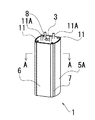
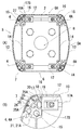
図1は本発明を適用した多目的ポールの一例を説明するための分解模式図、図2は本発明を適用した多目的ポールの一例を説明するための組立て模式図、図3(A)は図2のA−A線における断面を説明するための断面模式図、図3(B)は図2のA−A線における断面の要部拡大模式図である。 FIG. 1 is an exploded schematic view for explaining an example of a multipurpose pole to which the present invention is applied, FIG. 2 is an assembled schematic view for explaining an example of a multipurpose pole to which the present invention is applied, and FIG. FIG. 3B is a schematic cross-sectional view for explaining a cross section taken along the line AA of FIG. 2, and FIG.
ここで示す多目的ポール1は、底板2と天板3との間に配置される一対の支柱(4、4)間に一体的に形成される固定用外壁部5と、一対の支柱(4A、4A)間に一体的に形成される固定用外壁部5Aとから構成されている。
The
更に、支柱(4、4)、支柱(4A、4A)との間に開閉用外壁部(6、6A)が配置され、開閉用外壁部(6、6A)の一端及び、他端の長手方向に沿って配置された覆い板部7とから構成されている。
Further, an opening / closing outer wall (6, 6A) is disposed between the columns (4, 4) and the columns (4A, 4A), and the longitudinal direction of one end and the other end of the opening / closing outer wall (6, 6A). It is comprised from the
ここで、底板2及び天板3の略中央には連通用穴部8が開口され、この連通用穴部8の周囲に4個の連結用穴部9が開口されている。
この連結用穴部9に連結用ボルト11Aが挿通されて上段に積み重ねられる多目的ポール1の底板2の連結用穴部9にナット(図示せず。)などで螺着される。
Here, a
A connecting
更に、底板2の各コーナーに締結用ボルト穴10が穿孔され、締結用ボルト11で支柱(4、4)、支柱(4A、4A)の下端と底板2とが締結固定されている。
Further, a
また、天板3の各コーナーに締結用ボルト穴10が穿孔され、締結用ボルト11で支柱(4、4)、支柱(4A、4A)の上端と天板3とが締結固定されている。
Further, a
更に、底板2及び天板3と支柱(4、4)、支柱(4A、4A)は、ブラケット12で互いに直角状となるようにして連結固定されている。
Further, the
ここで、図3(A)に示すように、固定用外壁部5は、一対の支柱(4、4)との間に湾曲形状に形成された外壁面13と平板形状の内壁面14の二重構造により内部が中空状に形成されている。
Here, as shown in FIG. 3A, the fixing
また、固定用外壁部5Aは、一対の支柱(4A、4A)との間に湾曲形状に形成された外壁面13と平板形状の内壁面14の二重構造により内部が中空状に形成されている。
Further, the fixing
また、支柱(4、4)、支柱(4A、4A)の上下端には、ボルト穴15が設けられ、底板2、あるいは天板3の締結用ボルト穴10と合せた状態で締結用ボルト11によって連結固定されている。
Further,
また、支柱(4、4)、支柱(4A、4A)の断面は、直角三角形状に形成され、互いに対向する支柱(4、4A)、支柱(4、4A)の壁面16の上下に、ナット収納用溝部17が開口される。更に、このナット収納用溝部17と直角状に面する底板2及び天板3に、同様なナット収納用溝部17Aが開口されている。
Further, the cross sections of the support columns (4, 4) and the support columns (4A, 4A) are formed in a right triangle shape, and nuts are placed on the upper and lower sides of the wall surfaces 16 of the support columns (4, 4A) and the support columns (4, 4A) facing each other. The storage groove 17 is opened. Further, a similar
そして、図3(B)に示すように、支柱(4、4)、支柱(4A、4A)の上下の壁面16と底板2及び天板3とが直角状に接する面にブラケット12を配置し、ナット収納用溝部17にナット18及び、ナット収納用溝部17Aにナット(図示せず。)を嵌め入れる。
Then, as shown in FIG. 3B, the
ここで、ブラケット12の支柱(4、4A)のナット収納用溝部(17、17A)に接する面にボルト挿通穴(図示せず。)が形成され、このボルト挿通穴を通してボルト19でナット収納用溝部(17、17A)内のナット18に螺着されている。
Here, a bolt insertion hole (not shown) is formed on the surface of the support column (4, 4A) of the
これにより、支柱(4、4A)と底板2及び天板3とをブラケット12により直角状に固定することが可能となる。
Thereby, it becomes possible to fix the support | pillar (4, 4A), the
また、支柱(4、4A)の外面20の固定用外壁部(5、5A)側には、回転軸嵌入用溝部(21、21A)が上下方向に沿って形成されている。
Further, on the side of the
また、支柱(4、4A)の外面20の略中央の上下に、ナット収納溝部17Bが形成されている。
Further,
また、開閉用外壁部(6、6A)は、図4に示すように、一方の側壁22及び他方の側壁22Aが支柱(4、4A)の外面20に接するように折り曲げ形成され、一方の側壁22の長手方向に沿って回転軸23が設けられている。
As shown in FIG. 4, the opening / closing outer wall portion (6, 6A) is formed so that one
更に、他の側壁22Aに、支柱(4、4A)の外面20に形成されたナット収納溝部17Bに対応する位置に止めネジ挿通穴24が設けられている。
Further, a set
また、一方の側壁22及び他方の側壁22Aの長手方向に沿って突条部(25、25)が一定間隔で突設されている。
In addition, protrusions (25, 25) are provided at regular intervals along the longitudinal direction of the one
更に、突条部(25、25)の上端が外側へ突起された係留用突部(26、26)が形成されている。 Further, anchoring protrusions (26, 26) are formed in which the upper ends of the protrusions (25, 25) protrude outward.
ここで、図5に示すように、一方の支柱(4、4A)の外面20の回転軸嵌入用溝部21に、開閉用外壁部(6、6A)の回転軸23が回転自在な状態で嵌め入れられる。
Here, as shown in FIG. 5, the
これにより、回転軸23を起点として開閉用外壁部(6、6A)が開閉自在となると共に、一方の側壁22は一方の支柱(4、4A)の外面20に、他方の側壁22Aは他方の支柱(4、4A)の外面20に接するようにして覆うことが可能となる。
As a result, the opening / closing outer wall portion (6, 6A) can be freely opened and closed with the
更に、前記図3(A)に示すように、他方の支柱(4、4A)の外面20に形成されたナット収納溝部17B内にナット18Aを挿入する。そして、開閉用外壁部(6、6A)の他の側壁22Aに設けられた止めネジ挿通穴(図示せず。)に止めネジ27を挿通してナット18Aに螺着することで、開閉用外壁部(6、6A)を支柱(4、4A)、支柱(4、4A)間に固着することが可能となる。
Further, as shown in FIG. 3A, the
なお、開閉用外壁部(6、6A)を開閉扉として使用することも可能ではあるが、例えば、開閉用外壁部(6、6A)の一方のみを開閉扉として使用する場合には、他方の開閉用外壁部の一方の側壁及び他方の側壁を支柱の外壁面に止めネジで固着する。 Although the opening / closing outer wall (6, 6A) can be used as an opening / closing door, for example, when only one of the opening / closing outer wall (6, 6A) is used as an opening / closing door, One side wall and the other side wall of the outer wall for opening and closing are fixed to the outer wall surface of the column with a set screw.
また、開閉用外壁部(6、6A)の一方の側壁22及び他方の側壁22Aに対して円弧形状に折り曲げ形成された覆い板部7が着脱自在に取付けられる。
Further, the
ここで、覆い板部7の内側面に、開閉用外壁部(6、6A)の一方の側壁22及び他方の側壁22Aの突条部(25、25)の間隔と略同間隔とされ、かつ、合成樹脂素材などの弾性体により形成された突条部(25A、25A)が突設されている。
更に、突条部(25A、25A)の内側に係留用溝部(28、28)が形成されている。
Here, on the inner side surface of the
Furthermore, mooring grooves (28, 28) are formed inside the protrusions (25A, 25A).
そして、覆い板部7の突条部(25A、25A)内に、開閉用外壁部(6、6A)の一方の側壁22及び他方の側壁22Aの突条部(25、25)を押し入れるようにして嵌め込む。これにより、突条部(25、25)の係留用突部(26、26)が係留用溝部(28、28)に係留して覆い板部7の着脱が可能となる。
Then, the one
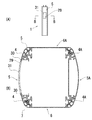
次に、図6(A)は本発明を適用した多目的ポールにおける外壁部の一部が透光部材により形成された場合の一例を説明するための模式図、図6(B)は本発明を適用した多目的ポールの外壁部の一部が透光部材により形成された場合のB−B線における断面模式図である。 Next, FIG. 6A is a schematic diagram for explaining an example in which a part of the outer wall portion of the multipurpose pole to which the present invention is applied is formed of a translucent member, and FIG. It is a cross-sectional schematic diagram in the BB line | wire when a part of outer wall part of the applied multipurpose pole is formed with the translucent member.
ここで、固定用外壁部5の外壁面13の一部に、縦長長方形状の開口部29が開口されている。そして、図6(B)に示すように、この開口部29より若干大き目とされ、かつ、その周縁部に沿って段差部30が周設された透光性部材31が固定用外壁部5の内側より開口部29に嵌め入れられている。
Here, a vertically long
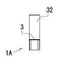
また、図7は本発明を適用した多目的ポールの他の例を説明するための模式図である。 FIG. 7 is a schematic diagram for explaining another example of a multipurpose pole to which the present invention is applied.
ここで示す多目的ポール1Aは、天板3上に円筒形状の照明部32が取り付けられている。この照明部32は、内部に光源(図示せず。)が設けられると共に、乳白色や透明色等の透光性部材により形成されている。
The
ここで、多目的ポール1A内に制御器やトランス等の機材(図示せず。)が収納され、天板3の連通用穴部(図示せず。)を通して電源コード(図示せず。)が配線されている。
Here, equipment (not shown) such as a controller and a transformer is accommodated in the
以上の構成よりなる本発明の多目的ポールでは、図8に示すように、照明部32が設けられた多目的ポール1Aを最上段として複数の多目的ポール1が積み重ねられて照明灯33が組み立てられる。
In the multipurpose pole of the present invention having the above configuration, as shown in FIG. 8, the
ここで、最下段の多目的ポール1と2段目の多目的ポール1は、最下段の多目的ポール1の天板3と2段目の多目的ポール1の底板2が連結用ボルト11Aによって連結される。
Here, in the lowermost
また、2段目の多目的ポール1の天板3と3段目の多目的ポール1の底板2が連結用ボルト11Aによって互いに連結される。そして、3段目の多目的ポール1の天板3と4段目の多目的ポール1の底板2が連結用ボルト11Aによって互いに連結される。
The
更に、4段目の多目的ポール1の天板3と最上段の多目的ポール1Aの底板2が連結用ボルト11Aによって連結される。
Further, the
このようにして組み立てられた照明灯33では、図9に示すように、各多目的ポール1の開閉用外壁部6を開いて機材などを収納すると共に、連通用穴部(図示せず。)を介して電源コードなどの配線を行うことが可能となる。
In the illuminating
具体的には、前記図5において詳述するように、開閉用外壁部6の一方の側壁22及び他方の側壁22Aに取付けられた覆い板部7を取外す。
Specifically, as described in detail in FIG. 5, the
そして、開閉用外壁部6の一方の側壁22Aに螺着された止めネジ27をドライバーなどで取外して支柱4との固着を解除することで開閉用外壁部6を開くことが可能となる。
The opening / closing
また、各多目的ポール1の底板、天板(図示せず。)の略中央の開口された連通用穴部
(図示せず。)が互いに連通状に合わさることで電源コードなどの配線が可能となる。
Further, the connection hole (not shown) opened at the approximate center of the bottom plate and top plate (not shown) of each
また、固定用外壁部(5、5A)の一部が透光性部材31で形成された多目的ポール1では、多目的ポール1内に、例えばプロジェクター、あるいはLED灯を搭載して透光性部材31を通して映射、または発光を行うことが可能となる。
Further, in the
次に、図10は本発明を適用した多目的ポールの使用形態の他の例を説明するための模式図である。 Next, FIG. 10 is a schematic diagram for explaining another example of usage of the multipurpose pole to which the present invention is applied.
ここで、照明部32が設けられた多目的ポール1Aを最上段として複数の多目的ポール1が積み重ねられて照明灯33Aが組み立てられる。
Here, the
例えば、多目的ポール1Aの下段である4段目の多目的ポール1では撮像装置34が設けられている。
For example, the
また、3段目の多目的ポール1の固定用外壁部5にはスピーカー35が設けられ、2段目の多目的ポール1の固定用外壁部5にはインターホーン36が設けられている。
このような構成の照明灯33Aにより、公園や住宅地などの防犯機能を備えた照明灯として活用することが可能となる。
A
The illuminating
本発明によれば、開閉用外壁部の開閉箇所を覆い板で覆うことで開閉式のポールとして外部の者が認識することができず、悪意によるポールの開閉を防止することが可能となる。 According to the present invention, by covering the opening / closing portion of the opening / closing outer wall portion with the cover plate, an outside person cannot recognize the opening / closing type pole, and the opening / closing of the pole by malicious intention can be prevented.
また、様々な目的に応じた機能を備えた多目的ポールを組み合わせることで公園、駅構内、住宅地などの状況に合せたポールの設置が可能となる。 Also, by combining multipurpose poles with functions according to various purposes, it is possible to install poles that match the conditions of parks, station premises, residential areas, etc.
また、開閉用外壁部の開閉箇所を覆い板で覆うことで外表面に凹凸の無い、デザイン性に優れた多目的ポールを作成することが可能となる。 Further, by covering the opening / closing portion of the opening / closing outer wall with a cover plate, it is possible to create a multipurpose pole excellent in design and having no irregularities on the outer surface.
なお、本実施の形態では、外壁部の一端及び他端の長手方向に沿って覆い板部を設けるものであるが、必ずしも覆い板部を設ける必要性はない。 In the present embodiment, the cover plate portion is provided along the longitudinal direction of one end and the other end of the outer wall portion, but it is not always necessary to provide the cover plate portion.
しかし、外壁部を開閉するために取付けられるネジなどが覆い板部で覆われることで悪意によって開けられることを防止することができるという点において覆い板部を設けることが望ましい。 However, it is desirable to provide the cover plate portion in that it can prevent a screw attached to open and close the outer wall portion from being opened maliciously by being covered with the cover plate portion.
また、本実施の形態では、少なくとも底板、及び天板の1つに複数の連結用穴部を設けるものであるが、必ずしも底板、及び天板に連結用穴部を設ける必要性はない。 In this embodiment, at least one of the bottom plate and the top plate is provided with a plurality of connecting holes, but the bottom plate and the top plate are not necessarily provided with connecting holes.
例えば、単体で使用する多目的ポールでの形態では底板、及び天板に連結用穴部を設ける必要性はない。 For example, in the form of a multipurpose pole used alone, there is no need to provide a connecting hole in the bottom plate and the top plate.
また、本実施の形態では、少なくとも底板、及び天板の略中央の1つに、連通用穴部を設けるものであるが、必ずしも底板、及び天板に連通用穴部を設ける必要性はない。 In this embodiment, at least one of the bottom plate and the center of the top plate is provided with a communication hole, but it is not always necessary to provide the communication hole on the bottom plate and the top plate. .
例えば、単体で使用する多目的ポールでの形態では底板、及び天板に連通用穴部を設ける必要性はない。 For example, in the form of a multipurpose pole used alone, there is no need to provide a communication hole in the bottom plate and the top plate.
また、本実施の形態では、外壁部の一部を透光部材により形成するものであるが、必ずしも透光部材により形成する必要性はない。 Moreover, in this Embodiment, although a part of outer wall part is formed with a translucent member, it does not necessarily need to form with a translucent member.
しかし、外壁部の一部を透光部材により形成することで、スポットライト、あるいはフットライトとして活用することが可能となる。 However, by forming a part of the outer wall portion with a translucent member, it can be used as a spotlight or a footlight.
また、本実施の形態では、覆い板部を着脱自在な構成とするものであるが、必ずしも着脱自在な構成とする必要性はない。 In the present embodiment, the cover plate portion is configured to be detachable. However, the configuration is not necessarily required to be detachable.
しかし、覆い板部を取り外すことで容易に開閉用外壁部の開閉が行えるという点において覆い板部を着脱自在な構成とすることが望ましい。 However, it is desirable that the cover plate portion be detachable in that the opening / closing outer wall portion can be easily opened and closed by removing the cover plate portion.
また、本実施の形態では、天板上に、照明部を一体的に連設するものであるが、必ずしも照明部を連設する必要性はない。 Moreover, in this Embodiment, although an illumination part is continuously provided integrally on a top plate, it is not necessarily required to provide an illumination part continuously.
1、1A 多目的ポール
2 底板
3 天板
4、4A 支柱
5、5A 固定用外壁部
6、6A 開閉用外壁部
7 覆い板部
8 連通用穴部
9 連結用穴部
10 締結用ボルト穴
11 締結用ボルト
11A 連結用ボルト
12 ブラケット
13 外壁面
14 内壁面
15 ボルト穴
16 壁面
17、17A、17B ナット収納用溝部
18、18A ナット
19 ボルト
20 外面
21、21A 回転軸嵌入用溝部
22 一方の側壁
22A 他方の側壁
23 回転軸
24 止めネジ挿通穴
25、25A 突条部
26 係留用突部
27 止めネジ
28 係留用溝部
29 開口部
30 段差部
31 透光性部材
32 照明部
33、33A 照明灯
34 撮像装置
35 スピーカー
36 インターホーン
DESCRIPTION OF
Claims (7)
該底板の各コーナーに下端が連結された支柱と、
該支柱の上端に、各コーナーが連結された天板と、
前記隣設する各支柱との間に配置され、かつ、少なくとも隣設する一対の支柱間に、同一対の支柱の一方に一端が枢支され、他端が同一対の支柱の他方に着脱可能とされた外壁部とを備える
多目的ポール。 A rectangular bottom plate;
A column having a lower end connected to each corner of the bottom plate,
A top plate with each corner connected to the upper end of the column;
One end of the same pair of struts is pivoted and the other end is detachable to the other of the same pair of struts. A multi-purpose pole with an outer wall.
請求項1に記載の多目的ポール。 The multipurpose pole according to claim 1, further comprising a cover plate portion that can be covered along a longitudinal direction of one end and the other end of the outer wall portion.
請求項1または請求項2に記載の多目的ポール。 The multipurpose pole according to claim 1 or 2, wherein a plurality of connecting holes are provided in at least one of the bottom plate and the top plate.
請求項1、請求項2または請求項3に記載の多目的ポール。 The multipurpose pole according to claim 1, 2 or 3, wherein a communication hole is provided in at least one of substantially the center of the bottom plate and the top plate.
請求項1、請求項2、請求項3または請求項4に記載の多目的ポール。 The multi-purpose pole according to claim 1, 2, 3, or 4, wherein a part of the outer wall portion is formed of a translucent member.
請求項2、請求項3、請求項4または請求項5に記載の多目的ポール。 The multipurpose pole according to claim 2, claim 3, claim 4, or claim 5, wherein the cover plate portion is configured to be detachable.
請求項1、請求項2、請求項3、請求項4、請求項5または請求項6に記載の多目的ポール。 The multipurpose pole according to claim 1, claim 2, claim 3, claim 4, claim 5, or claim 6, comprising an illuminating unit integrally provided on the top plate.
Priority Applications (1)
| Application Number | Priority Date | Filing Date | Title |
|---|---|---|---|
| JP2015035118A JP2016157604A (en) | 2015-02-25 | 2015-02-25 | Multipurpose ball |
Applications Claiming Priority (1)
| Application Number | Priority Date | Filing Date | Title |
|---|---|---|---|
| JP2015035118A JP2016157604A (en) | 2015-02-25 | 2015-02-25 | Multipurpose ball |
Publications (1)
| Publication Number | Publication Date |
|---|---|
| JP2016157604A true JP2016157604A (en) | 2016-09-01 |
Family
ID=56826374
Family Applications (1)
| Application Number | Title | Priority Date | Filing Date |
|---|---|---|---|
| JP2015035118A Pending JP2016157604A (en) | 2015-02-25 | 2015-02-25 | Multipurpose ball |
Country Status (1)
| Country | Link |
|---|---|
| JP (1) | JP2016157604A (en) |
Cited By (5)
| Publication number | Priority date | Publication date | Assignee | Title |
|---|---|---|---|---|
| JP2021022555A (en) * | 2019-07-27 | 2021-02-18 | ジャージャン フーリンク テクノロジー カンパニー リミテッドZhejiang Hoolink Technology Co., Ltd. | Module assembly type outdoor illumination device and installation method thereof |
| WO2021077556A1 (en) * | 2019-10-21 | 2021-04-29 | 深圳市洲明科技股份有限公司 | Intelligent street lamp |
| WO2023119588A1 (en) * | 2021-12-23 | 2023-06-29 | 日本電気株式会社 | Multi-function pole |
| WO2023152962A1 (en) * | 2022-02-14 | 2023-08-17 | 日本電気株式会社 | Pole and pole unit |
| KR102578753B1 (en) * | 2023-03-06 | 2023-09-15 | (주)와이앤엘 | Prefabricated post for landscape lighting |
Citations (3)
| Publication number | Priority date | Publication date | Assignee | Title |
|---|---|---|---|---|
| JPS5548977U (en) * | 1978-09-29 | 1980-03-31 | ||
| JPS5617608U (en) * | 1979-07-18 | 1981-02-16 | ||
| JPH0577805U (en) * | 1992-03-25 | 1993-10-22 | 小糸工業株式会社 | Lighting equipment |
-
2015
- 2015-02-25 JP JP2015035118A patent/JP2016157604A/en active Pending
Patent Citations (3)
| Publication number | Priority date | Publication date | Assignee | Title |
|---|---|---|---|---|
| JPS5548977U (en) * | 1978-09-29 | 1980-03-31 | ||
| JPS5617608U (en) * | 1979-07-18 | 1981-02-16 | ||
| JPH0577805U (en) * | 1992-03-25 | 1993-10-22 | 小糸工業株式会社 | Lighting equipment |
Cited By (5)
| Publication number | Priority date | Publication date | Assignee | Title |
|---|---|---|---|---|
| JP2021022555A (en) * | 2019-07-27 | 2021-02-18 | ジャージャン フーリンク テクノロジー カンパニー リミテッドZhejiang Hoolink Technology Co., Ltd. | Module assembly type outdoor illumination device and installation method thereof |
| WO2021077556A1 (en) * | 2019-10-21 | 2021-04-29 | 深圳市洲明科技股份有限公司 | Intelligent street lamp |
| WO2023119588A1 (en) * | 2021-12-23 | 2023-06-29 | 日本電気株式会社 | Multi-function pole |
| WO2023152962A1 (en) * | 2022-02-14 | 2023-08-17 | 日本電気株式会社 | Pole and pole unit |
| KR102578753B1 (en) * | 2023-03-06 | 2023-09-15 | (주)와이앤엘 | Prefabricated post for landscape lighting |
Similar Documents
| Publication | Publication Date | Title |
|---|---|---|
| JP2016157604A (en) | Multipurpose ball | |
| KR101235847B1 (en) | Structure lighting of slim type led | |
| KR102027119B1 (en) | Street-lights with accident prevention equipment of crosswalk | |
| JP2011028890A (en) | Outdoor lighting system | |
| KR102100627B1 (en) | Block type flood lighting appliance | |
| JP6023269B1 (en) | Lighting device | |
| RU2659758C1 (en) | Sanitary and technical cabin | |
| JP6481941B2 (en) | lighting equipment | |
| JP2015118733A (en) | Emergency lighting device | |
| KR100942151B1 (en) | The support for a floodlight | |
| JP2005332708A (en) | Lighting apparatus | |
| KR101560351B1 (en) | Lighting pillar for landscaping facilietes | |
| KR20120007901A (en) | Assembly type lamp | |
| JP2006210666A (en) | Mounting structure of solar array panel | |
| JP3178984U (en) | LED lighting structure | |
| RU2431772C1 (en) | Lamp with open architecture | |
| JP4795996B2 (en) | Lighting device | |
| KR200398726Y1 (en) | Mounting structure of frame for lighting | |
| JP6674417B2 (en) | Electrical appliances | |
| KR20130141833A (en) | Lighting apparatus | |
| CN210687819U (en) | Lighting lamp | |
| RU99105U1 (en) | Diffusing LED Luminaire | |
| KR20090080383A (en) | Light Utensils | |
| JP2006059603A (en) | Solar light | |
| KR102156888B1 (en) | Frame for Installing Lighting Device And Spotlight |
Legal Events
| Date | Code | Title | Description |
|---|---|---|---|
| A621 | Written request for application examination |
Free format text: JAPANESE INTERMEDIATE CODE: A621 Effective date: 20170925 |
|
| A977 | Report on retrieval |
Free format text: JAPANESE INTERMEDIATE CODE: A971007 Effective date: 20180622 |
|
| A131 | Notification of reasons for refusal |
Free format text: JAPANESE INTERMEDIATE CODE: A131 Effective date: 20180628 |
|
| A02 | Decision of refusal |
Free format text: JAPANESE INTERMEDIATE CODE: A02 Effective date: 20181213 |