JP2016149361A - Sealed connector - Google Patents
Sealed connector Download PDFInfo
- Publication number
- JP2016149361A JP2016149361A JP2016023457A JP2016023457A JP2016149361A JP 2016149361 A JP2016149361 A JP 2016149361A JP 2016023457 A JP2016023457 A JP 2016023457A JP 2016023457 A JP2016023457 A JP 2016023457A JP 2016149361 A JP2016149361 A JP 2016149361A
- Authority
- JP
- Japan
- Prior art keywords
- connector
- connector housing
- sealing means
- opening
- housing
- Prior art date
- Legal status (The legal status is an assumption and is not a legal conclusion. Google has not performed a legal analysis and makes no representation as to the accuracy of the status listed.)
- Pending
Links
Images


Classifications
-
- H—ELECTRICITY
- H01—ELECTRIC ELEMENTS
- H01R—ELECTRICALLY-CONDUCTIVE CONNECTIONS; STRUCTURAL ASSOCIATIONS OF A PLURALITY OF MUTUALLY-INSULATED ELECTRICAL CONNECTING ELEMENTS; COUPLING DEVICES; CURRENT COLLECTORS
- H01R13/00—Details of coupling devices of the kinds covered by groups H01R12/70 or H01R24/00 - H01R33/00
- H01R13/46—Bases; Cases
- H01R13/52—Dustproof, splashproof, drip-proof, waterproof, or flameproof cases
- H01R13/5205—Sealing means between cable and housing, e.g. grommet
- H01R13/5208—Sealing means between cable and housing, e.g. grommet having at least two cable receiving openings
-
- H—ELECTRICITY
- H01—ELECTRIC ELEMENTS
- H01R—ELECTRICALLY-CONDUCTIVE CONNECTIONS; STRUCTURAL ASSOCIATIONS OF A PLURALITY OF MUTUALLY-INSULATED ELECTRICAL CONNECTING ELEMENTS; COUPLING DEVICES; CURRENT COLLECTORS
- H01R13/00—Details of coupling devices of the kinds covered by groups H01R12/70 or H01R24/00 - H01R33/00
- H01R13/46—Bases; Cases
- H01R13/502—Bases; Cases composed of different pieces
- H01R13/506—Bases; Cases composed of different pieces assembled by snap action of the parts
-
- H—ELECTRICITY
- H01—ELECTRIC ELEMENTS
- H01R—ELECTRICALLY-CONDUCTIVE CONNECTIONS; STRUCTURAL ASSOCIATIONS OF A PLURALITY OF MUTUALLY-INSULATED ELECTRICAL CONNECTING ELEMENTS; COUPLING DEVICES; CURRENT COLLECTORS
- H01R43/00—Apparatus or processes specially adapted for manufacturing, assembling, maintaining, or repairing of line connectors or current collectors or for joining electric conductors
- H01R43/20—Apparatus or processes specially adapted for manufacturing, assembling, maintaining, or repairing of line connectors or current collectors or for joining electric conductors for assembling or disassembling contact members with insulating base, case or sleeve
-
- H—ELECTRICITY
- H01—ELECTRIC ELEMENTS
- H01R—ELECTRICALLY-CONDUCTIVE CONNECTIONS; STRUCTURAL ASSOCIATIONS OF A PLURALITY OF MUTUALLY-INSULATED ELECTRICAL CONNECTING ELEMENTS; COUPLING DEVICES; CURRENT COLLECTORS
- H01R2107/00—Four or more poles
-
- H—ELECTRICITY
- H01—ELECTRIC ELEMENTS
- H01R—ELECTRICALLY-CONDUCTIVE CONNECTIONS; STRUCTURAL ASSOCIATIONS OF A PLURALITY OF MUTUALLY-INSULATED ELECTRICAL CONNECTING ELEMENTS; COUPLING DEVICES; CURRENT COLLECTORS
- H01R2201/00—Connectors or connections adapted for particular applications
- H01R2201/04—Connectors or connections adapted for particular applications for network, e.g. LAN connectors
Abstract
Description
本発明は、車両用の密閉型コネクタ、特に車両におけるネットワーク用の密閉型コネクタおよび該コネクタを備えるネットワークラインを製造するための方法に関するものである。 The present invention relates to a sealed connector for a vehicle, in particular, a sealed connector for a network in a vehicle, and a method for manufacturing a network line including the connector.
自動車工学では、ネットワークは、インテリジェントノードを相互接続することを本質とする。ネットワークおよびインテリジェントノードを使用することで車両における信号ラインを効率的に利用できる。同時に安全性および快適性が向上される。しかしながらデータ転送用のネットワークでは、従来の車両の配線と比較すると、その技術的特性を考慮する必要がある。これは、伝送される信号に適応するよう前記ラインを使用する必要があることを意味する。加えて、コンピュータシステムで公知の同軸ケーブル、光ファイバまたはいわゆるツイストペアケーブルが使用される。ツイストペアケーブルは、シールドされたあるいは裸のままの状態で使用される撚られた導体のペアを有するケーブルである。導体のペアは通常は、ケーブルにさらなる機械的安定性を付与する第2の共通の絶縁層を有する。実際にツイストペアケーブルは、とりわけ実用的なものとなるよう提供される。近代の車両におけるノードの数は、新しい特徴部の発展とともに途切れることなく増加している。車両における空間が制限されるとともにその重量も重要であるため、小型化されたコネクタシステムが使用される。小型化されたコネクタシステムは、車両の製造において加工処理することが比較的困難である。また組立て中に、ある程度の剛性が必要となる。その一方で、ネットワーク全体に伝送する必要があるデータの転送速度が上昇している。これは、達成しなければならないさらなる課題をもたらす。信号伝達におけるエラーを回避するためにノード、コネクタおよびケーブルを互いに適応させる必要がある。加えて、ツイストペアケーブルの導体を、電源からターゲットにかけてできるかぎり接近させて提供する必要がある。公知の解決法としては、コネクタをモジュラー方式で構成すること、および別の導体セットとしてネットワーク用ケーブルを提供することが挙げられる。その結果、ネットワーク接続ケーブルを単独で予め組立てることができるため、ケーブルセットの製造における取扱いが容易となった。ネットワーク接続ケーブルは、ケーブルの端部においてコネクタを備えるよう提供され、ケーブルセットのコネクタハウジングに組み込まれる。 In automotive engineering, the network is based on interconnecting intelligent nodes. By using the network and intelligent nodes, the signal lines in the vehicle can be used efficiently. At the same time, safety and comfort are improved. However, it is necessary to consider the technical characteristics of the data transfer network as compared with the conventional vehicle wiring. This means that the line needs to be used to adapt to the transmitted signal. In addition, coaxial cables, optical fibers or so-called twisted pair cables known from computer systems are used. A twisted pair cable is a cable having a pair of twisted conductors that are used in a shielded or bare state. The pair of conductors typically has a second common insulating layer that provides additional mechanical stability to the cable. Indeed, twisted pair cables are provided to be particularly practical. The number of nodes in modern vehicles is increasing uninterrupted with the development of new features. Since the space in the vehicle is limited and its weight is important, a miniaturized connector system is used. Miniaturized connector systems are relatively difficult to process in the manufacture of vehicles. In addition, a certain degree of rigidity is required during assembly. On the other hand, the transfer rate of data that needs to be transmitted over the entire network is increasing. This leads to further challenges that must be achieved. Nodes, connectors and cables need to be adapted to each other to avoid errors in signal transmission. In addition, twisted pair cable conductors need to be provided as close as possible from the power source to the target. Known solutions include configuring the connector in a modular manner and providing the network cable as a separate conductor set. As a result, the network connection cable can be assembled alone in advance, and the handling in manufacturing the cable set becomes easy. The network connection cable is provided with a connector at the end of the cable and is incorporated into the connector housing of the cable set.
車両では、ケーブルのセットを水分やデブリに対して密閉する必要がある。その一例が特許文献1および2に開示されている。しかしながらこの場合、モジュラ化には好ましくない影響が伴う。シーリングのために必要な労力が増える。特に高速ネットワーク接続を伴うモジュラコネクタシステムのシーリングは開発者に大きな課題をもたらす。 In vehicles, the cable set must be sealed against moisture and debris. Examples thereof are disclosed in Patent Documents 1 and 2. In this case, however, the modularization has an undesirable effect. The effort required for sealing increases. In particular, sealing modular connector systems with high-speed network connections poses significant challenges for developers.
本発明の目的は、車両におけるネットワークアプリケーションに使用できる改良された密閉型コネクタを提供することであると理解されたい。本発明の目的は密閉型コネクタを備えるコネクタラインを製造するための方法を提供することでもある。 It is to be understood that the object of the present invention is to provide an improved hermetic connector that can be used for network applications in vehicles. It is also an object of the present invention to provide a method for manufacturing a connector line with a sealed connector.
本発明の目的は、特許請求の範囲の請求項1に記載の対象物および請求項12に記載の方法によって解決される。 The object of the present invention is solved by an object according to claim 1 and a method according to claim 12.
本発明の目的は、特に相補的なコネクタに接続されるよう構成された第1の側と、挿入方向においてキャビティへ展開する少なくとも1つの開口を伴う第2の側と、を有する第1のコネクタハウジングと、第1のコネクタハウジングの少なくとも1つのキャビティ内に保持可能な少なくとも第2のコネクタハウジングと、第1のコネクタハウジングの第2の側に取り付け可能なシーリング手段と、第1のコネクタハウジングの第2の側においてシーリング手段を保持する保持手段と、を備える電気コネクタによって解決される。シーリング手段は、挿入方向において第1のコネクタハウジングの開口と整列される少なくとも1つの開口を備える。シーリング手段における開口は、第1のコネクタハウジングの開口よりも小さい。 It is an object of the present invention to have a first connector having a first side that is specifically configured to be connected to a complementary connector and a second side with at least one opening that extends into the cavity in the insertion direction. A housing, at least a second connector housing that can be held in at least one cavity of the first connector housing, sealing means attachable to a second side of the first connector housing, and a first connector housing The electrical connector comprises a holding means for holding the sealing means on the second side. The sealing means comprises at least one opening aligned with the opening of the first connector housing in the insertion direction. The opening in the sealing means is smaller than the opening in the first connector housing.
本発明の目的はさらに、ネットワークのための接続ラインを製造するための方法であって、
a)第1のコネクタハウジングを提供するステップと、
b)第1のコネクタハウジングの第2の側にシーリング手段を取り付けるステップと、
c)電気的に接続されかつ機械的に取り付けられるネットワークケーブルを備える第2のコネクタハウジングを提供するステップと、
d)シーリング手段における開口を介して、第1のコネクタハウジングの開口に第2のコネクタハウジングを挿入するステップと、
e)第2のコネクタハウジングが第1のハウジングのキャビティ内に受容されかつ保持されるまで、第2のコネクタハウジングを移動させるステップと、
f)シーリング手段が第1のコネクタハウジング上に保持されるように、第1のコネクタハウジングの第2の側に保持手段を取り付けるステップと、
を含む方法によって解決される。
The object of the present invention is further a method for manufacturing a connection line for a network, comprising:
a) providing a first connector housing;
b) attaching sealing means to the second side of the first connector housing;
c) providing a second connector housing comprising an electrically connected and mechanically attached network cable;
d) inserting the second connector housing into the opening of the first connector housing through the opening in the sealing means;
e) moving the second connector housing until the second connector housing is received and retained within the cavity of the first housing;
f) attaching the retaining means to the second side of the first connector housing such that the sealing means is retained on the first connector housing;
It is solved by a method including:
本発明の有利な実施形態は、従属請求項、明細書および図面に示されている。 Advantageous embodiments of the invention are indicated in the dependent claims, the description and the drawings.
一実施形態によれば、第2のコネクタハウジングは、前面および側面を備える。側面は、挿入方向とは反対の方向において前面から延在しており、これら面の間の推移領域は、丸みを帯びておりかつ/または面取りされている。 According to one embodiment, the second connector housing comprises a front surface and a side surface. The side surfaces extend from the front surface in a direction opposite to the insertion direction, and the transition area between these surfaces is rounded and / or chamfered.
弾性材料の開口に尖った角を有する対象物を挿入すると、弾性材料がすぐに裂けてしまうことがある。前面と側面との間の推移領域に丸みを付けたり面取りすることによって、尖った縁部や角によってシーリング手段を破損することなく第2のコネクタをシーリング手段の開口を通して摺動させることができる。 If an object having sharp corners is inserted into the opening of the elastic material, the elastic material may be easily torn. By rounding or chamfering the transition region between the front and side surfaces, the second connector can be slid through the opening of the sealing means without damaging the sealing means by sharp edges or corners.
丸みを帯びたあるいは面取りされた側縁部(挿入方向に平行な推移領域)は、第2のコネクタハウジングを挿入する際にシーリング手段の開口の破損を防止する。円形断面を有するコネクタハウジングを使用する場合には、こうした要件は必須ではない。しかしながら本願の実施形態では、第1のコネクタハウジング内で第2のコネクタハウジングを方向付けることが重要である。 The rounded or chamfered side edge (transition region parallel to the insertion direction) prevents the opening of the sealing means from being damaged when the second connector housing is inserted. These requirements are not essential when using a connector housing having a circular cross section. However, in the present embodiment, it is important to orient the second connector housing within the first connector housing.
別の実施形態では、シーリング手段の開口を介する第2のコネクタハウジングの挿入中にシーリング手段に沿って摺動する前方縁部と側方縁部(推移領域)が丸みを帯びておりかつ/または面取りされている。面取りまたは丸み付けによって尖った縁部を取り除くことで、第2のコネクタハウジングの挿入時に弾性シーリング手段の開口を損傷するリスクが最小となる。なお第2のコネクタハウジングのうち摺動時にシーリング手段と接触する領域のみの鋭さをなくすだけで十分である。 In another embodiment, the front and side edges (transition zone) sliding along the sealing means during insertion of the second connector housing through the opening of the sealing means are rounded and / or It is chamfered. By removing the sharp edges by chamfering or rounding, the risk of damaging the elastic sealing means opening during insertion of the second connector housing is minimized. It is sufficient to eliminate the sharpness only in the region of the second connector housing that contacts the sealing means during sliding.
より好ましくは、シーリング手段は、弾性材料から一体的に形成される。一体的に形成されたシーリング手段を使用することで製造コストが抑えられる。個別の導体シーリングと比較すると、一体的に形成されたシーリング手段は、より安価で製造でき、組立て時の費用効果が高い。さらに重ねられたシーリング手段は、さまざまな通路形状を実現できるように使用されてもよい。より小さな第2のコネクタハウジングが弾性開口を通って挿入されてもよい。 More preferably, the sealing means is integrally formed from an elastic material. Manufacturing costs can be reduced by using integrally formed sealing means. Compared to individual conductor sealing, the integrally formed sealing means can be manufactured at a lower cost and is more cost effective during assembly. Furthermore, overlapping sealing means may be used so that various passage shapes can be realized. A smaller second connector housing may be inserted through the resilient opening.
さらなる実施形態によれば、シーリング手段は、第1のコネクタの第2の側に面する第1の側および/または保持手段に面する第2の側において、凹部を備える。シーリング手段は、この実施形態ではシリコーンから形成され、その第1の側において凹部を有する。第1のハウジングのデザインに応じて、第1のコネクタハウジングの突出部は前記凹部内に突出していてもよい。これら突出部は、シーリング手段を所望のポジションに維持する。そのためシーリング手段の開口を第1のコネクタハウジングの開口と整列させることが保証される。なお、これら凹部はそれら部分を収容することによって占拠されないことが好ましい。シーリング手段の弾性は、シリコーンが拡張のための空間を有する場合に向上される。シーリング手段の第2の側における凹部はさらに、第2のコネクタハウジングが開口を通して挿入される際にシーリング手段の材料の拡張のための空間を提供する。シリコーンは非圧縮性のものであるため、その材料を第1のコネクタハウジングの開口へ向かけて押し込むことなく、開口を拡張できる。 According to a further embodiment, the sealing means comprises a recess on the first side facing the second side of the first connector and / or on the second side facing the holding means. The sealing means is made of silicone in this embodiment and has a recess on its first side. Depending on the design of the first housing, the protrusion of the first connector housing may protrude into the recess. These protrusions maintain the sealing means in the desired position. This ensures that the opening of the sealing means is aligned with the opening of the first connector housing. In addition, it is preferable that these recessed parts are not occupied by accommodating those parts. The elasticity of the sealing means is improved when the silicone has a space for expansion. The recess on the second side of the sealing means further provides a space for expansion of the material of the sealing means when the second connector housing is inserted through the opening. Since the silicone is incompressible, the opening can be expanded without pushing the material into the opening of the first connector housing.
さらなる実施形態によれば、シーリング手段における少なくとも1つの開口は、ネットワークケーブルを弾性的に包囲するよう形成される。シーリング手段における開口のサイズは、第2のコネクタハウジングの形状およびネットワークケーブルの直径に応じて決定される。シーリング手段における開口は、第2のハウジングがシーリング手段を破損することなく開口を通って摺動できるように寸法決めされる。その後、シーリング手段は、ネットワークケーブルをしっかりと包囲する。 According to a further embodiment, at least one opening in the sealing means is formed to elastically surround the network cable. The size of the opening in the sealing means is determined according to the shape of the second connector housing and the diameter of the network cable. The opening in the sealing means is dimensioned so that the second housing can slide through the opening without damaging the sealing means. Thereafter, the sealing means securely surrounds the network cable.
より好ましくは、シーリング手段はシリコーンを含むかシリコーンからなる。シリコーンの使用によって、とりわけ多くの場合にシリコーン製のシーリング手段の製造中にある程度のオイルがシーリング手段上に留まって、第2のコネクタハウジングの挿入を容易にするとの利点が得られる。適切に順応されたデザインによって、シリコーン製のシーリング手段は第1のハウジングに対して成形できる。なお、ここではこの実施形態に関するさらなる説明は省略する。 More preferably, the sealing means comprises or consists of silicone. The use of silicone provides the advantage that, in many cases, some of the oil remains on the sealing means during the manufacture of the silicone sealing means, facilitating the insertion of the second connector housing. With a suitably adapted design, the silicone sealing means can be molded to the first housing. In addition, further description regarding this embodiment is abbreviate | omitted here.
別の実施形態では、保持手段は複数の部分から形成される。本発明の電気コネクタは、製造の最終段階で保持手段を第1のコネクタハウジングの第2の側に取り付ける順序で取り付けられる。この段階で、複数のネットワークケーブルが、特にコネクタが1つ以上の第2のコネクタハウジングを受容するように、第1のコネクタハウジングの第2の側から突出する。保持手段が複数の部分を有するため、保持手段はネットワークケーブルおよびシーリング手段の周囲に位置決めされてもよく、かつシーリング手段は、さらにネットワークケーブル間において、第1のコネクタハウジングの第2の側に保持されてもよい。 In another embodiment, the holding means is formed from a plurality of parts. The electrical connector of the present invention is attached in the order in which the retaining means is attached to the second side of the first connector housing at the final stage of manufacture. At this stage, a plurality of network cables protrude from the second side of the first connector housing, in particular such that the connector receives one or more second connector housings. Since the holding means has a plurality of parts, the holding means may be positioned around the network cable and the sealing means, and the sealing means is further held on the second side of the first connector housing between the network cables. May be.
より好ましくは保持手段のこれら部分は互いに動作可能に接続される。保持手段のこれら部分は、組立て中の取り扱い性を向上させるために互いに接続される。これら部分は、取り付けのために取り集める必要がなく、簡単に紛失されることがない。これら部分は、例えばフィルムヒンジを用いて互いに接続されてもよい。その使用は、接続のポジションによって予め決定される。これら部分は特定の方法のみによって組立て可能であるため、組立て中のエラーが実質的に排除される。 More preferably these parts of the holding means are operatively connected to each other. These parts of the holding means are connected to each other in order to improve handling during assembly. These parts do not need to be collected for installation and are not easily lost. These parts may be connected to each other using, for example, a film hinge. Its use is predetermined by the position of the connection. Since these parts can be assembled only by a specific method, errors during assembly are substantially eliminated.
好ましくは保持手段の1つ以上の部分は、挿入方向に直交する凹部を有する。保持手段は、ネットワークケーブルが凹部に受容されるように、複数のネットワークケーブル間に配置されてもよい。保持手段の別の部分は、ネットワークケーブルが保持手段によって完全に包囲されるように、第1の部分と接続される。特に複数の第2のコネクタハウジングを伴うコネクタを用いる場合、この保持手段は容易にネットワークケーブル間に配置されかつ組立てられてもよい。ネットワークケーブルは開口を通過する必要がないため、組立てが非常に簡単になる。個別の部分が互いに接続された後、これら部分は安定した蓋を形成する。 Preferably, one or more parts of the holding means have a recess perpendicular to the insertion direction. The holding means may be arranged between the plurality of network cables so that the network cables are received in the recesses. Another part of the holding means is connected to the first part so that the network cable is completely surrounded by the holding means. This holding means may be easily arranged and assembled between the network cables, especially when using a connector with a plurality of second connector housings. Since the network cable does not need to pass through the opening, it is very easy to assemble. After the individual parts are connected to one another, these parts form a stable lid.
特に好ましくは保持手段は、挿入方向および/または挿入方向とは反対の方向における突出部を備える。保持手段の突出部は、挿入方向に突出する場合は、保持手段の組立ての最終ステップでシーリング手段の凹部に挿入される。突出部は、開口を広げるように第2のコネクタハウジングを挿入する間にシーリング手段に必要な空間を占める。そのためシーリング手段の開口は、ツイストペアケーブルの絶縁のために広がらずかつ周縁に当接できない。これによってシーリング性が向上する。保持手段の突出部は、挿入方向とは反対の方向において第1のコネクタハウジングの第2の側から突出する場合は、保持手段のための機械的安定効果を有する。こうした突出部の構成は、水の噴流が保持手段に跳ねかかる場合に水貯蔵部が形成されるように選択されてもよい。突出部同士の間の水は、シーリング手段とネットワークケーブルの絶縁部との間の領域における水圧を低減させる。 Particularly preferably, the holding means comprises a protrusion in the insertion direction and / or in the direction opposite to the insertion direction. When the protrusion of the holding means protrudes in the insertion direction, it is inserted into the recess of the sealing means in the final step of assembling the holding means. The protrusion occupies the space required for the sealing means during insertion of the second connector housing to widen the opening. Therefore, the opening of the sealing means is not widened for insulation of the twisted pair cable and cannot be brought into contact with the peripheral edge. This improves the sealing performance. The protrusion of the holding means has a mechanical stability effect for the holding means when protruding from the second side of the first connector housing in the direction opposite to the insertion direction. The configuration of such a protrusion may be selected such that a water reservoir is formed when a jet of water splashes on the holding means. The water between the protrusions reduces the water pressure in the region between the sealing means and the network cable insulation.
特に好ましくは、接続ラインの製造において、第2のコネクタハウジングはシーリング手段の開口を通して完全に挿入される。これによって組立て中の取り扱いが容易となる。これらは、従来の様式では取扱いが困難な非常に小さなコネクタシステムである。 Particularly preferably, in the production of the connection line, the second connector housing is fully inserted through the opening of the sealing means. This facilitates handling during assembly. These are very small connector systems that are difficult to handle in the conventional manner.
別の実施形態によれば、まず保持手段の1つの部分がネットワークケーブル間に配置され、続いて残りの部分がネットワークケーブルの周囲に配置される。これは、ネットワークケーブルが突出する際に通る閉じた面を形成する。個々の部分から、ハウジングにおいてシーリング手段を保持するとともにネットワークケーブルを付加的に密閉するまとまったプレートが形成される。 According to another embodiment, one part of the holding means is first arranged between the network cables and then the remaining part is arranged around the network cable. This forms a closed surface through which the network cable protrudes. From the individual parts, a solid plate is formed which retains the sealing means in the housing and additionally seals the network cable.
別の実施形態によれば、保持手段は、保持手段の突出部がシーリング手段の凹部内に突出するように構成される。これら突出部は凹部からシーリング手段(ここではシリコーン)を変位させ、ネットワークケーブルに対してシーリング手段を押し付ける。それによってシーリング性が向上され、シーリング手段は適所に維持される。 According to another embodiment, the holding means is configured such that the protrusion of the holding means protrudes into the recess of the sealing means. These protrusions displace the sealing means (here, silicone) from the recesses and press the sealing means against the network cable. Thereby, the sealing performance is improved and the sealing means is maintained in place.
以下、本発明について添付の図面を参照してほんの一例としての有利な実施形態に基づいて説明する。 The invention will now be described by way of example only with reference to the accompanying drawings and by way of example only.
図1には、従来技術に基づくモジュラコネクタ10を示す。コネクタは、電線に取り付けられる接触部分を受容するためのチャンバを備える第1のコネクタハウジングを有する。さらに第1のコネクタハウジングは、ツイストペアケーブル101が取り付けられた第2のコネクタ30を受容するためのチャンバ23を有する。このコネクタのコンセプトは、第2のコネクタ30のためのシーリング手段として単一の導体シーリングを使用することである。なおコネクタ全体は密閉されていない。
FIG. 1 shows a
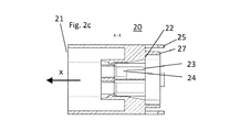
図2aには、本発明のコネクタ10の第1のハウジング20の斜視図を示す。第1のハウジング20は、相補的なコネクタ(図示せず)と接続するよう構成された第1の側21を有する。本発明のコネクタは、相補的なコネクタに接続される挿入方向(x)に移動する。コネクタハウジング20は、第2の側22を含む。第2の側22は複数の開口23を有する。これら開口23は、さらなるコネクタハウジング30を受容するよう構成されている。キャビティ24は、第1の側21と第2の側22との間に設けられており、該キャビティ24内に第2のコネクタハウジング30を保持できる。カラー27が、挿入方向xの反対方向において第2の側から突出する。カラーは、開口23が配置される領域を取り囲む。第2の側の表面および円周カラー27は、シーリング手段40のための受容部を形成する。突起25が、挿入方向(x)の反対方向に第1のコネクタハウジング20から突出する。突起25は、保持手段50を固定するよう機能する。図2bには、第1のコネクタハウジング20の第2の側から見た図が示される。断面線(A)が第1のコネクタハウジング20を直交するよう通って延在する。図2cには、断面線(A)に沿った第1のコネクタハウジング20の断面図が示される。
FIG. 2a shows a perspective view of the
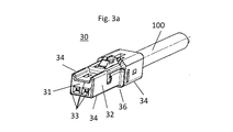
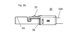
図3aには、本発明のコネクタ10の第2のハウジング30の斜視図を示す。第2のコネクタハウジング30は、第2のコネクタハウジング30が第1のコネクタハウジング20のキャビティ24内に挿入されてそこに保持されるように、構成されている。キャビティ24内に保持するために、ハウジング20,30の両方に戻り止め機構35が設けられる。第2のコネクタハウジング30は、2極ハウジングとして構成されており、略直方体形状を有する。挿入方向(x)に対する第2のコネクタハウジング30の前方部分は、面31,32の間に面取りされた推移領域33を備える。そのため、前面31を取り囲む外周推移領域33は、その鋭利さが低減されている。第2のコネクタハウジング30の前面31と側面32との間の角度部分は挿入方向xとは反対の方向を向いており、かつ2つの縁部まで広げられることによって平坦になされている。外周推移領域33は丸みを帯びていてもよい。直方体ハウジング30の推移領域34はさらに挿入方向(x)に沿って、面取りされるか丸みを付けられている。図3bには、第2のコネクタハウジング30の側面図を示す。第2のコネクタハウジング30は、ここではツーピースの構成要素として示されるが、これは重要なことではない。さらに第2のコネクタハウジング30は面取りされた推移領域36を備える。面取りされた推移領域36は、第2のコネクタハウジング30がシーリング手段40を通って摺動することをサポートする。
FIG. 3a shows a perspective view of the
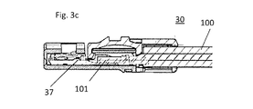
図3cには、挿入方向における第2のコネクタハウジング30の断面図を示す。第2のコネクタハウジング30の内部において、ツイストペアケーブル101が取り付けられた接触要素37が図示される。ツイストペアケーブル101は、ネットワークケーブル100と共通のさらなる絶縁層を有する。
FIG. 3c shows a cross-sectional view of the
図4aには、本発明のコネクタ10のシーリング手段40の斜視図を示す。シーリング手段40はここでは一体形成の平坦なブロックシーリングとして示される。シーリングリップ46,47が外周上および開口内部に形成されている。外周上のシーリングリップ47は、カラー27の内面と協働して、第1のハウジング20の第2の側22を密閉する。開口43内部のシーリングリップ46は、ネットワークケーブル100に密着するように形成される。シーリング手段40の第1の側41および第2の側42には凹部44,45が形成される。凹部44,45は、コネクタ10の組立て中にシーリング手段材料のための受容部として機能する。第2のコネクタハウジング30の1つが開口43を通って挿入される場合に、変位されたシーリング手段材料が凹部44,45に流入でき、開口43がより容易に拡張されてもよい。開口43の上縁部における凹部48は、シーリング手段40を通る挿入時に第2のコネクタハウジング30を整列させるよう機能する。図4bには、シーリング手段40の第2の側42から見た図を示す。シーリング手段40を通って切断する断面線(A)が図示される。図4cにはシーリング手段40の断面図を示す。
FIG. 4a shows a perspective view of the sealing means 40 of the
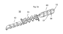
図5aには、本発明のコネクタ10の保持手段50の斜視図を示す。保持手段50は複数の部分で形成される。保持手段50の個々の部分60,61,62はここではフィルムヒンジ56によってともに保持される。フィルムヒンジ56の構成は、保持手段50を組立てるために、所定の作動順序をもたらす。図5bには、保持手段の第1の側51から見た図を示す。保持手段50は、その第1の側51および第2の側52に突出部53,54を有する。第1の側51から突出する突出部53は、組立て状態にある場合には、シーリング手段40の凹部44,45内に突出する。保持手段は、ネットワークケーブル100が保持手段50を通過し得る際に通る凹部70を備える。戻り止め機構63,64は、組立て後に保持手段50の部分60,61,62をともに保持するために設けられる。戻り止め機構63,64は、戻り止め63と、戻り止め63と、該戻り止め63が係合可能な閉鎖タブ64とを含む。図5cには、保持手段50の第2の側52から見た図を示す。第2の側52は、挿入方向(x)とは反対の方向に延出する突出部54を備える。
FIG. 5a shows a perspective view of the holding means 50 of the
図6には、組立て状態にある保持手段50を図示する。戻り止め機構63,64およびヒンジ56はともに部分60,61,62を保持して、蓋形状構造を形成する。保持手段50は、その縁部において、挿入方向xに延在する外周カラー57を備える。戻り止め58がカラー57の外側に配置され、該戻り止め58を用いて、保持手段50を第1のコネクタハウジング20の突起25に固定できる。
FIG. 6 shows the holding means 50 in the assembled state. The
図7には、本発明のコネクタ10の分解図を示す。図7には、コネクタ10を取り付けるための方法が示される。シーリング手段40が第1のコネクタハウジング20に取り付けられる。続いてネットワークケーブル100が取付けられた第2のコネクタハウジング30が、シーリング手段40を介して第1のコネクタハウジング20に挿入される。その後、保持手段50がネットワークケーブル100間に配置され、蓋状構造となるよう組立てられて、第1のコネクタハウジング20に接続される。
FIG. 7 shows an exploded view of the
図8には、本発明のコネクタ10の分解図を示す。この図面には、ネットワークケーブル100間に配置された保持手段50を備えるコネクタ10が図示される。保持手段50はまだ蓋形状となるように折りたたまれていない。
FIG. 8 shows an exploded view of the
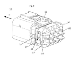
図9には、本発明のコネクタ10の分解図を示す。この図面には、ネットワークケーブル100間に配置された保持手段50を備えるコネクタ10が図示される。保持手段50は蓋形状となるよう折りたたまれている。続く組立てステップでは、保持手段50のカラー57が、第1のコネクタハウジング20のカラー27上に引き上げられるとともに保持手段50の戻り止め58が第1のコネクタハウジング20の突起25ロックされるまで、保持手段50が挿入方向xに移動される。
FIG. 9 shows an exploded view of the
図10には、組立て状態の本発明のコネクタ10の斜視図を示す。ネットワークケーブル100が、シーリング手段40の開口43を通って、第1のコネクタハウジング20の開口23から突出する。保持手段50は、ネットワークライン100間に配置され、第1のコネクタハウジング20の第2の側22に接続される。この接続はスナップ機構25,58を用いてなされる。
FIG. 10 shows a perspective view of the
図11には、組立て状態にある本発明のコネクタ10の断面図を示す。第2のコネクタハウジング30は、第1のコネクタハウジング20のキャビティ24内に収容されて保持されている。第2のコネクタハウジング30における接触部分37は挿入方向xに整列されており、これら接触部分37にネットワークケーブル100のツイストペアケーブル101の導体が接続される。シーリング手段40は第1のコネクタ20の第2の側22と接触する。ネットワークケーブル100は、シーリング手段40の開口43を通って突出する。保持手段50はスナップ機構25,58によって第1のコネクタハウジング20に接続される。保持手段の突出部53は、シーリング手段40の凹部45内に突出し、かつネットワークケーブル100の外側でシーリングリップ46を保持する。
FIG. 11 shows a cross-sectional view of the
10 電気コネクタ
20 第1のコネクタハウジング
21 第1の側
22 第2の側
23 開口
24 キャビティ
25 スナップ機構
27 カラー
30 第2のコネクタハウジング
31 前面
32 側面
33,34,36 推移領域
35 戻り止め機構
37 接触要素
40 シーリング手段
41 第1の側
42 第2の側
43 開口
44,45,48 凹部
46,47 シーリングリップ
48 凹部
50 保持手段
51 第1の側
52 第2の側
53,54 突出部
56 フィルムヒンジ
57 カラー
58 戻り止め
60,61,62 部分
63 戻り止め機構
64 閉鎖タブ
70 凹部
100 ネットワークケーブル
101 ツイストペアケーブル
DESCRIPTION OF
Claims (15)
相補的なコネクタに接続されるよう構成された第1の側(21)と、挿入方向(x)においてキャビティ(24)へ展開する少なくとも1つの開口(23)を備える第2の側(22)と、を有する第1のコネクタハウジング(20)と、
前記第1のコネクタハウジング(20)の前記第2の側(22)に取り付け可能なシーリング手段(40)と、
前記第1のコネクタハウジング(20)の前記第2の側(22)において前記シーリング手段(40)を保持する保持手段(50)と、
を備えており、
前記シーリング手段(40)は、前記挿入方向(x)において前記第1のコネクタハウジングの前記開口(23)と整列される少なくとも1つの開口(43)を備えており、
前記シーリング手段(40)における前記開口(43)は、前記第1のコネクタハウジング(20)の前記開口(23)よりも小さく、かつ、
前記第1のコネクタハウジング(20)の少なくとも1つの前記キャビティ(24)内に少なくとも第2のコネクタハウジング(30)を保持可能であることを特徴とする電気コネクタ(10)。 An electrical connector (10),
A second side (22) comprising a first side (21) configured to be connected to a complementary connector and at least one opening (23) extending into the cavity (24) in the insertion direction (x) A first connector housing (20) having:
Sealing means (40) attachable to the second side (22) of the first connector housing (20);
Holding means (50) for holding the sealing means (40) on the second side (22) of the first connector housing (20);
With
The sealing means (40) comprises at least one opening (43) aligned with the opening (23) of the first connector housing in the insertion direction (x);
The opening (43) in the sealing means (40) is smaller than the opening (23) of the first connector housing (20), and
An electrical connector (10) characterized in that at least a second connector housing (30) can be retained in at least one of said cavities (24) of said first connector housing (20).
前記保持手段は、ネットワークケーブル(100)は前記凹部(70)に受容されるように、ネットワークケーブル(100)間に配置されてもよく、かつ、
前記保持手段の他の部分(60,61,62)は、前記ネットワークケーブル(100)が前記保持手段によって完全に包囲されるように、前記第1の部分に接続されていることを特徴とする請求項8または請求項9に記載の電気コネクタ(10)。 One or more of the portions (60, 61, 62) of the holding means (50) have a recess (70) perpendicular to the insertion direction (x);
The retaining means may be disposed between the network cables (100) such that the network cable (100) is received in the recess (70), and
The other part (60, 61, 62) of the holding means is connected to the first part so that the network cable (100) is completely surrounded by the holding means. Electrical connector (10) according to claim 8 or claim 9.
a)第1のコネクタハウジング(20)を提供するステップと、
b)前記第1のコネクタハウジング(20)の第2の側(22)にシーリング手段(40)を取り付けるステップと、
c)電気的に接続されかつ機械的に取り付けられるネットワークケーブル(100)を備える第2のコネクタハウジング(30)を提供するステップと、
d)前記シーリング手段(40)における開口(43)を介して、前記第1のコネクタハウジング(20)の開口(23)に前記第2のコネクタハウジング(30)を挿入するステップと、
e)第2のコネクタハウジングが前記第1のハウジングのキャビティ(24)内に受容されかつ保持されるまで、前記第2のコネクタハウジング(30)を移動するステップと、
f)前記シーリング手段(40)が前記第1のコネクタハウジング(20)上に保持されるように、前記第1のコネクタハウジング(20)の前記第2の側(22)に保持手段(50)を取り付けるステップと、
を含むことを特徴とする方法。 A method for manufacturing a connection line for a network, comprising:
a) providing a first connector housing (20);
b) attaching sealing means (40) to the second side (22) of the first connector housing (20);
c) providing a second connector housing (30) comprising an electrically connected and mechanically attached network cable (100);
d) inserting the second connector housing (30) into the opening (23) of the first connector housing (20) via the opening (43) in the sealing means (40);
e) moving the second connector housing (30) until the second connector housing is received and retained in the cavity (24) of the first housing;
f) Retaining means (50) on the second side (22) of the first connector housing (20) such that the sealing means (40) is retained on the first connector housing (20). Attaching the step,
A method comprising the steps of:
続いて残りの部分(60,61,62)が、閉じた面が形成されるように前記ネットワークケーブル(100)周りに配置され、該閉じた面を通って前記ネットワークケーブル(100)が突出することを特徴とする請求項12または請求項13に記載の方法。 In method step f), first one of the parts (60, 61, 62) of the holding means (50) is arranged between the network cables (100),
Subsequently, the remaining portions (60, 61, 62) are arranged around the network cable (100) so that a closed surface is formed, and the network cable (100) protrudes through the closed surface. 14. A method according to claim 12 or claim 13 characterized in that.
Applications Claiming Priority (2)
| Application Number | Priority Date | Filing Date | Title |
|---|---|---|---|
| EP15154927.6A EP3057183B1 (en) | 2015-02-12 | 2015-02-12 | Sealed connector |
| EP15154927.6 | 2015-02-12 |
Publications (1)
| Publication Number | Publication Date |
|---|---|
| JP2016149361A true JP2016149361A (en) | 2016-08-18 |
Family
ID=52577629
Family Applications (1)
| Application Number | Title | Priority Date | Filing Date |
|---|---|---|---|
| JP2016023457A Pending JP2016149361A (en) | 2015-02-12 | 2016-02-10 | Sealed connector |
Country Status (5)
| Country | Link |
|---|---|
| US (1) | US20160240957A1 (en) |
| EP (1) | EP3057183B1 (en) |
| JP (1) | JP2016149361A (en) |
| KR (1) | KR102490993B1 (en) |
| CN (1) | CN105896153B (en) |
Cited By (2)
| Publication number | Priority date | Publication date | Assignee | Title |
|---|---|---|---|---|
| WO2021166614A1 (en) * | 2020-02-20 | 2021-08-26 | 住友電装株式会社 | Connector |
| CN114389092A (en) * | 2020-10-02 | 2022-04-22 | 住友电装株式会社 | Connector with a locking member |
Families Citing this family (11)
| Publication number | Priority date | Publication date | Assignee | Title |
|---|---|---|---|---|
| JP6512076B2 (en) * | 2015-11-18 | 2019-05-15 | 住友電装株式会社 | Elastic member and waterproof connector |
| FR3065120B1 (en) * | 2017-04-10 | 2019-06-21 | Dcns Energies | SYSTEM FOR CONNECTING UNDERWATER CABLES |
| CN110603692A (en) * | 2017-05-08 | 2019-12-20 | 莱尼电气系统有限公司 | Method for mounting an electrical connector on a multicore sheathed wire and electrical connector |
| US10148032B1 (en) | 2017-06-05 | 2018-12-04 | Delphi Technologies, Inc. | Sealed electrical connector assembly and wire seal |
| TWI645629B (en) * | 2017-06-14 | 2018-12-21 | 百容電子股份有限公司 | Automotive electronic connectors |
| DE102018209354A1 (en) * | 2017-12-21 | 2019-06-27 | Volkswagen Aktiengesellschaft | Connectors |
| DE102018118774B4 (en) * | 2018-08-02 | 2022-07-14 | Harting Electric Gmbh & Co. Kg | Modular connector system |
| KR102571705B1 (en) | 2018-08-28 | 2023-08-29 | 한국단자공업 주식회사 | Block type waterproof seal |
| GB2589632B (en) | 2019-12-06 | 2023-01-25 | Perkins Engines Co Ltd | Dust cover for an electrical connector in an electronic control unit (ECU) assembly |
| DE102022101417A1 (en) | 2022-01-21 | 2023-07-27 | Aptiv Technologies Limited | Procedure for pre-assembly |
| FR3137511A1 (en) * | 2022-07-04 | 2024-01-05 | Tyco Electronics France Sas | Connector back cover, connector system and assembly method |
Family Cites Families (8)
| Publication number | Priority date | Publication date | Assignee | Title |
|---|---|---|---|---|
| EP1024557A1 (en) * | 1999-01-29 | 2000-08-02 | Sumitomo Wiring Systems, Ltd. | A sealing plug for a watertight connector and a watertight connector |
| JP2000223205A (en) | 1999-01-29 | 2000-08-11 | Sumitomo Wiring Syst Ltd | Rubber stopper for water-proof connector |
| US6361342B1 (en) * | 2000-09-11 | 2002-03-26 | Baker Hughes Incorporated | Pothead with pressure energized lip seals |
| JP2006140019A (en) * | 2004-11-11 | 2006-06-01 | Tyco Electronics Amp Kk | Waterproof connector and seal member |
| JP5227599B2 (en) * | 2008-02-06 | 2013-07-03 | 矢崎総業株式会社 | connector |
| JP2010108765A (en) * | 2008-10-30 | 2010-05-13 | Yazaki Corp | Waterproof connector |
| JP5767909B2 (en) * | 2011-08-30 | 2015-08-26 | 矢崎総業株式会社 | Waterproof connector |
| DE102012212430B4 (en) * | 2012-07-16 | 2017-08-03 | Semikron Elektronik Gmbh & Co. Kg | Connecting device for power semiconductor device with dense connector, power semiconductor device with such a connection device and method for forming a connection with such a connection device |
-
2015
- 2015-02-12 EP EP15154927.6A patent/EP3057183B1/en active Active
-
2016
- 2016-02-04 KR KR1020160014067A patent/KR102490993B1/en active IP Right Grant
- 2016-02-04 CN CN201610139240.9A patent/CN105896153B/en active Active
- 2016-02-10 JP JP2016023457A patent/JP2016149361A/en active Pending
- 2016-02-11 US US15/041,302 patent/US20160240957A1/en not_active Abandoned
Cited By (2)
| Publication number | Priority date | Publication date | Assignee | Title |
|---|---|---|---|---|
| WO2021166614A1 (en) * | 2020-02-20 | 2021-08-26 | 住友電装株式会社 | Connector |
| CN114389092A (en) * | 2020-10-02 | 2022-04-22 | 住友电装株式会社 | Connector with a locking member |
Also Published As
| Publication number | Publication date |
|---|---|
| KR102490993B1 (en) | 2023-01-25 |
| CN105896153B (en) | 2019-10-01 |
| CN105896153A (en) | 2016-08-24 |
| KR20160099490A (en) | 2016-08-22 |
| EP3057183B1 (en) | 2019-09-11 |
| EP3057183A1 (en) | 2016-08-17 |
| US20160240957A1 (en) | 2016-08-18 |
Similar Documents
| Publication | Publication Date | Title |
|---|---|---|
| JP2016149361A (en) | Sealed connector | |
| CN107210542B (en) | Electrical contact arrangement | |
| JP7118675B2 (en) | Methods for making contact carriers, electrical contact units and ready-made cables | |
| CN110383603B (en) | Electrical plug with special grounding of the outer part | |
| KR102616995B1 (en) | Automotive Ethernet connectors and connector assemblies including Ethernet connectors | |
| EP2056412B1 (en) | Electrical connector | |
| JP2015201381A (en) | connector | |
| WO2015049691A1 (en) | Electrical connector with sealing structure | |
| EP3168939B1 (en) | Anti-rotation seal for connector assembly | |
| EP3171460B1 (en) | Electrical connector assembly | |
| US20210066856A1 (en) | Connector for automotive applications | |
| CN105811124A (en) | Systems and methods for forming a conductive wire assembly | |
| JP6824703B2 (en) | Contact device retaining springs, electrical contact device assemblies and electrical connectors | |
| JP2014235901A (en) | Electric connector | |
| JP2018206766A (en) | Contact housing, contact housing receptacle, and electrical connector | |
| KR20210023727A (en) | Assembly comprising a connector and a cable | |
| JP6431471B2 (en) | Sealing member and connector | |
| US11228132B2 (en) | Single pair ethernet field terminable connector | |
| EP3113293A1 (en) | Peripheral wedge seal member | |
| JP2004119294A (en) | Fixing structure of sealing material | |
| JP2014060073A (en) | Connector | |
| EP3869625B1 (en) | Angled plug connection and electrically heated windshield wiper with such an angled plug connection | |
| JP2018010720A (en) | Electric connector | |
| JP7401185B2 (en) | Electrical connection unit and sealing mechanism for electrical connectors and method of forming the same | |
| CN109845049B (en) | Through connector assembly and device with same |