JP2016145644A5 - - Google Patents
Download PDFInfo
- Publication number
- JP2016145644A5 JP2016145644A5 JP2016017837A JP2016017837A JP2016145644A5 JP 2016145644 A5 JP2016145644 A5 JP 2016145644A5 JP 2016017837 A JP2016017837 A JP 2016017837A JP 2016017837 A JP2016017837 A JP 2016017837A JP 2016145644 A5 JP2016145644 A5 JP 2016145644A5
- Authority
- JP
- Japan
- Prior art keywords
- cage
- guide
- shape
- inner peripheral
- Prior art date
- Legal status (The legal status is an assumption and is not a legal conclusion. Google has not performed a legal analysis and makes no representation as to the accuracy of the status listed.)
- Granted
Links
- 230000002093 peripheral Effects 0.000 description 54
- 238000005096 rolling process Methods 0.000 description 50
- 239000000835 fiber Substances 0.000 description 18
- 238000000465 moulding Methods 0.000 description 16
- 239000011347 resin Substances 0.000 description 15
- 229920005989 resin Polymers 0.000 description 15
- 230000037250 Clearance Effects 0.000 description 14
- 230000035512 clearance Effects 0.000 description 14
- 239000004519 grease Substances 0.000 description 14
- 230000003014 reinforcing Effects 0.000 description 14
- 239000010410 layer Substances 0.000 description 13
- 238000004519 manufacturing process Methods 0.000 description 8
- 230000001629 suppression Effects 0.000 description 8
- 230000003746 surface roughness Effects 0.000 description 8
- 239000000463 material Substances 0.000 description 7
- 230000004048 modification Effects 0.000 description 7
- 238000006011 modification reaction Methods 0.000 description 7
- 230000002829 reduced Effects 0.000 description 7
- 210000003491 Skin Anatomy 0.000 description 6
- 239000000314 lubricant Substances 0.000 description 6
- 230000036961 partial Effects 0.000 description 6
- 229920000049 Carbon (fiber) Polymers 0.000 description 5
- 239000004734 Polyphenylene sulfide Substances 0.000 description 5
- 239000004917 carbon fiber Substances 0.000 description 5
- 229920000069 poly(p-phenylene sulfide) Polymers 0.000 description 5
- 239000002344 surface layer Substances 0.000 description 5
- 239000004696 Poly ether ether ketone Substances 0.000 description 4
- 238000005520 cutting process Methods 0.000 description 4
- 239000003365 glass fiber Substances 0.000 description 4
- 238000001746 injection moulding Methods 0.000 description 4
- 239000002184 metal Substances 0.000 description 4
- 239000005011 phenolic resin Substances 0.000 description 4
- 229920002530 poly[4-(4-benzoylphenoxy)phenol] polymer Polymers 0.000 description 4
- 238000010008 shearing Methods 0.000 description 4
- 229920003002 synthetic resin Polymers 0.000 description 4
- 239000000057 synthetic resin Substances 0.000 description 4
- 238000005461 lubrication Methods 0.000 description 3
- 238000000034 method Methods 0.000 description 3
- 239000000203 mixture Substances 0.000 description 3
- 239000000843 powder Substances 0.000 description 3
- 239000004952 Polyamide Substances 0.000 description 2
- 239000004962 Polyamide-imide Substances 0.000 description 2
- 230000002159 abnormal effect Effects 0.000 description 2
- 239000004760 aramid Substances 0.000 description 2
- 229920003235 aromatic polyamide Polymers 0.000 description 2
- 230000023298 conjugation with cellular fusion Effects 0.000 description 2
- 238000005530 etching Methods 0.000 description 2
- 239000000945 filler Substances 0.000 description 2
- 238000002347 injection Methods 0.000 description 2
- 239000007924 injection Substances 0.000 description 2
- 230000013011 mating Effects 0.000 description 2
- 229920002647 polyamide Polymers 0.000 description 2
- 239000011528 polyamide (building material) Substances 0.000 description 2
- 229920002312 polyamide-imide Polymers 0.000 description 2
- 238000003672 processing method Methods 0.000 description 2
- 238000005480 shot peening Methods 0.000 description 2
- 230000021037 unidirectional conjugation Effects 0.000 description 2
- XLYOFNOQVPJJNP-UHFFFAOYSA-N water Substances O XLYOFNOQVPJJNP-UHFFFAOYSA-N 0.000 description 2
- 239000004677 Nylon Substances 0.000 description 1
- 229920001721 Polyimide Polymers 0.000 description 1
- 239000004642 Polyimide Substances 0.000 description 1
- 229910000831 Steel Inorganic materials 0.000 description 1
- 238000005299 abrasion Methods 0.000 description 1
- 230000001154 acute Effects 0.000 description 1
- 230000002411 adverse Effects 0.000 description 1
- 230000001276 controlling effect Effects 0.000 description 1
- 230000000875 corresponding Effects 0.000 description 1
- 230000002950 deficient Effects 0.000 description 1
- 230000000694 effects Effects 0.000 description 1
- 238000003754 machining Methods 0.000 description 1
- 229920001778 nylon Polymers 0.000 description 1
- 230000000717 retained Effects 0.000 description 1
- 239000010959 steel Substances 0.000 description 1
- 229920001169 thermoplastic Polymers 0.000 description 1
- 229920001187 thermosetting polymer Polymers 0.000 description 1
- 239000004416 thermosoftening plastic Substances 0.000 description 1
Images


Description
本発明は、転がり軸受用保持器、及び転がり軸受、並びに転がり軸受用保持器の製造方法に関する。 The present invention relates to a rolling bearing cage, a rolling bearing, and a method for manufacturing a rolling bearing cage.
現在、工作機械の主軸用軸受には、アンギュラ玉軸受等が広く使用されている。工作機械用のアンギュラ玉軸受には、特に使用条件が厳しい場合にはフェノール樹脂保持器が用いられる。フェノール樹脂保持器は、耐摺動摩耗性が高く、軸受に用いた場合に優れた耐久性を発揮する。しかし、低強度で吸水膨張量が大きいため、寸法安定性が低く、設計が制限される不利がある。一般に、フェノール樹脂製の保持器は、寸法公差や案内すきまを小さくできず、保持器音の発生や非同期振れNRRO(Non-Repeatable Run-Out)の悪化を招くことある。また、フェノール樹脂は熱硬化性樹脂であるため、複数のポケットを有する複雑な形状にすることは難しい。そのため、成形後に切削加工が必要で、生産性が低く、大量生産には向かないといった問題がある。
一方、射出成形により作製される合成樹脂製の保持器は、高い生産性を有する。しかし、軸受の使用条件が厳しい場合には、摺動部の潤滑性が低下し、摩耗によって寿命が低下することがある。
上記保持器の耐久性を改善する手段として、特許文献1のように保持器表面に微細凹凸形状を形成し、この表面形状をコントロールする技術がある。この技術によれば、微細凹凸形状の調整によって摺動部の潤滑性や耐久性を高めることができる。
At present, angular contact ball bearings and the like are widely used as spindle bearings for machine tools. For angular contact ball bearings for machine tools, phenol resin cages are used particularly when the use conditions are severe. Phenol resin cages have high sliding wear resistance and exhibit excellent durability when used in bearings. However, since it has a low strength and a large amount of water expansion, there is a disadvantage that the dimensional stability is low and the design is limited. Generally, a cage made of phenol resin cannot reduce dimensional tolerances and guide clearances, and may cause generation of cage noise and non-repeatable run-out (NRRO). Moreover, since a phenol resin is a thermosetting resin, it is difficult to make it into a complicated shape having a plurality of pockets. Therefore, there is a problem that cutting is necessary after molding, productivity is low, and it is not suitable for mass production.
On the other hand, a cage made of synthetic resin produced by injection molding has high productivity. However, when the usage conditions of the bearing are severe, the lubricity of the sliding portion is lowered, and the life may be reduced due to wear.
As means for improving the durability of the cage, there is a technique of forming a fine uneven shape on the surface of the cage and controlling the surface shape as in Patent Document 1. According to this technique, the lubricity and durability of the sliding portion can be improved by adjusting the fine uneven shape.
上記保持器表面の微細凹凸形状は、成形用金型の金型表面を予め微細凹凸形状に加工して、その金型表面の微細凹凸形状を成形品に転写することで得られる。しかし、保持器のポケットはスライドコアにより成形されるため、スライドコアの引き抜き時に、ポケット内周面の微細凹凸形状が金型との剪断によって削り取られることがある。 The fine concavo-convex shape on the surface of the cage can be obtained by processing the mold surface of the molding die into a fine concavo-convex shape in advance and transferring the fine concavo-convex shape on the mold surface to a molded product. However, since the pocket of the cage is formed by the slide core, when the slide core is pulled out, the fine uneven shape on the inner peripheral surface of the pocket may be scraped off by shearing with the mold.
そこで本発明は、保持器のポケットの内周面における微細凹凸形状の損傷を抑制して、耐久性が高く生産性のよい転がり軸受用保持器、及びこれを備えた転がり軸受、並びに転がり軸受用保持器の製造方法を提供することを目的とする。 Therefore, the present invention suppresses the damage of the fine irregularities on the inner peripheral surface of the pocket of the cage, and has a high durability and good productivity for a rolling bearing cage, a rolling bearing provided with the rolling bearing, and a rolling bearing. It aims at providing the manufacturing method of a holder | retainer.
本発明は下記構成からなる。
(1) 転がり軸受の内輪軌道と外輪軌道との間に配置される複数の転動体を転動自在に保持するポケットが形成された転がり軸受用保持器であって、
前記ポケットの内周面は、算術平均粗さRaが1.0〜9.8μm、最大高さRtが10.1〜102.9μmの表面性状を有し、
前記ポケットの内周面は、保持器径方向に沿った円筒面であり、前記円筒面の保持器径方向の厚みが3.5mm以下であることを特徴とする転がり軸受用保持器。
(2) 転がり軸受の内輪軌道と外輪軌道との間に配置される複数の転動体を転動自在に保持するポケットが形成された転がり軸受用保持器であって、
前記ポケットの内周面は、算術平均粗さRaが1.0〜9.8μm、最大高さRtが10.1〜102.9μmの表面性状を有し、内周側から外周側に向けて拡径するテーパ面であることを特徴とする転がり軸受用保持器。
(3) 保持器表層に、保持器表面からの厚みが0.1〜30μmである、強化繊維を含まない非晶質層が形成されていることを特徴とする(1)又は(2)に記載の転がり軸受用保持器。
(4) 保持器内径側又は保持器外径側の少なくとも一方に、前記ポケットの内径を拡縮する段付き部を有する(1)乃至(3)のいずれか一つに記載の転がり軸受用保持器。
(5) (1)乃至(4)のいずれか一つに記載の転がり軸受用保持器を備える転がり軸受。
(6) (1)乃至(4)のいずれか一項に記載の転がり軸受用保持器を、成形用金型を用いて射出成形する転がり軸受用保持器の製造方法であって、
前記ポケットを、前記成形用金型のスライドコアにより形成することを特徴とする転がり軸受用保持器の製造方法。
(7) 前記ポケットの内径面に、前記成形用金型の金型表面に施された加工面の形状を転写することを特徴とする(6)に記載の転がり軸受用保持器の製造方法。
(8) 前記ポケットの内周面を形成する前記スライドコアの表面を、ショットピーニング、放電加工、エッチングのいずれかによって形成することを特徴とする(6)又は(7)に記載の転がり軸受用保持器の製造方法。
The present invention has the following configuration.
(1) A rolling bearing retainer in which a pocket for holding a plurality of rolling elements arranged between an inner ring raceway and an outer ring raceway of a rolling bearing is formed.
The inner peripheral surface of the pocket has a surface property with an arithmetic average roughness Ra of 1.0 to 9.8 μm and a maximum height Rt of 10.1 to 102.9 μm.
The inner circumferential surface of the pocket is a cylindrical surface along the radial direction of the cage, and the thickness of the cylindrical surface in the radial direction of the cage is 3.5 mm or less.
(2) A rolling bearing retainer in which a pocket for holding a plurality of rolling elements disposed between an inner ring raceway and an outer ring raceway of a rolling bearing is formed.
The inner peripheral surface of the pocket has a surface property with an arithmetic average roughness Ra of 1.0 to 9.8 μm and a maximum height Rt of 10.1 to 102.9 μm, from the inner peripheral side toward the outer peripheral side. A cage for a rolling bearing, characterized by a tapered surface that expands in diameter.
(3) In (1) or (2), an amorphous layer not containing reinforcing fibers having a thickness from the surface of the cage of 0.1 to 30 μm is formed on the surface of the cage. The cage for rolling bearings as described.
(4) The rolling bearing retainer according to any one of (1) to (3), wherein a stepped portion that expands or contracts the inner diameter of the pocket is provided on at least one of the cage inner diameter side or the cage outer diameter side. .
(5) A rolling bearing comprising the rolling bearing retainer according to any one of (1) to (4).
(6) A method for manufacturing a rolling bearing cage in which the rolling bearing cage according to any one of (1) to (4) is injection-molded using a molding die,
A method for manufacturing a rolling bearing cage, wherein the pocket is formed by a slide core of the molding die.
(7) The method for manufacturing a rolling bearing cage according to (6), wherein the shape of the processed surface provided on the mold surface of the molding die is transferred to the inner diameter surface of the pocket.
(8) The surface of the slide core that forms the inner peripheral surface of the pocket is formed by any one of shot peening, electric discharge machining, and etching, for the rolling bearing according to (6) or (7) A method for manufacturing a cage.
本発明の転がり軸受用保持器及び転がり軸受、並びに転がり軸受用保持器の製造方法によれば、ポケットの内周面が算術平均粗さRaが1.0〜9.8μm、最大高さRtが10.1〜102.9μmの表面性状を有し、ポケットの保持器径方向の厚みが3.5mm以下に形成される。そのため、ポケットをスライドコアで成形する場合でも、ポケットの内周面における微細凹凸形状の損傷を抑制できる。これにより、生産性を損なうことなく、保持器の耐久性を向上できる。 According to the rolling bearing cage and rolling bearing of the present invention and the method for manufacturing the rolling bearing cage, the inner peripheral surface of the pocket has an arithmetic average roughness Ra of 1.0 to 9.8 μm and a maximum height Rt. It has a surface texture of 10.1-102.9 μm, and the pocket thickness in the cage radial direction is 3.5 mm or less. Therefore, even when the pocket is formed with the slide core, it is possible to suppress damage to the fine unevenness on the inner peripheral surface of the pocket. Thereby, durability of a holder | retainer can be improved, without impairing productivity.
以下、本発明の実施形態について、図面を参照して詳細に説明する。
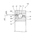
図1は本発明の実施形態を説明するための図で、転がり軸受の一部断面図である。ここでは転がり軸受として工作機械の主軸等、高速回転する装置に用いられるアンギュラ玉軸受を用いて説明する。
Hereinafter, embodiments of the present invention will be described in detail with reference to the drawings.
FIG. 1 is a view for explaining an embodiment of the present invention and is a partial sectional view of a rolling bearing. Here, an angular ball bearing used in a device that rotates at high speed, such as a spindle of a machine tool, will be described as a rolling bearing.
アンギュラ玉軸受100は、内周面に外輪軌道面11を有する外輪13と、外周面に内輪軌道面15を有する内輪17と、複数の玉(転動体)19と、複数のポケット21を有する保持器(転がり軸受用保持器)23と、を備える。
The angular ball bearing 100 has an
複数の玉19は、外輪軌道面11及び内輪軌道面15との間に接触角αを有して転動自在に配置される。保持器23は、複数の転動体19をポケット21内で転動自在に保持する。
The plurality of
保持器23は、保持器外径面の軸方向両端に、径方向外側へ突出する複数の被案内部25A,25Bが形成される。各被案内部25A,25Bは、それぞれ周方向に沿って等間隔で、しかも双方が同じ周位置に配置される。
The
本構成のアンギュラ玉軸受100は、軸方向の一端側(図1における左側)の被案内部25Aの案内面27が、外輪13の外輪軌道面11に対して反カウンターボア側の外輪内周面29に案内される外輪案内方式である。
In the angular ball bearing 100 of this configuration, the
<保持器の基本形状>
保持器23のポケット21は、内周面が保持器径方向に沿った円筒面であり、その円筒状の内周面は、所定の表面性状にされている。この表面性状を形成する微小な凹部には、潤滑剤であるグリースが保持され、ポケット21の転動体19との動滑性を向上させている。なお、ポケット21の内周面の表面性状については、後に詳述する。
<Basic shape of cage>
The
保持器23は、合成樹脂を含む材料を用いた射出成形品である。保持器23に使用可能な合成樹脂としては、例えば、PPS(ポリフェニレンサルファイド)、PPS−CF(カーボン繊維強化ポリフェニレンサルファイド)等が挙げられる。その他にも、母材として、PA(ポリアミド)、PAI(ポリアミドイミド)、熱可塑性ポリイミド、PEEK(ポリエーテルエーテルケトン)が利用可能で、強化繊維として、カーボン繊維、ガラス繊維、アラミド繊維等の有機繊維が利用可能である。
The
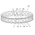
図2は保持器23の外観斜視図、図3は図2に示す保持器の一部拡大斜視図である。各被案内部25A,25Bは、径方向外側へ突出して外輪内周面29(図1参照)に摺接可能に形成される案内面27と、案内面27の縁部に形成された面取り部31とを有する。本構成の面取り部31は、案内面27の軸方向及び周方向の縁部である、周囲エッジの全周にわたって設けられる。
2 is an external perspective view of the
更に、被案内部25Aの案内面27の周方向中央部には、案内面27の径方向高さから窪んで、軸方向に沿った溝部33Aが形成される。同様に、被案内部25Bの案内面27の周方向中央部にも、案内面27の径方向高さから窪んで、軸方向に沿った溝部33Bが形成される。溝部33A,33Bの周方向の断面形状は、図示例の円弧形状の他、三角形状、矩形状、台形状等であってもよい。
Further, a
同じ周位置に配置される一組の被案内部25A,25Bは、軸方向と平行な一本の直線上に、それぞれの溝部33A,33Bが配置される。保持器23の外径面には、周方向の位相を一致させた一組の溝部33A,33Bが、周方向に沿って複数組配置される。
In the set of guided
また、周方向に隣接する被案内部25A,25Aとの間、及び、被案内部25B,25Bとの間は、案内面27より径方向高さが低い外径溝35A,35Bとされている。各外径溝35A,35Bは、それぞれ潤滑剤の排出溝として機能する。
Further,
図4は図3に示す保持器23のP1−P1線の拡大断面図である。案内面27の軸方向の縁部に形成された面取り部31は、曲率半径が0.2mm以上の曲面を有する。
4 is an enlarged cross-sectional view taken along line P1-P1 of the
一般に、軸受内に配置された保持器23は、図1に示すように、案内面27と外輪内周面29との間の案内すきまΔG/2と、ポケットすきまとの範囲で移動自在となる。そのため、保持器23は、軸線から傾斜して案内面27の周囲エッジが外輪13に偏当たりする場合がある。偏当たりが生じると、保持器23が摩耗して、寿命の低下や振動の劣化等の異常が生じる。この場合の保持器23の摩耗は、案内面27の周囲エッジから進行することが殆どである。しかし、本構成の保持器23によれば、案内面27の周囲エッジが、角部を滑らかにした面取り部31にされるため、摩耗が進行しにくくなる。
Generally, as shown in FIG. 1, the
一般に、外輪案内方式のアンギュラ玉軸受100においては、図1に示す外輪13の外輪内周面29と外輪軌道面11との境界の軌道面エッジ11aに、保持器23が接触することがある。保持器23が軌道面エッジ11aに接触すると、前述のように、保持器23は軌道面エッジ11aとの接触部分から摩耗が進行する。そこで、本構成の保持器23は、図1,図4に示すように、軌道面エッジ11aに接触しないように、外輪13の外輪軌道面11の軸方向縁部である軌道面エッジ11aとの対面領域に、径方向内側に窪むエッジ逃し部37を設けてある。
Generally, in the outer ball guide type angular ball bearing 100, the
エッジ逃し部37は、図3に示す被案内部25Aと25Bとの間の領域に相当し、案内面27の径方向高さから一段低く形成される。この段差によって、保持器23が傾斜した場合でも、軌道面エッジ11aが保持器23に接触することがなくなり、軌道面エッジ11aとの接触による保持器23の摩耗を未然に防止できる。
The
また、案内面27と面取り部31には、微小凹凸形状の表面性状が形成される。この微小凹凸形状の凹部にグリース等の潤滑剤が溜まることで、外輪13との接触時における接触抵抗が軽減され、摩耗の進行が抑制される。この表面性状を形成するためには、案内面27と面取り部31とを滑らかに接続する必要がある。
Further, the
図5(A)〜(C)は、面取り部31の形状を模式的に示す説明図である。図5(A)に示すように、面取り部31は、曲率半径rが0.2mm以上の曲面である。これにより、案内面27の周囲エッジが立つことがなく、案内面27と曲面とが滑らかに接続される。
5A to 5C are explanatory views schematically showing the shape of the chamfered
また、図5(B)に示すように、面取り部31の曲率半径rの中心を案内面27に近づけることで、面取り部31の曲面の接線方向と案内面27とを交差させ、案内面27の縁部27aに、面取り部31を接線方向に接続した構成であってもよい。縁部27aにおいて接続される曲面の接線方向と、案内面27との成す角θは、20°以下(0°<θ≦20°)とすることが好ましい。
Further, as shown in FIG. 5B, the tangential direction of the curved surface of the chamfered
更に、面取り部31は、図5(C)に示すように、保持器23の軸断面において、案内面27との成す角θが20°以下(0°<θ≦20°)の傾斜面であってもよい。この場合、保持器23に負荷される面圧を軽減し、打痕の発生を防止し、摩耗の進行を抑制できる。
Further, as shown in FIG. 5C, the chamfered
上記の面取り部31の形状は一例であって、これらに限らず任意の形状にできる。望ましくは、面取り部31を曲面形状(R形状)とし、曲面の接線と案内面27とが滑らかに接続される形状とするのがよい。
The shape of the chamfered
図1に示すように、外輪13の外輪内周面29と保持器23の案内面27との間の径方向の案内すきまΔG/2は、高速回転時における保持器音の発生、非同期振れNRRO、動トルク等に及ぼす影響が大きい。案内すきまΔG/2を外輪内周面29の案内径φGの0.2%〜0.8%に設定することで、高速回転時の軸受のNRROおよび動トルクを低減できる。
As shown in FIG. 1, the radial guide clearance ΔG / 2 between the outer ring inner
外輪案内保持器の場合、回転時に作用する遠心力と熱膨張により案内径φGが変化する。初期案内すきまが小さいと、回転時の案内すきまが0になり、トルクの増大や温度上昇、破損、異音が発生する虞がある。そのため、案内すきまΔG/2を案内径φGの0.2%以上にするのがよい。 In the case of an outer ring guide retainer, the guide diameter φG changes due to centrifugal force and thermal expansion acting during rotation. If the initial guide clearance is small, the guide clearance during rotation becomes zero, and there is a risk of increased torque, temperature rise, breakage, and abnormal noise. Therefore, it is preferable that the guide clearance ΔG / 2 is 0.2% or more of the guide diameter φG.
また、軸受回転時における保持器23の旋回する回転径は、案内すきまΔG/2で決定されるため、案内面の接触荷重は、案内すきまΔG/2に比例して大きくなる。更に、案内すきまΔG/2が過大の場合、保持器23が軸受内部で振動して保持器音が発生する要因となる。これらの理由より、案内すきまΔG/2は、案内径φGの0.8%より小さくするのがよい。
Further, since the rotation diameter of the
案内すきまΔG/2が案内径φGの0.8%以下に設定された保持器23は、軸受に組み込んでグリース潤滑で使用した場合、グリースの排出が妨げられる。このような保持器23は、慣らし運転に長時間を要するため、不良品となる。この慣らし運転時間は、外径溝35A,35Bの領域に保持器23のポケット21を含めることで、換言すれば、ポケット21の軸受軸方向の側方に外径溝35A,35Bを設けることで短縮できる。
When the
オイルエア潤滑の場合も同様であり、案内すきまが小さすぎると、オイルの排出性が悪くなり、異常な温度上昇や焼き付きの原因となる。なお、案内すきまが大きい場合には、グリースの排出が妨げられることはなく、外径溝を設けなくてもよい。 The same applies to the case of Oh Iruea lubrication, and guide the gap is too small, the discharge of oil is poor, cause of abnormal temperature rise and seizure. When the guide clearance is large, the grease discharge is not hindered and the outer diameter groove does not have to be provided.
また、図4に示すように、案内面27の案内幅L(面取り部31を除くストレート部の幅)を小さくすることで、保持器23の回転抵抗のトルクを低減できる。ただし、案内幅Lが0.5mm未満の場合には、外輪内周面29との接触面圧が高くなる。その場合、磨耗が進行して、軸受の耐久性が低下する。このため、案内面27の案内幅Lは0.5mm以上にする必要がある。
Moreover, as shown in FIG. 4, the torque of the rotational resistance of the
また、外輪13の軸方向幅をB(図1参照)としたとき、保持器23の幅H(図4参照)は、空間容積の確保と軽量化の観点からH/B≦0.95とするのがよく、更に、保持器23の後述するポケット開口部における最小肉厚t(図6(B)参照)を確保するため、0.4≦H/Bとするのが望ましい(0.4≦H/B≦0.95)。
Further, when the axial width of the
<保持器の成形用金型>
次に、保持器23を射出成形する成形用金型について説明する。
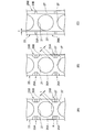
上記した合成樹脂製の保持器23は、成形用金型により一体に射出成形される。図6(A)は、保持器外径面の拡大図である。図6(B)は、成形用金型を模式的に示した図6(A)のP2−P2線における断面図である。図6(B)には、保持器23の外径部を成形する外側金型41と、保持器23のポケット21を成形するスライドコア43とを示す。成形用金型は、これらの金型部材の他に保持器23の内径面を形成する内側金型等を備えるが、ここではその説明を省略する。
<Mold for molding cage>
Next, a molding die for injection molding the
The above-mentioned
図6(B)に示す成形用金型は、アキシアルドロー方式の金型である。外側金型41及びスライドコア43は、保持器23の周方向に沿って複数個が配置され、それぞれ径方向に移動自在である。被案内部25A,25A(25B,25B)の溝部33A(33B)の周位置は、隣接する外側金型とのパーティングラインとなる。
Molding die shown in FIG. 6 (B) is a mold of the axial draw method. A plurality of
図6(A),(B)に示すように、保持器23は、被案内部25A,25B、外径溝35A,35B、及びエッジ逃し部37を含む外径面が、外側金型41より成形される。また、ポケット21が、スライドコア43により成形される。後述するように、スライドコア43の表面に形成された所定の表面性状は、保持器23のポケット21の内周面に転写される。
As shown in FIGS. 6A and 6B, the
スライドコア43に設けられる所定の表面性状を有した加工面(シボ加工面)は、ショットピーニング等のショット加工、放電加工、エッチング、ウォータージェット、レーザ加工等のいずれかにより形成できる。なお、上記加工面は、上記加工方法を単独、又は組み合わせた加工で形成してもよく、上記以外の加工方法で形成してもよい。
A processed surface (textured surface) having a predetermined surface property provided on the
ところで、被案内部25A,25Bの角部Kとポケット21(内周面)とは接近しているため、この繋ぎ部を成形する外側金型41の凸部41aは、肉厚tが薄くなる。このように、金型に肉厚tの薄い部分があると、金型強度が不足して、金型に変形や割れ等が生じる虞がある。
By the way, since the corner | angular part K and the pocket 21 (inner peripheral surface) of the to-
そのため、図6(A)に示すように、被案内部25A,25Bの角部Kの円周方向位相を、ポケット21の軸方向最大径となる周方向位置Pk1とポケット21の周方向端部となる周方向位置Pk2との間の領域Cに設ける。そして、被案内部25A,25Bの角部Kとポケット21の内周面との最小距離(肉厚t)を0.5mm以上にする。これにより、金型が特に薄くなる部分をなくし、金型強度不足による障害を防止している。
Therefore, as shown in FIG. 6 (A), the guided
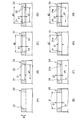
図7は、薄肉部を補正した金型により成形される他の保持器の外径面を示す一部拡大図である。図7(A)は、被案内部25A,25Bの角部Kを、曲面状の面取り形状にすることで金型の肉厚tを大きくしている。
FIG. 7 is a partially enlarged view showing an outer diameter surface of another cage formed by a mold in which a thin portion is corrected. FIG. 7 (A) guided
図7(B)は、被案内部25A,25Bの角部Kを斜めにカットすることで金型の肉厚tを大きくしている。
FIG. 7 (B) by increasing the thickness t of the metal mold by cutting guided
また、図7(C)は、通常の大きさの案内すきまΔG/2(例えば、外輪内周面29の案内径φGの0.8%以上)を有し、外径溝35A,35Bを設ける必要がない保持器23である(図12参照)。この保持器23は、被案内部26A,26Bをポケット21から軸方向に離間して設けることで、被案内部26A,26Bとポケット21との最小距離(肉厚t)を0.5mm以上としている。
Further, FIG. 7 (C) guides the normal size gap .DELTA.G / 2 (e.g., 0.8% or more of draft inside diameter φG of the outer ring inner peripheral surface 29) has an
いずれの場合にも、金型の強度不足による障害を防止できる。 In any case, it is possible to prevent failure due to insufficient strength of the mold.
<ポケット内周面の表面性状>
上記の成形用金型は、保持器23にポケット21を形成する金型(スライドコア43)の表面が、所定の表面性状を有する。すなわち、スライドコア43の金型表面は、通常よりも大きな所定の表面粗さの加工面とされている。この加工面の表面形状は、射出成形される保持器23のポケット21の内周面に転写される。これにより、ポケット内周面はシボ加工面となる。
<Surface properties of pocket inner peripheral surface>
In the molding die described above, the surface of the mold (slide core 43) that forms the
保持器23のポケット21の内周面に、金型表面の加工面の形状が転写付与された形状転写面の表面粗さは、JIS B0601に規定される算術平均粗さRaを1.0〜9.8μmに、最大高さRtを10.1〜102.9μmに設定される(Ra,Rtの数値については、必要に応じて特開2014−95469号公報を参照されたい)。
The surface roughness of the shape transfer surface obtained by transferring the shape of the processed surface of the mold surface to the inner peripheral surface of the
これにより、所定の表面粗さを形成する凹部に潤滑剤であるグリースが保持され、この凹部からポケット21の内周面と転動体19との接触界面(図1参照)にグリースが供給される。したがって、軸受の高速回転化によって潤滑条件が厳しくなった場合であっても、接触界面に油膜が途切れることがない。このため、急激な温度上昇や焼き付きを長期にわたり抑制できる。
As a result, the grease as the lubricant is held in the recess that forms the predetermined surface roughness, and the grease is supplied from this recess to the contact interface (see FIG. 1) between the inner peripheral surface of the
また、加工面の表面形状は、ランダムな微細凹凸形状の他、ディンプル等の凹形状や微細な溝であってもよい。 Further, the surface shape of the processed surface may be a concave shape such as a dimple or a fine groove in addition to a random fine uneven shape.
保持器23は、耐摩耗性や機械的強度の向上のために、ガラス繊維や炭素繊維等の充填材を樹脂材料に混入させて補強してもよい。その場合、保持器23の案内面27と外輪13の外輪内周面29との接触界面で、充填材を含む摩耗粉が生成されることがある。この摩耗粉は、軸受回転時に異物として作用して、切削摩耗が増大する虞がある。しかし、本構成によれば、上記の表面性状の微小凹凸形状により、摩耗粉が接触界面から容易に排除される。これにより、保持器23の耐摩耗性が向上する。
The
算術平均粗さRaが1.0μm未満の範囲では、表面粗さを形成する凹部のグリース保持量が少なくなり、保持器23のポケット21の内周面と転動体19との接触界面に対するグリース供給が不十分となる。また、算術平均粗さRaが9.8μmを超えると、その粗さ自体が、高精度の高速回転が要求される工作機械の主軸用軸受の回転精度に悪影響を及ぼす可能性がある。
When the arithmetic average roughness Ra is less than 1.0 μm, the amount of grease retained in the recesses that form the surface roughness is reduced, and the grease is supplied to the contact interface between the inner peripheral surface of the
ポケット21の内周面に付与される表面粗さは、最大高さRtを10.1〜102.9μmの範囲にされている。このように最大高さRtを上記範囲に定めることで、特異的に高い山部や低い谷部の発生が抑えられ、摺動時の振動が抑制されて軸受性能を向上できる。
The surface roughness applied to the inner peripheral surface of the
上記の通り、ポケット21の内周面の表面性状は、保持器23の射出成形時にスライドコア43の表面の形状転写によって付与される。このため、ポケット21の内周面には、均一、且つ再現性の高い状態で表面層(形状転写層)が形成され、保持器23の耐摩耗性をより確実に向上できる。
As described above, the surface texture of the inner peripheral surface of the
<ポケットの成形>
外輪案内形式の保持器23のポケット21は、通常、径方向に沿った円筒形状となっている。このため、上記した表面性状となる表面形状を設けたスライドコア43を径方向外側に抜き取る際、ポケット21の内周面に付与した表面形状がせん断により崩れる虞がある。
<Pocket molding>
The
表1は、直径95mmの円筒形状部をショット法により算術平均粗さRa3μmに加工した金型を用い、保持器23を成形して、長さ16mmの距離を表面形状転写面と平行に引抜いたときの、PPS-CF樹脂の表面形状の状態を顕微鏡で観察した結果を示す。
Table 1 shows that a
引抜き長さが3.5mm以下では、金型から転写させた表面形状が異常なく残っている。引抜き距離が3.5〜4.5mmでは80%以上、金型から転写させた表面形状が残っている。しかし、引抜き距離が4.5mm以上では、金型とのせん断で表面が削り取られており、金型から転写された所定の表面粗さの表面形状が破壊された状態となっている。したがって、金型のせん断方向への引抜き距離に相当する、ポケット21の内周面の長さD(図8参照)、つまり、ポケット21の円筒面の保持器径方向の厚みは、4.5mm以下、より望ましくは3.5mm以下とする必要がある。
When the drawing length is 3.5 mm or less, the surface shape transferred from the mold remains without abnormality. When the drawing distance is 3.5 to 4.5 mm, 80% or more of the surface shape transferred from the mold remains. However, when the drawing distance is 4.5 mm or more, the surface is scraped off by shearing with the mold, and the surface shape having a predetermined surface roughness transferred from the mold is broken. Therefore, the length D (see FIG. 8 ) of the inner peripheral surface of the

ポケット21の内周面の径方向長さDが大きく、上記の引抜き距離が大きい場合や、付与される表面形状が大きく、引抜きにより表面形状が損傷し、金型が磨耗して寿命が低下する場合がある。そのような場合には、図8(A)に示す前述した形状に代えて、図8(B)に示すように、転動体19と接触しない保持器23の径方向内側のポケット径d1を小さくすればよい。又は、図8(C)に示すように、転動体19と接触しない保持器23の径方向外側のポケット径d2を大きくすればよい。
When the radial length D of the inner peripheral surface of the
保持器内径側や保持器外径側に、ポケット21の内径を拡縮する段付き部22を設けることにより、実質的な引抜き距離(接触しながら摺動する距離)を短縮でき、スライドコア43から転写される表面形状の損傷を抑制できる。
By providing the stepped
また、図8(D)に示すように、保持器23の径方向内側のポケット径d1を小さくし、且つ径方向外側のポケット径d2を大きくしてもよい。この場合、引抜き距離をより短縮できる。
Further, as shown in FIG. 8 (D), to reduce the radially inner pocket diameter d1 of the
また、図8(E)に示すように、ポケット21の内周面全体をθ=0.5°以上のテーパ角で、内周側から外周側に向けて拡径するテーパ面にしてもよい。その場合、スライドコア43を引抜く際に、せん断が発生しなくなり、ポケットの表面形状を保護できる。また、スライドコアの寿命を向上できる。
Further, as shown in FIG. 8 (E), the entire inner peripheral surface of the
図8(F)は径方向内側のポケット径d1を小さくし、且つテーパ面21aとしている。図8(G)は径方向外側のポケット径d2を大きくし、且つテーパ面21aとしている。図8(H)は径方向内側のポケット径d1を小さく、径方向外側のポケット径d2を大きく形成すると共にテーパ面21aとしている。このように、ポケット21の内周面の形状を、引抜き距離が実質的に短縮する形状にすることで、スライドコア43の引抜き時における樹脂の損傷が抑制され、金型寿命を延長することが可能になる。
Figure 8 (F) is to reduce the pocket diameter d1 of the radially inner and has a tapered
上記したように、ポケット部には、スライドコア43を引抜く際にせん断力が発生する。そのため、保持器23の外径部を成形する外側金型41の寿命と、保持器23のポケット21を成形するスライドコア43の寿命とが、大きく異なってしまうことが考えられる。しかし、本金型構成によれば、形状が複雑で高価な外側金型41は、そのまま継続して利用して、スライドコア43は、外側金型41とは別体に構成されている。そのため、ピン形状の安価なスライドコア43のみを交換可能にでき、金型のランニングコストを低減できる。
As described above, a shearing force is generated in the pocket portion when the
なお、上記の案内面27と面取り部31の微小凹凸形状は、ポケット21の内周面と同様に、算術平均粗さRa=1.0〜9.8μm、最大高さRt=10.1〜102.9μmの範囲にしてもよい。また、この微小凹凸形状は、スライドコア43の表面加工方法と同様に、金型表面に施すことで得られる。
In addition, the micro unevenness | corrugation shape of said
<保持器表面のスキン層>
保持器23を射出成形により成形する際には、高温の樹脂が温度の低い金型に接触して急冷される。そのため、金型付近の部分となる保持器23の表面部分に、スキン層と呼ばれる非晶質層が形成される。また、成形時の樹脂が樹脂表面に並行に流れるため、成形後の樹脂内部の表層部における強化繊維(CF(カーボンファイバー)、GF(グラスファイバー)、AF(アラミドファイバー)等)も表面に並行に配列される。
<Skin layer on cage surface>
When the
非晶質層は、樹脂材料がPPS(ポリフェニレンサルファイド樹脂)やPEEK(ポリエーテルエーテルケトン樹脂)等である場合には、表面近傍まで結晶化するため、非常に薄い0.1〜10μm程度の厚さとなる。樹脂材料がナイロン等のポリアミド樹脂である場合には、非晶質層が形成されやすく10〜30μm程度の厚さとなる。 When the resin material is PPS (polyphenylene sulfide resin), PEEK (polyether ether ketone resin), etc., the amorphous layer crystallizes to the vicinity of the surface. Therefore, the amorphous layer has a very thin thickness of about 0.1 to 10 μm. It becomes. When the resin material is a polyamide resin such as nylon, an amorphous layer is easily formed and the thickness is about 10 to 30 μm.
強化繊維は、保持器と摺動される外輪、内輪、及び転動体の鋼材に対して攻撃性が強い。特に、強化繊維を含む樹脂材料をバリ取りのためバレル加工や切削加工を施した表面を摺動面とした場合は、強化繊維が樹脂表面に対して交差する方向に析出する。そのため、強化繊維は、端部が鋭角になり、外輪、内輪、及び転動体を傷付けたり、摩耗の原因となる。更に、強化繊維が保持器表層に現れるため、強化繊維が脱落し、軸受の寿命低下に繋がる虞がある。 Reinforcing fibers are highly aggressive against the outer ring, the inner ring, and the rolling member steel material that slide with the cage. In particular, when the surface subjected to barrel processing or cutting for deburring a resin material containing reinforcing fibers is used as a sliding surface, the reinforcing fibers are deposited in a direction intersecting the resin surface. Therefore, the end of the reinforcing fiber has an acute angle, which damages the outer ring, the inner ring, and the rolling element, or causes wear. Furthermore, since the reinforcing fibers appear on the surface of the cage, the reinforcing fibers may fall off, leading to a reduction in bearing life.
そのため、保持器表層にスキン層を持つことにより、強化繊維の脱落及び析出した強化繊維による相手部材への攻撃を抑制できる。 Therefore, by having a skin layer on the cage surface layer, it is possible to suppress the detachment of the reinforcing fibers and the attack on the mating member by the precipitated reinforcing fibers.
更に、保持器表面に強化繊維が並行に配列されるため、スキン層が摩耗等で除去された後も強化繊維の端部が外輪、内輪、及び転動体に対して鋭角に当たらない。これにより、相手部材の摩耗を抑制できる。 Further, since the reinforcing fibers are arranged in parallel on the surface of the cage, the end portions of the reinforcing fibers do not hit the outer ring, the inner ring, and the rolling element even after the skin layer is removed by abrasion or the like. Thereby, wear of the mating member can be suppressed.
このスキン層は、特開2001−227548に示すように、表面から30μm以下に存在するのが望ましい。また、上述したように、表層部にスキン層が存在することが必要であるため、保持器表層に、保持器表面からの厚みが0.1〜30μmである、強化繊維を含まない非晶質層が形成されていることが望ましい。 As shown in JP-A-2001-227548, this skin layer is preferably present at 30 μm or less from the surface. Further, as described above, since it is necessary for the skin layer to be present in the surface layer portion, the cage surface layer has a thickness from the cage surface of 0.1 to 30 μm and does not contain reinforcing fibers. It is desirable that a layer is formed.
<他の構成例>
次に、上記した保持器23の他の構成例について説明する。
(第1変形例)
図9に他の構成の保持器23Aを備えたアンギュラ玉軸受110の一部断面図、図10に保持器23Aの外観斜視図を示す。以下の説明では、図1に示す部材と同一の部材に対しては同一の符号を付与することで、その部材の説明は省略又は簡単化する。
<Other configuration examples>
Next, another configuration example of the above-described
(First modification)
FIG. 9 shows a partial cross-sectional view of an
本変形例の保持器23Aは、軸方向の一端側のみに被案内部25Aを設けてあり、他端側の被案内部は省略されている。保持器23Aは、被案内部25Aが外輪13の外輪内周面29に案内される。その際、保持器23Aにエッジ逃し部37が設けられたことにより、外輪の軌道面エッジ11aが保持器23Aに接触することはない。また、保持器23Aのポケット21の内周面は、前述した所定の表面性状となっている。この表面形状は、金型(スライドコア43)の加工面が転写されて形成されたものである。
The
本変形例によれば、保持器23Aをよりシンプルな構造にできる。また、所定の表面粗さを形成するポケット21の微小な凹部に、潤滑剤であるグリースが保持されて、この凹部からポケット21の内周面と転動体19との接触界面にグリースが供給される。よって、保持器23Aの耐久性が高められる。
According to this modified example, the
(第2変形例)
図11に他の構成の保持器23Bを備えたアンギュラ玉軸受120の一部断面図を示す。本変形例の保持器23Bは、被案内部25A,25Bのいずれも備えておらず、保持器23Bのポケット21の内周面には、前述した所定の表面性状が、金型から転写されて形成されている。それ以外は、前述の第1変形例の保持器23Aと同様である。
(Second modification)
FIG. 11 shows a partial cross-sectional view of an
本変形例によれば、保持器23Bをよりシンプルな構造にできる。また、所定の表面性状を形成する微小な凹部に、潤滑剤であるグリースが保持され、この凹部からポケット21の内周面と転動体19との接触界面にグリースが供給される。よって、保持器23Bの耐久性が高められる。
According to this modification, the
(第3変形例)
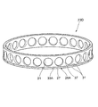
図12に他の構成の保持器23Cの外観斜視図を示す。保持器23Cは、前述した所定の表面粗さを有する表面形状がスライドコア43から転写されたポケット21を有し、且つ、保持器外径部の軸方向両端に半径方向外側へ突出する被案内部26A,26Bを有する。各被案内部26A,26Bには、それぞれ軸方向に沿って案内面27の径方向高さから窪んだ溝部33A,33Bが複数形成される。
(Third Modification)
FIG. 12 shows an external perspective view of a
本変形例の保持器23Cは、図3に示す保持器23の場合と同様に、一組の溝部33A,33Bが同じ周位置に配置される。また、案内面27の被案内部26A,26Bの軸方向の縁部には、面取り部31,31が形成される。ただし、図3に示すような外径溝35A,35Bは存在せず、案内面27が周方向に連続して配置される。
As in the case of the
本変形例の保持器23Cによれば、案内面27の周囲エッジが面取り部31にされ、摩耗が進行しにくくなる。また、径方向内側に窪むエッジ逃し部37によって、軌道面エッジ11a(図1参照)が保持器23に接触することがなくなり、接触による摩耗を未然に防止できる。更に、ポケット21の内周面が、所定の表面性状を有する形状転写面となることで、耐摩耗性を向上でき、保持器23Cの耐久性が高められる。
According to the
(第4変形例)
図13に他の構成の保持器23Dの外観斜視図を示す。保持器23Dは、保持器外径部の軸方向一端のみに半径方向外側へ突出する被案内部26Aを有すること以外は、前述の第3変形例の保持器23Cと同様である。
(Fourth modification)
FIG. 13 shows an external perspective view of a
本変形例の保持器23Dによれば、保持器23Dをシンプルな構造にでき、ポケット21の内周面に、前述した所定の表面性状を有する表面形状が、金型から転写されて形成されることで、ポケット21の内周面と転動体19との接触界面にグリースが供給される。よって、保持器23Dの耐久性を高めることができる。
According to the
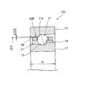
以上説明したように、本構成の転がり軸受としては、アンギュラ玉軸受に限定されるものではなく、円筒ころ軸受等、他の種類の転がり軸受であってもよい。例えば、図14に示すように、保持器23Eが、ポケット21に形成されたテーパ孔21bに転動自在に配置される転動体19によって案内される転動体案内方式の転がり軸受であってもよい。
As described above, the rolling bearing of this configuration is not limited to the angular ball bearing, and may be another type of rolling bearing such as a cylindrical roller bearing. For example, as illustrated in FIG. 14 , the
本発明は上記の実施形態に限定されるものではなく、実施形態の各構成を相互に組み合わせることや、明細書の記載、並びに周知の技術に基づいて、当業者が変更、応用することも本発明の予定するところであり、保護を求める範囲に含まれる。 The present invention is not limited to the above-described embodiments, and the configurations of the embodiments may be combined with each other, or may be modified or applied by those skilled in the art based on the description of the specification and well-known techniques. The invention is intended and is within the scope of seeking protection.
11 外輪軌道面
13 外輪
15 内輪軌道面
17 内輪
19 転動体
21 ポケット
21a テーパ面
22 段付き部
23,23A,23B,23C,23D,23E 保持器(転がり軸受用保持器)
41 外側金型
43 スライドコア
100,110,120 アンギュラ玉軸受(転がり軸受)
D 内周面の径方向長さ(円筒面の径方向厚み)
11 outer
41
D Radial length of inner peripheral surface (radial thickness of cylindrical surface)
Priority Applications (6)
| Application Number | Priority Date | Filing Date | Title |
|---|---|---|---|
| US15/548,487 US10422381B2 (en) | 2015-02-04 | 2016-02-04 | Rolling bearing retainer, rolling bearing, and method for manufacturing rolling bearing retainer |
| PCT/JP2016/053351 WO2016125855A1 (en) | 2015-02-04 | 2016-02-04 | Rolling bearing retainer, rolling bearing, and method for manufacturing rolling bearing retainer |
| KR1020177021769A KR102018966B1 (en) | 2015-02-04 | 2016-02-04 | Rolling bearing retainer, rolling bearing, and method for manufacturing rolling bearing retainer |
| EP16746686.1A EP3255293B1 (en) | 2015-02-04 | 2016-02-04 | Rolling bearing retainer, rolling bearing, and method for manufacturing rolling bearing retainer |
| TW105103847A TWI592586B (en) | 2015-02-04 | 2016-02-04 | A cage for a rolling bearing and a rolling bearing, and a method for manufacturing the cage for a rolling bearing |
| CN201680008792.4A CN107250582B (en) | 2015-02-04 | 2016-02-04 | The manufacturing method of retainer for rolling bearing and rolling bearing and retainer for rolling bearing |
Applications Claiming Priority (2)
| Application Number | Priority Date | Filing Date | Title |
|---|---|---|---|
| JP2015020737 | 2015-02-04 | ||
| JP2015020737 | 2015-02-04 |
Publications (3)
| Publication Number | Publication Date |
|---|---|
| JP2016145644A JP2016145644A (en) | 2016-08-12 |
| JP2016145644A5 true JP2016145644A5 (en) | 2019-03-14 |
| JP6686483B2 JP6686483B2 (en) | 2020-04-22 |
Family
ID=56685419
Family Applications (1)
| Application Number | Title | Priority Date | Filing Date |
|---|---|---|---|
| JP2016017837A Active JP6686483B2 (en) | 2015-02-04 | 2016-02-02 | Rolling bearing cage, rolling bearing, and rolling bearing cage manufacturing method |
Country Status (1)
| Country | Link |
|---|---|
| JP (1) | JP6686483B2 (en) |
Families Citing this family (4)
| Publication number | Priority date | Publication date | Assignee | Title |
|---|---|---|---|---|
| JP6880835B2 (en) * | 2017-03-03 | 2021-06-02 | 三菱ケミカル株式会社 | Molding mold and resin molded product manufacturing method |
| JP7430983B2 (en) | 2019-03-18 | 2024-02-14 | Ntn株式会社 | Angular contact ball bearings and cages for angular contact ball bearings |
| JP2022169195A (en) | 2021-04-27 | 2022-11-09 | Ntn株式会社 | Angular ball bearing |
| CN114922901A (en) * | 2022-05-13 | 2022-08-19 | 常熟长城轴承有限公司 | Engineering plastic injection molding high-speed angular contact ball bearing retainer and lubricating method thereof |
Family Cites Families (7)
| Publication number | Priority date | Publication date | Assignee | Title |
|---|---|---|---|---|
| JP3952107B2 (en) * | 1998-08-13 | 2007-08-01 | 日本精工株式会社 | Split type cage for rolling bearings |
| JP2001227548A (en) * | 2000-02-17 | 2001-08-24 | Nsk Ltd | Cage for rolling bearing |
| JP2002323048A (en) * | 2000-10-27 | 2002-11-08 | Nsk Ltd | Bearing device and main spindle of machine tool |
| JP2005256893A (en) * | 2004-03-10 | 2005-09-22 | Nsk Ltd | Rolling bearing for turbo charger |
| DE202012005052U1 (en) * | 2012-05-23 | 2012-07-05 | Imo Holding Gmbh | Rolling bearing cage with inserts |
| JP5929544B2 (en) * | 2012-06-21 | 2016-06-08 | 日本精工株式会社 | Rolling bearings and spindles for machine tools |
| JP2014095469A (en) * | 2012-10-09 | 2014-05-22 | Nsk Ltd | Rolling bearing |
-
2016
- 2016-02-02 JP JP2016017837A patent/JP6686483B2/en active Active
Similar Documents
| Publication | Publication Date | Title |
|---|---|---|
| KR102018966B1 (en) | Rolling bearing retainer, rolling bearing, and method for manufacturing rolling bearing retainer | |
| WO2014163177A1 (en) | Tapered roller bearing-use resin made cage and tapered roller bearing provided with such cage | |
| JP5604896B2 (en) | Angular contact ball bearings | |
| JP6686483B2 (en) | Rolling bearing cage, rolling bearing, and rolling bearing cage manufacturing method | |
| JP2016145644A5 (en) | ||
| KR102013084B1 (en) | Method of manufacturing conical roller bearings and conical roller bearings | |
| JP2014095469A (en) | Rolling bearing | |
| US10221891B2 (en) | Taper roller bearing | |
| WO2018084219A1 (en) | Retainer and rolling bearing with same | |
| JP6686482B2 (en) | Rolling bearing cage, rolling bearing, and rolling bearing cage manufacturing method | |
| US10539184B2 (en) | Taper roller bearing | |
| WO2016125855A1 (en) | Rolling bearing retainer, rolling bearing, and method for manufacturing rolling bearing retainer | |
| JP2014005846A (en) | Ball bearing and spindle device for machine tool | |
| JP2007147056A (en) | Cylindrical roller bearing | |
| US10138939B2 (en) | Taper Roller Bearing | |
| JP6529209B2 (en) | Angular contact ball bearings | |
| WO2015146811A1 (en) | Angular ball bearing | |
| US9115762B2 (en) | Rolling bearing | |
| US20170191528A1 (en) | Ball bearing cage | |
| US10215233B2 (en) | Taper roller bearing | |
| JP4387162B2 (en) | Cylindrical roller bearing | |
| US10408266B2 (en) | Cage for taper roller bearing and taper roller bearing | |
| JP2009257593A (en) | Cylindrical roller bearing | |
| JP2008093833A (en) | Mold for crown shape holder, manufacturing method of crown shape holder and rolling ball bearing | |
| JP2015094403A (en) | Roller bearing |