JP2016143753A - Heat pipe cooling device and elevator system equipped with the same - Google Patents
Heat pipe cooling device and elevator system equipped with the same Download PDFInfo
- Publication number
- JP2016143753A JP2016143753A JP2015018147A JP2015018147A JP2016143753A JP 2016143753 A JP2016143753 A JP 2016143753A JP 2015018147 A JP2015018147 A JP 2015018147A JP 2015018147 A JP2015018147 A JP 2015018147A JP 2016143753 A JP2016143753 A JP 2016143753A
- Authority
- JP
- Japan
- Prior art keywords
- temperature
- heat
- heat pipe
- working medium
- cooling device
- Prior art date
- Legal status (The legal status is an assumption and is not a legal conclusion. Google has not performed a legal analysis and makes no representation as to the accuracy of the status listed.)
- Granted
Links
Images
Classifications
-
- Y—GENERAL TAGGING OF NEW TECHNOLOGICAL DEVELOPMENTS; GENERAL TAGGING OF CROSS-SECTIONAL TECHNOLOGIES SPANNING OVER SEVERAL SECTIONS OF THE IPC; TECHNICAL SUBJECTS COVERED BY FORMER USPC CROSS-REFERENCE ART COLLECTIONS [XRACs] AND DIGESTS
- Y02—TECHNOLOGIES OR APPLICATIONS FOR MITIGATION OR ADAPTATION AGAINST CLIMATE CHANGE
- Y02B—CLIMATE CHANGE MITIGATION TECHNOLOGIES RELATED TO BUILDINGS, e.g. HOUSING, HOUSE APPLIANCES OR RELATED END-USER APPLICATIONS
- Y02B50/00—Energy efficient technologies in elevators, escalators and moving walkways, e.g. energy saving or recuperation technologies
Landscapes
- Elevator Control (AREA)
- Cooling Or The Like Of Electrical Apparatus (AREA)
- Cooling Or The Like Of Semiconductors Or Solid State Devices (AREA)
Abstract
Description
本発明は、ヒートパイプ式冷却装置及びこれを備えたエレベータシステムに関する。 The present invention relates to a heat pipe type cooling device and an elevator system including the same.
一般に、エレベータの制御装置には、主回路素子(以下、単に「主回路」ともいう。)と共に、この主回路素子を冷却するための放熱フィンを備えたヒートパイプが設けられており、主回路の起動・停止を繰り返すことにより、主回路駆動による発熱量とヒートパイプ放熱量とが均衡するところまで主回路素子の温度は上昇する。そして、エレベータの運転状況や設置環境により、主回路素子の許容温度を超えるおそれがあることから、放熱フィン近傍に冷却ファンを取付け、送風することで強制的に冷却するようになっている。この冷却ファンの制御であるが、現状では、主回路の起動中、および主回路停止後の一定時間、例えば起動停止後3分間、冷却ファンを駆動している。 In general, an elevator control device is provided with a main circuit element (hereinafter, also simply referred to as “main circuit”) and a heat pipe provided with heat radiation fins for cooling the main circuit element. By repeatedly starting and stopping, the temperature of the main circuit element rises to a point where the amount of heat generated by driving the main circuit and the amount of heat released from the heat pipe are balanced. And since there exists a possibility of exceeding the allowable temperature of a main circuit element by the driving | running state and installation environment of an elevator, a cooling fan is attached in the vicinity of a radiation fin, and it cools by forcing it. In this control of the cooling fan, at present, the cooling fan is driven during the start-up of the main circuit and for a fixed time after the main circuit is stopped, for example, 3 minutes after the start-up is stopped.
ヒートパイプ式冷却装置の従来例としては、特許文献1(特開平7−190655号公報)に記載されるものを挙げることができる。特許文献1には、水を作動液として用いたヒートパイプに感温素子を取り付け、外気温度またはヒートパイプ温度を検出し、この温度が設定値以下となったときにファンの回転速度を制御し、作動液の凍結を防止する技術が記載されている。 As a conventional example of the heat pipe type cooling device, one described in Patent Document 1 (Japanese Patent Laid-Open No. 7-190655) can be cited. In Patent Document 1, a temperature sensing element is attached to a heat pipe using water as a working fluid, the outside air temperature or the heat pipe temperature is detected, and the rotational speed of the fan is controlled when the temperature falls below a set value. A technique for preventing the working fluid from freezing is described.
主回路の起動中、および主回路停止後の一定時間、ヒートパイプ式冷却装置の冷却ファンを駆動するものでは、例えばエレベータが低温環境にあると、主回路素子の起動および停止からなる1運転当たりの温度変化の幅が比較的大きくなる場合があり、主回路素子の寿命サイクルを有効に活用できないという課題があった。すなわち、例えばエレベータが低温環境に設置されている場合、所定時間にわたるファン駆動により、作動媒体の温度が大きく低下するため、主回路素子の1運転当たりの温度変化の幅が大きくなってしまい、主回路素子の劣化を早める要因となる。 In the case of driving the cooling fan of the heat pipe type cooling device for a certain period of time after the main circuit is started and after the main circuit is stopped, for example, when the elevator is in a low temperature environment, In some cases, the temperature change width of the main circuit element is relatively large, and the life cycle of the main circuit element cannot be effectively utilized. That is, for example, when the elevator is installed in a low temperature environment, the temperature of the working medium is greatly reduced by driving the fan for a predetermined time, so that the width of the temperature change per operation of the main circuit element becomes large. It becomes a factor which accelerates deterioration of a circuit element.
また、ヒートパイプの特性から、ヒートパイプの温度が低下し過ぎると、ヒートパイプの冷却性能は低下する。冷却ファンがヒートパイプの温度によらず主回路の起動に応じて駆動するものである場合、エレベータが低温環境にあると、ヒートパイプの作動媒体が効率的に作動する温度範囲を大きく下回る。このような状態のヒートパイプを用いて次に主回路の運転をする際には、ヒートパイプの立ち上げ時間が長くなるため、冷却性能はしばらくの間、低下した状態にあり、冷却効率の低下を招くという課題があった。 In addition, due to the characteristics of the heat pipe, if the temperature of the heat pipe is excessively decreased, the cooling performance of the heat pipe is decreased. When the cooling fan is driven in accordance with the activation of the main circuit regardless of the temperature of the heat pipe, if the elevator is in a low temperature environment, the temperature range is greatly below the temperature range in which the working medium of the heat pipe operates efficiently. The next time the main circuit is operated using the heat pipe in such a state, since the start-up time of the heat pipe becomes longer, the cooling performance has been lowered for a while, and the cooling efficiency is lowered. There was a problem of inviting.
なお、特許文献1に記載のヒートパイプ式冷却装置においては、ファンを制御する際の設定温度は、基本的に作動液の凍結温度としている。 In the heat pipe type cooling device described in Patent Document 1, the set temperature for controlling the fan is basically the freezing temperature of the hydraulic fluid.
本発明の目的は、使用温度範囲が限られた被除熱対象物の温度変化の幅を小さくすると共に、冷却効率が高い温度範囲で使用することができるヒートパイプ式冷却装置を提供することにある。 An object of the present invention is to provide a heat pipe type cooling device that can be used in a temperature range with high cooling efficiency while reducing the temperature change range of a heat removal target with a limited use temperature range. is there.
本発明のヒートパイプ式冷却装置は、作動媒体を内封し、被除熱対象物からの熱により液体状態の作動媒体を蒸発させる吸熱部、及び、気体状態の作動媒体を凝縮させる放熱部を有するヒートパイプと、放熱部を強制対流により冷却する冷却ファンと、を備え、吸熱部における作動媒体の温度の検出又は推定が可能な温度検出部を有し、温度検出部における検出又は推定により得られた温度が、被除熱対象物の温度変化の幅を小さくするために設定された作動媒体の温度の下限値以上の所定温度以上であるときは、冷却ファンを駆動する。 The heat pipe type cooling device of the present invention includes a heat absorption part that encloses the working medium and evaporates the liquid working medium by heat from the heat removal target, and a heat radiating part that condenses the gaseous working medium. Having a temperature detection unit capable of detecting or estimating the temperature of the working medium in the heat absorption unit, and obtained by detection or estimation in the temperature detection unit. When the obtained temperature is equal to or higher than a predetermined temperature equal to or higher than the lower limit value of the temperature of the working medium set in order to reduce the temperature change width of the heat removal target, the cooling fan is driven.
本発明によれば、ヒートパイプ式冷却装置を用いて、使用温度範囲が限られた被除熱対象物の温度変化の幅を小さくすると共に、冷却効率が高い温度範囲でヒートパイプを使用することができる。 According to the present invention, using the heat pipe type cooling device, the width of the temperature change of the object to be removed with a limited operating temperature range is reduced, and the heat pipe is used in a temperature range where the cooling efficiency is high. Can do.
以下、本発明の実施形態に係るヒートパイプ式冷却装置について図面に基づいて説明する。 Hereinafter, the heat pipe type cooling device concerning the embodiment of the present invention is explained based on a drawing.
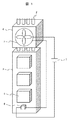
図1は、本発明のヒートパイプ式冷却装置の一例を示す概略構成図である。 FIG. 1 is a schematic configuration diagram showing an example of a heat pipe type cooling device of the present invention.
本図において、ヒートパイプ式冷却装置は、吸熱部及び放熱部4を有するヒートパイプ2を基本構成とする。ヒートパイプ2は、被除熱対象物1から熱伝導部材3を介して吸収した熱により内封した作動媒体(液体状態)が吸熱部で蒸発し、気体となった作動媒体が放熱部4で凝縮するものである。ここで、作動媒体の例としては、水、エタノール、メタノール等が挙げられる。作動媒体の種類を選択することにより、ヒートパイプ2として機能し得る温度範囲を設定することができる。
In this figure, the heat pipe type cooling device has a
ヒートパイプ2の吸熱部は、被除熱対象物1に付設された熱伝導部材3に挿入され、被除熱対象物1の熱を吸収する。ここで、被除熱対象物1は、例えば、エレベータの制御装置が有する主回路素子である。主回路素子は、IGBT等のパワー半導体を備えたインバータ等である。
The heat absorption part of the
一方、ヒートパイプ2の放熱部4は、放熱フィン(図示していない)を有し、冷却ファン5からの送風により冷却される。言い換えると、放熱部4においては、放熱フィンは、強制対流による空冷がなされ、作動媒体の凝縮熱が大気に放散される。
On the other hand, the
ヒートパイプ2の作動媒体の温度は、温度検出部6(例えばサーマルスイッチ)により検出する。この際、温度検出部6は、熱伝導部材3の温度又はヒートパイプ2の吸熱部の外表面温度を測定するが、これにより測定された温度から作動媒体の温度を推算する。なお、温度検出部6をヒートパイプ2の内部に配置することにより、作動媒体の温度にほぼ等しい温度を測定してもよい。言い換えると、温度検出部6は、ヒートパイプ2の吸熱部における作動媒体の温度の検出又は推定が可能な構成を有する。
The temperature of the working medium of the
ヒートパイプ2は、熱伝導率が高い材料を用いた管状のパイプを、真空ベーキングした後に、少量の図示しない作動媒体(通常、液体状態である。)を脱気封入し、パイプの両端を封止して形成される。管材としては、銅、アルミ等が一般に用いられる。
The
本図においては、凝縮した作動媒体が蒸発部に流下し、作動媒体の循環が促進されるようにするため、蒸発部(吸熱部)をヒートパイプ2の下部に配置し、凝縮部(放熱部4)をヒートパイプ2の上部に配置している。
In this figure, in order to allow the condensed working medium to flow down to the evaporation section and to promote the circulation of the working medium, the evaporation section (heat absorption section) is disposed below the
熱伝導部材3は、図中、簡略化のために筐体として描かれているが、実際には、ヒートパイプ2を取付けるための穴が複数個設けられた薄い板状体が複数枚積層されている。熱伝導部材3には、被除熱対象物1である主回路素子が取付けられている。被除熱対象物1の熱は、熱伝導部材3に移動し、熱伝導部材3からヒートパイプ2に熱伝達されるようになっている。
Although the heat conducting member 3 is depicted as a casing in the figure for the sake of simplicity, in reality, a plurality of thin plate-like bodies provided with a plurality of holes for attaching the
放熱部4は、熱伝導率が高い材料で形成されており、放熱フィンを有するヒートパイプ2の端部が挿通されている。
The
冷却ファン5は、放熱部4に設置されており、ヒートパイプ2およびヒートパイプ2の熱が伝達された放熱部4自体に送風を行い、冷却を行うようになっている。
The cooling
温度検出部6は、電源7と冷却ファン5との間に直列に配置され、例えば熱伝導部材3に取り付けられている。ここで、電源7は、冷却ファン5を駆動するためのものであり、本図においては直流電源として記載されているが、これに限定されるものではなく、交流電源を用いてもよい。温度検出部6は、直接的には熱伝導部材3又はその近傍の温度を検出するものであり、その温度が所定の温度(後述の作動媒体の温度の下限値以上の所定温度に対応する温度)を上回ったときに冷却ファン5を駆動するように設定してもよい。また、温度検出部6における検出又は推定により得られた温度が、被除熱対象物1の温度変化の幅を小さくするために設定された作動媒体の温度の下限値以上の所定温度以上であるときに、冷却ファン5を駆動するようにあらかじめ設定しておいてもよい。
The
なお、上記の作動媒体の温度の下限値は、ヒートパイプ2が円滑に機能する温度範囲の最低温度として設定したものである。当該温度範囲においては、作動媒体が液体状態であって作動媒体の蒸気圧が所望のレベルに達している状態であり、ヒートパイプ2として使用可能である。よって、ヒートパイプ2に内封された作動媒体は、吸熱部で容易に蒸発し、放熱部4で凝縮し、液体状態で吸熱部に還流する。
The lower limit value of the temperature of the working medium is set as the lowest temperature in the temperature range in which the
基本的に、ヒートパイプ式冷却装置においては、被除熱対象物1の稼働により発生した熱が、熱伝導部材3を介してヒートパイプ2に熱伝達される。ヒートパイプ2では、熱の流入により作動媒体(液)がヒートパイプ2の内面で蒸発し、蒸発した作動媒体が放熱部4で冷却されて凝縮する。凝縮した作動媒体は、重力等によりヒートパイプ2の蒸発部に戻る。このようにして、被除熱対象物1の熱は、大気に放散される。
Basically, in the heat pipe type cooling device, heat generated by the operation of the heat removal target 1 is transferred to the
つぎに、本実施形態のヒートパイプ式冷却装置を備えたエレベータシステムの運転に伴う主回路素子の温度変化について図2を用いて説明する。 Next, the temperature change of the main circuit element accompanying the operation of the elevator system including the heat pipe type cooling device of the present embodiment will be described with reference to FIG.
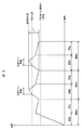
図2は、本実施形態のヒートパイプ式冷却装置の温度の経時変化を概略的に示すグラフである。縦軸に示す温度は、図1の温度検出部6で推算される作動媒体の温度である。横軸には、主回路素子の起動及び停止をひとまとまりとした運転(A、B、C)を時間の経過に沿って示している。
FIG. 2 is a graph schematically showing a change over time of the temperature of the heat pipe type cooling device of the present embodiment. The temperature shown on the vertical axis is the temperature of the working medium estimated by the
図2の場合、エレベータシステムの主回路素子が起動すると、主回路素子の温度が上昇し、熱伝達によりヒートパイプ2の温度も上昇する。しかし、最初の運転Aにおける起動では、当初、主回路素子の温度が低い状態にあるため、ヒートパイプ2の温度は、上記の作動媒体の温度の下限値以上の所定温度に達しない。このため、冷却ファン5は駆動しない。この後、主回路素子が停止することにより、ヒートパイプ2の温度は自然冷却により下降する。
In the case of FIG. 2, when the main circuit element of the elevator system is activated, the temperature of the main circuit element rises, and the temperature of the
次の運転Bにおいては、主回路素子の起動によりヒートパイプ2の温度が上昇し、上記の作動媒体の温度の下限値以上の所定温度に達すると、温度検出部6がONとなり、これに応じて冷却ファン5が駆動し、放熱部4における強制対流による冷却が行われる。冷却ファン5が駆動した後も、内封する蒸発した作動媒体の凝縮のため、ヒートパイプ2の温度はある程度上昇を続けるが、強制対流による冷却が継続されることで、所定時間経過後にヒートパイプ2の温度は下降へと転じ、所定温度まで下降する。ヒートパイプ2の温度が所定温度を下回ると、温度検出部6はOFFとなり、冷却ファン5は停止する。冷却ファン5が停止した後も、ヒートパイプ2の温度はある程度、下降を続ける。この後、運転Bにおける主回路素子の停止により、ヒートパイプ2の温度は自然冷却により更に下降する。
In the next operation B, when the temperature of the
次の運転Cにおいても、上述の運転Bと同様の制御が行われる。このような制御を繰り返すことにより、ヒートパイプ2の温度は上記の作動媒体の温度の下限値以上の所定の温度範囲に保たれ、主回路素子1の温度もヒートパイプ2の温度に応じたものとなる。
Also in the next operation C, the same control as the above-described operation B is performed. By repeating such control, the temperature of the
本実施形態によれば、上記の作動媒体の温度の下限値以上の所定温度を上回ったときに冷却ファン5を駆動することにより、ヒートパイプ2の温度を上記の作動媒体の温度の下限値以上の所定の温度範囲に保ち、被除熱対象物である主回路素子1の温度もそれに応じたものとし、これによって、1運転当たりの主回路素子1の温度変化の幅を小さくし、主回路素子1の寿命サイクルを有効に活用して長寿命化を図ることができる。
According to the present embodiment, the temperature of the
また、ヒートパイプ2の温度は作動液蒸発付近に保たれることから、冷却性能を高い状態に維持し、冷却効率の向上を図ることができる。
Moreover, since the temperature of the
さらに、冷却ファン5の駆動時間を従来に比べて短くすることができるため、省エネ化およびファン交換周期の延長を図ることができる。
Furthermore, since the driving time of the cooling
なお、前述した実施形態は、本発明を分かりやすく説明するために詳細に記載したものであり、必ずしも説明した全ての構成を備えるものに限定されるものではない。また、前述した実施形態の構成の一部について、他の構成の追加・削除・置き換えをすることは可能である。例えば、温度検出部6は、電源7と冷却ファン5との間に直列に配置され、熱伝導部材3に取り付けられるサーマルスイッチを例示したが、本発明はこれに限られるものではない。
The above-described embodiments are described in detail for easy understanding of the present invention, and are not necessarily limited to those having all the configurations described. Further, it is possible to add, delete, and replace other configurations for a part of the configuration of the above-described embodiment. For example, the
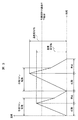
図3は、上述の実施形態との比較のため、従来のヒートパイプ式冷却装置における温度の経時変化を示したものである。 FIG. 3 shows a change in temperature over time in a conventional heat pipe type cooling device for comparison with the above-described embodiment.
本図に示すように、主回路の起動とともにヒートパイプ式冷却装置の冷却ファンを駆動する。冷却ファンの駆動は、主回路の停止後も一定時間行うように制御している。この場合に、例えば、エレベータが低温環境にあると、主回路素子の起動および停止からなる1運転当たりの温度変化の幅が比較的大きくなる。このような温度変化が生じると、主回路素子の劣化が進み、寿命が短くなるおそれがある。 As shown in the figure, the cooling fan of the heat pipe type cooling device is driven with the start of the main circuit. The cooling fan is controlled to be driven for a predetermined time after the main circuit is stopped. In this case, for example, when the elevator is in a low temperature environment, the width of the temperature change per operation including starting and stopping of the main circuit element is relatively large. When such a temperature change occurs, the main circuit element deteriorates and the life may be shortened.
また、ヒートパイプは、作動媒体の温度が低下し過ぎると、冷却性能が低下する。 Moreover, if the temperature of a working medium falls too much, a heat pipe will fall cooling performance.
本図に示す従来例においては、冷却ファンが駆動することにより、作動媒体が効率的に作動する温度範囲を大きく下回ることになる。このような状態のヒートパイプを用いて次に主回路の運転をする際には、ヒートパイプの立ち上げ時間が長くなる。このため、しばらくの間、冷却性能が低下した状態が続き、全体として冷却効率が低下する。 In the conventional example shown in this figure, when the cooling fan is driven, it is greatly below the temperature range in which the working medium operates efficiently. The next time the main circuit is operated using the heat pipe in such a state, the start-up time of the heat pipe becomes long. For this reason, the state in which the cooling performance is lowered continues for a while, and the cooling efficiency is lowered as a whole.
以下、エレベータシステムの構成の概略について図面を用いて説明する。 Hereinafter, an outline of the configuration of the elevator system will be described with reference to the drawings.
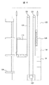
図4は、エレベータシステムの全体構成の例を示したものである。 FIG. 4 shows an example of the overall configuration of the elevator system.
本図において、乗りかご110が昇降する昇降路122内の上部には、複数のシーブ123が取り付けられており、このシーブ123には主ロープ125が巻装されている。主ロープ125の一端側にはカウンタウェイト124が取り付けられている。乗りかご110にはシーブが設けられており、このシーブに主ロープ125が巻装される。カウンタウェイト124は、乗りかご110の昇降時の動力を軽減する。
In this figure, a plurality of
本図においては、昇降路122の底面には、主ロープ125を駆動する駆動モータ127が配置されている。図示を省略しているが、乗り場側の各階128には、乗り場側開閉扉が設けられており、乗りかご110の前面に配置した乗りかご側開閉扉(乗りかごドア)と同期して開閉するようになっている。乗りかご110を含むエレベータ全体を制御するためのエレベータ制御装置101は、昇降路122内の壁面に設けられている。エレベータ制御装置101を構成する主回路素子(図示していない)には、除熱用のヒートパイプ式冷却装置130が付設されている。ここで、主回路素子は、駆動モータ127を運転するための電力を供給するインバータ等である。
In the drawing, a
なお、本図においては、駆動モータ127を昇降路122の底面に配置し、エレベータ制御装置101を下の階の高さに設置したが、本発明は、これに限定されるものではなく、駆動モータ127及びエレベータ制御装置101を最上階の機械室に配置してもよい。言い換えると、エレベータ制御装置101は、どこに配置しても、本発明のヒートパイプ式冷却装置を適用することが可能である。
In this figure, the
以上の説明においては、エレベータ制御装置の主回路素子の冷却にヒートパイプを用いる例を示したが、本発明は、これに限定されるものではなく、ガラス、セラミックスその他の大きな温度変化に弱い材料で形成された種々の被除熱対象物の冷却に適用することができる。 In the above description, an example in which a heat pipe is used for cooling the main circuit element of the elevator control device has been shown. However, the present invention is not limited to this, and glass, ceramics, and other materials that are vulnerable to large temperature changes. It can be applied to the cooling of various heat removal objects formed in (1).
1:被除熱対象物、2:ヒートパイプ、3:熱伝導部材、4:放熱部、5:冷却ファン、6:温度検出部、7:電源、101:エレベータ制御装置、110:乗りかご、122:昇降路、123:シーブ、124:カウンタウェイト、125:主ロープ、127:駆動モータ、128:階。 1: Heat removal target, 2: Heat pipe, 3: Heat conduction member, 4: Heat dissipation part, 5: Cooling fan, 6: Temperature detection part, 7: Power supply, 101: Elevator control device, 110: Ride car, 122: hoistway, 123: sheave, 124: counterweight, 125: main rope, 127: drive motor, 128: floor.
Claims (10)
前記放熱部を強制対流により冷却する冷却ファンと、を備え、
前記吸熱部における前記作動媒体の温度の検出又は推定が可能な温度検出部を有し、
前記温度検出部における検出又は推定により得られた温度が、前記被除熱対象物の温度変化の幅を小さくするために設定された前記作動媒体の温度の下限値以上の所定温度以上であるときは、前記冷却ファンを駆動する、ヒートパイプ式冷却装置。 A heat pipe that encloses the working medium, evaporates the working medium in a liquid state by heat from the object to be removed, and a heat pipe that has a heat radiating part that condenses the working medium in a gas state;
A cooling fan for cooling the heat radiating part by forced convection,
A temperature detection unit capable of detecting or estimating the temperature of the working medium in the heat absorption unit;
When the temperature obtained by detection or estimation in the temperature detection unit is equal to or higher than a predetermined temperature equal to or higher than a lower limit value of the temperature of the working medium set in order to reduce the temperature change range of the heat removal target. Is a heat pipe type cooling device for driving the cooling fan.
前記エレベータ制御装置は、被除熱対象物である主回路素子を有し、
前記被除熱対象物には、
作動媒体を内封し、前記被除熱対象物からの熱により液体状態の前記作動媒体を蒸発させる吸熱部、及び、気体状態の前記作動媒体を凝縮させる放熱部を有するヒートパイプと、
前記放熱部を強制対流により冷却する冷却ファンと、を含むヒートパイプ式冷却装置が付設してあり、
前記ヒートパイプ式冷却装置は、
前記吸熱部における前記作動媒体の温度の検出又は推定が可能な温度検出部を有し、
前記温度検出部における検出又は推定により得られた温度が、前記被除熱対象物の温度変化の幅を小さくするために設定された前記作動媒体の温度の下限値以上の所定温度以上であるときは、前記冷却ファンを駆動する、エレベータシステム。 An elevator system comprising a car, a drive motor, and an elevator controller,
The elevator control device has a main circuit element that is a heat removal target,
In the heat removal object,
A heat pipe that encloses the working medium, heat-absorbing part that evaporates the working medium in a liquid state by heat from the heat removal target, and a heat pipe that condenses the working medium in a gaseous state;
A heat pipe cooling device including a cooling fan that cools the heat dissipating part by forced convection,
The heat pipe type cooling device is:
A temperature detection unit capable of detecting or estimating the temperature of the working medium in the heat absorption unit;
When the temperature obtained by detection or estimation in the temperature detection unit is equal to or higher than a predetermined temperature equal to or higher than a lower limit value of the temperature of the working medium set in order to reduce the temperature change range of the heat removal target. Is an elevator system that drives the cooling fan.
Priority Applications (1)
| Application Number | Priority Date | Filing Date | Title |
|---|---|---|---|
| JP2015018147A JP6315704B2 (en) | 2015-02-02 | 2015-02-02 | Heat pipe type cooling device and elevator system equipped with the same |
Applications Claiming Priority (1)
| Application Number | Priority Date | Filing Date | Title |
|---|---|---|---|
| JP2015018147A JP6315704B2 (en) | 2015-02-02 | 2015-02-02 | Heat pipe type cooling device and elevator system equipped with the same |
Publications (2)
| Publication Number | Publication Date |
|---|---|
| JP2016143753A true JP2016143753A (en) | 2016-08-08 |
| JP6315704B2 JP6315704B2 (en) | 2018-04-25 |
Family
ID=56570804
Family Applications (1)
| Application Number | Title | Priority Date | Filing Date |
|---|---|---|---|
| JP2015018147A Active JP6315704B2 (en) | 2015-02-02 | 2015-02-02 | Heat pipe type cooling device and elevator system equipped with the same |
Country Status (1)
| Country | Link |
|---|---|
| JP (1) | JP6315704B2 (en) |
Cited By (3)
| Publication number | Priority date | Publication date | Assignee | Title |
|---|---|---|---|---|
| CN106211722A (en) * | 2016-08-31 | 2016-12-07 | 山东城市建设职业学院 | Elevator controlling machine room high-efficient ventilation cooling system |
| CN111899532A (en) * | 2020-07-17 | 2020-11-06 | 安徽信联建设工程有限公司 | Traffic signal controller for controlling multiple ports |
| WO2023021772A1 (en) * | 2021-08-18 | 2023-02-23 | 株式会社フジクラ | Temperature measuring device |
Citations (2)
| Publication number | Priority date | Publication date | Assignee | Title |
|---|---|---|---|---|
| JP2014055702A (en) * | 2012-09-12 | 2014-03-27 | Hitachi Ltd | Power conversion device and railway vehicle mounted with the same |
| JP2014123591A (en) * | 2012-12-20 | 2014-07-03 | Hitachi Ltd | Control unit and method of cooling the same |
-
2015
- 2015-02-02 JP JP2015018147A patent/JP6315704B2/en active Active
Patent Citations (2)
| Publication number | Priority date | Publication date | Assignee | Title |
|---|---|---|---|---|
| JP2014055702A (en) * | 2012-09-12 | 2014-03-27 | Hitachi Ltd | Power conversion device and railway vehicle mounted with the same |
| JP2014123591A (en) * | 2012-12-20 | 2014-07-03 | Hitachi Ltd | Control unit and method of cooling the same |
Cited By (6)
| Publication number | Priority date | Publication date | Assignee | Title |
|---|---|---|---|---|
| CN106211722A (en) * | 2016-08-31 | 2016-12-07 | 山东城市建设职业学院 | Elevator controlling machine room high-efficient ventilation cooling system |
| CN111899532A (en) * | 2020-07-17 | 2020-11-06 | 安徽信联建设工程有限公司 | Traffic signal controller for controlling multiple ports |
| CN111899532B (en) * | 2020-07-17 | 2023-10-13 | 安徽信联建设集团有限公司 | Traffic signal controller for controlling multiple intersections |
| WO2023021772A1 (en) * | 2021-08-18 | 2023-02-23 | 株式会社フジクラ | Temperature measuring device |
| JPWO2023021772A1 (en) * | 2021-08-18 | 2023-02-23 | ||
| JP7637248B2 (en) | 2021-08-18 | 2025-02-27 | 株式会社フジクラ | Temperature Measuring Device |
Also Published As
| Publication number | Publication date |
|---|---|
| JP6315704B2 (en) | 2018-04-25 |
Similar Documents
| Publication | Publication Date | Title |
|---|---|---|
| CN107846812B (en) | Double-fan type heat dissipation device and heat dissipation method of charging pile and charging pile | |
| US8922074B2 (en) | Elevator machine motor and drive and cooling thereof | |
| CN104133502B (en) | Cool down the method and system of electro-heat equipment | |
| CN107846813B (en) | Heat dissipation device and heat dissipation method of charging pile and charging pile | |
| JP6315704B2 (en) | Heat pipe type cooling device and elevator system equipped with the same | |
| CN110412541B (en) | Liquid cooling device for laser radar, laser radar system and vehicle | |
| CN209420222U (en) | cooling system | |
| JP2015517166A (en) | Oil cooling system for server and driving method thereof | |
| CN107839495B (en) | A charging pile and heat dissipation control method | |
| CN1182757C (en) | High-frequency heating apparatus and cooling system for magnetron drive power supply in the same | |
| JP6687663B2 (en) | Laser device including heat transfer device for radiating heat inside housing to outside | |
| CN106553947A (en) | The fall protection equipment of elevator | |
| CN106629302A (en) | Anti-falling speed reducing device of elevator | |
| JP2014090067A (en) | Cooling device of pole transformer | |
| CN112954988B (en) | Regulator cubicle convenient to heat dissipation | |
| CN111654997A (en) | Air-cooled type heat dissipation system and method for vehicle traveling | |
| JP2004345606A (en) | Vehicle cooling system | |
| CN117212749B (en) | A 380V maintenance-free explosion-proof lighting lamp | |
| CN110167319A (en) | Radiator, air conditioner and its control method for air conditioner | |
| CN106629314A (en) | Elevator protection device | |
| CN106629305A (en) | Anti-falling mechanism of lifting elevator | |
| JP2015194985A (en) | Structure box of electronic system having cooling device | |
| JP2014055702A (en) | Power conversion device and railway vehicle mounted with the same | |
| JP2007230464A (en) | Cargo vehicle | |
| JP2010199120A (en) | Cooling system of power conversion device |
Legal Events
| Date | Code | Title | Description |
|---|---|---|---|
| A621 | Written request for application examination |
Free format text: JAPANESE INTERMEDIATE CODE: A621 Effective date: 20170420 |
|
| A977 | Report on retrieval |
Free format text: JAPANESE INTERMEDIATE CODE: A971007 Effective date: 20180122 |
|
| A131 | Notification of reasons for refusal |
Free format text: JAPANESE INTERMEDIATE CODE: A131 Effective date: 20180206 |
|
| A521 | Request for written amendment filed |
Free format text: JAPANESE INTERMEDIATE CODE: A523 Effective date: 20180302 |
|
| TRDD | Decision of grant or rejection written | ||
| A01 | Written decision to grant a patent or to grant a registration (utility model) |
Free format text: JAPANESE INTERMEDIATE CODE: A01 Effective date: 20180320 |
|
| A61 | First payment of annual fees (during grant procedure) |
Free format text: JAPANESE INTERMEDIATE CODE: A61 Effective date: 20180323 |
|
| R150 | Certificate of patent or registration of utility model |
Ref document number: 6315704 Country of ref document: JP Free format text: JAPANESE INTERMEDIATE CODE: R150 |