JP2016141990A - Solar battery panel mounting member and solar battery panel mounting method - Google Patents
Solar battery panel mounting member and solar battery panel mounting method Download PDFInfo
- Publication number
- JP2016141990A JP2016141990A JP2015017152A JP2015017152A JP2016141990A JP 2016141990 A JP2016141990 A JP 2016141990A JP 2015017152 A JP2015017152 A JP 2015017152A JP 2015017152 A JP2015017152 A JP 2015017152A JP 2016141990 A JP2016141990 A JP 2016141990A
- Authority
- JP
- Japan
- Prior art keywords
- solar cell
- cell panel
- rail
- fixing
- support member
- Prior art date
- Legal status (The legal status is an assumption and is not a legal conclusion. Google has not performed a legal analysis and makes no representation as to the accuracy of the status listed.)
- Pending
Links
Images


Classifications
-
- Y—GENERAL TAGGING OF NEW TECHNOLOGICAL DEVELOPMENTS; GENERAL TAGGING OF CROSS-SECTIONAL TECHNOLOGIES SPANNING OVER SEVERAL SECTIONS OF THE IPC; TECHNICAL SUBJECTS COVERED BY FORMER USPC CROSS-REFERENCE ART COLLECTIONS [XRACs] AND DIGESTS
- Y02—TECHNOLOGIES OR APPLICATIONS FOR MITIGATION OR ADAPTATION AGAINST CLIMATE CHANGE
- Y02B—CLIMATE CHANGE MITIGATION TECHNOLOGIES RELATED TO BUILDINGS, e.g. HOUSING, HOUSE APPLIANCES OR RELATED END-USER APPLICATIONS
- Y02B10/00—Integration of renewable energy sources in buildings
- Y02B10/10—Photovoltaic [PV]
-
- Y—GENERAL TAGGING OF NEW TECHNOLOGICAL DEVELOPMENTS; GENERAL TAGGING OF CROSS-SECTIONAL TECHNOLOGIES SPANNING OVER SEVERAL SECTIONS OF THE IPC; TECHNICAL SUBJECTS COVERED BY FORMER USPC CROSS-REFERENCE ART COLLECTIONS [XRACs] AND DIGESTS
- Y02—TECHNOLOGIES OR APPLICATIONS FOR MITIGATION OR ADAPTATION AGAINST CLIMATE CHANGE
- Y02E—REDUCTION OF GREENHOUSE GAS [GHG] EMISSIONS, RELATED TO ENERGY GENERATION, TRANSMISSION OR DISTRIBUTION
- Y02E10/00—Energy generation through renewable energy sources
- Y02E10/50—Photovoltaic [PV] energy
Abstract
Description
本発明は、太陽電池パネル取付部材および太陽電池パネル取付方法に関する。 The present invention relates to a solar cell panel mounting member and a solar cell panel mounting method.
住宅の屋根や壁面に太陽電池パネルを取り付けて発電する住宅用の太陽光発電システムが知られている。太陽電池パネルは、粘土瓦、スレートなど、様々な屋根材に取り付けることができる。 2. Description of the Related Art Residential solar power generation systems that generate electricity by attaching solar panels to the roof or wall of a house are known. Solar cell panels can be attached to various roofing materials such as clay tiles and slate.
特許文献1には、折板屋根取り付け用太陽電池パネルアレイおよびその取り付け構造が開示されている。特許文献1の取り付け構造は、太陽電池パネルの横方向縁部を押さえる押し縁を、タイトフレームに加締められたボルトに挿通し、ナットで締め付けることによって固定している。これにより、太陽電池パネルを重ね式折板屋根に取り付けている。 Patent Document 1 discloses a folded solar panel array for roof mounting and a mounting structure thereof. The mounting structure of Patent Document 1 is fixed by inserting a pushing edge that holds the lateral edge of the solar cell panel through a bolt crimped to a tight frame and tightening with a nut. Thereby, the solar cell panel is attached to the stacked folding plate roof.
しかしながら、特許文献1の構造では、太陽電池パネルを固定するための押し縁を、タイトフレームに加締められたボルトを用いて固定しているため、押し縁の取付位置は折板屋根の頂部においてボルトが突出しいている位置に限定されてしまう。そのため、太陽電池パネルのサイズによっては適切に固定することができない場合がある。 However, in the structure of Patent Document 1, since the pressing edge for fixing the solar cell panel is fixed using a bolt crimped to the tight frame, the mounting position of the pressing edge is at the top of the folded plate roof. It will be limited to the position where the bolt is protruding. Therefore, depending on the size of the solar cell panel, it may not be properly fixed.
そこで、本発明は、上記の課題に鑑みなされたものであって、その目的は、様々な大きさの太陽電池パネルを折板屋根に取り付けることができる太陽電池パネル取付部材および太陽電池パネル取付方法を提供することにある。 Then, this invention was made | formed in view of said subject, The objective is the solar cell panel attachment member and solar cell panel attachment method which can attach the solar cell panel of various magnitude | sizes to a folded-plate roof. Is to provide.
上記の課題を解決するために、本発明の態様1に係る太陽電池パネル取付部材は、折板屋根に太陽電池パネルを取り付けるための太陽電池パネル取付部材であって、上記折板屋根の頂部の形状に対応する凹形状を有しており、上記折板屋根に固定される支持部材と、上記支持部材に固定されたレール部材と、上記レール部材に固定されるとともに上記太陽電池パネルの端部を把持するキャッチ部材と、を備えており、上記キャッチ部材は、上記レールに沿った任意の位置において上記レール部材に固定可能であることを特徴とする。 In order to solve the above-mentioned problem, a solar cell panel mounting member according to aspect 1 of the present invention is a solar cell panel mounting member for mounting a solar cell panel on a folded plate roof, and is a top of the folded plate roof. A support member fixed to the folded plate roof, a rail member fixed to the support member, and an end portion of the solar cell panel fixed to the rail member. And a catch member that grips the catch member, wherein the catch member can be fixed to the rail member at an arbitrary position along the rail.
上記の構成によれば、キャッチ部材は、太陽電池パネルの大きさに応じて、レールに沿った任意の位置においてレール部材に固定可能である。そのため、上記太陽電池パネル取付部材を用いることによって、様々な大きさの太陽電池パネルを折板屋根に取り付けることができる。 According to said structure, a catch member can be fixed to a rail member in the arbitrary positions along a rail according to the magnitude | size of a solar cell panel. Therefore, by using the solar cell panel mounting member, various sizes of solar cell panels can be mounted on the folded roof.
本発明の態様2に係る太陽電池パネル取付部材は、上記態様1において、上記レール部材を上記支持部材に固定するためのレール固定部材を備えており、上記レール部材の側面には孔部が設けられており、上記レール固定部材は、締結部品を用いて上記支持部材に固定されるとともに、上記孔部に引っ掛けて上記レール部材を固定するための第1掛止部を備えている構成であってもよい。
A solar cell panel mounting member according to
上記の構成によれば、レール固定部材の第1掛止部をレール部材の側面の孔部に引っ掛けることによって、長手方向に沿ったレール部材の移動を防止することができる。これにより、折板屋根が傾斜している場合であっても、太陽電池パネルの荷重によりレール部材が支持部材から外れることを防止することができる。 According to said structure, the movement of a rail member along a longitudinal direction can be prevented by hooking the 1st latching | locking part of a rail fixing member in the hole of the side surface of a rail member. Thereby, even if it is a case where a folded-plate roof inclines, it can prevent that a rail member remove | deviates from a support member by the load of a solar cell panel.
本発明の態様3に係る太陽電池パネル取付部材は、上記態様2において、上記キャッチ部材は、上記孔部に引っ掛けて固定するための第2掛止部を備えている構成であってもよい。
The solar cell panel mounting member according to
上記の構成によれば、キャッチ部材の第2掛止部をレール部材の側面の孔部に引っ掛けることによって、レール部材の長手方向に沿ったキャッチ部材の移動を防止することができる。これにより、折板屋根が傾斜している場合であっても、太陽電池パネルの荷重によりキャッチ部材が所望の固定位置からずれてしまうことを防止することができる。 According to said structure, the movement of the catch member along the longitudinal direction of a rail member can be prevented by hooking the 2nd latching | locking part of a catch member in the hole of the side surface of a rail member. Thereby, even if it is a case where a folded-plate roof inclines, it can prevent that a catch member shifts | deviates from a desired fixed position by the load of a solar cell panel.
本発明の態様4に係る太陽電池パネル取付部材は、上記態様1〜3の何れかにおいて、上記折板屋根は、互いに隣り合う折板の頂部を、貫通ボルトにより固定する重ね式折板屋根であり、上記支持部材は、上記貫通ボルトを用いて上記重ね式折板屋根に固定される構成であってもよい。
The solar cell panel mounting member according to
上記の構成によれば、通常の重ね式折板屋根に用いる貫通ボルトを用いて支持部材を重ね式折板屋根に固定することができる。そのため、上記の太陽電池パネル取付部材を用いることによって、部品点数を過度に増加させることなく、施工性を高めて、太陽電池パネルを折板屋根に取り付けることができる。 According to said structure, a supporting member can be fixed to a laminated folding board roof using the penetration bolt used for a normal laminated folding board roof. Therefore, by using the above-described solar cell panel mounting member, it is possible to enhance the workability without excessively increasing the number of parts and to attach the solar cell panel to the folded plate roof.
本発明の態様5に係る太陽電池パネル取付部材は、上記態様1〜4の何れかにおいて、上記キャッチ部材は、上記太陽電池パネルの端部を把持する第1把持部と、他の上記太陽電池パネルの端部を把持する第2把持部とを備えている構成であってもよい。
The solar cell panel mounting member according to
上記の構成によれば、2枚の太陽電池パネルを並べて折板屋根に固定する場合、1つのキャッチ部材により、上記2枚の太陽電池パネルの端部を把持することができる。これにより、部品点数を削減することができる。 According to said structure, when arrange | positioning two solar cell panels side by side and fixing to a folded-plate roof, the edge part of said two solar cell panels can be hold | gripped with one catch member. Thereby, the number of parts can be reduced.
本発明の態様6に係る太陽電池パネル取付部材は、上記態様2において、上記レール固定部材には、上記支持部材に固定する際に用いる上記締結部品が挿通する開口部が設けられており、上記開口部は縦長形状であり、上記レール固定部材を用いて上記レール部材を上記支持部材に固定したとき、上記開口部の長手方向は、上記支持部材における上記レール部材との対向面に対して傾斜している構成であってもよい。
In the solar cell panel mounting member according to
上記の構成によれば、レール固定部材を用いて支持部材とレール部材とを連結した場合、折板屋根が傾斜している場合であっても、開口部における締結部品の位置ずれを防止することができ、これにより、支持部材に対するレール部材の相対的な位置ずれを防止することができる。 According to said structure, when a support member and a rail member are connected using a rail fixing member, even if it is a case where a folded-plate roof inclines, it prevents position shift of the fastening components in an opening part. Thus, the relative displacement of the rail member with respect to the support member can be prevented.
さらに、上記の構成によれば、締結部品を用いてレール固定部材を支持部材に固定する際、支持部材に対するレール部材の相対位置を、開口部に沿って調整することができる。ここで、開口部は、上記対向面に対して傾斜した縦長形状であるため、レール固定部材の固定位置を高さ方向に調整することができる。これにより、太陽電池パネルの設置角度を調整することができ、高効率の太陽光発電を実現することができる。 Furthermore, according to said structure, when fixing a rail fixing member to a supporting member using a fastening component, the relative position of the rail member with respect to a supporting member can be adjusted along an opening part. Here, since the opening has a vertically long shape inclined with respect to the facing surface, the fixing position of the rail fixing member can be adjusted in the height direction. Thereby, the installation angle of a solar cell panel can be adjusted, and highly efficient solar power generation can be implement | achieved.
また、上記の課題を解決するために、本発明の態様7に係る太陽電池パネル取付方法は、折板屋根に太陽電池パネルを取り付けるための太陽電池パネル取付方法であって、上記折板屋根の頂部に、上記頂部の形状に対応する凹形状を有する支持部材を固定する支持部材固定工程と、レールを備えているレール部材を上記支持部材に固定するレール部材固定工程と、上記レールに沿って、上記太陽電池パネルの大きさに応じた位置に、上記太陽電池パネルの端部を把持するキャッチ部材を固定するキャッチ部材固定工程と、を含んでいることを特徴とする。 Moreover, in order to solve said subject, the solar cell panel attachment method which concerns on aspect 7 of this invention is a solar cell panel attachment method for attaching a solar cell panel to a folded-plate roof, Comprising: A support member fixing step of fixing a support member having a concave shape corresponding to the shape of the top portion to the top portion, a rail member fixing step of fixing a rail member having a rail to the support member, and along the rail And a catch member fixing step of fixing a catch member for holding an end of the solar cell panel at a position corresponding to the size of the solar cell panel.
本発明によれば、様々な大きさの太陽電池パネルを折板屋根に取り付けることができる。 According to the present invention, various sizes of solar cell panels can be attached to the folded roof.
〔実施形態1〕
以下、本発明の実施の形態について、図1〜10に基づいて詳細に説明する。
Embodiment 1
Hereinafter, embodiments of the present invention will be described in detail with reference to FIGS.
<太陽電池パネル取付部材>
図1は、本実施形態の太陽電池パネル取付部材を用いて折板屋根に太陽電池パネルを取り付けた状態を示す斜視図である。
<Solar cell panel mounting member>
FIG. 1 is a perspective view showing a state in which a solar cell panel is attached to a folded plate roof using the solar cell panel attachment member of the present embodiment.
本実施形態の太陽電池パネル取付部材1は、折板屋根に太陽電池パネル3を取り付けるための部材であり、特に、重ね式折板屋根2に太陽電池パネル3を取り付ける部材として好適に用いることができる。
The solar cell panel attachment member 1 of this embodiment is a member for attaching the
太陽電池パネル取付部材1は、折板屋根に固定される支持部材10と、支持部材10の上面に載置されて固定されるレール部材20と、レール部材20に固定されるとともに太陽電池パネル3の端部を把持するキャッチ部材30と、レール部材20を支持部材10に固定するためのレール固定部材40と、を備えている。
The solar cell panel mounting member 1 is fixed to the folded plate roof, the
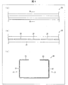
(重ね式折板屋根)
図2は重ね式折板屋根の要部の構成を示す図であり、(a)は折板の斜視図であり、(b)は折板同士の接合部を示す側面図である。
(Stacked folded roof)
2A and 2B are diagrams showing a configuration of a main part of the stacked folding plate roof, wherein FIG. 2A is a perspective view of the folded plate, and FIG. 2B is a side view showing a joint portion between the folded plates.
図2に示すように、重ね式折板屋根は、図示しない鉄骨下地(梁)の上に所定の間隔で配置されたタイトフレーム4に、端部を重ねるようにして折板5を葺くことによって形成された屋根である。折板5は、頂部と底部とを交互に有するように折り曲げられており、互いに隣り合う折板5は、頂部を貫通する貫通ボルト6を用いてタイトフレーム4に固定されている。
As shown in FIG. 2, the folded folding plate roof is obtained by rolling the folded
(支持部材10)
図3は本実施形態の太陽電池パネル取付部材の支持部材の構成を示す図であり、(a)は平面図であり、(b)は側面図であり、(c)は(a)のA−A線矢視断面図である。
(Supporting member 10)
FIG. 3 is a diagram showing the configuration of the support member of the solar cell panel mounting member of this embodiment, (a) is a plan view, (b) is a side view, and (c) is A in (a). FIG.
図3の(a)〜(c)に示すように、支持部材10は、概略的にはリップ溝型鋼(C形鋼)であり、その底面11は、折板屋根の頂部の形状に対応する凹形状を有している。底面11には、支持部材10を折板屋根2にボルト締めするための貫通穴12が設けられている。
As shown to (a)-(c) of FIG. 3, the supporting
支持部材10の側面13には、レール固定部材40をボルト締めして固定するための穴14が設けられている。レール固定部材40の固定位置の自由度を高めるために、穴14の数は多いことが好ましい。本実施形態の支持部材10の各側面13には、穴14が3つずつ設けられている。
The
(レール部材20)
図4は本実施形態の太陽電池パネル取付部材のレール部材の構成を示す図であり、(a)は平面図であり、(b)は側面図であり、(c)は(a)のB−B線矢視断面図である。
(Rail member 20)
FIG. 4 is a diagram showing the configuration of the rail member of the solar cell panel mounting member of the present embodiment, (a) is a plan view, (b) is a side view, and (c) is B in (a). FIG.
図4の(a)〜(c)に示すように、レール部材20は、リップ溝型鋼(C形鋼)である。レール部材20の側面21には、複数の孔部22が設けられている。孔部22は、レール部材20の長手方向に沿った横長の形状を有しており、レール部材20の長手方向に沿って複数の孔部22が配列されている。孔部22の大きさおよび孔部22の数は特に限定されず、適宜設計することができる。
As shown to (a)-(c) of FIG. 4, the
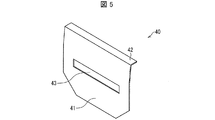
(レール固定部材40)
図5は本実施形態の太陽電池パネル取付部材のレール固定部材の構成を示す斜視図である。
(Rail fixing member 40)
FIG. 5 is a perspective view showing the configuration of the rail fixing member of the solar cell panel mounting member of the present embodiment.
図5に示すように、レール固定部材40は、平板状の本体部41と、本体部41から略90°曲げられた掛止部42(第1掛止部)とを備えている。本体部41には、長方形状(縦長形状)の開口部43が設けられている。
As shown in FIG. 5, the
(キャッチ部材30)
図6は本実施形態の太陽電池パネル取付部材のキャッチ部材の構成を示す斜視図である。
(Catch member 30)
FIG. 6 is a perspective view showing the configuration of the catch member of the solar cell panel mounting member of the present embodiment.
図6に示すように、キャッチ部材30は、太陽電池パネル3の端部を把持するZ形鋼の把持部31と、平板状の固定部32と、ボルト33とを備えている。
As shown in FIG. 6, the
把持部31の一つの面と、固定部32の略中央部には、ボルト33が挿通される穴が設けられており、ボルトとナットとを締めることにより把持部31と固定部32との間隔を調整可能である。
A hole through which the
図6では、六角形状の固定部32を用いたキャッチ部材30を例示しているが、固定部32の形状は特に限定されず、正方形状であってもよい。
In FIG. 6, the
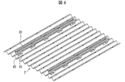
<太陽電池パネル取付工程>
以下、重ね式折板屋根に太陽電池パネルを取り付けるための太陽電池パネル取付工程(太陽電池パネル取付方法)について、図7〜10に基づいて説明する。
<Solar cell panel mounting process>
Hereinafter, the solar cell panel attachment process (solar cell panel attachment method) for attaching the solar cell panel to the stacked folding plate roof will be described with reference to FIGS.
図7は、折板屋根に支持部材を固定した状態を示す図である。 FIG. 7 is a diagram illustrating a state in which the support member is fixed to the folded plate roof.
図8は、支持部材にレール部材を固定した状態を示す斜視図である。 FIG. 8 is a perspective view showing a state in which the rail member is fixed to the support member.
図9は、支持部材とレール部材との連結部分の側面図である。 FIG. 9 is a side view of a connecting portion between the support member and the rail member.
図10は、レール部材にキャッチ部材を取り付けた状態を示す斜視図である。 FIG. 10 is a perspective view showing a state in which the catch member is attached to the rail member.
太陽電池パネル取付工程では、第一に、図7に示すように、支持部材10の底面11の凹形状を重ね式の折板屋根2の頂部に合わせるようにして、取り付けようとする太陽電池パネル3の大きさに応じて所定の数の支持部材10を所定の間隔で重ね式の折板屋根2に載置するとともに、ボルト締めにより固定する(支持部材固定工程)。
In the solar cell panel mounting step, first, as shown in FIG. 7, the solar cell panel to be mounted by matching the concave shape of the bottom surface 11 of the
このとき、折板5をタイトフレームに固定するための貫通ボルト6を、支持部材10の貫通穴12に挿通させて支持部材10を固定することが好ましい。
At this time, it is preferable to fix the
このように、折板5をタイトフレームに固定するための貫通ボルト6を用いて支持部材10を固定することにより、支持部材10を折板屋根2に固定するための特別な部材を必要とせず、部品点数を少なくすることができる。
Thus, by fixing the
次に、図8に示すように、レール固定部材40を用いて、レール部材20を支持部材10の上面に載置した状態で固定する(レール部材固定工程)。具体的には、図9に示すように、支持部材10の上面にレール部材20を載置した状態で、レール固定部材40の掛止部42をレール部材20の孔部22に掛止するとともに、レール固定部材40の開口部43を支持部材10の穴14を挿通するボルト(締結部品)を用いて締め付け固定する。
Next, as shown in FIG. 8, using the
次に、図10に示すように、レール部材20にキャッチ部材30を固定する(キャッチ部材固定工程)。具体的には、把持部31と固定部32とでレール部材20の端部23を挟み、レール部材20の長手方向に沿って所望の位置までキャッチ部材30をスライドさせた後、ボルト締めにより把持部31と固定部32とによりレール部材20の端部23を挟み込むことによって、レール部材20にキャッチ部材を固定する。
Next, as shown in FIG. 10, the
そして、図1に示すように、キャッチ部材30の把持部31で太陽電池パネル3の端部を把持するように太陽電池パネル3を配置する。そして、太陽電池パネル3の他端を他のキャッチ部材30により把持する。このように、太陽電池パネル3の両端部をキャッチ部材30で挟み込んで固定することによって、太陽電池パネル3を折板屋根2に取り付けることができる。
And as shown in FIG. 1, the
本実施形態の太陽電池パネル取付部材1を用いた太陽電池パネル取付工程によれば、レール部材20の長手方向に沿ってキャッチ部材30をスライドさせ、太陽電池パネルの大きさに応じた任意の位置においてキャッチ部材30をレール部材20に固定することができる。そのため、様々な大きさの太陽電池パネル3を折板屋根2に取り付けることができる。
According to the solar cell panel mounting step using the solar cell panel mounting member 1 of the present embodiment, the
〔実施形態2〕
本発明の他の実施形態について、図11に基づいて説明すれば、以下のとおりである。なお、説明の便宜上、前記実施形態にて説明した部材と同じ機能を有する部材については、同じ符号を付記し、その説明を省略する。
[Embodiment 2]
Another embodiment of the present invention is described below with reference to FIG. For convenience of explanation, members having the same functions as those described in the embodiment are given the same reference numerals, and descriptions thereof are omitted.
図11の(a)は、本実施形態の太陽電池パネル取付部材のキャッチ部材の構成を示す斜視図であり、図11の(b)は、本実施形態の太陽電池パネル取付部材のキャッチ部材により太陽電池パネルを把持した状態を示す側面図である。 FIG. 11A is a perspective view showing the configuration of the catch member of the solar cell panel mounting member of the present embodiment, and FIG. 11B is a view of the catch member of the solar cell panel mounting member of the present embodiment. It is a side view which shows the state which hold | gripped the solar cell panel.
図11の(a)・(b)に示すように、本実施形態の太陽電池パネル取付部材のキャッチ部材130は、太陽電池パネル3Aの端部を把持する第1把持部131と、他の太陽電池パネル3Bの端部を把持する第2把持部132とを備えている。
As shown in FIGS. 11A and 11B, the
本実施形態のキャッチ部材130を用いることによって、2枚の太陽電池パネル3A・3Bを並べて折板屋根に取り付ける場合、1つのキャッチ部材により、2枚の太陽電池パネル3A・3Bの端部を把持することができる。これにより、部品点数を削減することができる。
When the two
〔実施形態3〕
本発明の他の実施形態について、図12に基づいて説明すれば、以下のとおりである。なお、説明の便宜上、前記実施形態にて説明した部材と同じ機能を有する部材については、同じ符号を付記し、その説明を省略する。
[Embodiment 3]
Another embodiment of the present invention is described below with reference to FIG. For convenience of explanation, members having the same functions as those described in the embodiment are given the same reference numerals, and descriptions thereof are omitted.
図12の(a)は、本実施形態の太陽電池パネル取付部材のキャッチ部材の構成を示す斜視図であり、図12の(b)は、本実施形態の太陽電池パネル取付部材のキャッチ部材により太陽電池パネルを把持した状態を示す斜視図である。 (A) of FIG. 12 is a perspective view which shows the structure of the catch member of the solar cell panel attachment member of this embodiment, (b) of FIG. 12 is by the catch member of the solar cell panel attachment member of this embodiment. It is a perspective view which shows the state which hold | gripped the solar cell panel.
図12の(a)・(b)に示すように、本実施形態の太陽電池パネル取付部材のキャッチ部材230は、太陽電池パネル3の端部を把持する把持部31と、レール部材20の孔部22の端部に引っ掛けて固定するため掛止部232(第2掛止部)とを備えている。
As shown in FIGS. 12A and 12B, the
本実施形態のキャッチ部材230を用い、キャッチ部材230の掛止部232をレール部材20の側面の孔部22に引っ掛けることによって、レール部材20の長手方向に沿ったキャッチ部材230の移動を防止することができる。これにより、折板屋根2が傾斜している場合であっても、太陽電池パネル3の荷重によりキャッチ部材230が所望の固定位置からずれてしまうことを防止することができる。
By using the
〔実施形態4〕
本発明の他の実施形態について、図13に基づいて説明すれば、以下のとおりである。なお、説明の便宜上、前記実施形態にて説明した部材と同じ機能を有する部材については、同じ符号を付記し、その説明を省略する。
[Embodiment 4]
The following will describe another embodiment of the present invention with reference to FIG. For convenience of explanation, members having the same functions as those described in the embodiment are given the same reference numerals, and descriptions thereof are omitted.
図13の(a)および(b)は、本実施形態の太陽電池パネル取付部材のレール固定部材の構成を示す斜視図であり、図13の(c)は、支持部材とレール部材との連結部分の側面図である。 FIGS. 13A and 13B are perspective views showing the configuration of the rail fixing member of the solar cell panel mounting member of the present embodiment, and FIG. 13C shows the connection between the support member and the rail member. It is a side view of a part.
図13の(a)に示すように、レール固定部材140Aは、本体部41とのなす角度が略90°となるように曲げられた掛止部42と、掛止部42とのなす角度が略65°となるように曲げ返された先端部44と、を備えている。
As shown in FIG. 13A, the rail fixing member 140 </ b> A has an angle formed between the
また、図13の(b)に示すように、レール固定部材140Bは、本体部41とのなす角度が略90°となるように曲げられた掛止部42と、掛止部42とのなす角度が略65°となるように曲げ返された先端部44と、を備えている。
Further, as shown in FIG. 13B, the
上記の構成によれば、支持部材10とレール固定部材20とを挟むようにして、レール固定部材140Aとレール固定部材140Bとを互いに対向させ、それぞれの掛止部42および先端部44をレール部材20の孔部22に掛止することによって、レール部材20からレール固定部材140A・140Bが外れることを防止することができる。これにより、レール固定部材140A・140Bを用いて、レール部材20を支持部材10に確実に固定することができる。
According to the above configuration, the rail fixing member 140 </ b> A and the rail fixing member 140 </ b> B are opposed to each other so as to sandwich the
また、図13の(a)に示すように、本実施形態のレール固定部材140Aの開口部143Aの長手方向は、掛止部42(第1掛止部)の長手方向に対して傾斜している。
As shown in FIG. 13A, the longitudinal direction of the
また、図13の(c)に示すように、レール固定部材140を用いて支持部材10とレール部材20とを連結したとき、開口部143Aの長手方向は、支持部材10とレール部材20との接触面に対して傾斜している。なお、図13の(c)に示すように、図中右側が折板屋根2の頂部(棟)に近い上側であり、図中左側が折板屋根2の頂部(棟)から遠い下側である場合、レール固定部材140の開口部143Aは、図中右下から左上にかけて開口していることが好ましい。
Further, as shown in FIG. 13C, when the
図示を省略するが、同様に、図中右側が頂部(棟)に近い上側であり、図中左側が頂部(棟)から遠い下側である場合、レール固定部材140Bの開口部143Aは、図中右下から左上にかけて開口していることが好ましい。
Although illustration is omitted, similarly, when the right side in the figure is the upper side near the top (building) and the left side in the figure is the lower side far from the top (building), the
実施形態1のレール固定部材40を用いて支持部材10とレール部材20とを連結した場合であって、折板屋根2が傾斜している場合、支持部材10とレール部材20との接触面に平行な方向に、太陽電池パネル3の荷重に応じた力が加わることによって、開口部43におけるボルトの位置がずれ、支持部材10に対するレール部材20の相対的な位置がずれてしまう。
When the
これに対して、本実施形態のレール固定部材140A・140Bを用いて支持部材10とレール部材20とを連結した場合、開口部143A・143Bの長手方向が支持部材10におけるレール部材20との対向面に対して傾斜しているため、折板屋根2が傾斜している場合であっても、開口部143A・143Bにおけるボルトの位置ずれを防止することができ、これにより、支持部材10に対するレール部材20の相対的な位置ずれを防止することができる。
On the other hand, when the
さらに、本実施形態のレール固定部材140A・140Bおよびボルトを用いてレール固定部材20を支持部材10に固定する際、支持部材10に対するレール部材20の相対位置を、開口部143A・143Bに沿って調整することができる。ここで、開口部143A・143Bは、上記対向面に対して傾斜した縦長形状であるため、レール固定部材20の固定位置を高さ方向に調整することができる。これにより、太陽電池パネル3の設置角度を調整することができ、高効率の太陽光発電を実現することができる。
Furthermore, when the
本発明は上述した各実施形態に限定されるものではなく、請求項に示した範囲で種々の変更が可能であり、異なる実施形態にそれぞれ開示された技術的手段を適宜組み合わせて得られる実施形態についても本発明の技術的範囲に含まれる。 The present invention is not limited to the above-described embodiments, and various modifications are possible within the scope shown in the claims, and embodiments obtained by appropriately combining technical means disclosed in different embodiments. Is also included in the technical scope of the present invention.
本発明は、太陽電池パネルを取り付けた折板屋根の工法として好適に利用することができる。 INDUSTRIAL APPLICABILITY The present invention can be suitably used as a method for manufacturing a folded plate roof to which a solar cell panel is attached.
1 太陽電池パネル取付部材
2 折板屋根
3、3A、3B 太陽電池パネル
5 折板
6 貫通ボルト
10 支持部材
20 レール部材
22 孔部
30、130、230 キャッチ部材
31 把持部
40、140 レール固定部材
42 掛止部(第1掛止部)
131 第1把持部
132 第2把持部
232 掛止部(第2掛止部)
DESCRIPTION OF SYMBOLS 1 Solar cell
131
Claims (7)
上記折板屋根の頂部の形状に対応する凹形状を有しており、上記折板屋根に固定される支持部材と、
上記支持部材に固定されるレール部材と、
上記レール部材に固定されるとともに上記太陽電池パネルの端部を把持するキャッチ部材と、を備えており、
上記キャッチ部材は、上記レール部材の長手方向に沿った任意の位置において上記レール部材に固定可能であることを特徴とする太陽電池パネル取付部材。 A solar cell panel mounting member for mounting a solar cell panel on a folded plate roof,
A support member that has a concave shape corresponding to the shape of the top of the folded plate roof, and is fixed to the folded plate roof;
A rail member fixed to the support member;
A catch member fixed to the rail member and gripping an end of the solar cell panel,
The solar cell panel mounting member, wherein the catch member can be fixed to the rail member at an arbitrary position along the longitudinal direction of the rail member.
上記レール部材の側面には孔部が設けられており、
上記レール固定部材は、締結部品を用いて上記支持部材に固定されるとともに、上記孔部に引っ掛けて上記レール部材を固定するための第1掛止部を備えていることを特徴とする請求項1に記載の太陽電池パネル取付部材。 A rail fixing member for fixing the rail member to the support member;
A hole is provided on a side surface of the rail member,
The rail fixing member is fixed to the support member using a fastening part, and includes a first latching portion that is hooked into the hole to fix the rail member. The solar cell panel mounting member according to 1.
上記支持部材は、上記貫通ボルトを用いて上記重ね式折板屋根に固定されることを特徴とする請求項1〜3の何れか1項に記載の太陽電池パネル取付部材。 The folded plate roof is a stacked folded plate roof that fixes the tops of adjacent folded plates with through bolts,
The solar cell panel mounting member according to any one of claims 1 to 3, wherein the support member is fixed to the stacked folded plate roof using the through bolts.
上記開口部は縦長形状であり、
上記レール固定部材を用いて上記レール部材を上記支持部材に固定したとき、上記開口部の長手方向は、上記支持部材における上記レール部材との対向面に対して傾斜していることを特徴とする請求項2に記載の太陽電池パネル取付部材。 The rail fixing member is provided with an opening through which the fastening component used when fixing to the support member is inserted,
The opening has a vertically long shape,
When the rail member is fixed to the support member using the rail fixing member, the longitudinal direction of the opening is inclined with respect to the surface of the support member facing the rail member. The solar cell panel mounting member according to claim 2.
上記折板屋根の頂部に、上記頂部の形状に対応する凹形状を有する支持部材を固定する支持部材固定工程と、
レール部材を上記支持部材に固定するレール部材固定工程と、
上記レール部材に沿って、上記太陽電池パネルの大きさに応じた位置に、上記太陽電池パネルの端部を把持するキャッチ部材を固定するキャッチ部材固定工程と、を含んでいることを特徴とする太陽電池パネル取付方法。 A solar cell panel mounting method for mounting a solar cell panel on a folded plate roof,
A support member fixing step of fixing a support member having a concave shape corresponding to the shape of the top portion to the top portion of the folded plate roof;
A rail member fixing step of fixing the rail member to the support member;
A catch member fixing step of fixing a catch member for gripping an end of the solar cell panel at a position corresponding to the size of the solar cell panel along the rail member. Solar panel mounting method.
Priority Applications (1)
| Application Number | Priority Date | Filing Date | Title |
|---|---|---|---|
| JP2015017152A JP2016141990A (en) | 2015-01-30 | 2015-01-30 | Solar battery panel mounting member and solar battery panel mounting method |
Applications Claiming Priority (1)
| Application Number | Priority Date | Filing Date | Title |
|---|---|---|---|
| JP2015017152A JP2016141990A (en) | 2015-01-30 | 2015-01-30 | Solar battery panel mounting member and solar battery panel mounting method |
Publications (1)
| Publication Number | Publication Date |
|---|---|
| JP2016141990A true JP2016141990A (en) | 2016-08-08 |
Family
ID=56569875
Family Applications (1)
| Application Number | Title | Priority Date | Filing Date |
|---|---|---|---|
| JP2015017152A Pending JP2016141990A (en) | 2015-01-30 | 2015-01-30 | Solar battery panel mounting member and solar battery panel mounting method |
Country Status (1)
| Country | Link |
|---|---|
| JP (1) | JP2016141990A (en) |
Cited By (3)
| Publication number | Priority date | Publication date | Assignee | Title |
|---|---|---|---|---|
| JP2020117901A (en) * | 2019-01-22 | 2020-08-06 | Wwb株式会社 | Solar power panel frame, solar power device and installation method of solar power device |
| JP7061332B1 (en) | 2021-11-12 | 2022-04-28 | 株式会社Jts | Solar panel mounting structure |
| JP7061331B1 (en) | 2021-11-12 | 2022-04-28 | 株式会社Jts | Roof reinforcement structure and its reinforcement members |
Citations (5)
| Publication number | Priority date | Publication date | Assignee | Title |
|---|---|---|---|---|
| JP2012007295A (en) * | 2010-06-22 | 2012-01-12 | Otis co ltd | Rooftop fixture |
| JP2012180668A (en) * | 2011-03-01 | 2012-09-20 | Daidohant Co Ltd | Installation device of solar cell module |
| JP2014015794A (en) * | 2012-07-10 | 2014-01-30 | Okuchi Kensan Kk | Crosspiece for mount for planar article |
| JP3189187U (en) * | 2013-12-17 | 2014-02-27 | 株式会社屋根技術研究所 | Folded plate roof fixing member |
| JP2014136900A (en) * | 2013-01-17 | 2014-07-28 | Aikawa Press Kogyo:Kk | Mounting structure of solar panel |
-
2015
- 2015-01-30 JP JP2015017152A patent/JP2016141990A/en active Pending
Patent Citations (5)
| Publication number | Priority date | Publication date | Assignee | Title |
|---|---|---|---|---|
| JP2012007295A (en) * | 2010-06-22 | 2012-01-12 | Otis co ltd | Rooftop fixture |
| JP2012180668A (en) * | 2011-03-01 | 2012-09-20 | Daidohant Co Ltd | Installation device of solar cell module |
| JP2014015794A (en) * | 2012-07-10 | 2014-01-30 | Okuchi Kensan Kk | Crosspiece for mount for planar article |
| JP2014136900A (en) * | 2013-01-17 | 2014-07-28 | Aikawa Press Kogyo:Kk | Mounting structure of solar panel |
| JP3189187U (en) * | 2013-12-17 | 2014-02-27 | 株式会社屋根技術研究所 | Folded plate roof fixing member |
Cited By (6)
| Publication number | Priority date | Publication date | Assignee | Title |
|---|---|---|---|---|
| JP2020117901A (en) * | 2019-01-22 | 2020-08-06 | Wwb株式会社 | Solar power panel frame, solar power device and installation method of solar power device |
| JP7384557B2 (en) | 2019-01-22 | 2023-11-21 | Wwb株式会社 | Mount for solar power generation panel, solar power generation device, and installation method of solar power generation device |
| JP7061332B1 (en) | 2021-11-12 | 2022-04-28 | 株式会社Jts | Solar panel mounting structure |
| JP7061331B1 (en) | 2021-11-12 | 2022-04-28 | 株式会社Jts | Roof reinforcement structure and its reinforcement members |
| JP2023072512A (en) * | 2021-11-12 | 2023-05-24 | 株式会社Jts | Roof reinforcement structure, and roof reinforcing member |
| JP2023072629A (en) * | 2021-11-12 | 2023-05-24 | 株式会社Jts | Solar panel attachment structure |
Similar Documents
| Publication | Publication Date | Title |
|---|---|---|
| US8511008B2 (en) | Solar cell module attachment structure and solar cell apparatus | |
| WO2011078382A1 (en) | Structure installation mount, support for structure installation, and solar power generation system | |
| JP5731203B2 (en) | Solar power unit mounting device | |
| JP4795649B2 (en) | Solar power plant | |
| US8656660B2 (en) | Rooftop module interlock system | |
| WO2011129321A1 (en) | Solar cell module support structure, method of constructing said support structure, and solar photovoltaic power generation system using said support structure | |
| JP5172039B2 (en) | Mounting method for mounting | |
| JP2016141990A (en) | Solar battery panel mounting member and solar battery panel mounting method | |
| JP6558632B2 (en) | Solar power plant | |
| WO2014010026A1 (en) | Mounting for solar cell panel | |
| JP2017043963A (en) | Member and method for mounting solar battery panel | |
| JP2014047570A (en) | Fixture for solar panels | |
| JP2016008418A (en) | Retainer and enclosure for building | |
| JP4659072B2 (en) | Solar cell installation structure and installation method | |
| JP2013007192A (en) | Fitting structure for solar battery and the like to be mounted on roof | |
| JP5944695B2 (en) | Building fixture | |
| JP5683360B2 (en) | Mounting structure for installation on the roof | |
| JP2015055042A (en) | Installation member for equipment and equipment installation roof | |
| JP2013119729A (en) | Solar battery panel laying structure and intermediate holding member for solar battery panel | |
| JP2021119288A (en) | Installation structure of functional panel | |
| JP5965376B2 (en) | Solar cell module support structure and solar power generation system using the support structure | |
| JP2015021239A (en) | Solar cell module fitting structure for seam type folded plate roof | |
| CN211949269U (en) | Clamping device and photovoltaic roof | |
| JP2018040229A (en) | Solar power generation device | |
| JP2014173360A (en) | Support structure for solar battery panel |
Legal Events
| Date | Code | Title | Description |
|---|---|---|---|
| A02 | Decision of refusal |
Free format text: JAPANESE INTERMEDIATE CODE: A02 Effective date: 20160809 |