JP2016138880A - 電流トランスによる試験装置用電力誘導システム - Google Patents
電流トランスによる試験装置用電力誘導システム Download PDFInfo
- Publication number
- JP2016138880A JP2016138880A JP2016004805A JP2016004805A JP2016138880A JP 2016138880 A JP2016138880 A JP 2016138880A JP 2016004805 A JP2016004805 A JP 2016004805A JP 2016004805 A JP2016004805 A JP 2016004805A JP 2016138880 A JP2016138880 A JP 2016138880A
- Authority
- JP
- Japan
- Prior art keywords
- current
- test apparatus
- electrical
- electrical conductor
- clamp
- Prior art date
- Legal status (The legal status is an assumption and is not a legal conclusion. Google has not performed a legal analysis and makes no representation as to the accuracy of the status listed.)
- Ceased
Links
- 238000012360 testing method Methods 0.000 title claims abstract description 184
- 230000006698 induction Effects 0.000 title 1
- 239000004020 conductor Substances 0.000 claims abstract description 71
- 230000001939 inductive effect Effects 0.000 abstract description 3
- 230000005540 biological transmission Effects 0.000 description 12
- 238000006243 chemical reaction Methods 0.000 description 6
- 239000003990 capacitor Substances 0.000 description 5
- 230000007613 environmental effect Effects 0.000 description 5
- 241000282414 Homo sapiens Species 0.000 description 4
- 238000005259 measurement Methods 0.000 description 4
- 230000001681 protective effect Effects 0.000 description 3
- 230000008901 benefit Effects 0.000 description 2
- 238000012423 maintenance Methods 0.000 description 2
- 230000007246 mechanism Effects 0.000 description 2
- 238000012544 monitoring process Methods 0.000 description 2
- 230000003287 optical effect Effects 0.000 description 2
- 230000004913 activation Effects 0.000 description 1
- 230000008878 coupling Effects 0.000 description 1
- 238000010168 coupling process Methods 0.000 description 1
- 238000005859 coupling reaction Methods 0.000 description 1
- 238000010586 diagram Methods 0.000 description 1
- 238000011156 evaluation Methods 0.000 description 1
- 238000009499 grossing Methods 0.000 description 1
- 238000009434 installation Methods 0.000 description 1
- 230000003993 interaction Effects 0.000 description 1
- 230000007774 longterm Effects 0.000 description 1
- 238000012986 modification Methods 0.000 description 1
- 230000004048 modification Effects 0.000 description 1
- 230000009467 reduction Effects 0.000 description 1
- 239000003381 stabilizer Substances 0.000 description 1
- 238000006467 substitution reaction Methods 0.000 description 1
Images


Classifications
-
- G—PHYSICS
- G01—MEASURING; TESTING
- G01R—MEASURING ELECTRIC VARIABLES; MEASURING MAGNETIC VARIABLES
- G01R31/00—Arrangements for testing electric properties; Arrangements for locating electric faults; Arrangements for electrical testing characterised by what is being tested not provided for elsewhere
-
- G—PHYSICS
- G01—MEASURING; TESTING
- G01R—MEASURING ELECTRIC VARIABLES; MEASURING MAGNETIC VARIABLES
- G01R15/00—Details of measuring arrangements of the types provided for in groups G01R17/00 - G01R29/00, G01R33/00 - G01R33/26 or G01R35/00
- G01R15/14—Adaptations providing voltage or current isolation, e.g. for high-voltage or high-current networks
-
- G—PHYSICS
- G01—MEASURING; TESTING
- G01R—MEASURING ELECTRIC VARIABLES; MEASURING MAGNETIC VARIABLES
- G01R1/00—Details of instruments or arrangements of the types included in groups G01R5/00 - G01R13/00 and G01R31/00
- G01R1/20—Modifications of basic electric elements for use in electric measuring instruments; Structural combinations of such elements with such instruments
- G01R1/22—Tong testers acting as secondary windings of current transformers
-
- G—PHYSICS
- G01—MEASURING; TESTING
- G01D—MEASURING NOT SPECIALLY ADAPTED FOR A SPECIFIC VARIABLE; ARRANGEMENTS FOR MEASURING TWO OR MORE VARIABLES NOT COVERED IN A SINGLE OTHER SUBCLASS; TARIFF METERING APPARATUS; MEASURING OR TESTING NOT OTHERWISE PROVIDED FOR
- G01D11/00—Component parts of measuring arrangements not specially adapted for a specific variable
-
- G—PHYSICS
- G01—MEASURING; TESTING
- G01R—MEASURING ELECTRIC VARIABLES; MEASURING MAGNETIC VARIABLES
- G01R15/00—Details of measuring arrangements of the types provided for in groups G01R17/00 - G01R29/00, G01R33/00 - G01R33/26 or G01R35/00
- G01R15/14—Adaptations providing voltage or current isolation, e.g. for high-voltage or high-current networks
- G01R15/18—Adaptations providing voltage or current isolation, e.g. for high-voltage or high-current networks using inductive devices, e.g. transformers
- G01R15/186—Adaptations providing voltage or current isolation, e.g. for high-voltage or high-current networks using inductive devices, e.g. transformers using current transformers with a core consisting of two or more parts, e.g. clamp-on type
-
- G—PHYSICS
- G01—MEASURING; TESTING
- G01R—MEASURING ELECTRIC VARIABLES; MEASURING MAGNETIC VARIABLES
- G01R19/00—Arrangements for measuring currents or voltages or for indicating presence or sign thereof
- G01R19/25—Arrangements for measuring currents or voltages or for indicating presence or sign thereof using digital measurement techniques
- G01R19/2513—Arrangements for monitoring electric power systems, e.g. power lines or loads; Logging
-
- H—ELECTRICITY
- H02—GENERATION; CONVERSION OR DISTRIBUTION OF ELECTRIC POWER
- H02J—CIRCUIT ARRANGEMENTS OR SYSTEMS FOR SUPPLYING OR DISTRIBUTING ELECTRIC POWER; SYSTEMS FOR STORING ELECTRIC ENERGY
- H02J7/00—Circuit arrangements for charging or depolarising batteries or for supplying loads from batteries
- H02J7/0068—Battery or charger load switching, e.g. concurrent charging and load supply
-
- H02J7/025—
Landscapes
- Physics & Mathematics (AREA)
- General Physics & Mathematics (AREA)
- Engineering & Computer Science (AREA)
- Power Engineering (AREA)
- Testing Electric Properties And Detecting Electric Faults (AREA)
- Arrangements For Transmission Of Measured Signals (AREA)
- Measuring Instrument Details And Bridges, And Automatic Balancing Devices (AREA)
- Transformers For Measuring Instruments (AREA)
Abstract
Description
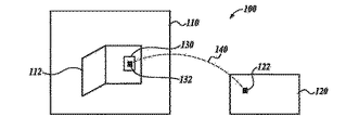
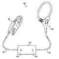
(1)電流を流す電気導体を有する電気機器に関する特性を測定し、測定した上記特性を表すデータを遠隔計算装置に伝送するように構成された試験装置と;上記電気導体からの電流を誘導するように構成された電流トランスを形成し、上記電気導体の周囲にクランプされるように構成された電流クランプと;誘導された上記電流を、上記試験装置に電力供給するのに利用可能な直流に変換するように構成された回路とを備えるシステム。
(2)上記電気機器の特性に基づいて信号を発生するように構成された検知器を更に備える概念1のシステム。
(3)上記特性は、上記電気機器の少なくとも一部の電気特性である概念2のシステム。
(4)上記電気機器の上記一部は、上記電気導体を含む概念3のシステム。
(5)上記電気機器の上記一部は、上記電気導体を含まない概念3のシステム。
(6)上記特性は、上記電気機器の環境特性、又は上記電気機器を保持する領域の環境特性である概念2のシステム。
(7)上記検知器は、上記試験装置の外部にあるか又は上記試験装置に結合される概念2のシステム。
(8)上記検知器は、上記試験装置の内部にある概念2のシステム。
(9)上記試験装置は、上記試験装置の電力供給に利用可能な1つ以上のバッテリを備える概念1のシステム。
(10)上記回路は、直流源の電圧及び1つ以上のバッテリの電圧に基づいて、上記直流源及び上記1つ以上のバッテリの一方から上記試験装置に電力を供給するように構成されている概念9のシステム。
(11)上記回路は、上記直流源の電圧及び1つ以上のバッテリの電圧の高い方に基づいて、上記直流源及び上記1つ以上のバッテリの一方から上記試験装置に電力を供給するように配置されたダイオードを備える概念10のシステム。
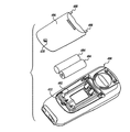
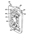
(12)上記試験装置は、上記1つ以上のバッテリ及びバッテリ区画カバーを保持するように構成されたバッテリ区画を備え、上記バッテリ区画カバーは、上記電力クランプを上記試験装置に電気的に結合するように構成されたコネクタを備える概念9のシステム。
(13)上記回路の少なくとも一部は、上記バッテリ区画カバー上に配置される概念12のシステム。
(14)上記回路は、上記直流源を用いて上記1つ以上のバッテリを再充電するように構成された概念9のシステム。
(15)上記回路は、同時に上記1つ以上のバッテリを再充電すると共に、上記直流源を用いて上記試験装置に電力を供給するように構成された概念14のシステム。
(16)上記電流クランプが上記電気導体から電流を誘導したかを示すように構成された指示器を更に備える概念1のシステム。
(17)上記指示器は、上記電流クランプ上の光素子、上記試験装置上の光素子、又は上記試験装置の表示器上のアイコンの少なくとも1つを備える概念16のシステム。
(18)上記電流クランプの大きさは、上記電気導体の大きさに基づいて決まる概念1のシステム。
(19)上記電気導体から誘導された電流は、上記電気導体により伝送される電流の1%以下である概念1のシステム。
(20)上記デコーダにより伝送される電流は、上記試験装置の最大定格電流よりも大きい概念1のシステム。
(21)上記試験装置は、少なくとも無線信号により上記遠隔計算装置に、上記測定した特性を表すデータを伝送するように更に構成された概念1のシステム。
(22)上記電流トランスは、非トロイダル電流トランスである概念1のシステム。
110、210:電気機器領域
112:パネル
120:モニタ・ステーション
122:受信機
130、220、320:試験装置
132:送信機
140:伝送手段
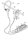
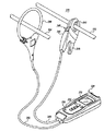
212、214:電気導体
216:機器
218:リード
222:表示器
224:ユーザ・インタフェース機構
226:指示器
230、330:検知器
232、248、332:ワイヤ
240、340:電流クランプ
242:非トロイダル電流トランス
244:ハンドル
246:操作部
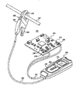
326、328:指示器
340:電流クランプ
400:試験装置
402:バッテリ区画
404、426:バッテリ
406、414:バッテリ区画カバー
408、416、422:タブ
410、418:ネジ
412:ねじ穴
420:コネクタ
424:プリント回路基板
504:整流器
518:試験装置用電力インレット(入口)
Claims (9)
- 電流を流す電気導体を有する電気機器に関する特性を測定し、測定した上記特性を表すデータを遠隔計算装置に伝送するように構成された試験装置と、
上記電気導体からの電流を誘導するように構成された電流トランスを形成し、上記電気導体の周囲にクランプされるように構成された電流クランプと、
誘導された上記電流を、上記試験装置に電力供給するのに利用可能な直流に変換するように構成された回路と
を備えるシステム。 - 上記電気機器の特性に基づいて信号を発生するように構成された検知器を更に備える請求項1のシステム。
- 上記試験装置は、上記試験装置の電力供給に利用可能な1つ以上のバッテリを備える請求項1のシステム。
- 上記電流クランプが上記電気導体から電流を誘導したかを示すように構成された指示器を更に備える請求項1のシステム。
- 上記電流クランプの大きさは、上記電気導体の大きさに基づいて決まる請求項1のシステム。
- 上記電気導体から誘導された電流は、上記電気導体により伝送される電流の1%以下である請求項1のシステム。
- 上記デコーダにより伝送される電流は、上記試験装置の最大定格電流よりも大きい請求項1のシステム。
- 上記試験装置は、少なくとも無線信号により上記遠隔計算装置に、上記測定した特性を表すデータを伝送するように更に構成された請求項1のシステム。
- 上記電流トランスは、非トロイダル電流トランスである請求項1のシステム。
Applications Claiming Priority (2)
| Application Number | Priority Date | Filing Date | Title |
|---|---|---|---|
| US14/595576 | 2015-01-13 | ||
| US14/595,576 US9698609B2 (en) | 2015-01-13 | 2015-01-13 | Testing device power induced by current transformer |
Publications (2)
| Publication Number | Publication Date |
|---|---|
| JP2016138880A true JP2016138880A (ja) | 2016-08-04 |
| JP2016138880A5 JP2016138880A5 (ja) | 2019-02-28 |
Family
ID=55129671
Family Applications (1)
| Application Number | Title | Priority Date | Filing Date |
|---|---|---|---|
| JP2016004805A Ceased JP2016138880A (ja) | 2015-01-13 | 2016-01-13 | 電流トランスによる試験装置用電力誘導システム |
Country Status (4)
| Country | Link |
|---|---|
| US (1) | US9698609B2 (ja) |
| EP (1) | EP3045922A1 (ja) |
| JP (1) | JP2016138880A (ja) |
| CN (1) | CN105785162A (ja) |
Cited By (1)
| Publication number | Priority date | Publication date | Assignee | Title |
|---|---|---|---|---|
| JP2021527215A (ja) * | 2018-06-11 | 2021-10-11 | テクトロニクス・インコーポレイテッドTektronix,Inc. | タッチスクリーンを有する試験測定プローブ |
Families Citing this family (5)
| Publication number | Priority date | Publication date | Assignee | Title |
|---|---|---|---|---|
| US10132841B2 (en) * | 2017-02-08 | 2018-11-20 | Peaceful Thriving Enterprise Co., Ltd. | Clamp meter |
| US10935579B2 (en) * | 2018-06-18 | 2021-03-02 | Atlas Copco Airpower, Naamloze Vennootschap | Current sensor |
| USD923500S1 (en) * | 2020-01-08 | 2021-06-29 | ShenZhen AIMOmeter Co., Ltd. | Multimeter |
| CN111952043A (zh) * | 2020-08-10 | 2020-11-17 | 广东电网有限责任公司 | 一种利用柔性互感器从电缆取能的便携式电源装置 |
| US11693033B2 (en) | 2021-09-02 | 2023-07-04 | Fluke Corporation | Sensor probe with combined non-contact sensor and a Rogowski coil |
Citations (4)
| Publication number | Priority date | Publication date | Assignee | Title |
|---|---|---|---|---|
| US20110012587A1 (en) * | 2009-07-17 | 2011-01-20 | Fluke Corporation | Clamp-on multimeters including a rogowski coil for measuring alternating current in a conductor |
| WO2014129817A1 (ko) * | 2013-02-21 | 2014-08-28 | ㈜테라에너지시스템 | 센서용 ct와 발전용ct가 선로 상에 병렬로 분리 설치되는 전류 변성 시스템, 및 이를 무선 통신망으로 관리하는 통합 시스템 |
| CN203929848U (zh) * | 2013-05-21 | 2014-11-05 | 株式会社碧陆斯 | 电流监测仪及利用其的电流监测系统 |
| JP2015154501A (ja) * | 2014-02-10 | 2015-08-24 | 東京電力株式会社 | 自己給電式電流測定装置 |
Family Cites Families (19)
| Publication number | Priority date | Publication date | Assignee | Title |
|---|---|---|---|---|
| FR2788343B1 (fr) * | 1999-01-12 | 2001-02-16 | Universal Technic | Pince de mesure d'un courant circulant dans des conducteurs |
| US7633262B2 (en) * | 2005-03-11 | 2009-12-15 | Lindsey Manufacturing Company | Power supply for underground and pad mounted power distribution systems |
| US20070007968A1 (en) | 2005-07-08 | 2007-01-11 | Mauney William M Jr | Power monitoring system including a wirelessly communicating electrical power transducer |
| US20090015239A1 (en) * | 2007-03-01 | 2009-01-15 | Georgiou George E | Transmission Line Sensor |
| CN201156056Y (zh) * | 2007-07-31 | 2008-11-26 | 保定科远电力设备有限公司 | 一种用于高压高空线路在线测量电流的钳形表 |
| US9383394B2 (en) | 2007-11-02 | 2016-07-05 | Cooper Technologies Company | Overhead communicating device |
| US20100253318A1 (en) | 2009-02-02 | 2010-10-07 | Thomas Sr Kirk | High voltage to low voltage inductive power supply with current sensor |
| US8203328B2 (en) * | 2009-03-12 | 2012-06-19 | Consolidated Edison Company Of New York, Inc. | Current measuring device |
| US7750621B1 (en) | 2009-07-17 | 2010-07-06 | Chung Instrument Electronics Industrial Co., Ltd. | Clamp meter for measuring consumption of current and power of electrical product |
| US8330449B2 (en) * | 2009-07-20 | 2012-12-11 | Fluke Corporation | Clamp-on multimeters including a Rogowski coil for measuring alternating current in a conductor |
| CN102625916A (zh) * | 2009-07-18 | 2012-08-01 | 纳克斯伦特有限责任公司 | 电力系统传感器装置、电力系统监测方法以及电力系统监测系统 |
| CN101706530B (zh) * | 2009-10-30 | 2012-06-27 | 浙江万马电缆股份有限公司 | 一种电缆导体直流电阻在线检测装置及方法 |
| US8564298B2 (en) | 2009-12-04 | 2013-10-22 | University Of South Carolina | Non-intrusive energy harvesting systems and methods |
| US9697724B2 (en) * | 2010-09-22 | 2017-07-04 | Hubbell Incorporated | Transmission line measuring device and method for connectivity and monitoring |
| US8587261B2 (en) | 2011-06-02 | 2013-11-19 | Electric Fuel Battery Corporation | Lightweight power system for continuously charging multiple battery powered devices carried by a dismounted soldier |
| FR2982665B1 (fr) * | 2011-11-10 | 2014-08-29 | Schneider Electric Ind Sas | Systeme de mesure de grandeurs physiques, dispositif d'alimentation et procede de configuration associes a un tel systeme de mesure |
| AP2014008093A0 (en) | 2012-05-29 | 2014-11-30 | Awesense Wireless Inc | System, method and device for providing a stable power source without the use of direct connection to an AC or DC source |
| US9198500B2 (en) * | 2012-12-21 | 2015-12-01 | Murray W. Davis | Portable self powered line mountable electric power line and environment parameter monitoring transmitting and receiving system |
| CN105510671B (zh) * | 2014-09-24 | 2020-10-30 | 福禄克公司 | 钳表及钳状探头 |
-
2015
- 2015-01-13 US US14/595,576 patent/US9698609B2/en active Active
-
2016
- 2016-01-13 JP JP2016004805A patent/JP2016138880A/ja not_active Ceased
- 2016-01-13 CN CN201610020481.1A patent/CN105785162A/zh active Pending
- 2016-01-13 EP EP16151112.6A patent/EP3045922A1/en not_active Withdrawn
Patent Citations (4)
| Publication number | Priority date | Publication date | Assignee | Title |
|---|---|---|---|---|
| US20110012587A1 (en) * | 2009-07-17 | 2011-01-20 | Fluke Corporation | Clamp-on multimeters including a rogowski coil for measuring alternating current in a conductor |
| WO2014129817A1 (ko) * | 2013-02-21 | 2014-08-28 | ㈜테라에너지시스템 | 센서용 ct와 발전용ct가 선로 상에 병렬로 분리 설치되는 전류 변성 시스템, 및 이를 무선 통신망으로 관리하는 통합 시스템 |
| CN203929848U (zh) * | 2013-05-21 | 2014-11-05 | 株式会社碧陆斯 | 电流监测仪及利用其的电流监测系统 |
| JP2015154501A (ja) * | 2014-02-10 | 2015-08-24 | 東京電力株式会社 | 自己給電式電流測定装置 |
Cited By (2)
| Publication number | Priority date | Publication date | Assignee | Title |
|---|---|---|---|---|
| JP2021527215A (ja) * | 2018-06-11 | 2021-10-11 | テクトロニクス・インコーポレイテッドTektronix,Inc. | タッチスクリーンを有する試験測定プローブ |
| JP7402597B2 (ja) | 2018-06-11 | 2023-12-21 | テクトロニクス・インコーポレイテッド | タッチスクリーンを有する試験測定プローブ |
Also Published As
| Publication number | Publication date |
|---|---|
| EP3045922A1 (en) | 2016-07-20 |
| US9698609B2 (en) | 2017-07-04 |
| US20160204617A1 (en) | 2016-07-14 |
| CN105785162A (zh) | 2016-07-20 |
Similar Documents
| Publication | Publication Date | Title |
|---|---|---|
| JP2016138880A (ja) | 電流トランスによる試験装置用電力誘導システム | |
| US9735588B2 (en) | Power source system with multiple electrical outputs | |
| JP5235908B2 (ja) | 電力計測システム、機器制御システム | |
| JP5976121B2 (ja) | 電源開閉装置用小型接続システム | |
| KR101404102B1 (ko) | 활선 경보장치를 포함하는 배전반 및 이에 이용되는 부스바의 복합 센서 | |
| US4717872A (en) | Device for monitoring consumption of electrical power | |
| KR101606704B1 (ko) | 활선표시장치 및 보호계전기 동작 음성경보장치를 구비한 수배전반 | |
| KR101979631B1 (ko) | 무선온도감지장치 | |
| US10079619B2 (en) | Wireless batteryless data processing unit | |
| EP3318884B1 (en) | Power monitoring probe for monitoring power distribution in an electrical system | |
| KR20150069952A (ko) | 벽에 설치 가능한 무선전력 전송장치 | |
| KR101362792B1 (ko) | 활선 경보장치를 포함하는 배전반 및 이에 이용되는 부스바의 에폭시 애자 | |
| JP2016138880A5 (ja) | ||
| WO2015188593A1 (zh) | 一种交直流电流无线监测设备 | |
| JP2001004672A (ja) | 可搬型光電流計 | |
| JP2011217572A (ja) | 分電盤 | |
| KR20200006916A (ko) | 무선형 활선경보장치 | |
| WO2015045346A1 (ja) | 表示機能付き分電盤 | |
| CN203323900U (zh) | 电磁能收集型无线测温模块 | |
| TW201230561A (en) | Plug for a wiring duct | |
| JP2016163362A (ja) | 分電盤 | |
| JP2016163363A (ja) | 分電盤 | |
| US6577115B1 (en) | Apparatus with separated conductors | |
| JP2014025707A (ja) | 電流計測部材 | |
| KR101454121B1 (ko) | 직류피뢰기의 열화진단을 위한 누설전류 검출장치 |
Legal Events
| Date | Code | Title | Description |
|---|---|---|---|
| A521 | Request for written amendment filed |
Free format text: JAPANESE INTERMEDIATE CODE: A523 Effective date: 20190111 |
|
| A621 | Written request for application examination |
Free format text: JAPANESE INTERMEDIATE CODE: A621 Effective date: 20190111 |
|
| A977 | Report on retrieval |
Free format text: JAPANESE INTERMEDIATE CODE: A971007 Effective date: 20191113 |
|
| A131 | Notification of reasons for refusal |
Free format text: JAPANESE INTERMEDIATE CODE: A131 Effective date: 20191203 |
|
| A521 | Request for written amendment filed |
Free format text: JAPANESE INTERMEDIATE CODE: A523 Effective date: 20200228 |
|
| A01 | Written decision to grant a patent or to grant a registration (utility model) |
Free format text: JAPANESE INTERMEDIATE CODE: A01 Effective date: 20200407 |
|
| A045 | Written measure of dismissal of application [lapsed due to lack of payment] |
Free format text: JAPANESE INTERMEDIATE CODE: A045 Effective date: 20200901 |