JP2016135190A - Endoscope reprocessor - Google Patents
Endoscope reprocessor Download PDFInfo
- Publication number
- JP2016135190A JP2016135190A JP2015011523A JP2015011523A JP2016135190A JP 2016135190 A JP2016135190 A JP 2016135190A JP 2015011523 A JP2015011523 A JP 2015011523A JP 2015011523 A JP2015011523 A JP 2015011523A JP 2016135190 A JP2016135190 A JP 2016135190A
- Authority
- JP
- Japan
- Prior art keywords
- fluid
- unit
- endoscope
- accessory
- accessory case
- Prior art date
- Legal status (The legal status is an assumption and is not a legal conclusion. Google has not performed a legal analysis and makes no representation as to the accuracy of the status listed.)
- Pending
Links
Images


Abstract
Description
本発明は、内視鏡から取り外した付属品を収容する付属品ケースを有し、内視鏡とともに付属品にリプロセスを施す内視鏡リプロセッサに関する。 The present invention relates to an endoscope reprocessor that has an accessory case that accommodates an accessory removed from an endoscope and reprocesses the accessory together with the endoscope.
医療分野において使用される内視鏡は、使用後に例えば洗浄液、消毒液および空気等の流体を用いたリプロセスが施される。内視鏡に対して自動的に流体を用いたリプロセスを施す装置として、例えば特開2011−206156号公報に開示されているような内視鏡リプロセッサが知られている。 Endoscopes used in the medical field are subjected to reprocessing using fluids such as cleaning liquid, disinfecting liquid and air after use. For example, an endoscope reprocessor as disclosed in Japanese Patent Application Laid-Open No. 2011-206156 is known as an apparatus that automatically performs reprocessing using a fluid on an endoscope.
特開2011−206156号公報に開示されている内視鏡リプロセッサは、使用後の内視鏡から取り外した例えば吸引ボタン、送気送水ボタン等の付属品を収容する付属品ケースと、付属品ケース内にリプロセス用の流体を導入する構成を有しており、内視鏡とともに付属品にも流体を用いたリプロセスを施す。 An endoscope reprocessor disclosed in Japanese Patent Application Laid-Open No. 2011-206156 includes an accessory case that accommodates accessories such as a suction button and an air / water supply button that are removed from the endoscope after use, and an accessory. The reprocessing fluid is introduced into the case, and the reprocessing using the fluid is applied to the accessory as well as the endoscope.
従来の内視鏡リプロセッサでは、付属品ケースの内部に付属品が収容されていない場合であっても、付属品ケースの内部にリプロセス用の流体を導入する工程が実行される。また、従来の内視鏡リプロセッサでは、内視鏡の管路等の内部に流体を導入する場合と、付属品ケースの内部に流体を導入する場合とで、同一のポンプおよびエアコンプレッサを用いており、流路を切り替えることで流体を導入する先を変更している。このような構成を有する従来の内視鏡リプロセッサでは、内視鏡の内部に流体を導入する工程と、付属品ケースの内部に流体を導入する工程とを同時に実行することができないため、付属品ケースの内部に付属品が収容されていない場合に付属品ケースの内部に流体を導入する工程を実行すると、無駄な時間が生じてしまう。 In a conventional endoscope reprocessor, even when no accessory is accommodated in the accessory case, a step of introducing a reprocessing fluid into the accessory case is executed. Also, in the conventional endoscope reprocessor, the same pump and air compressor are used for introducing fluid into the endoscope duct and the like and for introducing fluid into the accessory case. The destination of the fluid is changed by switching the flow path. In the conventional endoscope reprocessor having such a configuration, the step of introducing the fluid into the endoscope and the step of introducing the fluid into the accessory case cannot be performed at the same time. If a process of introducing a fluid into the accessory case is performed when no accessory is accommodated in the accessory case, useless time is generated.
本発明は、上述した問題点を解決するものであって、内視鏡リプロセッサにおいて、付属品へのリプロセスが不要である場合に内視鏡に対してリプロセスを施すのに要する時間を短縮することを目的とする。 The present invention solves the above-described problems, and in an endoscope reprocessor, when it is not necessary to reprocess an accessory, the time required for performing reprocessing on the endoscope is reduced. The purpose is to shorten.
本発明の一態様による内視鏡リプロセッサは、内視鏡の内部に連通して前記内視鏡の内部に流体を導入する第1流体導入部と、前記内視鏡から取り外した付属品を収容する付属品ケースと、前記付属品ケースの内部に前記付属品が配置されているか否かを検知する検知部と、前記付属品ケースの内部に連通して前記付属品ケースの内部に流体を導入する第2流体導入部と、流体を送出する流体送出部と、前記流体送出部、前記第1流体導入部および前記第2流体導入部に接続されており、前記流体送出部から送出された流体を、前記第1流体導入部および前記第2流体導入部に案内し、前記流体送出部から送出された流体のうちの少なくとも前記第2流体導入部に流入する流体の流量を制御する切替部と、前記検知部および前記切替部に接続されており、前記検知部が前記付属品ケースの内部に前記付属品が配置されていると検知した場合には、前記付属品ケースの内部に所定時間流体を導入するよう前記切替部を制御する制御部と、を含む。 An endoscope reprocessor according to an aspect of the present invention includes: a first fluid introduction unit that communicates with an interior of an endoscope to introduce a fluid into the endoscope; and an accessory that is removed from the endoscope. An accessory case to be accommodated, a detection unit for detecting whether or not the accessory is arranged in the accessory case, and a fluid in the accessory case in communication with the accessory case. The second fluid introduction part to be introduced, the fluid delivery part to deliver fluid, the fluid delivery part, the first fluid introduction part and the second fluid introduction part are connected to each other and delivered from the fluid delivery part A switching unit that guides the fluid to the first fluid introduction unit and the second fluid introduction unit and controls the flow rate of the fluid flowing into at least the second fluid introduction unit out of the fluid delivered from the fluid delivery unit. And connected to the detection unit and the switching unit And when the detection unit detects that the accessory is disposed inside the accessory case, the switching unit is controlled to introduce a fluid into the accessory case for a predetermined time. And a control unit.
本発明によれば、内視鏡リプロセッサにおいて、付属品へのリプロセスが不要である場合に内視鏡に対してリプロセスを施すのに要する時間を短縮することができる。 ADVANTAGE OF THE INVENTION According to this invention, when the reprocessing to an accessory is unnecessary in an endoscope reprocessor, the time required to perform a reprocess with respect to an endoscope can be shortened.
以下に、本発明の好ましい形態について図面を参照して説明する。なお、以下の説明に用いる各図においては、各構成要素を図面上で認識可能な程度の大きさとするため、構成要素毎に縮尺を異ならせてあるものであり、本発明は、これらの図に記載された構成要素の数量、構成要素の形状、構成要素の大きさの比率、および各構成要素の相対的な位置関係のみに限定されるものではない。 Hereinafter, preferred embodiments of the present invention will be described with reference to the drawings. In the drawings used for the following description, the scale of each component is made different in order to make each component recognizable on the drawing. It is not limited only to the quantity of the component described in (1), the shape of the component, the ratio of the size of the component, and the relative positional relationship of each component.
以下に、本発明の実施形態の一例を説明する。内視鏡リプロセッサ1は、内視鏡および内視鏡の付属品の少なくとも一方に対して、洗浄液、消毒液および空気等の流体を用いたリプロセスを施す装置である。 Hereinafter, an example of an embodiment of the present invention will be described. The endoscope reprocessor 1 is a device that performs reprocessing using a fluid such as a cleaning liquid, a disinfecting liquid, and air on at least one of an endoscope and an accessory of the endoscope.
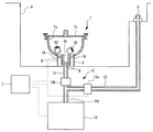
図1に示すように、内視鏡リプロセッサ1は、制御部2、電源装置3、処理槽4、第1流体導入部5、第2流体導入部6、付属品ケース7、検知部8、流体送出部10、および切替部13を含む。
As shown in FIG. 1, the endoscope reprocessor 1 includes a control unit 2, a power supply device 3, a processing tank 4, a first
制御部2は、内視鏡リプロセッサ1の後述する各構成要素の動作を、所定のプログラムに基づいて制御する装置であり、例えば演算装置、記憶装置、補助記憶装置および入出力装置等を具備して構成されるコンピュータを含む。制御部2の制御については後述する。 The control unit 2 is a device that controls the operation of each component described later of the endoscope reprocessor 1 based on a predetermined program, and includes, for example, an arithmetic device, a storage device, an auxiliary storage device, an input / output device, and the like. Computer configured. The control of the control unit 2 will be described later.
電源装置3は、制御部2やその他の内視鏡リプロセッサ1の構成要素に電力を供給する。電源装置3は、商用電源等の外部から得た電力を各構成要素に供給する構成であってもよいし、一次電池、二次電池又は発電装置等の自らが電力を生じる構成であってもよい。 The power supply device 3 supplies power to the control unit 2 and other components of the endoscope reprocessor 1. The power supply device 3 may be configured to supply electric power obtained from the outside such as a commercial power supply to each component, or may be configured such that a power source itself such as a primary battery, a secondary battery, or a power generation device generates power. Good.
処理槽4は、上方に向かって開口する開口部を有した凹形状の部材であり、内部に内視鏡50および後述する付属品ケース7を配置することができる。処理槽4は、内部に液体を貯留可能に構成されている。
The processing tank 4 is a concave member having an opening that opens upward, and an
処理槽4の上部には、開口部を開閉する蓋部材4aが設けられている。処理槽4の下部には、循環口4bおよび排液口4cが設けられている。循環口4bおよび排液口4cは、処理槽4の底面又は底面近傍において開口する開口部である。循環口4bは、後述する循環管路24に連通している。
A
排液口4cは、排液管路29に連通している。排液管路29には、排液管路29を開閉する排液弁30が設けられている。図示しないが、排液弁30は、制御部2に接続されている。排液弁30を開状態とすることにより、処理槽4内の液体は、排液口4cおよび排液管路29を通って内視鏡リプロセッサ1の外部に排出される。
The
また、処理槽4の内部には、処理液導入ノズル4d、循環ノズル4e、第1流体導入部5および第2流体導入部6が設けられている。
In addition, a treatment liquid introduction nozzle 4d, a circulation nozzle 4e, a first
処理液導入ノズル4dは、処理液管路21を介して、液体である処理液を貯留する処理液貯留部20に連通している。処理液管路21には、処理液を処理液貯留部20から処理液導入ノズル4dに向かって移送する処理液ポンプ22が設けられている。図示しないが、処理液ポンプ22は、制御部2に接続されている。処理液ポンプ22を稼働することによって、処理液貯留部20内の処理液が処理液導入ノズル4dから吐出され、処理槽4内に導入される。
The processing liquid introduction nozzle 4 d communicates with the processing
なお、処理液導入ノズル4d、処理液貯留部20、処理液管路21および処理液ポンプ22の組み合わせを含む構成は、リプロセスに用いる処理液の種類の数に応じて配設される。例えば、リプロセスに洗浄液および消毒液の2種類の処理液を用いる場合には、内視鏡リプロセッサ1は、処理液貯留部20、処理液管路21および処理液ポンプ22の組み合わせを、洗浄液用および消毒液用として2つ有する。
The configuration including the combination of the processing liquid introduction nozzle 4d, the processing
循環ノズル4eは、循環管路24を介して循環口4bと連通している。循環ノズル4eと循環管路24との間には、三方弁26が配設されている。三方弁26には、水導入管路27の一端が接続されている。
The circulation nozzle 4 e communicates with the
図示しないが、三方弁26は、制御部2に接続されている。三方弁26は、循環ノズル4eと循環管路24とを連通した状態、および循環ノズル4eと水導入管路27とを連通した状態、を切り替えることができる。
Although not shown, the three-
水導入管路27の他端は、水導入弁28に接続されている。水導入弁28は、液体である水道水を吐出する水道栓40にホース41を介して連通する。図示しないが、水導入弁28は、制御部2に接続されている。水導入弁28を開状態とし、三方弁26を循環ノズル4eと水導入管路27とを連通した状態とした場合には、水道水が循環ノズル4eから吐出され、処理槽4内に導入される。
The other end of the
循環管路24には、循環ポンプ25が設けられている。図示しないが、循環ポンプ25は、制御部2に接続されている。三方弁26を循環管路24と循環ノズル4eとを連通した状態とし、循環ポンプ25を稼働することによって、処理槽4内の液体は、循環口4bから吸い出された後に、循環管路24および循環ノズル4eを経由して処理槽4内に戻る。すなわち、循環ポンプ25の稼働により、処理槽4内と循環管路24内を通って循環する液体の流れが生じる。
A
第1流体導入部5は、内視鏡50の内部に連通し、内視鏡50の内部に処理液や水道水等の液体および空気等のリプロセスに用いる流体を導入する部位である。流体は、後述する流体送出部10から送出される。内視鏡50の内部とは、例えば内視鏡50が備える管路である。
The first
本実施形態では一例として、第1流体導入部5は、接続チューブ51を介して内視鏡50の内部に連通する。接続チューブ51の一端は内視鏡50に着脱可能であり、他端は第1流体導入部5に着脱可能である。なお、第1流体導入部5は、接続チューブ51を介さず内視鏡50の内部に直接的に接続される構成であってもよい。
In the present embodiment, as an example, the first
第2流体導入部6は、後述する付属品ケース7の内部に連通し、付属品ケース7の内部に処理液や水道水等の液体および空気等のリプロセスに用いる流体を導入する部位である。流体は、後述する流体送出部10から送出される。
The second fluid introduction part 6 is a part that communicates with the interior of an
図2に示すように、付属品ケース7は、内部に内視鏡50から取り外した付属品52を収容する空間を有する。付属品52とは、例えば、吸引ボタン、送気送水ボタン、鉗子栓等である。付属品ケース7には、内部に付属品52を出し入れするための開口部7a、および内部と第1流体導入部5とを連通する接続口7bが設けられている。開口部7aには、蓋7cを取り付けることができる。蓋7cは、付属品ケース7の内部に配置された付属品52が外部に抜け出ることを防止し、かつ流体が通過する開口を有する。第2流体導入部6から付属品ケース7内に導入された流体は、付属品ケース7内において付属品52を撹拌した後に、蓋7cを通過して処理槽4内に流れ出す。付属品ケース7は、第2流体導入部6に固定されていてもよいし、第2流体導入部6に着脱可能であってもよい。
As shown in FIG. 2, the
図示する本実施形態では、付属品ケース7は鉢状の容器であり、開口部7aに網目状の蓋7cが装着される。接続口7bは、付属品ケース7の底部に設けられている。なお、付属品ケース7の形状や、開口部7aおよび接続口7bの配置位置は本実施形態に限られるものではない。
In the illustrated embodiment, the
検知部8は、第2流体導入部6に連通している付属品ケース7の内部に付属品52が配置されているか否かを検知する。検知部8は、制御部2に接続されており、検知部8による検知結果の情報は制御部2に入力される。
The detection unit 8 detects whether or not the accessory 52 is disposed inside the
検知部8の構成は、付属品52の存在の有無を検知可能なものであれば特に限定されるものではない。例えば検知部8は、近接センサによって構成される。近接センサは、例えば可視光や赤外光等の電磁波を付属品ケース7内に発信する発信部と、発信部から発信された電磁波を感知する受信部とを備え、受信部における付属品52による前記電磁波の反射又は遮蔽による受信強度の変化に基づいて、付属品52の存在の有無を検知する、いわゆるフォトセンサと称される電磁波センサの形態が知られている。
The configuration of the detection unit 8 is not particularly limited as long as the presence / absence of the accessory 52 can be detected. For example, the detection unit 8 is configured by a proximity sensor. The proximity sensor includes, for example, a transmitter that transmits electromagnetic waves such as visible light and infrared light into the
本実施形態では一例として、検知部8は、電磁波センサを含む。付属品ケース7には、電磁波センサが送受信する電磁波を透過するための窓部7dが設けられている。窓部7dは、貫通孔であってもよいし、例えば透明な材料のような電磁波センサが送受信する電磁波を透過する材料によって塞がれた孔であってもよい。
In the present embodiment, as an example, the detection unit 8 includes an electromagnetic wave sensor. The
言い換えれば、検知部8は、処理槽4内において付属品ケース7を第2流体導入部6に連通させた状態において、付属品ケース7の外部から窓部7dを通じて電磁波を送受信する位置に配置されている。なお、付属品ケース7の全体が、例えば透明な材料のような電磁波センサが送受信する電磁波を透過する材料によって構成されていてもよい。
In other words, the detection unit 8 is arranged at a position for transmitting and receiving electromagnetic waves from the outside of the
なお、検知部8に含まれる近接センサは、超音波を送受信する形態や、静電容量の変化を検知する形態等、他の形態のものであってもよい。また、付属品52に磁性体が埋め込まれている場合には、検知部8に含まれる近接センサは、磁界の変化を検知する形態のものであってもよい。
The proximity sensor included in the detection unit 8 may have other forms such as a form for transmitting and receiving ultrasonic waves and a form for detecting a change in capacitance. Further, when a magnetic material is embedded in the
また、検知部8は、例えば付属品ケース7内を撮影するカメラと、前記カメラによって撮影された画像を処理する画像処理装置を備え、画像認識によって付属品52の存在の有無を検知する構成であってもよい。また、付属品52がRFIDタグを備える場合には、検知部8は、RFIDリーダを備え、RFIDタグとの通信の可否に基づいて付属品52の存在の有無を検知する構成であってもよい。
The detection unit 8 includes, for example, a camera that captures the inside of the
流体送出部10は、流体を送出管路10cに送出する部位である。送出管路10cは、後述する切替部13と流体送出部10とを連通する。流体送出部10が送出する流体の種類は特に限定されるものではなく、流体は、液体であってもよいし、気体であってもよいし、液体と気体が混合したものであってもよい。また、流体送出部10が送出する流体の種類は、1つであってもよいし、複数であってもよい。
The
また、流体送出部10への流体の供給の形態は特に限定されるものではない。流体送出部10が送出する流体は、周囲の空気や水道水等の内視鏡リプロセッサ1の外部から供給されるものであってもよいし、処理槽4や処理液貯留部20等の内視鏡リプロセッサ1の内部に貯留されているものであってもよい。
Moreover, the form of supply of the fluid to the
本実施形態では一例として、流体送出部10は、送液ポンプ10aおよびエアコンプレッサ10bを含む。送液ポンプ10aは、分岐管路10dに設けられている。分岐管路10dは、循環管路24の循環口4bから循環ポンプ25までの間の区間と、送出管路10cの一端とを連通する。図示しないが、送液ポンプ10aは、制御部2に接続されている。送液ポンプ10aを稼働することによって、処理槽4内に貯留されている液体が、循環口4b、循環管路24および分岐管路10dを経由して送出管路10c内に送出される。処理槽4内に貯留されている液体とは、本実施形態では例えば水道水又は処理液である。
In the present embodiment, as an example, the
エアコンプレッサ10bは、吸気管路10eに設けられている。吸気管路10eは、一端が大気に開放され、他端が送出管路10cに接続されている。図示しないが、エアコンプレッサ10bは、制御部2に接続されている。エアコンプレッサ10bを稼働することによって、空気が吸気管路10eを経由して送出管路10c内に送出される。流体送出部10は、アルコール水溶液を送出管路10cに送出する構成を有していてもよい。
The
なお、本実施形態の流体送出部10は、流体を所定の圧力で送出する構成である送液ポンプ10aおよびエアコンプレッサ10bを備えるが、流体が内視鏡リプロセッサ1の外部から所定の圧力で供給される場合には、流体送出部10はこれらの流体を所定の圧力で送出する構成を備えていなくともよい。この場合には、流体送出部10は、外部から所定の圧力で供給された流体の送出管路10cへの流入を制御する弁機構を含む。
In addition, although the
切替部13は、流体送出部10、第1流体導入部5および第2流体導入部6に接続されており、流体送出部10から送出された流体の第2流体導入部6への流入量を制御する。切替部13は、制御部2に接続されており、制御部2から出力される指令信号に基づいて動作する。
The switching
切替部13の配置位置としては、例えば第1管路11、第2管路12、または第1管路11と第2管路12とが交わる部分が挙げられる。切替部13はこれらのうち1箇所に配置されていてもよいし、複数個所に亘って配置されていてもよいし、切替部13が複数存在して複数の箇所にそれぞれ配置されていてもよい。
Examples of the arrangement position of the switching
例えば、第1管路11または第2管路12に切替部13が配置される場合、切替部13として管路の開放と閉鎖とを切り替える開閉弁を用いることができる。また例えば、第1管路11と第2管路12とが交わる部分に切替部13が配置される場合、切替部13として流体の流路を切り替える三方弁を用いることができる。
For example, when the switching
切替部13は、第2流体導入部6に流入する流体の流量を制御する構成であれば特に限定されるものではない。本実施形態では一例として、切替部13は、流体送出部10から第2流体導入部6に流体が流入する状態と、第2流体導入部6への流体の流入を遮断する状態と、の2つの状態を切り替える。なお、切替部13が、流体送出部10から第2流体導入部6に流体を流入させる状態にある場合において、第1流体導入部5への流体の流入は行われてもよいし、遮断されてもよい。
The switching
ここでいう流量の制御とは、流体を第2流体導入部6に導入するか導入しないかの制御であってもよいし、第2流体導入部6への流体の導入量を最小値から最大値まで変化させてゆく制御のいずれであってもよい。前記最小値とは例えば導入量ゼロである。 The control of the flow rate here may be a control of whether or not the fluid is introduced into the second fluid introduction unit 6 or the amount of the fluid introduced into the second fluid introduction unit 6 may be increased from a minimum value to a maximum value. Any of the control to change to the value may be used. The minimum value is, for example, zero introduction amount.
具体的には、図2に示すように、本実施形態の切替部13は、第1流体導入部5と流体送出部10の送出管路10cとを連通する第1管路11と、第2流体導入部6と流体送出部10の送出管路10cとを連通する第2管路12と、第1管路11を開閉する電磁開閉弁13aと、第2管路12に設けられたリリーフ弁13bと、を含む。電磁開閉弁13aは、制御部2に接続されており、制御部2から出力される指令信号に基づいて動作する。
Specifically, as shown in FIG. 2, the switching
リリーフ弁13bは、送出管路10c側の流体の圧力が所定の値以下である場合には第2管路12を閉塞し、送出管路10c側の流体の圧力が所定の値を超えた場合に第2管路12を開状態とする。
The
流体送出部10から流体を送出し、かつ電磁開閉弁13aが開状態である場合には、送出管路10c内の流体の圧力はリリーフ弁13bが開状態となる値よりも低い。したがって、電磁開閉弁13aが開状態である場合には、第2管路12がリリーフ弁13bによって閉塞されるため、流体送出部10から送出された流体は、第1管路11を通って第1流体導入部5のみに流入する。
When fluid is delivered from the
一方、流体送出部10から流体を送出し、かつ電磁開閉弁13aが閉状態である場合には、送出管路10c内の流体の圧力がリリーフ弁13bが開状態となる値を超える。したがって、電磁開閉弁13aが閉状態である場合には、第2管路12が開放されるため、流体送出部10から送出された流体は、第2管路12を通って第2流体導入部6のみに流入する。
On the other hand, when the fluid is delivered from the
次に、制御部2による内視鏡リプロセッサ1の制御について説明する。図3は、内視鏡リプロセッサ1において、内視鏡50の内部に流体を導入する流体送出処理のフローチャートである。
Next, control of the endoscope reprocessor 1 by the control unit 2 will be described. FIG. 3 is a flowchart of a fluid delivery process for introducing a fluid into the
流体送出処理の実行時には、図1に示すように、内視鏡50の内部と第1流体導入部5とが接続チューブ51を介して連通しており、かつ付属品ケース7の内部と第2流体導入部6とが連通している。本実施形態においては、内視鏡50の内部に液体である処理液又は水道水を導入する流体送出処理の実行には、図示しないが処理槽4内に液体が貯留されている。
When performing the fluid delivery process, as shown in FIG. 1, the interior of the
流体送出処理が実行される際の目的は特に限定されるものではなく、例えば内視鏡50の内部を洗浄および消毒するために処理液を内部に導入する場合、内視鏡50の内部を水道水ですすぐために内部に水道水を導入する場合、および内視鏡50の内部の水分を除去するために内部に空気を導入する場合、等において流体送出処理は実行される。
The purpose when the fluid delivery process is executed is not particularly limited. For example, when a processing liquid is introduced into the
流体送出処理では、まずステップS10において、検知部8により、第2流体導入部6に連通している付属品ケース7の内部に付属品52が配置されているか否かを検知する。そして、ステップS10において、検知部8が、付属品ケース7の内部に付属品52が配置されていることを検知した場合には、ステップS11に移行する。
In the fluid delivery process, first, in step S10, the detection unit 8 detects whether or not the accessory 52 is disposed inside the
ステップS11では、流体送出部10から流体を送出させるとともに、切替部13を動作させることによって、第1流体導入部5に、流体を所定の流量で所定の時間導入する。本実施形態では、切替部13の電磁開閉弁13aを開状態とした後に、流体送出部10を所定の時間動作させる。ステップS11の実行によって、内視鏡50の内部に流体が所定の流量で所定の時間導入される。
In step S11, the fluid is delivered from the
次にステップS12において、流体送出部10から流体を送出させるとともに、切替部13を動作させることによって、第2流体導入部6に、流体を所定の流量で所定の時間導入する。本実施形態では、切替部13の電磁開閉弁13aを閉状態とした後に、流体送出部10を所定の時間動作させる。ステップS12の実行によって、付属品ケース7の内部に流体が所定の流量で所定の時間導入される。
Next, in step S12, the fluid is delivered from the
なお、ステップS11およびステップS12の実行の順序は逆であってもよい。ステップS11およびステップS12の実行の後、流体送出処理を終了する。 Note that the order of execution of steps S11 and S12 may be reversed. After the execution of step S11 and step S12, the fluid delivery process is terminated.
なお、ステップS11およびステップS12は、それぞれを所定の回数に分割して交互に繰り返して実行される形態でもよい。ステップS11およびステップS12を交互に繰り返す場合には、それぞれを実行する回数は同一であってもよいし異なっていてもよい。 Note that steps S11 and S12 may be executed by dividing each of them into a predetermined number of times and repeating them alternately. When step S11 and step S12 are repeated alternately, the number of times each is executed may be the same or different.
一方、ステップS10において、検知部8が、付属品ケース7の内部に付属品52が配置されていないことを検知した場合には、ステップS21に移行する。ステップS21では、流体送出部10から流体を送出させるとともに、切替部13を動作させることによって、第1流体導入部5に、流体を所定の流量で所定の時間導入する。本実施形態では、切替部13の電磁開閉弁13aを開状態とした後に、流体送出部10を所定の時間動作させる。ステップS21の実行によって、内視鏡50の内部に流体が所定の流量で所定の時間導入される。
On the other hand, when the detection unit 8 detects in step S10 that the
ステップS21の実行の後、流体送出処理を終了する。 After execution of step S21, the fluid delivery process is terminated.
以上に説明したように、本実施形態の内視鏡リプロセッサ1は、内視鏡50の内部に連通して内視鏡50の内部に流体を導入する第1流体導入部5と、内視鏡50から取り外した付属品52を収容する付属品ケース7と、付属品ケース7の内部に付属品52が配置されているか否かを検知する検知部8と、付属品ケース7の内部に連通して付属品ケース7の内部に流体を導入する第2流体導入部6と、流体を送出する流体送出部10と、流体送出部10から送出された流体を、第1流体導入部5および第2流体導入部6に案内し、流体送出部10から送出された流体のうちの少なくとも第2流体導入部6に流入する流体の流量を制御する切替部と、検知部8および切替部13に接続されており、検知部8が付属品ケース7の内部に付属品52が配置されていると検知した場合には、付属品ケース7の内部に所定時間流体を導入するよう切替部13を制御する制御部2と、を含む。
As described above, the endoscope reprocessor 1 according to this embodiment includes the first
このような構成を有する本実施形態の内視鏡リプロセッサ1は、内視鏡50にリプロセスを施す際に、付属品ケース7の内部に付属品52が収容されている場合にのみ、付属品ケース7内にリプロセス用の流体を所定時間導入する。言い換えれば、本実施形態の内視鏡リプロセッサ1は、内視鏡50にリプロセスを施す際に、付属品ケース7の内部に付属品52が収容されていない場合には、付属品ケース7内にリプロセス用の流体を導入する工程を実行しない。
The endoscope reprocessor 1 of this embodiment having such a configuration is attached only when the
このため、本実施形態の内視鏡リプロセッサは、従来の内視鏡リプロセッサのように、付属品ケースの内部に付属品が収容されていない場合であっても、付属品ケースの内部にリプロセス用の流体を導入する工程が実行して無駄な時間を生じてしまうことがない。よって、本発明に係る内視鏡リプロセッサ1は、付属品52へのリプロセスが不要である場合に内視鏡50に対してリプロセスを施すのに要する時間を短縮することが可能である。
For this reason, the endoscope reprocessor according to the present embodiment is provided in the accessory case even when no accessory is accommodated in the accessory case, unlike the conventional endoscope reprocessor. The process of introducing the reprocessing fluid does not occur and wasteful time does not occur. Therefore, the endoscope reprocessor 1 according to the present invention can reduce the time required for reprocessing the
なお、本発明は、上述した実施形態に限られるものではなく、請求の範囲および明細書全体から読み取れる発明の要旨或いは思想に反しない範囲で適宜変更可能であり、そのような変更を伴う内視鏡リプロセッサもまた本発明の技術的範囲に含まれるものである。 Note that the present invention is not limited to the above-described embodiment, and can be appropriately changed without departing from the scope or spirit of the invention that can be read from the claims and the entire specification. Mirror reprocessors are also within the scope of the present invention.
前述のように、本発明は、内視鏡から取り外した付属品を収容する付属品ケースを有する内視鏡リプロセッサに適用可能である。 As described above, the present invention can be applied to an endoscope reprocessor having an accessory case that accommodates an accessory removed from the endoscope.
1 内視鏡リプロセッサ、
2 制御部、
3 電源装置、
4 処理槽、
4a 蓋部材、
4b 循環口、
4c 排液口、
4d 処理液導入ノズル、
4e 循環ノズル、
5 第1流体導入部、
6 第2流体導入部、
7 付属品ケース、
7a 開口部、
7b 接続口、
7c 蓋、
7d 窓部、
8 検知部、
10 流体送出部、
10a 送液ポンプ、
10b エアコンプレッサ、
10c 送出管路、
10d 分岐管路、
10e 吸気管路、
11 第1管路、
12 第2管路
13 切替部、
13a 電磁開閉弁、
13b リリーフ弁、
20 処理液貯留部、
21 処理液管路、
22 処理液ポンプ、
24 循環管路、
25 循環ポンプ、
26 三方弁、
27 水導入管路、
28 水導入弁、
29 排液管路、
30 排液弁、
40 水道栓、
41 ホース、
50 内視鏡、
51 接続チューブ、
52 付属品。
1 Endoscope reprocessor,
2 control unit,
3 power supply,
4 treatment tank,
4a lid member,
4b Circulation port,
4c drainage port,
4d treatment liquid introduction nozzle,
4e Circulation nozzle,
5 1st fluid introduction part,
6 Second fluid introduction part,
7 Accessory case,
7a opening,
7b connection port,
7c lid,
7d window,
8 detector,
10 Fluid delivery section,
10a Liquid feed pump,
10b Air compressor,
10c delivery line,
10d branch line,
10e Intake line,
11 First pipeline,
12
13a solenoid valve,
13b relief valve,
20 treatment liquid reservoir,
21 treatment liquid line,
22 treatment liquid pump,
24 circulation lines,
25 Circulation pump,
26 Three-way valve,
27 Water introduction line,
28 Water introduction valve,
29 drainage line,
30 drainage valve,
40 Water tap,
41 hose,
50 endoscope,
51 connection tube,
52 Accessories.
Claims (4)
前記内視鏡から取り外した付属品を収容する付属品ケースと、
前記付属品ケースの内部に前記付属品が配置されているか否かを検知する検知部と、
前記付属品ケースの内部に連通して前記付属品ケースの内部に流体を導入する第2流体導入部と、
前記第1流体導入部および前記第2流体導入部に連通しており、流体を送出する流体送出部と、
前記流体送出部、前記第1流体導入部および前記第2流体導入部に接続されており、前記流体送出部から送出された流体の前記第2流体導入部に流入する流量を制御する切替部と、
前記検知部および前記切替部に接続されており、前記検知部が前記付属品ケースの内部に前記付属品が配置されていると検知した場合には、前記付属品ケースの内部に所定時間流体を導入するよう前記切替部を制御する制御部と、
を含むことを特徴とする内視鏡リプロセッサ。 A first fluid introduction part that communicates with the interior of the endoscope and introduces fluid into the endoscope;
An accessory case for accommodating an accessory removed from the endoscope;
A detection unit for detecting whether or not the accessory is arranged inside the accessory case;
A second fluid introduction part that communicates with the interior of the accessory case and introduces fluid into the accessory case;
A fluid delivery section that communicates with the first fluid introduction section and the second fluid introduction section and delivers a fluid;
A switching unit that is connected to the fluid delivery unit, the first fluid introduction unit, and the second fluid introduction unit, and that controls a flow rate of the fluid delivered from the fluid delivery unit to flow into the second fluid introduction unit; ,
Connected to the detection unit and the switching unit, and when the detection unit detects that the accessory is disposed inside the accessory case, fluid is supplied to the accessory case for a predetermined time. A control unit for controlling the switching unit to introduce;
An endoscopic reprocessor comprising:
前記切替部は、前記第1管路、前記第2管路、または前記第1管路と前記第2管路とが交わる部分に配置されて、
前記流体送出部から送出された流体の方向を前記第1流体導入部および前記第2流体導入部の少なくとも一方に切り替えることを特徴とする請求項1に記載の内視鏡リプロセッサ。 A delivery pipe led out from the fluid delivery section, a first pipeline branched from the delivery pipeline and communicating with the first fluid introduction section, and a branch from the delivery pipeline and communicating with the second fluid introduction section A second conduit,
The switching unit is disposed at the portion where the first pipeline, the second pipeline, or the first pipeline and the second pipeline intersect,
The endoscope reprocessor according to claim 1, wherein the direction of the fluid delivered from the fluid delivery unit is switched to at least one of the first fluid introduction unit and the second fluid introduction unit.
前記内視鏡および前記付属品ケースは、前記処理槽内に配置されることを特徴とする請求項1に記載の内視鏡リプロセッサ。 Has a treatment tank,
The endoscope reprocessor according to claim 1, wherein the endoscope and the accessory case are disposed in the processing tank.
前記付属品ケースには前記電磁波を透過する窓部が設けられており、
前記電磁波センサは、前記付属品ケースの外部から前記窓部を通じて電磁波を送受信する位置に配置されていることを特徴とする請求項3に記載の内視鏡リプロセッサ。 The detection unit includes an electromagnetic wave sensor that detects whether or not the accessory is disposed inside the accessory case by transmitting and receiving electromagnetic waves,
The accessory case is provided with a window that transmits the electromagnetic wave,
The endoscope reprocessor according to claim 3, wherein the electromagnetic wave sensor is disposed at a position for transmitting and receiving electromagnetic waves from the outside of the accessory case through the window portion.
Priority Applications (1)
| Application Number | Priority Date | Filing Date | Title |
|---|---|---|---|
| JP2015011523A JP2016135190A (en) | 2015-01-23 | 2015-01-23 | Endoscope reprocessor |
Applications Claiming Priority (1)
| Application Number | Priority Date | Filing Date | Title |
|---|---|---|---|
| JP2015011523A JP2016135190A (en) | 2015-01-23 | 2015-01-23 | Endoscope reprocessor |
Publications (1)
| Publication Number | Publication Date |
|---|---|
| JP2016135190A true JP2016135190A (en) | 2016-07-28 |
Family
ID=56512050
Family Applications (1)
| Application Number | Title | Priority Date | Filing Date |
|---|---|---|---|
| JP2015011523A Pending JP2016135190A (en) | 2015-01-23 | 2015-01-23 | Endoscope reprocessor |
Country Status (1)
| Country | Link |
|---|---|
| JP (1) | JP2016135190A (en) |
Cited By (5)
| Publication number | Priority date | Publication date | Assignee | Title |
|---|---|---|---|---|
| JP6257875B1 (en) * | 2017-03-13 | 2018-01-10 | オリンパス株式会社 | Endoscope reprocessor |
| JP6289790B1 (en) * | 2017-02-22 | 2018-03-07 | オリンパス株式会社 | Case for endoscope accessories |
| WO2018154826A1 (en) * | 2017-02-22 | 2018-08-30 | オリンパス株式会社 | Endoscope accessory case |
| WO2018168009A1 (en) * | 2017-03-13 | 2018-09-20 | オリンパス株式会社 | Endoscope reprocessor |
| WO2022029923A1 (en) * | 2020-08-05 | 2022-02-10 | オリンパス株式会社 | Component of object container for medical device, object container for medical device, medical device storage pack, object for medical device |
-
2015
- 2015-01-23 JP JP2015011523A patent/JP2016135190A/en active Pending
Cited By (5)
| Publication number | Priority date | Publication date | Assignee | Title |
|---|---|---|---|---|
| JP6289790B1 (en) * | 2017-02-22 | 2018-03-07 | オリンパス株式会社 | Case for endoscope accessories |
| WO2018154826A1 (en) * | 2017-02-22 | 2018-08-30 | オリンパス株式会社 | Endoscope accessory case |
| JP6257875B1 (en) * | 2017-03-13 | 2018-01-10 | オリンパス株式会社 | Endoscope reprocessor |
| WO2018168009A1 (en) * | 2017-03-13 | 2018-09-20 | オリンパス株式会社 | Endoscope reprocessor |
| WO2022029923A1 (en) * | 2020-08-05 | 2022-02-10 | オリンパス株式会社 | Component of object container for medical device, object container for medical device, medical device storage pack, object for medical device |
Similar Documents
| Publication | Publication Date | Title |
|---|---|---|
| JP2016135190A (en) | Endoscope reprocessor | |
| US7758704B2 (en) | Endoscope cleaning/disinfecting apparatus | |
| JP2010011977A (en) | Endoscope washing and disinfecting apparatus | |
| US20160081540A1 (en) | Endoscope cleaning/disinfecting apparatus | |
| US9968973B2 (en) | Endoscope reprocessor | |
| US20120118338A1 (en) | Endoscope cleaning/disinfecting apparatus connection tool and fluid supply apparatus | |
| JP5230247B2 (en) | Endoscope cleaning / disinfecting apparatus and disinfectant preparation method for endoscope cleaning / disinfecting apparatus | |
| US9949626B2 (en) | Endoscope reprocessor | |
| US9420942B2 (en) | Endoscope cleaning/disinfecting apparatus | |
| JP6599757B2 (en) | Endoscope reprocessor | |
| JP5966097B1 (en) | Endoscope reprocessor | |
| WO2017026138A1 (en) | Endoscope reprocessor and failure detection method | |
| JP5093769B2 (en) | Disinfection equipment | |
| JP4199445B2 (en) | Endoscopic air / liquid feeding device and portable endoscope including the same | |
| US10034602B2 (en) | Fluid feeding apparatus and endoscope reprocessor | |
| US10194790B2 (en) | Endoscope reprocessor, endoscope cleaning tube, and endoscope reprocessing unit | |
| JP2010063610A (en) | Reprocessing device | |
| JP6138398B1 (en) | Fluid supply apparatus and endoscope reprocessor | |
| WO2022244245A1 (en) | Endoscope reprocessor | |
| JP6609851B2 (en) | Endoscope reprocessor | |
| US20230355350A1 (en) | Reprocessor for medical equipment and bottle | |
| JP6033515B1 (en) | Endoscope reprocessor and failure detection method | |
| JP2018000438A (en) | Endoscope reprocessor | |
| JP2009225812A (en) | Endoscope washing and disinfecting apparatus | |
| JP5767425B1 (en) | Endoscope cleaning disinfection device |