JP2016133473A - Optical analysis device - Google Patents
Optical analysis device Download PDFInfo
- Publication number
- JP2016133473A JP2016133473A JP2015010131A JP2015010131A JP2016133473A JP 2016133473 A JP2016133473 A JP 2016133473A JP 2015010131 A JP2015010131 A JP 2015010131A JP 2015010131 A JP2015010131 A JP 2015010131A JP 2016133473 A JP2016133473 A JP 2016133473A
- Authority
- JP
- Japan
- Prior art keywords
- light
- measurement object
- light source
- irradiation
- optical
- Prior art date
- Legal status (The legal status is an assumption and is not a legal conclusion. Google has not performed a legal analysis and makes no representation as to the accuracy of the status listed.)
- Pending
Links
- 230000003287 optical effect Effects 0.000 title claims abstract description 71
- 238000004458 analytical method Methods 0.000 title claims abstract description 21
- 238000005259 measurement Methods 0.000 claims abstract description 86
- 229910052736 halogen Inorganic materials 0.000 claims abstract description 30
- 150000002367 halogens Chemical class 0.000 claims abstract description 30
- 239000000463 material Substances 0.000 claims abstract description 16
- 230000001678 irradiating effect Effects 0.000 claims abstract description 6
- 230000002093 peripheral effect Effects 0.000 claims abstract description 4
- 238000005286 illumination Methods 0.000 claims 1
- 238000001514 detection method Methods 0.000 abstract description 19
- 238000004611 spectroscopical analysis Methods 0.000 abstract 1
- 239000000835 fiber Substances 0.000 description 9
- 238000000034 method Methods 0.000 description 6
- 239000005357 flat glass Substances 0.000 description 5
- 230000003595 spectral effect Effects 0.000 description 4
- 238000010586 diagram Methods 0.000 description 3
- 230000006866 deterioration Effects 0.000 description 2
- 238000003745 diagnosis Methods 0.000 description 2
- 230000004907 flux Effects 0.000 description 2
- 239000000203 mixture Substances 0.000 description 2
- 239000013307 optical fiber Substances 0.000 description 2
- 238000001228 spectrum Methods 0.000 description 2
- 230000004075 alteration Effects 0.000 description 1
- 239000004566 building material Substances 0.000 description 1
- 239000000919 ceramic Substances 0.000 description 1
- 230000007423 decrease Effects 0.000 description 1
- 230000000694 effects Effects 0.000 description 1
- 238000011156 evaluation Methods 0.000 description 1
- 239000002184 metal Substances 0.000 description 1
- 229910052751 metal Inorganic materials 0.000 description 1
- 150000002739 metals Chemical class 0.000 description 1
- 239000013074 reference sample Substances 0.000 description 1
- 238000002834 transmittance Methods 0.000 description 1
- 239000002023 wood Substances 0.000 description 1
Images

Classifications
-
- G—PHYSICS
- G01—MEASURING; TESTING
- G01N—INVESTIGATING OR ANALYSING MATERIALS BY DETERMINING THEIR CHEMICAL OR PHYSICAL PROPERTIES
- G01N21/00—Investigating or analysing materials by the use of optical means, i.e. using sub-millimetre waves, infrared, visible or ultraviolet light
- G01N21/17—Systems in which incident light is modified in accordance with the properties of the material investigated
- G01N21/25—Colour; Spectral properties, i.e. comparison of effect of material on the light at two or more different wavelengths or wavelength bands
- G01N21/31—Investigating relative effect of material at wavelengths characteristic of specific elements or molecules, e.g. atomic absorption spectrometry
- G01N21/35—Investigating relative effect of material at wavelengths characteristic of specific elements or molecules, e.g. atomic absorption spectrometry using infrared light
- G01N21/359—Investigating relative effect of material at wavelengths characteristic of specific elements or molecules, e.g. atomic absorption spectrometry using infrared light using near infrared light
-
- G—PHYSICS
- G01—MEASURING; TESTING
- G01N—INVESTIGATING OR ANALYSING MATERIALS BY DETERMINING THEIR CHEMICAL OR PHYSICAL PROPERTIES
- G01N21/00—Investigating or analysing materials by the use of optical means, i.e. using sub-millimetre waves, infrared, visible or ultraviolet light
- G01N21/17—Systems in which incident light is modified in accordance with the properties of the material investigated
- G01N21/25—Colour; Spectral properties, i.e. comparison of effect of material on the light at two or more different wavelengths or wavelength bands
- G01N21/31—Investigating relative effect of material at wavelengths characteristic of specific elements or molecules, e.g. atomic absorption spectrometry
- G01N21/35—Investigating relative effect of material at wavelengths characteristic of specific elements or molecules, e.g. atomic absorption spectrometry using infrared light
- G01N21/3563—Investigating relative effect of material at wavelengths characteristic of specific elements or molecules, e.g. atomic absorption spectrometry using infrared light for analysing solids; Preparation of samples therefor
-
- G—PHYSICS
- G01—MEASURING; TESTING
- G01N—INVESTIGATING OR ANALYSING MATERIALS BY DETERMINING THEIR CHEMICAL OR PHYSICAL PROPERTIES
- G01N33/00—Investigating or analysing materials by specific methods not covered by groups G01N1/00 - G01N31/00
- G01N33/38—Concrete; ceramics; glass; bricks
- G01N33/383—Concrete, cement
-
- G—PHYSICS
- G01—MEASURING; TESTING
- G01N—INVESTIGATING OR ANALYSING MATERIALS BY DETERMINING THEIR CHEMICAL OR PHYSICAL PROPERTIES
- G01N2201/00—Features of devices classified in G01N21/00
- G01N2201/06—Illumination; Optics
- G01N2201/061—Sources
-
- G—PHYSICS
- G01—MEASURING; TESTING
- G01N—INVESTIGATING OR ANALYSING MATERIALS BY DETERMINING THEIR CHEMICAL OR PHYSICAL PROPERTIES
- G01N2201/00—Features of devices classified in G01N21/00
- G01N2201/06—Illumination; Optics
- G01N2201/063—Illuminating optical parts
- G01N2201/0636—Reflectors
- G01N2201/0637—Elliptic
-
- G—PHYSICS
- G01—MEASURING; TESTING
- G01N—INVESTIGATING OR ANALYSING MATERIALS BY DETERMINING THEIR CHEMICAL OR PHYSICAL PROPERTIES
- G01N2201/00—Features of devices classified in G01N21/00
- G01N2201/06—Illumination; Optics
- G01N2201/068—Optics, miscellaneous
Abstract
Description
本発明は、分光計測を行う技術に関する。 The present invention relates to a technique for performing spectroscopic measurement.
コンクリートに近赤外光を照射し、その反射光を分析することで、当該コンクリートの劣化等を診断する技術が知られている(例えば、特許文献1を参照)。この技術は、例えばトンネル内壁、橋梁のコンクリート部分、コンクリート壁、その他コンクリート製の建築物や工作物等を対象に行われる。 A technique for diagnosing deterioration or the like of concrete by irradiating concrete with near-infrared light and analyzing the reflected light is known (see, for example, Patent Document 1). This technique is performed on, for example, tunnel inner walls, concrete portions of bridges, concrete walls, and other concrete buildings and works.
この技術では、以下の条件を満たす光源が必要となる。
(1)波長0.9μm〜2.5μm程度の近赤外光を発光する。
(2)光源から被計測点までの距離が10m程度あっても診断が可能な光量が得られる。(3)野外での使用が前提であるので、温度変化等に対して安定性がある。
上記の条件を満たす光源としては、ハロゲンランプまたはハロゲンヒータが挙げられる。
This technique requires a light source that satisfies the following conditions.
(1) Emits near infrared light having a wavelength of about 0.9 μm to 2.5 μm.
(2) Even if the distance from the light source to the point to be measured is about 10 m, a light quantity that can be diagnosed can be obtained. (3) Since it is assumed to be used outdoors, it is stable against temperature changes.
A light source that satisfies the above conditions includes a halogen lamp or a halogen heater.
また、野外での使用やコストを考えると、光学系が簡素な構造で、且つ、特別な部品を必要としないことが要求される。また、当該技術では。分光計測により診断を行うので、診断の精度を上げるために高い波長分解能を得る必要がある。 Also, considering outdoor use and cost, it is required that the optical system has a simple structure and does not require special parts. Also in the technology. Since diagnosis is performed by spectroscopic measurement, it is necessary to obtain a high wavelength resolution in order to increase the accuracy of diagnosis.
このような背景において、本発明は、シンプルな光学系を用い、高い波長分解能が得られる分光分析装置を得ることを目的とする。 In such a background, an object of the present invention is to obtain a spectroscopic analyzer capable of obtaining a high wavelength resolution using a simple optical system.
請求項1に記載の発明は、光源と、前記光源からの光を測定対象物に照射する照射光学系と、前記照射光学系と同軸であって、前記光源と前記測定対象物の間から受光部に光を導く光学部材と、前記光学部材を介して受光する受光部を有し、該受光部が受光した光に基づいて前記測定対象物を構成する材料を分析する分析部とを備え、前記光学部材の位置において、前記光源から前記測定対象物に向かう光は光軸上の周辺部を通り、前記受光する光は光軸上の中心部を通ることを特徴とする光学分析装置である。 The invention according to claim 1 is a light source, an irradiation optical system for irradiating the measurement object with light from the light source, and coaxial with the irradiation optical system, and receives light from between the light source and the measurement object. An optical member that guides light to a part, and a light receiving part that receives light through the optical member, and an analysis part that analyzes a material constituting the measurement object based on light received by the light receiving part, In the position of the optical member, the light traveling from the light source toward the measurement object passes through a peripheral portion on the optical axis, and the received light passes through a central portion on the optical axis. .
請求項2に記載の発明は、光源、前記光源からの光を集光して2次光源点を形成する楕円鏡および前記2次光源点からの光を測定対象物に照射するレンズ部材を備える照射光学系と、前記測定対象物からの光の少なくとも一部を受光し、該受光した光に基づいて前記測定対象物を構成する材料を分析する分析部と、前記照射光学系と同軸の位置に配置され、前記測定対象物からの光の少なくとも一部を前記分析部に導くための反射部材とを備え、前記反射部材で反射する前記測定対象物からの光の光束径が前記照射光学系から照射する照射光の光束径よりも小さいことを特徴とする光学分析装置である。 The invention according to claim 2 includes a light source, an elliptical mirror for condensing light from the light source to form a secondary light source point, and a lens member for irradiating the measurement object with light from the secondary light source point. An irradiation optical system, an analysis unit that receives at least part of light from the measurement object, and analyzes a material constituting the measurement object based on the received light, and a position coaxial with the irradiation optical system And a reflecting member for guiding at least part of the light from the measurement object to the analysis unit, and a light beam diameter of the light from the measurement object reflected by the reflection member is the irradiation optical system This is an optical analyzer characterized in that it is smaller than the luminous flux diameter of the irradiation light irradiated from.
請求項3に記載の発明は、光源、前記光源からの光を集光して2次光源点を形成する楕円鏡、前記2次光源点からの光を照射光としてビーム成形するレンズ部材および前記レンズ部材からの前記照射光を測定対象物に向けて反射する反射部材を備える照射光学系と、前記測定対象物からの光の少なくとも一部を受光し、該受光した光に基づいて前記測定対象物を構成する材料を分析する分析部とを備え、前記反射部材の中心部は、前記測定対象物からの光が通過する構造を有し、前記反射部材の中心部を通過した前記測定対象物からの光が前記分析部で受光されることを特徴とする光学分析装置である。 According to a third aspect of the present invention, there is provided a light source, an elliptical mirror for condensing light from the light source to form a secondary light source point, a lens member for beam-forming light from the secondary light source point as irradiation light, and the An irradiation optical system including a reflection member that reflects the irradiation light from the lens member toward the measurement object; and at least a part of the light from the measurement object is received, and the measurement object is based on the received light. An analysis unit that analyzes a material constituting the object, wherein the central part of the reflection member has a structure through which light from the measurement object passes, and the measurement object that has passed through the central part of the reflection member Is received by the analysis unit.
請求項4に記載の発明は、請求項1〜3のいずれか一項に記載の発明において、前記光源がフィラメントを用いた発光を行うことを特徴とする。 The invention according to claim 4 is the invention according to any one of claims 1 to 3, wherein the light source emits light using a filament.
請求項5に記載の発明は、請求項1〜4のいずれか一項に記載の発明において、前記光源が波長0.9μm〜2.5μmの光を発するハロゲンランプまたはハロゲンヒータであることを特徴とする。 The invention according to claim 5 is the invention according to any one of claims 1 to 4, wherein the light source is a halogen lamp or a halogen heater that emits light having a wavelength of 0.9 μm to 2.5 μm. And
本発明によれば、シンプルな光学系を用い、高い波長分解能が得られる分光計測装置が得られる。 According to the present invention, it is possible to obtain a spectroscopic measurement apparatus that uses a simple optical system and can obtain high wavelength resolution.
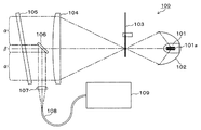
図1には、分光計測装置100が示されている。分光計測装置100は、ハロゲンランプ101、楕円鏡102、光チョッパー103、照射系レンズ104、窓ガラス105、ミラー106、受光系レンズ107、受光ファイバ108および分光器109を備えている。
FIG. 1 shows a
ハロゲンランプ101は、フィラメント101aに通電することにより、波長0.9μm〜2.5μm程度の近赤外光を含む帯域の光を発光する。ここでは、光源としてハロゲンランプを用いる例を示すが、光源としてハロゲンヒータを用いることもできる。ハロゲンヒータは、通電時のフィラメントから生じる輻射熱を用いる目的のものであるが、輻射熱の放射時に波長0.9μm〜2.5μmの近赤外光が得られるので、本発明の光源として用いることができる。
The
楕円鏡102は、ハロゲンランプ101からの光を光チョッパー103の位置(2次光源位置)に集光する。光チョッパー103は、被計測点に向けて照射されるハロゲンランプ101からの光を特定の周波数でチョピングする。光チョッパー103を通すことで、被計測点に照射される照射光が特定の周波数の断続光となる。
The
この例において、光チョッパー103は、1次光源であるハロゲンランプ101に対する2次光源の位置にある。この2次光源である光チョッパー103の位置における光源サイズ(光束径)は、10mm程度のぼやけた点像となる。これは、以下の理由による。まず、フィラメント101aは立体的な形状を有しており、点光源でないため、その発光成分の中には平行光とならない成分も多い。このため、フィラメント101aからの発光を楕円鏡で集光しても一点に集光せず、2次光源位置でぼやけた点像(結果として10mm径程度の点像)となる。
In this example, the
照射系レンズ104は、光チョッパー103でチョッピングされた照射光を被計測点に向けての照射光にビーム成形する。照射系レンズ104の径は、例えばφ=125mm程度のものが採用される。照射系レンズ104は、受光系レンズ107に比較して相対的に長焦点距離の高NAレンズ(相対的に大有効径)である。照射系レンズ104は、その焦点の位置が2〜10m先となるように設定されている。後述するように、分光計測装置100では、光源がフィラメント101aによる発光であることに起因して、照射系光学系の焦点位置精度は厳密でなくてよい。よって、照射系光学系の焦点位置は、想定される最大計測距離に大凡合わせた値とすればよい。もちろん、被計測点との距離に応じて照射系レンズ104の位置を可変できる構造としてもよい。
The
窓ガラス105は、光学系を外部から保護する。窓ガラス105は、ハロゲンランプ101から発生する波長0.9μm〜2.5μm程度の近赤外光に対する透過率が高い材質で構成されている。
The
ミラー106は、被計測点で反射された照射光(以下、検出光)を受光系レンズ107に向けて反射する平面鏡である。ミラー106は、被計測点からの検出光を照射系レンズ104の光軸に対して90°異なる方向に反射する。ミラー106は、照射系レンズ104の光軸中心の位置に配置されており、照射系レンズ104と同軸な位置関係を有している。ミラー106により、被計測点への照射光と同じ光軸上を戻ってきた検出光が当該光軸と90°異なる方向(受光系レンズ107の方向)に反射される。被計測点の方向から見たミラー106の見かけの面積は、照射系レンズ104の1.5%程度に設定されている。
The
なお、ミラー106の光軸は、測定対象点とミラー106の中心を結ぶ第1の光軸と、受光系レンズ107の光軸と一致する第2の光軸とがある。上記の同軸構造というのは、ミラー106に係る上記の第1の光軸と照射系レンズ104の光軸とが同軸関係にあることをいっている。受光系レンズ107は、相対的に短焦点距離の小NA(相対的に有効径小)のレンズであり、ミラー106で反射された検出光を受光ファイバ108に導く。受光系レンズ107の焦点の位置に受光ファイバ108の入射位置がくるように、受光系レンズ107と受光ファイバ108の位置関係が設定されている。
The optical axis of the
受光ファイバ108は、光ファイバであり、そのファイバ径は、例えば0.6mm程度以下のものが用いられている。分光器109は、受光ファイバ108を介して入力される検出光を分光解析し、被計測点の材質に係る情報を得る。分光器109としては、回折格子、プリズム、LVF(リニア・バリアブル・フィルタ)で検出光を分光する形式、光学フィルタで複数の波長帯域を得る形式等が利用できる。また、分光器109で用いる光検出素子として、APD(アバランシェ・フォトダイオード)やラインセンサ等の各種の検出素子を利用することができる。
The
分光器109で行われる処理は、特開2000−14779号公報やその他公知技術として知られている方法を用いて行われる。以下、分光器109で行われる基本的な処理の原理について簡単に説明する。まず、事前に組成や材質の明確な基準試料を用いて特定スペクトルの近赤外光を照射した際の検出光のスペクトル情報を得る。このスペクトル情報はデジタルデータとして分光器109内のメモリに記憶される。計測に当たっては、検出光から得られたスペクトル情報と上記の事前に得たスペクトル情報とを照合し、被計測点の状態についての評価を行う。
The processing performed by the
分光計測装置100では、照射系レンズ104に対して形状の小さいミラー107を用いているが、それは以下の理由による。まず、波長分解能を確保するためには、受光系レンズ107のNAは小さい程よい。これは、受光系レンズ107のNAが大きくなると受光レンズ107で生じる収差の影響が顕在化するからである。他方で受光レンズ107の焦点距離を長くすると、装置が大型化するので、受光レンズ107の焦点距離は短焦点であることが望まれる。また、受光レンズ107のNAが一定の場合、レンズ径を大きくしても受光光量はほとんど増えない。
The
以上のことから、受光レンズ107は、小さく設計することができて、ミラー106の大きさは、受光レンズ107の径に対応するので、結果的にミラー106の面積を小さく設定することになる。
From the above, the
他方で照射系レンズ104は、光源から取り込む光束を増やすため、高NAの相対的に大径であり、また、遠距離での光束径を小さく絞った方が、受光光量が少なくなる遠距離での受光効率を上げることができるため、長焦点のものを採用している。この結果、照射系レンズ104に対してミラー106を小さくし、照射系レンズ104とミラー106を同軸配置とした構造が得られる。この構造では、照射光とミラー106で反射される検出光は光軸が共有され、照射光は照射系レンズ104の光軸の周辺部を通り、ミラー106で反射される検出光は、当該光軸上の中心部を通る。
On the other hand, the
以上述べたように、分光計測装置100は、光源であるハロゲンランプ101と、ハロゲンランプ101からの光を測定対象物に照射する照射光学系を構成する照射系レンズ104と、照射系レンズ104と同軸な位置関係にあり、ハロゲンランプ101と測定対象物の間から検出光を分析部109に導く光学部材であるミラー106と、ミラー106を介して受光する光に基づいて測定対象物を構成する材料を分析する分析部である分光器109とを備え、ミラー106の位置において、ハロゲンランプ101から測定対象物に向かう光は照射系レンズ104の光軸上の周辺部αを通り、分光器109で受光する光は照射系レンズ104の光軸上の中心部βを通る構成を有する。
As described above, the
また、分光計測装置100は、光源であるハロゲンランプ101、光源からの光を集光して2次光源点を形成する楕円鏡102および前記2次光源点からの光を測定対象物に照射するレンズ部材である照射系レンズ104を備える照射光学系と、測定対象物からの光の少なくとも一部を受光し、該受光した光に基づいて前記測定対象物を構成する材料を分析する分析部である分光器109と、照射光学系と同軸の位置に配置され、測定対象物からの光の少なくとも一部を分光器109に導くための反射部材であるミラー106とを備え、ミラー106で反射する測定対象物からの光の光束径が照射系レンズ104を構成する照射光学系から照射する照射光の光束径よりも小さい。
The
(動作)
ハロゲンランプ101からの光は、楕円鏡102で反射され、光チョッパー103の位置で集光する。この光は、光チョッパー103でチョッピングされ、照射系レンズ104で被計測点に集光する光束となり、被計測点に向けて照射される。被計測点からの反射光は、ミラー106で反射され、受光系レンズ107を介して検出光として受光ファイバ108に導かれる。受光ファイバ108に導かれた検出光は、分光器109に導かれ、分光器109では、検出光が分光解析され、被計測点の組成や材質の解析および評価が行われる。この解析および評価により、例えばコンクリート壁面の劣化の状態が診断される。
(Operation)
Light from the
例えば、コンクリートが組成の変質や脆くなる等の材質の変化で劣化した際、この変化を検出光のスペクトル情報を調べることで知ることができる。 For example, when concrete deteriorates due to material changes such as compositional change or brittleness, this change can be known by examining spectral information of detection light.
(優位性)
上述したように、フィラメント101aからの発光に起因して、照射系レンズ104の焦点の位置における照射光は、ある程度の大きさを有するぼやけた点像となる。この傾向は、照射系レンズ104の焦点の位置の前後においても見られる。すなわち、照射光の焦点は、照射系レンズ104の焦点の位置で明確な点像とならないが、光軸上の前後においても像の状態は大きく変化しない。言い換えると、照射光の焦点が明確でなく、光軸上のある程度の範囲において照射光のシャープでない結像が生じる。
(Superiority)
As described above, due to light emission from the
このため、照射系レンズ104の焦点位置の設定は、大凡で良く、被計測点までの距離が多少変化しても受光光量がほとんど変化しないため計測への影響は小さい。よって、固定焦点であっても実用上問題なく分光計測を行うことができる。この固定焦点で良いことは、光学系を簡素化できる優位性にもつながる。
For this reason, the setting of the focal position of the
また、ミラー106を照射系レンズ104と同軸配置することで、光学系の構造の簡素化および小型化を実現しているが、照射系レンズ104を相対的に大口径とし、受光系レンズ107を相対的に小口径とすることで、ミラー107も小さくでき、ミラー107での照射光のケラレを抑えることができる。ここで、「ケラレ」というのは、照射系レンズ104から被計測点に向けて照射される光がミラー107で邪魔され、被計測点からの反射光の検出に支障が出る現象のこという。
Further, by arranging the
上述したように、本実施形態では、フィラメント101aからの発光に平行光とならない成分が多く含まれるため、照射系レンズ104の側から見て、平行光においてミラー106の影となる部分からの反射光も得られ、被計測点までの距離が数10cmと近くても上記のケラレの影響が出難い。
As described above, in the present embodiment, the light emitted from the
図1に示す光学系は、高い波長分解能が得られる上に、部品点数が少なく簡素が構成であり、更に小型化できる優位性がある。 The optical system shown in FIG. 1 has high wavelength resolution, has a small number of parts, is simple in structure, and has an advantage of further miniaturization.
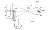
(他の例)
図2には、図1とは異なる光学系の構成を有する分光計測装置200が示されている。分光計測装置200は、ミラー106を照射系レンズ104の光源側に配置し、図1の窓ガラス105を省いた構成を有している。その他の構成は、図1の分光計測装置100と同じである。
(Other examples)
FIG. 2 shows a
図3には、光源であるハロゲンランプ101、ハロゲンランプ101からの光を集光して2次光源点を形成する楕円鏡102、2次光源点からの光を照射光としてビーム成形するレンズ部材である照射系レンズ104および照射系レンズ104からの照射光を測定対象物に向けて反射する反射部材であるミラー301を備える照射光学系と、測定対象物からの光の少なくとも一部を受光し、該受光した光に基づいて前記測定対象物を構成する材料を分析する分析部である分光器109とを備え、ミラー301の中心部は、測定対象物からの光の全部または一部が通過する構造を有し、ミラー301の中心部を通過した測定対象物からの光が分光器109で受光される構造の分光計測装置300が示されている。
FIG. 3 shows a
分光計測装置300では、光源であるハロゲンランプ101からの照射光は、照射系レンズ104を通って、ミラー301で反射され、測定対象物に向かって照射される。ミラー301は、γで示される中央の部分を検出光(検出対象となる近赤外光)が通過するように、γで示される部分が近赤外光を透過する材質で構成された構造、あるいはγで示される部分に孔が開いている構造を有している。測定対象物からの反射光は、γで示される中央の部分を通り、受光系レンズ107に至る。
In the
照射系の光学系と受光系の光学系の同軸構造は、完全な同軸構造でなく、両者の軸が多少ずれていても構わない。利用する波長は、0.9μm以下や2.5μm以上であってもよい。また、光源に関しては、比較的大きな発光面積を有する光源であれば、フィラメントを用いた光源でなくても本発明で利用可能である。計測の対象は、コンクリートに限定されず、木材、植物、食品、セラミックス、金属、各種の建材等であってもよい。 The coaxial structure of the optical system of the irradiation system and the optical system of the light receiving system is not a complete coaxial structure, and the axes of both may be slightly shifted. The wavelength used may be 0.9 μm or less or 2.5 μm or more. As for the light source, any light source having a relatively large light emitting area can be used in the present invention even if it is not a light source using a filament. The object of measurement is not limited to concrete, and may be wood, plants, food, ceramics, metals, various building materials, and the like.
100…分光計測装置、101…ハロゲンランプ(またはハロゲンヒータ)、101a…フィラメント、102…楕円鏡、103…光チョッパー、104…照射系レンズ、105…窓ガラス、106…ミラー、107…受光系レンズ、108…光ファイバ、109…分光器、200…分光計測装置、300…分光計測装置、301…ミラー。
DESCRIPTION OF
Claims (5)
前記光源からの光を測定対象物に照射する照射光学系と、
前記照射光学系と同軸であって、前記光源と前記測定対象物の間から受光部に光を導く光学部材と、
前記光学部材を介して受光する受光部を有し、該受光部が受光した光に基づいて前記測定対象物を構成する材料を分析する分析部と
を備え、
前記光学部材の位置において、
前記光源から前記測定対象物に向かう光は光軸上の周辺部を通り、
前記受光する光は光軸上の中心部を通ることを特徴とする光学分析装置。 A light source;
An irradiation optical system for irradiating the measurement object with light from the light source;
An optical member that is coaxial with the irradiation optical system and guides light from between the light source and the measurement object to a light receiving unit;
A light receiving unit that receives light through the optical member, and an analysis unit that analyzes a material constituting the measurement object based on light received by the light receiving unit,
In the position of the optical member,
The light traveling from the light source toward the measurement object passes through the peripheral portion on the optical axis,
An optical analyzer characterized in that the received light passes through a central portion on an optical axis.
前記測定対象物からの光の少なくとも一部を受光し、該受光した光に基づいて前記測定対象物を構成する材料を分析する分析部と、
前記照射光学系と同軸の位置に配置され、前記測定対象物からの光の少なくとも一部を前記分析部に導くための反射部材と
を備え、
前記反射部材で反射する前記測定対象物からの光の光束径が前記照射光学系から照射する照射光の光束径よりも小さいことを特徴とする光学分析装置。 An illumination optical system comprising a light source, an elliptical mirror for condensing light from the light source to form a secondary light source point, and a lens member for irradiating the measurement object with light from the secondary light source point;
An analysis unit that receives at least a part of light from the measurement object and analyzes a material constituting the measurement object based on the received light;
A reflective member disposed at a position coaxial with the irradiation optical system, and for guiding at least part of light from the measurement object to the analysis unit;
An optical analyzer characterized in that a light beam diameter of light from the measurement object reflected by the reflecting member is smaller than a light beam diameter of irradiation light irradiated from the irradiation optical system.
前記測定対象物からの光の少なくとも一部を受光し、該受光した光に基づいて前記測定対象物を構成する材料を分析する分析部と
を備え、
前記反射部材の中心部は、前記測定対象物からの光が通過する構造を有し、
前記反射部材の中心部を通過した前記測定対象物からの光が前記分析部で受光されることを特徴とする光学分析装置。 A light source, an elliptical mirror that collects light from the light source to form a secondary light source point, a lens member that forms a beam using light from the secondary light source point as irradiation light, and measures the irradiation light from the lens member An irradiation optical system including a reflecting member that reflects toward the object;
An analysis unit that receives at least part of the light from the measurement object, and analyzes a material constituting the measurement object based on the received light;
The central part of the reflecting member has a structure through which light from the measurement object passes,
The optical analysis apparatus, wherein light from the measurement object that has passed through a central portion of the reflection member is received by the analysis unit.
Priority Applications (3)
| Application Number | Priority Date | Filing Date | Title |
|---|---|---|---|
| JP2015010131A JP2016133473A (en) | 2015-01-22 | 2015-01-22 | Optical analysis device |
| US15/545,387 US10557791B2 (en) | 2015-01-22 | 2016-01-19 | Optical Analyzer |
| PCT/JP2016/051366 WO2016117530A1 (en) | 2015-01-22 | 2016-01-19 | Optical analyzer |
Applications Claiming Priority (1)
| Application Number | Priority Date | Filing Date | Title |
|---|---|---|---|
| JP2015010131A JP2016133473A (en) | 2015-01-22 | 2015-01-22 | Optical analysis device |
Publications (2)
| Publication Number | Publication Date |
|---|---|
| JP2016133473A true JP2016133473A (en) | 2016-07-25 |
| JP2016133473A5 JP2016133473A5 (en) | 2018-01-25 |
Family
ID=56417072
Family Applications (1)
| Application Number | Title | Priority Date | Filing Date |
|---|---|---|---|
| JP2015010131A Pending JP2016133473A (en) | 2015-01-22 | 2015-01-22 | Optical analysis device |
Country Status (3)
| Country | Link |
|---|---|
| US (1) | US10557791B2 (en) |
| JP (1) | JP2016133473A (en) |
| WO (1) | WO2016117530A1 (en) |
Citations (7)
| Publication number | Priority date | Publication date | Assignee | Title |
|---|---|---|---|---|
| JPS61102505A (en) * | 1984-10-26 | 1986-05-21 | Hitachi Ltd | Lighting device |
| JPH0261540A (en) * | 1988-08-29 | 1990-03-01 | Nikon Corp | Defect inspector |
| JPH04299207A (en) * | 1991-03-28 | 1992-10-22 | Mitsubishi Rayon Co Ltd | Apparatus for evaluating surface characteristic |
| JP2000111832A (en) * | 1998-08-07 | 2000-04-21 | Sysmex Corp | Multiple light source unit and optical system using the unit |
| JP2001099711A (en) * | 1999-09-30 | 2001-04-13 | Minolta Co Ltd | Test chart colorimetry system and color output instrument calibration system |
| JP2008014779A (en) * | 2006-07-05 | 2008-01-24 | Ihi Corp | Diagnosis method of concrete |
| JP2014149286A (en) * | 2013-01-31 | 2014-08-21 | Nireco Corp | Surface roughness measurement device |
Family Cites Families (14)
| Publication number | Priority date | Publication date | Assignee | Title |
|---|---|---|---|---|
| JPH09210906A (en) * | 1996-02-01 | 1997-08-15 | Bunshi Bio Photonics Kenkyusho:Kk | Proximity field microscope |
| JPH09250982A (en) * | 1996-03-15 | 1997-09-22 | Japan Tobacco Inc | Infrared moisture measuring apparatus |
| JPH1144578A (en) * | 1997-07-24 | 1999-02-16 | Fuji Xerox Co Ltd | Method and device for optical measurement and equipment for forming image |
| US6219476B1 (en) | 1998-08-07 | 2001-04-17 | Sysmex Corporation | Multiple light source unit and optical system using the same |
| JP2000258351A (en) * | 1999-03-08 | 2000-09-22 | Idemitsu Petrochem Co Ltd | Visual examination apparatus and method |
| FR2860869B1 (en) * | 2003-10-10 | 2007-04-20 | Optis | PORTABLE DEVICE FOR MEASURING THE LIGHT INTENSITY OF AN OBJECT AND USE OF SUCH A DEVICE |
| WO2007041458A2 (en) * | 2005-10-03 | 2007-04-12 | The Salk Institute For Biological Studies | Maximal-aperture reflecting objective |
| JP2008215879A (en) * | 2007-02-28 | 2008-09-18 | Toyota Motor Corp | Cleanness judging device and method |
| WO2012147488A1 (en) * | 2011-04-28 | 2012-11-01 | コニカミノルタオプティクス株式会社 | Multi-angle colorimeter |
| US8873596B2 (en) * | 2011-07-22 | 2014-10-28 | Kla-Tencor Corporation | Laser with high quality, stable output beam, and long life high conversion efficiency non-linear crystal |
| US9200887B2 (en) * | 2012-10-12 | 2015-12-01 | Thorlabs, Inc. | Compact, low dispersion, and low aberration adaptive optics scanning system |
| WO2014118935A1 (en) | 2013-01-31 | 2014-08-07 | 株式会社ニレコ | Surface roughness measuring device and surface roughness measuring method |
| US9182278B2 (en) * | 2013-03-14 | 2015-11-10 | Sciaps, Inc. | Wide spectral range spectrometer |
| WO2015118481A1 (en) * | 2014-02-10 | 2015-08-13 | Victoria Link Ltd | Transient grating time resolved luminescence measurements |
-
2015
- 2015-01-22 JP JP2015010131A patent/JP2016133473A/en active Pending
-
2016
- 2016-01-19 US US15/545,387 patent/US10557791B2/en active Active
- 2016-01-19 WO PCT/JP2016/051366 patent/WO2016117530A1/en active Application Filing
Patent Citations (7)
| Publication number | Priority date | Publication date | Assignee | Title |
|---|---|---|---|---|
| JPS61102505A (en) * | 1984-10-26 | 1986-05-21 | Hitachi Ltd | Lighting device |
| JPH0261540A (en) * | 1988-08-29 | 1990-03-01 | Nikon Corp | Defect inspector |
| JPH04299207A (en) * | 1991-03-28 | 1992-10-22 | Mitsubishi Rayon Co Ltd | Apparatus for evaluating surface characteristic |
| JP2000111832A (en) * | 1998-08-07 | 2000-04-21 | Sysmex Corp | Multiple light source unit and optical system using the unit |
| JP2001099711A (en) * | 1999-09-30 | 2001-04-13 | Minolta Co Ltd | Test chart colorimetry system and color output instrument calibration system |
| JP2008014779A (en) * | 2006-07-05 | 2008-01-24 | Ihi Corp | Diagnosis method of concrete |
| JP2014149286A (en) * | 2013-01-31 | 2014-08-21 | Nireco Corp | Surface roughness measurement device |
Also Published As
| Publication number | Publication date |
|---|---|
| WO2016117530A1 (en) | 2016-07-28 |
| US10557791B2 (en) | 2020-02-11 |
| US20180003628A1 (en) | 2018-01-04 |
Similar Documents
| Publication | Publication Date | Title |
|---|---|---|
| US11162843B2 (en) | Spectrometer device and system | |
| US20200370958A1 (en) | Spectrometer device and system | |
| US20210190585A1 (en) | Spectrometer device and system | |
| JP5695302B2 (en) | Combined multipass cell and gas meter | |
| JP5016855B2 (en) | Spectrometer and spectroscopic method | |
| JP6380662B2 (en) | Fourier transform spectrophotometer | |
| US10295408B2 (en) | Raman spectroscopy system | |
| US9874474B2 (en) | Biometric sensor and biometric analysis system including the same | |
| JP2007139632A (en) | Reflectivity measuring instrument and reflectivity measuring method | |
| US20140152841A1 (en) | Method and system for emissivity determination | |
| JP2006058224A (en) | Measuring instrument | |
| CN108955889A (en) | Detector for low-temperature transmission thermometric | |
| RU2448340C1 (en) | Method for optical detection of fluorescence and scattering signals of aerosol particles in stream and optical system for realising said method | |
| KR20150116999A (en) | Micro Raman and photo-luminescence spectral analysis apparatus for multi-channel excitation laser source switching | |
| US10578485B2 (en) | Spectroscopic instrument | |
| WO2016117530A1 (en) | Optical analyzer | |
| US20210298604A1 (en) | Method and apparatus for measuring spectrum of raman-scattered light using time gated detection | |
| JP2021051074A (en) | Spectroscopic analyzer | |
| US10082456B2 (en) | Photothermal conversion spectroscopic analyzer | |
| CN108007570A (en) | Spectrometer and spectral detection system | |
| US9658154B2 (en) | Spectrometer and gas analyzer | |
| JP3830483B2 (en) | Optical configuration for reflection spectroscopy observation. | |
| JP7194580B2 (en) | spectrometer | |
| WO2022168374A1 (en) | Emission optical system, emission device, and optical measurement device | |
| US20150015878A1 (en) | Raman spectroscopic analyzing apparatus |
Legal Events
| Date | Code | Title | Description |
|---|---|---|---|
| A521 | Request for written amendment filed |
Free format text: JAPANESE INTERMEDIATE CODE: A523 Effective date: 20171208 |
|
| A621 | Written request for application examination |
Free format text: JAPANESE INTERMEDIATE CODE: A621 Effective date: 20171208 |
|
| A131 | Notification of reasons for refusal |
Free format text: JAPANESE INTERMEDIATE CODE: A131 Effective date: 20180904 |
|
| A521 | Request for written amendment filed |
Free format text: JAPANESE INTERMEDIATE CODE: A523 Effective date: 20181031 |
|
| A131 | Notification of reasons for refusal |
Free format text: JAPANESE INTERMEDIATE CODE: A131 Effective date: 20190107 |
|
| A521 | Request for written amendment filed |
Free format text: JAPANESE INTERMEDIATE CODE: A523 Effective date: 20190306 |
|
| A02 | Decision of refusal |
Free format text: JAPANESE INTERMEDIATE CODE: A02 Effective date: 20190701 |