JP2016132406A - Underwater sailing body lifting-storage system - Google Patents
Underwater sailing body lifting-storage system Download PDFInfo
- Publication number
- JP2016132406A JP2016132406A JP2015009430A JP2015009430A JP2016132406A JP 2016132406 A JP2016132406 A JP 2016132406A JP 2015009430 A JP2015009430 A JP 2015009430A JP 2015009430 A JP2015009430 A JP 2015009430A JP 2016132406 A JP2016132406 A JP 2016132406A
- Authority
- JP
- Japan
- Prior art keywords
- underwater vehicle
- guide
- underwater
- capture device
- predetermined position
- Prior art date
- Legal status (The legal status is an assumption and is not a legal conclusion. Google has not performed a legal analysis and makes no representation as to the accuracy of the status listed.)
- Pending
Links
Images


Landscapes
- Control Of Position, Course, Altitude, Or Attitude Of Moving Bodies (AREA)
Abstract
Description
本開示は、水中航走体揚収システムに関する。 The present disclosure relates to an underwater vehicle collection system.
従来、例えば海底地形の測量や海洋資源の調査等の目的で、水中を航走する水中航走体が開発されている。水中航走体は、エネルギー補給やデータ交換、あるいは任務完了に伴う母船への帰還等を目的として、母船への揚収が必要になる場合がある。 2. Description of the Related Art Conventionally, an underwater vehicle that travels underwater has been developed for the purpose of, for example, surveying the seabed topography or surveying marine resources. Underwater vehicles may need to be repatriated to the mother ship for the purpose of supplying energy, exchanging data, or returning to the mother ship upon completion of the mission.
特許文献1には、水中航走体を母船へ迅速に揚収するために、マニピュレータを有する遠隔操縦ビークルを海中に投入して水中航走体を捕獲し、母船へ揚収する水中航走体揚収システムが開示されている。 Patent Document 1 discloses an underwater vehicle that inputs a remote control vehicle having a manipulator into the sea, captures the underwater vehicle, and collects it in the mother vessel in order to quickly collect the underwater vehicle to the mother ship. A harvesting system is disclosed.
また、特許文献2には、水中航走体を母船へ揚収する装置ではないが、水中航走体におけるエネルギー補給やデータ交換等を、母船からの支援を要することなく水中で行うことを目的とした水中ドッキング装置が開示されている。この水中ドッキング装置は、水中航走体に設けられた捕捉アームを水中ステーションに設けられたV字状の補足部材に引っ掛けることにより、水中ステーションに水中航走体をドッキングするよう構成されている。
In addition,
特許文献1に記載の水中航走体揚収システムでは、操作員が遠隔操縦ビークルを操縦して水中航走体に接近させ、水中航走体に設けられたリング形状の保持金物をマニピュレータで捕獲する必要があるため、操作員に高い操作精度が要求され、作業負荷も大きくなりやすい。 In the underwater vehicle collection system described in Patent Document 1, an operator operates a remote control vehicle to approach the underwater vehicle and captures a ring-shaped holding hardware provided on the underwater vehicle with a manipulator. Therefore, high operating accuracy is required for the operator, and the work load tends to increase.
また、特許文献2に記載の水中ドッキング装置は、水中航走体の航走海域に比較的大規模な水中ステーションを設置する必要があるため、任意の海域に迅速に展開することが困難である。また、そもそも水中航走体を母船へ揚収する装置ではないため、水中航走体を母船へ迅速に揚収するための知見については開示されていない。
Moreover, since the underwater docking device described in
本発明は、上述したような従来の課題に鑑みなされたものであって、その目的とするところは、操作員の作業負荷を低減し又は操作員を不要とし、水中航走体へ母船を迅速に揚収することを可能とする水中航走体揚収システムを提供することである。 The present invention has been made in view of the above-described conventional problems. The object of the present invention is to reduce the workload of an operator or eliminate the need for an operator, and to quickly move a mother ship to an underwater vehicle. It is an object of the present invention to provide an underwater vehicle lifting system that can be lifted.
(1)本発明の少なくとも一実施形態に係る水中航走体揚収システムは、水中を航走可能な水中航走体を母船に揚収するための水中航走体揚収システムであって、前記水中航走体に接続されたガイド索と、前記水中航走体が水中を航走している状態において前記ガイド索に鉛直方向成分を有する張力を付与可能な浮標又は錘と、前記ガイド索を捕獲するための捕獲装置と、前記捕獲装置を前記母船から吊下するための少なくとも一本の吊下ケーブルと、前記母船に設置され、前記少なくとも一本の吊下ケーブルを巻き上げるための巻き上げ装置と、を備える。 (1) An underwater vehicle collection system according to at least one embodiment of the present invention is an underwater vehicle collection system for collecting an underwater vehicle capable of navigating in water on a mother ship, A guide rope connected to the underwater vehicle, a buoy or weight capable of imparting a tension having a vertical component to the guide rope in a state where the underwater vehicle is underwater, and the guide rope A catching device for catching the catcher, at least one suspension cable for suspending the capture device from the mother ship, and a hoisting device installed on the mother ship for winding up the at least one suspension cable And comprising.
上記(1)に記載の水中航走体揚収システムによれば、鉛直方向成分を有する張力が浮標又は錘によってガイド索に付与され、ガイド索が水中航走体から鉛直上方向又は鉛直下方向に向かって伸びた状態(張った状態)となる。このように水中航走体から鉛直方向に向かって伸びた状態のガイド索を捕獲装置によって捕獲するため、特許文献1に記載されるシステム(マニュピレータでリング形状の保持金物を捕獲するシステム)や特許文献2に記載されるシステム(水中航走体に設けられた捕捉アームに水中ステーションに設けられたV字状の補足部材を引っ掛けるシステム)と比較して、捕獲に要する鉛直方向(深度方向)の位置制御の許容偏差が大きくなり、捕獲装置の深度が所定の値からずれたり波浪等によって時間的に変動する影響を受けにくいため、ドッキングの確実性が増す。さらに、捕獲装置は、母船から吊下ケーブルによって吊下されるため、特許文献2に記載されるような比較的大規模な水中ステーションを水中航走体の航走海域に設置する必要がなく、任意の海域に迅速に展開して水中航走体を捕獲、揚収することができる。
また、水中航走体が自律制御によって捕獲装置とドッキングする方式であり、操作員は捕獲装置をおおよそ一定の速度で曳航して所定の深度と所定の姿勢を保てば済むため、特許文献1のようなマニピュレータ方式と比べ操作員の作業負荷が低減する。
According to the underwater vehicle lifting system described in (1) above, tension having a vertical component is applied to the guide rope by a buoy or weight, and the guide rope is vertically upward or vertically downward from the underwater vehicle. It will be in the state extended toward (a tension state). In order to capture the guide rope extending in the vertical direction from the underwater vehicle in this way, the system described in Patent Document 1 (system for capturing ring-shaped holding hardware with a manipulator) and patent Compared to the system described in Document 2 (a system that hooks a V-shaped supplementary member provided in the underwater station on a capture arm provided in the underwater vehicle), the vertical direction (depth direction) required for capture The tolerance of position control is increased, and the depth of the capture device is not easily affected by a deviation from a predetermined value or temporally fluctuating due to waves or the like, so that the reliability of docking is increased. Furthermore, since the capture device is suspended from the mother ship by a suspension cable, it is not necessary to install a relatively large underwater station as described in
In addition, the underwater vehicle is docked with the capture device by autonomous control, and an operator only has to tow the capture device at an approximately constant speed to maintain a predetermined depth and a predetermined posture. Compared with a manipulator system like this, the operator's workload is reduced.
(2)幾つかの実施形態では、上記(1)に記載の水中航走体揚収システムにおいて、前記浮標又は前記錘を前記水中航走体の表面または内部に固定するための固定機構を更に備え、前記固定機構は、前記浮標又は前記錘を前記水中航走体の前記表面又は前記内部に固定した状態を解除可能に構成される。 (2) In some embodiments, in the underwater vehicle lifting system described in (1) above, a fixing mechanism for fixing the buoy or the weight to the surface or inside of the underwater vehicle is further provided. The fixing mechanism is configured to be able to release a state in which the buoy or the weight is fixed to the surface or the inside of the underwater vehicle.
上記(2)に記載の水中航走体揚収システムによれば、浮標又は錘を水中航走体の表面または内部に固定した状態を解除可能な固定機構を備えることにより、捕獲装置によるガイド索の捕獲時(水中航走体と捕獲装置とのドッキング時)にのみガイド索及び浮標又は錘を海中に放出、展開することが可能となるため、通常の航走時にガイド索及び浮標又は錘が航走の妨げにならないようにすることができる。 According to the underwater vehicle collection system described in (2) above, the guide cable by the capture device is provided by providing a fixing mechanism capable of releasing the state where the buoy or weight is fixed to the surface or inside of the underwater vehicle. Since the guide rope and buoy or weight can be released and deployed into the sea only when catching (when the underwater vehicle and the capture device are docked), the guide rope and buoy or weight are not It can be made so as not to hinder navigation.
(3)幾つかの実施形態では、上記(1)又は(2)に記載の水中航走体揚収システムにおいて、前記水中航走体が水中を航走している状態において前記ガイド索に鉛直方向成分を有する張力を付与可能な前記浮標を備える。 (3) In some embodiments, in the underwater vehicle collection system described in (1) or (2) above, the underwater vehicle is perpendicular to the guide rope in a state where the underwater vehicle is traveling underwater. The buoy can be provided with a tension having a directional component.
上記(3)に記載の水中航走体揚収システムによれば、鉛直方向成分を有する張力が浮標によってガイド索に付与され、ガイド索が水中航走体から鉛直上方向に向かって伸びた状態(張った状態)となる。このように水中航走体から鉛直上方向に向かって伸びた状態のガイド索を捕獲装置によって捕獲するため、捕獲に要する鉛直方向(深度方向)の位置制御の許容偏差を大きくすることができ、捕獲装置の操作員を不要とする又は捕獲装置の操作員の作業負荷を低減することができる。また、捕獲装置は、母船から吊下ケーブルによって吊下されるため、特許文献2に記載されるような比較的大規模な水中ステーションを水中航走体の航走海域に設置する必要がなく、任意の海域に迅速に展開して水中航走体を捕獲、揚収することができる。また、ガイド索が水中航走体から鉛直上方向に向かって伸びた状態となるため、水中航走体が捕獲装置の下方を通ることができ、水中航走体と捕獲装置との干渉を抑制することができる。
According to the underwater vehicle recovery system described in (3) above, a tension having a vertical component is applied to the guide rope by the buoy, and the guide rope extends vertically upward from the underwater vehicle. (Tensioned state). In this way, to capture the guide rope in a state extending vertically upward from the underwater vehicle, the tolerance for position control in the vertical direction (depth direction) required for capture can be increased. The operator of the capture device can be dispensed with or the workload of the operator of the capture device can be reduced. In addition, since the capture device is suspended from the mother ship by a suspension cable, it is not necessary to install a relatively large underwater station as described in
(4)幾つかの実施形態では、上記(1)又は(2)に記載の水中航走体揚収システムにおいて、前記水中航走体が水中を航走している状態において前記ガイド索に鉛直方向成分を有する張力を付与可能な前記錘を備える。 (4) In some embodiments, in the underwater vehicle collection system according to (1) or (2) above, the underwater vehicle is perpendicular to the guide rope in a state of traveling underwater. The weight capable of applying a tension having a directional component is provided.
上記(4)に記載の水中航走体揚収システムによれば、鉛直方向成分を有する張力が錘によってガイド索に付与され、ガイド索が水中航走体から鉛直下方向に向かって伸びた状態(張った状態)となる。このように、水中航走体から鉛直下方向に向かって伸びた状態のガイド索を捕獲装置によって捕獲するため、上述のように、捕獲に要する鉛直方向(深度方向)の位置制御の許容偏差が大きくなり、捕獲装置の操作員を不要とする又は捕獲装置の操作員の作業負荷を低減することができる。また、捕獲装置は、母船から吊下ケーブルによって吊下されるため、特許文献2に記載されるような比較的大規模な水中ステーションを水中航走体の航走海域に設置する必要がなく、任意の海域に迅速に展開して水中航走体を捕獲、揚収することができる。
According to the underwater vehicle recovery system described in (4) above, a tension having a vertical component is applied to the guide cable by the weight, and the guide cable extends vertically downward from the underwater vehicle. (Tensioned state). As described above, since the guide rope extending in the vertically downward direction from the underwater vehicle is captured by the capture device, as described above, there is an allowable deviation in position control in the vertical direction (depth direction) required for capture. It becomes large and the operator of a capture device becomes unnecessary, or the workload of the operator of a capture device can be reduced. In addition, since the capture device is suspended from the mother ship by a suspension cable, it is not necessary to install a relatively large underwater station as described in
なお、水中航走体の浮力は、故障等で動力喪失するなどの緊急時でも海面に自然に浮上するように、中性浮力よりやや正浮力側に設計されるのが一般的である。上記(3)に記載される浮標式の場合において万が一ガイド索が切断したときには、浮標が有していた浮力分が完全に喪失して水中航走体の浮力が負浮力となる恐れがあるが、上記(4)に記載される錘式の場合において万が一ガイド索が切断しても、水中航走体の浮力は正浮力を維持できるというメリットがある。 In general, the buoyancy of the underwater vehicle is designed to be slightly on the positive buoyancy side of the neutral buoyancy so that the buoyancy of the underwater vehicle naturally floats on the sea surface even in case of an emergency such as loss of power. In the case of the buoy type described in (3) above, if the guide cable is cut, the buoyancy component of the buoy may be completely lost and the buoyancy of the underwater vehicle may become negative buoyancy. In the case of the weight type described in the above (4), even if the guide cable is cut, there is an advantage that the buoyancy of the underwater vehicle can maintain the positive buoyancy.
(5)幾つかの実施形態では、上記(4)に記載の水中航走体揚収システムにおいて、前記少なくとも一本の吊下ケーブルは、前記水中航走体と干渉しないように互いに間隔を空けてそれぞれ延在する第1吊下ケーブル及び第2吊下ケーブルを含む。 (5) In some embodiments, in the underwater vehicle landing system according to (4), the at least one suspension cable is spaced from each other so as not to interfere with the underwater vehicle. Each including a first suspension cable and a second suspension cable.
上記(4)に記載のように錘によってガイド索に張力を付与する場合、ガイド索が水中航走体から鉛直下方向に向かって伸びた状態となるため、吊下ケーブルが水中航走体と干渉しないような工夫が必要となる。この点、上記(5)に記載の水中航走体揚収システムでは、水中航走体と干渉しないように互いに間隔を空けてそれぞれ延在する第1吊下ケーブル及び第2吊下ケーブルを上記少なくとも一本の吊下ケーブルが含むため、吊下ケーブルと水中航走体との干渉を容易に回避することができる。 When tension is applied to the guide cable by the weight as described in (4) above, the guide cable extends vertically downward from the underwater vehicle so that the suspended cable is connected to the underwater vehicle. A device that does not interfere is required. In this regard, in the underwater vehicle collection system described in (5) above, the first suspension cable and the second suspension cable that extend at an interval from each other so as not to interfere with the underwater vehicle are described above. Since at least one suspension cable is included, interference between the suspension cable and the underwater vehicle can be easily avoided.
(6)幾つかの実施形態では、上記(1)乃至(5)の何れか1項に記載の水中航走体揚収システムにおいて、前記捕獲装置は、該捕獲装置の姿勢を安定させるための少なくとも一つの安定翼を含む。 (6) In some embodiments, in the underwater vehicle lifting system according to any one of (1) to (5), the capture device is for stabilizing the posture of the capture device. Including at least one stabilizer wing.
上記(6)に記載の水中航走体揚収システムによれば、安定翼によって捕獲装置の姿勢を安定させることにより、鉛直方向に延びた状態のガイド索を捕獲装置によって捕獲しやすくなる。 According to the underwater vehicle recovery system described in (6) above, by stabilizing the posture of the capture device by the stabilizing wings, it becomes easier to capture the guide rope extending in the vertical direction by the capture device.
(7)幾つかの実施形態では、上記(1)乃至(6)の何れか1項に記載の水中航走体揚収システムにおいて、前記捕獲装置は、前記ガイド索を所定位置へ案内するための案内機構と、前記案内機構によって案内された前記ガイド索を前記所定位置に保持するための保持機構とを含む。 (7) In some embodiments, in the underwater vehicle lifting system according to any one of (1) to (6), the capture device guides the guide rope to a predetermined position. And a holding mechanism for holding the guide rope guided by the guide mechanism at the predetermined position.
上記(7)に記載の水中航走体揚収システムによれば、水中航走体が案内機構に向かっておおよその航走制御を行えば、ガイド索が案内機構に案内されて保持機構によって保持される所定位置に導かれるため、水中航走体と捕獲装置とのドッキングが容易となる。 According to the underwater vehicle landing system described in (7) above, when the underwater vehicle performs approximate cruise control toward the guide mechanism, the guide rope is guided by the guide mechanism and held by the holding mechanism. Therefore, the underwater vehicle and the capture device can be docked easily.
(8)幾つかの実施形態では、上記(6)又は(7)に記載の水中航走体揚収システムにおいて、前記保持機構は、前記所定位置からの前記ガイド索の抜け出しを防止するための抜け止め部を有し、前記抜け止め部は、前記案内機構側から前記所定位置側への前記ガイド索の侵入方向の力に対する剛性が、前記所定位置側から前記案内機構側への前記ガイド索の抜け出し方向の力に対する剛性より小さい。 (8) In some embodiments, in the underwater vehicle collection system according to (6) or (7), the holding mechanism is configured to prevent the guide rope from slipping out of the predetermined position. A retaining portion having a rigidity against a force in an intrusion direction of the guide rope from the guide mechanism side to the predetermined position side; and the guide rope from the predetermined position side to the guide mechanism side. It is smaller than the rigidity against the force in the exit direction.
上記(8)に記載の水中航走体揚収システムによれば、ガイド索の張力と抜け止め部の剛性のバランスを適切に設定することにより、簡易な構成でガイド索を所定位置に自動的に(操作員による特段の操作を要することなく)保持することができる。 According to the underwater vehicle lifting system described in (8) above, the guide rope is automatically set to a predetermined position with a simple configuration by appropriately setting the balance between the tension of the guide rope and the rigidity of the retaining portion. (Without requiring any special operation by the operator).
(9)幾つかの実施形態では、上記(6)又は(7)に記載の水中航走体揚収システムにおいて、前記保持機構は、
前記所定位置からの前記ガイド索の抜け出しを防止するための抜け止め部と、前記抜け止め部を、前記案内機構に案内された前記ガイド索の前記所定位置への侵入を許容する許容位置と、前記所定位置からの前記ガイド索の抜け出しを禁止する禁止位置とに移動させるためのアクチュエータと、を有する。
(9) In some embodiments, in the underwater vehicle recovery system according to (6) or (7), the holding mechanism includes:
A retaining portion for preventing the guide rope from slipping out from the predetermined position; and an allowable position for allowing the guide rope guided by the guide mechanism to enter the predetermined position. An actuator for moving the guide cable from the predetermined position to a prohibition position for prohibiting the guide rope from slipping out.
上記(9)に記載の水中航走体揚収システムによれば、上記(8)に記載の水中航走体揚収システムと比較すると保持機構の構造は複雑化するが、ガイド索の張力と抜け止め部の剛性のバランスを設定する必要がなく、ガイド索を所定位置により確実に保持することができる。 According to the underwater vehicle lifting system described in (9) above, the structure of the holding mechanism is complicated as compared with the underwater vehicle lifting system described in (8) above. There is no need to set the balance of rigidity of the retaining portion, and the guide rope can be reliably held at a predetermined position.
(10)幾つかの実施形態では、上記(7)乃至(9)の何れか1項に記載の水中航走体揚収システムにおいて、前記捕獲装置は、前記所定位置を撮影するための水中カメラを含む。 (10) In some embodiments, in the underwater vehicle lifting system according to any one of (7) to (9), the capturing device is an underwater camera for photographing the predetermined position. including.
上記(10)に記載の水中航走体揚収システムによれば、ガイド索が保持機構によって所定位置に確実に保持されているか否かを水中カメラの撮影内容から遠隔操作員が把握できるため、確実に保持されていることを確認した上で巻き上げ装置による吊下ケーブルの巻き上げを行うことができる。また、ガイド索が所定位置に到達したことを水中カメラの撮影内容から遠隔操作員が把握できるため、上記(9)に記載の抜け止め部を上記許容位置から上記禁止位置へ移動させるタイミングを遠隔操作員が判断することができる。 According to the underwater vehicle collection system described in (10) above, since the remote operator can grasp from the photographing content of the underwater camera whether or not the guide rope is securely held at the predetermined position by the holding mechanism, The suspension cable can be wound up by the winding device after confirming that it is securely held. Further, since the remote operator can grasp from the photographing content of the underwater camera that the guide rope has reached the predetermined position, the timing for moving the retaining portion described in (9) from the allowable position to the prohibited position is remotely controlled. The operator can judge.
(11)幾つかの実施形態では、上記(7)乃至(10)の何れか1項に記載の水中航走体揚収システムにおいて、前記案内機構は、第1案内部と、前記第1案内部と間隔をあけて配置された第2案内部とを有し、前記第1案内部と前記第2案内部との間隔は、前記所定位置に近づくにつれて小さくなる。 (11) In some embodiments, in the underwater vehicle recovery system according to any one of (7) to (10), the guide mechanism includes a first guide unit and the first guide. And a second guide part arranged at a distance from each other, and a distance between the first guide part and the second guide part decreases as the position approaches the predetermined position.
上記(11)に記載の水中航走体揚収システムによれば、ガイド索は、案内機構の第1案内部又は第2案内部に沿って移動し、所定位置へ到達して保持機構によって保持される。このため、水中航走体が案内機構に向かっておおよその航走制御を行えば、ガイド索が案内機構に案内されて保持機構によって保持される所定位置に導かれるため、水中航走体と捕獲装置とのドッキングが容易となる。 According to the underwater vehicle lifting system described in (11) above, the guide rope moves along the first guide portion or the second guide portion of the guide mechanism, reaches a predetermined position, and is held by the holding mechanism. Is done. For this reason, if the underwater vehicle performs approximate navigation control toward the guide mechanism, the guide rope is guided by the guide mechanism and guided to a predetermined position held by the holding mechanism. Docking with the device is facilitated.
(12)幾つかの実施形態では、上記(7)乃至(11)の何れか1項に記載の水中航走体揚収システムにおいて、前記捕獲装置は、第1構造物と、前記第1構造物に対して間隔を空けて並設された前記第2構造物と、前記第1構造物及び前記第2構造物を連結する第3構造物とを有する構造物組立体を含み、前記第1案内部および前記第2案内部は、それぞれ、前記第1構造物と前記第2構造物の間に配置され、前記所定位置は、前記第1構造物と前記第2構造物の間に存在し、前記第1案内部及び前記第2案内部は、それぞれ、前記所定位置に対して前記第3構造物とは反対側に設けられる。 (12) In some embodiments, in the underwater vehicle lifting system according to any one of (7) to (11), the capture device includes a first structure and the first structure. A structure assembly having the second structure arranged in parallel to the object at a distance; and a third structure for connecting the first structure and the second structure; The guide part and the second guide part are respectively disposed between the first structure and the second structure, and the predetermined position exists between the first structure and the second structure. The first guide part and the second guide part are respectively provided on the opposite side to the third structure with respect to the predetermined position.
上記(12)に記載の水中航走体揚収システムによれば、第1案内部及び第2案内部によるガイド索の所定位置への案内を妨げることなく、水中航走体の揚収に要する捕獲装置の剛性を構造物組立体によって確保することができる。 According to the underwater vehicle landing system described in (12) above, it is necessary to withdraw the underwater vehicle without disturbing the guide guide to the predetermined position by the first guide unit and the second guide unit. The rigidity of the capture device can be ensured by the structure assembly.
(13)幾つかの実施形態では、上記(12)に記載の水中航走体揚収システムにおいて、前記少なくとも一本の吊下ケーブルは、前記所定位置よりも前記第1構造物側で前記構造物組立体に接続される第1吊下ケーブルと、前記所定位置よりも前記第2構造物側で前記構造物組立体に接続される第2吊下ケーブルとを含む。 (13) In some embodiments, in the underwater vehicle lifting system according to (12), the at least one suspension cable is located on the first structure side of the structure from the predetermined position. A first suspension cable connected to the object assembly; and a second suspension cable connected to the structure assembly closer to the second structure than the predetermined position.
上記(13)に記載の水中航走体揚収システムによれば、捕獲装置の姿勢をより安定させることができる。また、ガイド索に鉛直方向の張力を付与するために上記錘を用いる場合には、第1吊下ケーブルと第2吊下ケーブルとの間隔を十分に空けることにより、第1吊下ケーブル及び第2吊下ケーブルと水中航走体との干渉を回避することができる。 According to the underwater vehicle lifting system described in (13) above, the posture of the capture device can be further stabilized. Further, when the weight is used to apply a vertical tension to the guide rope, the first suspension cable and the second suspension cable can be separated by sufficiently separating the first suspension cable and the second suspension cable. 2. Interference between the suspended cable and the underwater vehicle can be avoided.
(14)幾つかの実施形態では、上記(12)又は(13)に記載の水中航走体揚収システムにおいて、前記第1構造物及び前記第2構造物は、前記捕獲装置の姿勢を安定させるための少なくとも一つの安定翼をそれぞれ有する。 (14) In some embodiments, in the underwater vehicle collection system according to (12) or (13), the first structure and the second structure stabilize the posture of the capture device. Each having at least one stabilizing blade.
上記(14)に記載の水中航走体揚収システムによれば、例えば安定翼として垂直翼を有する場合には、捕獲装置が母船に曳航された状態において捕獲装置の進行方位を容易に安定させることができる。また、安定翼として水平翼を有する場合には、捕獲装置に作用する水中重量と所定の船速(曳航速力)における抵抗、揚力、吊下ケーブル張力が釣り合った状態で捕獲装置の深度を安定させることができる。 According to the underwater vehicle collection system described in (14) above, for example, when a vertical wing is used as a stable wing, the traveling direction of the capture device can be easily stabilized in a state where the capture device is towed by the mother ship. be able to. In addition, when a horizontal wing is used as a stable wing, the depth of the capture device is stabilized in a state where the weight in water acting on the capture device, resistance at a predetermined ship speed (towing speed force), lift, and suspension cable tension are balanced. be able to.
(15)幾つかの実施形態では、上記(12)乃至(14)の何れか1項に記載の水中航走体揚収システムにおいて、前記第1構造物及び前記第2構造物は、前記捕獲装置に作用する揚力を調節するためのフラップをそれぞれ有する。 (15) In some embodiments, in the underwater vehicle lifting system according to any one of (12) to (14), the first structure and the second structure are the capture unit. Each has a flap for adjusting the lift acting on the device.
上記(15)に記載の水中航走体揚収システムによれば、捕獲装置の深度を簡易な構成で調節することができる。 According to the underwater vehicle lifting system described in (15) above, the depth of the capture device can be adjusted with a simple configuration.
(16)幾つかの実施形態では、上記(7)乃至(15)の何れか1項に記載の水中航走体揚収システムにおいて、前記水中航走体に設けられたソーナーと、前記水中航走体に設けられ、前記水中航走体の航走制御を行うよう構成された航走制御部と、を更に備え、前記ソーナーは、質問信号を発信しながら前記捕獲装置の相対位置を判定するアクティブ判定モードを実行可能に構成され、前記捕獲装置は前記ソーナーからの前記質問信号を検出した場合に応答信号を発信するよう構成された音響装置を含み、前記ソーナーは、前記アクティブ判定モードにおいて、前記質問信号の発信タイミング及び前記音響装置からの前記応答信号の到来タイミング並びに前記応答信号の到来方位に基づいて、前記捕獲装置の相対位置を判定するよう構成され、前記航走制御部は、前記ソーナーによって判定した前記捕獲装置の相対位置に基づいて、前記ガイド索を前記捕獲装置の前記所定位置へ誘導するように前記水中航走体の航走制御を行うよう構成される。 (16) In some embodiments, in the underwater vehicle landing system according to any one of (7) to (15), a sonar provided in the underwater vehicle, and the underwater vehicle A traveling control unit provided on the traveling body and configured to perform traveling control of the underwater traveling body, and the sonar determines a relative position of the capturing device while transmitting a question signal. An active determination mode is configured to be executable, and the capture device includes an acoustic device configured to emit a response signal when detecting the interrogation signal from the sonar, the sonar in the active determination mode, The relative position of the capture device is determined based on the transmission timing of the interrogation signal, the arrival timing of the response signal from the acoustic device, and the arrival direction of the response signal And the navigation control unit controls the navigation of the underwater vehicle so as to guide the guide rope to the predetermined position of the capture device based on the relative position of the capture device determined by the sonar. Configured to do.
上記(16)に記載の水中航走体揚収システムでは、アクティブ判定モードにてソーナーにより判定した捕獲装置の相対位置に基づいて、ガイド索を上記所定位置へ誘導するように水中航走体の航走制御を行うよう航走制御部が構成されている。このため、特許文献1に記載されるシステム(マニュピレータを遠隔操作して水中航走体におけるリング形状の保持金物を捕獲するシステム)と比較して、捕獲装置の操作員を不要とする又は捕獲装置の遠隔操作員の作業負荷を低減することができる。 In the underwater vehicle acquisition system described in (16) above, based on the relative position of the capture device determined by the sonar in the active determination mode, the underwater vehicle is guided so as to guide the guide rope to the predetermined position. A cruise control unit is configured to perform cruise control. For this reason, compared with the system described in Patent Document 1 (a system for remotely manipulating a manipulator to capture a ring-shaped holding hardware in an underwater vehicle), the operator of the capture device is unnecessary or the capture device. The workload of remote operators can be reduced.
(17)幾つかの実施形態では、上記(16)に記載の水中航走体揚収システムにおいて、前記音響装置によって発信される前記応答信号の周波数帯は、前記ソーナーによって発信される前記質問信号の周波数帯と異なる。 (17) In some embodiments, in the underwater vehicle acquisition system according to (16), the frequency band of the response signal transmitted by the acoustic device is the question signal transmitted by the sonar. Different from the frequency band.
アクティブ判定モードの実行中には、ソーナーの送信音(質問信号)が海面やその他の周囲構造物(母船の船体等)で後方散乱した音波も該ソーナーに受信されるため、音響装置の送信音(応答信号)をソーナーによって検出する際に後方散乱波が障害になりやすい。 While the active judgment mode is being executed, the sonar transmission sound (question signal) backscattered by the sea surface and other surrounding structures (such as the hull of the mother ship) is also received by the sonar, so the transmission sound of the acoustic device When the (response signal) is detected by a sonar, the backscattered wave tends to be an obstacle.
そこで、上記(17)に記載の水中航走体揚収システムでは、音響装置によって発信される応答信号の周波数帯をソーナーによって発信される質問信号の周波数帯と異ならせている。これにより、上記後方散乱波が障害となるリスクが低減される。 Therefore, in the underwater vehicle lifting system described in (17) above, the frequency band of the response signal transmitted by the acoustic device is different from the frequency band of the interrogation signal transmitted by the sonar. Thereby, the risk that the backscattered wave becomes an obstacle is reduced.
(18)幾つかの実施形態では、上記(16)又は(17)に記載の水中航走体揚収システムにおいて、前記母船に設けられ前記水中航走体の相対距離を計測可能な水中音響測位装置を更に備え、前記水中音響測位装置は、前記相対距離を示す情報を前記音響装置に送信するよう構成され、前記音響装置は、前記水中音響測位装置から送信された前記相対距離を示す情報における前記相対距離が前記基準距離以上である場合に、前記相対距離に対応する時間間隔でピンガー信号を発信するよう構成され、前記ソーナーは、前記ピンガー信号の前記時間間隔に対応する前記相対距離が前記基準距離以上である場合に、前記ピンガー信号の時間間隔及び前記ピンガー信号の到来方位に基づいて前記捕獲装置の相対位置を判定するパッシブ判定モードを実行するよう構成され、前記ソーナーは、前記ピンガー信号の前記時間間隔に対応する前記相対距離が前記基準距離を下回った場合に、前記パッシブ判定モードに替えて前記アクティブ判定モードを実行するよう構成される。 (18) In some embodiments, an underwater acoustic positioning system provided in the mother ship and capable of measuring a relative distance of the underwater vehicle in the underwater vehicle collection system according to (16) or (17). The underwater acoustic positioning device is configured to transmit information indicating the relative distance to the acoustic device, and the acoustic device is in the information indicating the relative distance transmitted from the underwater acoustic positioning device. When the relative distance is equal to or greater than the reference distance, the pinger signal is transmitted at a time interval corresponding to the relative distance, and the sonar is configured so that the relative distance corresponding to the time interval of the pinger signal is A passive determination mode for determining the relative position of the capture device based on the time interval of the Pinger signal and the arrival direction of the Pinger signal when the distance is equal to or greater than a reference distance. The sonar is configured to execute the active determination mode instead of the passive determination mode when the relative distance corresponding to the time interval of the Pinger signal is less than the reference distance. Is done.
アクティブ判定モードの実行中には、音響装置は、母船の船尾付近の高雑音環境下でソーナーからの質問信号を検出する必要があるため、仮に、水中航走体と捕獲装置との相対距離が大きい場合(例えば上記相対距離が上記基準距離より大きい場合)にアクティブ判定モードを実行しようとすると、ソーナーによる質問信号の送波レベルを高めるなど設計上の制約条件が厳しくなる。これに対し、パッシブ判定モードでは、音響装置は、一方的にピンガー音を発信するだけで済み、母船の船尾付近の高雑音環境下でソーナーからの質問信号を検出する必要がない。 During the execution of the active judgment mode, the acoustic device needs to detect the interrogation signal from the sonar in a high noise environment near the stern of the mother ship, so it is assumed that the relative distance between the underwater vehicle and the capture device is If the active determination mode is to be executed when the distance is larger (for example, when the relative distance is larger than the reference distance), design constraints such as increasing the transmission level of the question signal by the sonar become stricter. On the other hand, in the passive determination mode, the acoustic device only needs to unilaterally transmit a pinger sound, and does not need to detect a question signal from the sonar in a high noise environment near the stern of the mother ship.
このため、上記(18)に記載のように、水中音響測位装置によって計測した水中航走体の相対距離が基準距離以上の場合にパッシブ判定モードを実行し、該相対距離が基準距離を下回ったらアクティブ判定モードを実行することで、音響装置の仕様及びソーナーの仕様を簡素化することができる。また、母船から遠方に水中航走体があるときの水中航走体の初期誘導と、母船に水中航走体2が接近した際の水中航走体のターミナル誘導とをスムーズに切り替えて実現することができる。
For this reason, as described in (18) above, when the relative distance of the underwater vehicle measured by the underwater acoustic positioning device is equal to or greater than the reference distance, the passive determination mode is executed, and the relative distance falls below the reference distance. By executing the active determination mode, the specifications of the acoustic device and the specifications of the sonar can be simplified. Also, it is possible to smoothly switch between the initial guidance of the underwater vehicle when there is an underwater vehicle far from the mother ship and the terminal guidance of the underwater vehicle when the
本発明の少なくとも一つの実施形態によれば、操作員の作業を低減し又は操作員の作業を要することなく、水中航走体へ母船を迅速に揚収することを可能とする水中航走体揚収システムが提供される。 According to at least one embodiment of the present invention, an underwater vehicle capable of quickly picking up a mother ship to the underwater vehicle without reducing or requiring the operator's work. A pick-up system is provided.
以下、添付図面を参照して本発明の幾つかの実施形態について説明する。ただし、実施形態として記載されている又は図面に示されている構成部品の寸法、材質、形状、その相対的配置等は、本発明の範囲をこれに限定する趣旨ではなく、単なる説明例にすぎない。
例えば、「ある方向に」、「ある方向に沿って」、「平行」、「直交」、「中心」、「同心」或いは「同軸」等の相対的或いは絶対的な配置を表す表現は、厳密にそのような配置を表すのみならず、公差、若しくは、同じ機能が得られる程度の角度や距離をもって相対的に変位している状態も表すものとする。
例えば、「同一」、「等しい」及び「均質」等の物事が等しい状態であることを表す表現は、厳密に等しい状態を表すのみならず、公差、若しくは、同じ機能が得られる程度の差が存在している状態も表すものとする。
例えば、四角形状や円筒形状等の形状を表す表現は、幾何学的に厳密な意味での四角形状や円筒形状等の形状を表すのみならず、同じ効果が得られる範囲で、凹凸部や面取り部等を含む形状も表すものとする。
一方、一の構成要素を「備える」、「具える」、「具備する」、「含む」、又は、「有する」という表現は、他の構成要素の存在を除外する排他的な表現ではない。
Hereinafter, some embodiments of the present invention will be described with reference to the accompanying drawings. However, the dimensions, materials, shapes, relative arrangements, etc. of the components described in the embodiments or shown in the drawings are not intended to limit the scope of the present invention, but are merely illustrative examples. Absent.
For example, expressions expressing relative or absolute arrangements such as “in a certain direction”, “along a certain direction”, “parallel”, “orthogonal”, “center”, “concentric” or “coaxial” are strictly In addition to such an arrangement, it is also possible to represent a state of relative displacement with an angle or a distance such that tolerance or the same function can be obtained.
For example, an expression indicating that things such as “identical”, “equal”, and “homogeneous” are in an equal state not only represents an exactly equal state, but also has a tolerance or a difference that can provide the same function. It also represents the existing state.
For example, expressions representing shapes such as quadrangular shapes and cylindrical shapes represent not only geometrically strict shapes such as quadrangular shapes and cylindrical shapes, but also irregularities and chamfers as long as the same effects can be obtained. A shape including a part or the like is also expressed.
On the other hand, the expressions “comprising”, “comprising”, “comprising”, “including”, or “having” one constituent element are not exclusive expressions for excluding the existence of the other constituent elements.
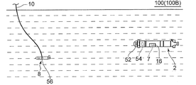
図1は、一実施形態に係る水中航走体揚収システム100(100A)の全体構成を概略的に示す図である。水中航走体揚収システム100(100A)は、水中を航走可能な水中航走体2を母船14に揚収するためのシステムであり、水中航走体2、ガイド索4、浮標6、捕獲装置8、少なくとも一本の吊下ケーブル10、巻き上げ装置12及び母船14を備える。
FIG. 1 is a diagram schematically showing an overall configuration of an underwater vehicle lifting system 100 (100A) according to an embodiment. The underwater vehicle landing system 100 (100A) is a system for collecting the
水中航走体2は、例えば小型の自律型無人潜水機(AUV:Autonomous Underwater Vehicle)である。
The
ガイド索4は水中航走体2に接続されている。ガイド索4の上端には浮標6が取り付けられており、浮標6は、水中航走体2が水中を航走している状態においてガイド索4に鉛直方向成分(深度方向成分)を有する張力を付与可能に構成されている。浮標6は、水中航走体2が捕獲装置8とドッキングするために航走しているときの航走速力において、ガイド索4がおおよそ鉛直方向に張る程度の浮力、揚力及び抗力を有する材質と形状である。
The
捕獲装置8は、少なくとも一本の吊下ケーブル10によって母船14から吊下された状態で、該吊下ケーブル10を介して母船14によって曳航される。捕獲装置8は、母船14によって曳航された状態において、ガイド索4を捕獲することにより水中航走体2を捕獲するよう構成されている。なお、後で詳述するが、水中航走体揚収システム100では、捕獲装置8を水中航走体2へ向けて積極的に移動させて捕獲する方式ではなく、水中航走体2がガイド索4を捕獲装置8へ自律誘導する方式が採用される。
The
巻き上げ装置12は、吊下ケーブル10を巻き上げ可能に構成されており、捕獲装置8による水中航走体2の捕獲が完了した後に、吊下ケーブル10を巻き上げることによって水中航走体2を母船14に揚収する。巻き上げ装置12は、例えばクレーン、ウインチ又はホイストであってもよい。なお、水中航走体2の母船14への揚収は、捕獲装置8によって捕獲したガイド索4を母船14の甲板上まで引き上げることによって行ってもよいし、ガイド索4の強度が不足している場合には、捕獲装置8によって捕獲したガイド索4を水面付近まで引き上げた後、より強度の高い不図示の揚収用引き上げ索を水中航走体2に接続して、該揚収用引き上げ索を用いて母船14の甲板上まで引き上げてもよい。
The hoisting
水中航走体揚収システム100(100A)によれば、鉛直方向成分を有する張力が浮標6によってガイド索4に付与され、ガイド索4が水中航走体2から鉛直上方向に向かって伸びた状態(張った状態)となる。このように、水中航走体2から鉛直上方向に向かって伸びた状態のガイド索4を捕獲装置8によって捕獲するため、特許文献1に記載されるシステム(マニュピレータを遠隔操作して水中航走体におけるリング形状の保持金物を捕獲するシステム)や特許文献2に記載されるシステム(水中航走体に設けられた捕捉アームに水中ステーションに設けられたV字状の補足部材を引っ掛けるシステム)と比較して、捕獲に要する鉛直方向(深度方向)の位置制御の許容偏差が大きくなり、捕獲装置8の深度が所定の値からずれたり波浪等によって時間的に変動する影響を受けにくいため、ドッキングの確実性が増す。さらに、捕獲装置8は、母船14から吊下ケーブル10によって吊下されるため、特許文献2に記載されるような比較的大規模な水中ステーションを水中航走体2の航走海域に設置する必要がなく、任意の海域に迅速に展開して水中航走体2を捕獲、揚収することができる。
According to the underwater vehicle landing system 100 (100A), a tension having a vertical component is applied to the
また、水中航走体2が自律制御によって捕獲装置8とドッキングする方式であり、操作員は捕獲装置8をおおよそ一定の速度で曳航して所定の深度と所定の姿勢を保てば済むため、特許文献1のようなマニピュレータ方式と比べ操作員の作業負荷が低減する。
In addition, the
なお、図1に示す例示的な実施形態では、ガイド索4は分岐しており、分岐位置の下側において水中航走体2に複数箇所で接続している。一実施形態では、ガイド索4は、水中航走体2の長手方向jにおいて重心に対して一方側と他方側とに接続されていてもよい。これにより、水中航走体2の姿勢を安定させた状態で水中航走体を揚収することができる。
In the exemplary embodiment shown in FIG. 1, the
図2A〜図2Cは、捕獲装置8に対する水中航走体2の接近に伴って、図1に示した浮標6が水中航走体2の表面又は内部から海中に放出(水中航走体2の表面から分離)される様子を示す図である。
2A to 2C, as the
一実施形態では、図2A〜図2Cに示されるように、水中航走体揚収システム100(100A)は、浮標6を水中航走体2の表面または内部に固定するための固定機構16を更に備える。図2Aに示すように、水中航走体2が捕獲装置8から比較的離れた位置を航走している通常の航走状態においては、固定機構16は、ガイド索4の全部又は一部と浮標6とを航走の妨げとならないように水中航走体2の表面又は内部に固定するよう構成されている。図2Bに示すように、固定機構16は、水中航走体2が捕獲装置8に接近して捕獲装置8とのドッキングタイミングが近づくと、浮標6を水中航走体2の表面又は内部に固定した状態を解除して浮標6を海中に放出する。これにより、鉛直方向成分を有する張力が浮標6によってガイド索4に付与され、ガイド索4が鉛直上方向に向かって伸びた状態(張った状態)となる。そして、図2Cに示すように、水中航走体2から鉛直上方向に向かって伸びた状態のガイド索4を捕獲装置8によって捕獲する。
In one embodiment, as shown in FIGS. 2A to 2C, the underwater vehicle collection system 100 (100 </ b> A) includes a
このように、浮標を水中航走体の表面または内部に固定した状態を解除可能な固定機構16を備えることにより、捕獲装置8によるガイド索4の捕獲時(水中航走体2と捕獲装置8とのドッキング時)にのみガイド索4や浮標6を海中に放出、展開することが可能となるため、通常の航走時にガイド索4や浮標6が航走の妨げにならないようにすることができる。
In this way, by providing the
図3は、一実施形態に係る水中航走体揚収システム100(100B)の全体構成を概略的に示す図である。水中航走体揚収システム100(100B)が備える構成のうち、図1に示した水中航走体揚収システム100(100A)が備える構成と同様の構成については、同一の符号を付して説明を省略する。図3に示す水中航走体揚収システム100(100B)は、ガイド索4に鉛直方向成分を有する張力を付与するための手段が図1に示す水中航走体揚収システム100(100A)と異なる。すなわち、図1に示す水中航走体揚収システム100(100A)は、ガイド索4に鉛直方向成分を有する張力を付与可能な浮標6を備えているが、図3に示す水中航走体揚収システム100(100B)は、浮標6の代わりに、ガイド索4に鉛直方向成分を有する張力を付与可能な錘7を備えている。
FIG. 3 is a diagram schematically showing an overall configuration of the underwater vehicle lifting system 100 (100B) according to the embodiment. Among the configurations included in the underwater vehicle collection system 100 (100B), the same components as those included in the underwater vehicle collection system 100 (100A) illustrated in FIG. Description is omitted. In the underwater vehicle collection system 100 (100B) shown in FIG. 3, the means for applying a tension having a vertical component to the
水中航走体揚収システム100(100B)によれば、鉛直方向成分(深度方向成分)を有する張力が錘7によってガイド索4に付与され、ガイド索4が水中航走体2から鉛直下方向に向かって伸びた状態(張った状態)となる。そして、水中航走体2から鉛直下方向に向かって伸びた状態のガイド索4を捕獲装置8によって捕獲するため、特許文献1に記載されるシステム(マニュピレータでリング形状の保持金物を捕獲するシステム)や特許文献2に記載されるシステム(水中航走体に設けられた捕捉アームに水中ステーションに設けられたV字状の補足部材を引っ掛けるシステム)と比較して、捕獲に要する鉛直方向の位置制御の許容偏差を大きくすることができ、捕獲装置8の操作員を不要とする又は捕獲装置8の操作員の作業負荷を低減することができる。
According to the underwater vehicle landing system 100 (100B), a tension having a vertical component (depth component) is applied to the
また、捕獲装置8は、母船14から吊下ケーブル10によって吊下されるため、特許文献2に記載されるような比較的大規模な水中ステーションを水中航走体2の航走海域に設置する必要がなく、任意の海域に迅速に展開して水中航走体2を捕獲、揚収することができる。また、水中航走体2には捕獲装置8とのドッキングのためのマニピュレータ等が不要であるため、水中航走体2の装置構成を簡素化し、水中航走体2を小型化することができる。また、水中航走体2と捕獲装置8とのドッキングを海面ではなく海中で行うことができるため、波浪の影響等が軽減され、ドッキングが容易である。
Further, since the
なお、水中航走体揚収システム100(100B)では、ガイド索4が水中航走体2から鉛直下方向に向かって伸びた状態となるため、捕獲装置8又は吊下ケーブル10が水中航走体2と干渉しないような工夫が必要となる。このため、例えば、後で詳述するように、吊下ケーブル10は、水中航走体2と干渉しないように互いに間隔を空けてそれぞれ延在する第1吊下ケーブル及び第2吊下ケーブルを含んでいてもよい。
Note that, in the underwater vehicle body collection system 100 (100B), the
図4A〜図4Cは、捕獲装置8に対する水中航走体2の接近に伴って、図3に示した錘7が水中航走体2の表面又は内部から海中に放出(水中航走体2の表面から分離)される様子を示す図である。
4A to 4C, as the
一実施形態では、図4A〜図4Cに示されるように、水中航走体揚収システム100(100B)は、錘7を水中航走体2の表面または内部に固定するための固定機構16を更に備える。図4Aに示すように、水中航走体2が捕獲装置8から比較的離れた位置を航走している通常の航走状態においては、固定機構16は、ガイド索4の全部又は一部と錘7とを航走の妨げとならないように水中航走体2の表面(底面)又は内部に固定するよう構成されている。図4Bに示すように、固定機構16は、水中航走体2が捕獲装置8に接近して捕獲装置8とのドッキングタイミングが近づくと、錘7を水中航走体2の表面又は内部に固定した状態を解除して錘7を海中に放出する。これにより、鉛直下方向成分を有する張力が錘7によってガイド索4に付与され、ガイド索4が鉛直下方向に向かって伸びた状態(張った状態)となる。そして、図4Cに示すように、水中航走体2から鉛直下方向に向かって伸びた状態のガイド索4を捕獲装置8によって捕獲する。
In one embodiment, as shown in FIGS. 4A to 4C, the underwater vehicle collection system 100 (100B) includes a
このように、錘7を水中航走体の表面または内部に固定した状態を解除可能な固定機構16を備えることにより、捕獲装置8によるガイド索4の捕獲時(水中航走体2と捕獲装置8とのドッキング時)にのみガイド索4や錘7を海中に放出することが可能となるため、通常の航走時にガイド索4や錘7が航走の妨げにならないようにすることができる。
Thus, by providing the
次に、図1〜図4C中の捕獲装置8の具体的構成例について、図5〜図10を用いて幾つかの実施形態を説明する。
図5は、一実施形態に係る捕獲装置8(8A)を模式的に示す上面図である。図6は、図5に示した捕獲装置8(8A)の側面図である。図7は、図5に示した捕獲装置8(8A)の背面図である。図8は、一実施形態に係る捕獲装置8(8B)を模式的に示す上面図である。図9は、図8に示した捕獲装置8(8B)の側面図である。図10は、図8に示した捕獲装置8(8B)の背面図である。なお、捕獲装置8(8A)は、図1〜図2Cに示した水中航走体揚収システム100(100A)における捕獲装置8として採用してもよいし、図3〜図4Cに示した水中航走体揚収システム100(100B)における捕獲装置8として採用しても良い。また、捕獲装置8(8B)は、図1〜図2Cに示した水中航走体揚収システム100(100A)における捕獲装置8として採用してもよいし、図3〜図4Cに示した水中航走体揚収システム100(100B)における捕獲装置8として採用しても良い。
Next, several embodiments of the specific configuration example of the
FIG. 5 is a top view schematically showing the capture device 8 (8A) according to one embodiment. FIG. 6 is a side view of the capturing device 8 (8A) shown in FIG. FIG. 7 is a rear view of the capturing device 8 (8A) shown in FIG. FIG. 8 is a top view schematically showing the capture device 8 (8B) according to one embodiment. FIG. 9 is a side view of the capture device 8 (8B) shown in FIG. FIG. 10 is a rear view of the capturing device 8 (8B) shown in FIG. The capture device 8 (8A) may be adopted as the
幾つかの実施形態では、例えば図5及び図8に示すように、捕獲装置8(8A,8B)は、ガイド索4を所定位置Pへ案内するための案内機構18と、案内機構18によって案内されたガイド索4を所定位置Pに保持する(ラッチする)ための保持機構20(ラッチ機構)とを含む。案内機構18は、第1案内部22と、第1案内部22と間隔をあけて配置された第2案内部24とを有し、第1案内部22と第2案内部24との間隔は、所定位置Pに近づくにつれて小さくなっている。このため、ガイド索4は、案内機構18の第1案内部22又は第2案内部24に沿って移動し、所定位置Pへ到達して保持機構20によって保持される。
In some embodiments, for example, as shown in FIGS. 5 and 8, the capturing device 8 (8 </ b> A, 8 </ b> B) is guided by the
これにより、水中航走体2が案内機構18に向かっておおよその航走制御を行えば、ガイド索4が案内機構18に案内されて保持機構20によって保持される所定位置Pに導かれるため、水中航走体2と捕獲装置8(8A,8B)とのドッキングが容易となる。
Thus, when the
幾つかの実施形態では、例えば図5及び図8に示すように、捕獲装置8(8A,8B)は、第1構造物26と、第1構造物26に対して間隔を空けて並設された第2構造物28と、第1構造物26及び第2構造物28を連結する第3構造物30とを有する構造物組立体32を含む。この場合、上述した第1案内部22および第2案内部24は、それぞれ、第1構造物26と第2構造物28の間に配置される。また、所定位置Pは、第1構造物26と第2構造物28の間に存在し、第1案内部22及び第2案内部24は、それぞれ、所定位置Pに対して第3構造物30とは反対側に設けられる。
In some embodiments, for example, as shown in FIGS. 5 and 8, the capture device 8 (8 </ b> A, 8 </ b> B) is juxtaposed with the
これにより、第1案内部22及び第2案内部24によるガイド索4の所定位置Pへの案内を妨げることなく、水中航走体2の揚収に要する捕獲装置8(8A,8B)の剛性を構造物組立体32によって確保することができる。
Thereby, the rigidity of the capture device 8 (8A, 8B) required for the lifting and lowering of the
なお、図5及び図8に示す幾つかの実施形態では、案内機構18は、第1案内板23及び第2案内板25を含んでいる。第1案内板23及び第2案内板25は、それぞれ、捕獲装置8が母船14に曳航されている状態において鉛直方向を厚さ方向とする板状の部材である。第1案内板23及び第2案内板25は、互いの間に所定位置Pが存在するよう配置されている。第1案内板23は、捕獲装置8の進行方向d1における前方側で第3構造物30に連結しており、進行方向d1に直交する水平方向d2における所定位置Pと反対側で第1構造物26に連結している。第1案内部22は、捕獲装置8の進行方向d1における第1案内板23の後端に設けられている。第2案内板25は、捕獲装置8の進行方向d1における前方側で第3構造物30に連結しており、進行方向d1に直交する水平方向d2における所定位置Pと反対側で第2構造物28に連結している。第2案内部24は、捕獲装置8の進行方向d1における第2案内板25の後端に設けられている。なお、図示した実施形態では、案内機構18の具体的構成として第1案内板23及び第2案内板25を例示したが、板状の部材に限定されず、梁状の部材であってもよい。
In some embodiments shown in FIGS. 5 and 8, the
幾つかの実施形態では、例えば図5及び図8に示すように、吊下ケーブル10は、所定位置Pよりも第1構造物26側で構造物組立体32に接続される第1吊下ケーブル46と、所定位置Pよりも第2構造物28側で構造物組立体32に接続される第2吊下ケーブル48とを含む。これにより、捕獲装置8(8A,8B)の姿勢をより安定させることができる。
In some embodiments, for example, as shown in FIGS. 5 and 8, the
なお、上述した水中航走体揚収システム100(100B)に捕獲装置8(8A,8B)を採用する場合においては、第1吊下ケーブル46及び第2吊下ケーブル48は、水中航走体2と干渉しないような間隔を互いに空けてそれぞれ延在するように、構造物組立体32に接続することが望ましい。これにより、ガイド索4に鉛直方向の張力を付与するための錘を用いる場合であっても、吊下ケーブル10(第1吊下ケーブル46及び第2吊下ケーブル48)と水中航走体2との干渉を回避することができる。
In addition, when employ | adopting capture apparatus 8 (8A, 8B) for the underwater vehicle body collection system 100 (100B) mentioned above, the
また、吊下ケーブル10のうち少なくとも一本(第1吊下ケーブル46及び第2吊下ケーブル48)は、捕獲装置8に設置される電装品(例えば後述する音響装置56)の電源ライン及び信号ラインを兼ねていてもよい。すなわち、吊下ケーブル10のうち少なくとも一本は、電源ライン及び信号ラインのそれ自体から構成されていてもよく、電源ライン及び信号ラインをその一部に含むように構成されていてもよい。
In addition, at least one of the suspension cables 10 (the
一実施形態では、例えば図5〜図7に示すように、第1構造物26及び第2構造物28は、それぞれ、捕獲装置8の進行方向d1に沿った軸線を有する円柱状の構造物である。第3構造物30は、該軸線に直交する水平方向d2に延在する板状の構造物である。板状の第3構造物30の鉛直方向の厚みD3は、第1構造物26と第3構造物との連結位置での第1構造物26の外径E1より小さく、第2構造物28と第3構造物30との接続位置での第2構造物の外径E2より小さい。
In one embodiment, for example, as shown in FIGS. 5 to 7, each of the
一実施形態では、例えば図5〜図7に示すように、第1構造物26及び第2構造物28は、捕獲装置8の姿勢を安定させるための少なくとも一つの安定翼34をそれぞれ有する。安定翼34として垂直翼36(例えば垂直尾翼)を有する場合には、捕獲装置8が母船14に曳航された状態において捕獲装置8の進行方位を容易に安定させることができる。また、安定翼34として水平翼38を有する場合には、捕獲装置8に作用する水中重量と所定の船速(曳航速力)における抵抗、揚力、吊下ケーブル張力が釣り合った状態で捕獲装置8の深度を安定させることができる。図示した実施形態では、水平翼38は、第1構造物26及び第2構造物28の外側(第3構造物30との連結位置と反対側)に設けられている。
In one embodiment, for example, as shown in FIGS. 5 to 7, each of the
一実施形態では、垂直翼36及び水平翼38の少なくとも一方を操舵翼とし、捕獲装置8に設けられた不図示の深度センサ及び姿勢センサの出力に基づいて該操舵翼を制御することにより、適切な深度を維持するための深度制御及び姿勢をより安定化させるためのヨー、ピッチ、ロール姿勢制御を行っても良い。すなわち、垂直翼36及び水平翼38の少なくとも一方の翼角を不図示のアクチュエータによって可変な構成とし、深度センサ及び姿勢センサの出力に基づいてアクチュエータを制御するようにしても良い。これにより、装置構成は複雑化するが、天候不良で海面が荒れて母船14の船体が動揺した場合でも、捕獲装置8の深度が安定し、動揺がある程度抑制されるため、ドッキングの確実性が向上する。
In one embodiment, at least one of the
一実施形態では、例えば図8〜図10に示すように、第1構造物26及び第2構造物28は、それぞれ、捕獲装置8の進行方向d1を長手方向とし、進行方向に直交する水平方向d2を短手方向とし、鉛直方向を厚さ方向とする板状の構造物である。第3構造物30は、該進行方向に直交する水平方向に延在する柱状の構造物である。柱状の第3構造物30の鉛直方向の厚みD3は、板状の第1構造物26の鉛直方向の厚みD1より大きく、板状の第2構造物28の鉛直方向の厚みD2より大きい。
In one embodiment, for example, as shown in FIGS. 8 to 10, each of the
一実施形態では、例えば図8〜図10に示すように、捕獲装置8の進行方向d1における第1構造物26の後端及び第2構造物28の後端には、捕獲装置8に作用する揚力を調節するためのフラップ44が設けられている。図示した実施形態では、フラップ44は、鉛直方向(板状の第1構造物26及び第2構造物28における厚さ方向)に回動可能なように、第1構造物26の後端及び第2構造物28の後端に連結されている。これにより、捕獲装置8の深度を簡易な構成で調節することができる。
In one embodiment, for example, as shown in FIGS. 8 to 10, the rear end of the
図11A〜図11Cは、図5及び図8に示した保持機構20の具体的構成例である保持機構20(20A)を模式的に示す上面図であり、図11Aは、案内機構18によってガイド索4が案内されている様子を示しており、図11Bは、ガイド索4が保持機構20(20A)によって保持される所定位置Pに到達する直前の様子を示しており、図11Cは、ガイド索4が保持機構20(20A)によって所定位置Pに保持されている様子を示している。
11A to 11C are top views schematically showing a holding mechanism 20 (20A), which is a specific configuration example of the
一実施形態では、例えば図11A〜図11Cに示すように、保持機構20(20A)は、所定位置Pからのガイド索4の抜け出しを防止するための抜け止め部21(21A)を有する。ここで、抜け止め部21(21A)は、案内機構18側から所定位置P側へのガイド索4の進入方向Iの力に対する剛性が、所定位置P側から案内機構18側へのガイド索4の抜け出し方向Oの力に対する剛性より小さい。すなわち、抜け止め部21(21A)は、案内機構18側から所定位置P側へのガイド索4の侵入方向Iへ撓みやすく、所定位置P側から案内機構18側へのガイド索4の抜け出し方向Oへ撓み難い。図示した実施形態では、抜け止め部21(21A)は、第1案内板23及び第2案内板25の各々から互いに対向して突出するように設けられた一対の先細り形状部から構成されている。このため、ガイド索4の張力と抜け止め部21(21A)の剛性のバランスを適切に設定することにより、簡易な構成でガイド索4を所定位置Pに自動的に(操作員による特段の操作を要することなく)保持することができる。なお、図11A〜図11Cに示す実施形態では、第3構造物30、第1案内板23、第2案内板25、抜け止め部21(21A)によって保持機構20(20A)が構成される。また、抜け止め部21(21A)は、第1案内板23と第2案内板25にそれぞれ一つずつ設けられている例を示したが、第1案内板23と第2案内板25の何れか一方にのみ設けてもよい。
In one embodiment, for example, as illustrated in FIGS. 11A to 11C, the holding mechanism 20 (20 </ b> A) includes a retaining portion 21 (21 </ b> A) for preventing the
図12A〜図12Cは、図5及び図8に示した保持機構20の具体的構成例である保持機構20(20B)を模式的に示す上面図であり、図12Aは、案内機構18によってガイド索4が案内されている様子を示しており、図12Bは、ガイド索4が保持機構20(20B)によって保持される所定位置Pに到達した様子を示しており、図12Cは、ガイド索4が保持機構20(20B)によって所定位置Pに保持されている様子を示している。
12A to 12C are top views schematically showing a holding mechanism 20 (20B), which is a specific configuration example of the
一実施形態では、例えば図12A〜図12Cに示すように、保持機構20(20B)は、所定位置からのガイド索4の抜け出しを防止するための抜け止め部21(21B)と、アクチュエータ33とを有する。アクチュエータ33は、抜け止め部21(21B)を、案内機構18に案内されたガイド索4の所定位置Pへの侵入を許容する許容位置(図12Aにおける抜け止め部21の位置)と、所定位置Pからのガイド索4の抜け出しを禁止する禁止位置(図12Cにおける抜け止め部21の位置)とに移動させるためのアクチュエータ33と、を有する。図示する実施形態では、抜け止め部21(21B)は、第1案内部材25に設けられており、許容位置から第2案内部材23の方向に移動することで禁止位置に移動する。抜け止め部21(21B)は、禁止位置にあるときに第1案内部材25から第2案内部材25に亘って延在していてもよい。図11A〜図11Cに示す実施形態では、第3構造物30、第1案内板23、第2案内板25、及び抜け止め部21(21B)によって保持機構20(20B)が構成される。
In one embodiment, for example, as shown in FIGS. 12A to 12C, the holding mechanism 20 (20 </ b> B) includes a retaining portion 21 (21 </ b> B) for preventing the
保持機構20(20B)によれば、保持機構20(20A)と比較すると構造は複雑化するが、ガイド索4の張力と抜け止め部21の剛性のバランスを設定する必要がなく、ガイド索4を所定位置Pにより確実に保持することができる。
According to the holding mechanism 20 (20B), the structure is complicated as compared with the holding mechanism 20 (20A), but it is not necessary to set the balance between the tension of the
幾つかの実施形態では、例えば図5、図7、図8及び図10に示すように、捕獲装置8(8A,8B)は、所定位置Pを撮影するための水中カメラ50を含む。
In some embodiments, for example, as shown in FIGS. 5, 7, 8 and 10, the capture device 8 (8 </ b> A, 8 </ b> B) includes an
これにより、ガイド索4が保持機構20(20A,20B)によって所定位置Pに確実に保持されているか否かを水中カメラ50の撮影内容から遠隔操作員が把握できるため、確実に保持されていることを確認した上で巻き上げ装置12による吊下ケーブル10の巻き上げを行うことができる。また、保持機構20(20B)においては、ガイド索4が所定位置Pに到達したことを水中カメラ50の撮影内容から遠隔操作員が把握できるため、抜け止め部21(21B)を上記許容位置から上記禁止位置へ移動させるタイミングを遠隔操作員が判断することができる。ただし、所定位置Pにガイド索4が到達したことを検知する不図示のセンサを保持機構20(20A,20B)に設けておき、該センサによって所定位置Pにガイド索4が到達したことが検知された場合に、抜け止め部21(21B)が自動的に上記許容位置から上記禁止位置へ移動するよう構成してもよい。
Thereby, since the remote operator can grasp from the photographing content of the
次に、水中航走体2によってガイド索4を捕獲装置8へ自律誘導するために上述の水中航走体揚収システム100(100A,100B)が備える構成について説明する。
Next, the configuration of the above-described underwater vehicle collection system 100 (100A, 100B) for autonomously guiding the
幾つかの実施形態では、例えば図1及び図3に示すように、水中航走体揚収システム100(100A,100B)は、水中航走体2に設けられたソーナー52と、水中航走体2に設けられ、水中航走体2の航走制御を行うよう構成された航走制御部54と、捕獲装置8に設けられた音響装置56とを更に備える。航走制御部54は、ソーナー52によって判定した捕獲装置8の相対位置(相対距離及び相対方位)に基づいて、ガイド索4を上記所定位置Pへ誘導するように水中航走体2の航走制御を行うよう構成されている。航走制御部54は、水中航走体2の進行方向の正面に捕獲装置8が位置する状態で、母船14の速力を上回る速力で母船14の後方から捕獲装置を追尾するように航走制御を行ってもよいし、母船14と正対して互いに接近するように航走制御を行ってもよい。なお、水中航走体2が母船14と正対して互いに接近するように航走制御を行う場合は、図15及び図16に示すように、第3構造物30と案内機構18との前後方向の位置関係が、図5及び図8における位置関係とは逆になるように捕獲装置8(8A,8B)を構成すればよい。すなわち、捕獲装置8(8A,8B)の進行方向において、案内機構18の入口側が前方を向くように(吊下ケーブル46,48が延びる方向と案内機構18の入口方向が同方向となるように)、第3構造物30の前方に案内機構18を設ければよい。
In some embodiments, for example, as shown in FIGS. 1 and 3, the underwater vehicle landing system 100 (100A, 100B) includes a
図1及び図3に示すソーナー52は、水中航走体2の前方に配置されており、質問信号を発信しながら捕獲装置8の相対位置を判定するアクティブ判定モードを実行可能に構成されている。音響装置56は、ソーナー52からの質問信号を検出した場合に応答信号を発信するよう構成されている。ソーナー52は、アクティブ判定モードにおいて、質問信号の発信タイミング及び音響装置56からの応答信号の到来タイミング並びに応答信号の到来方位(水平方位及び垂直方位)に基づいて、捕獲装置8の相対位置(相対距離および相対方位)を判定するよう構成されている。なお、音響装置56は、例えば図7及び図10に示すように、水中航走体2の進行方向に直交する水平方向d2において第3構造物30の中央に設けられていても良い。これにより、所定位置Pへの水中航走体2の誘導を正確に行うことができる。
The
ここで、図13を用いて、アクティブ判定モードにおける捕獲装置8の相対位置の判定手法についてより詳細に説明する。
Here, the determination method of the relative position of the
図13において、タイミングt1に水中航走体2のソーナー52が質問信号Sq(パルス)を発信すると、タイミングt2に捕獲装置8の音響装置56が質問信号Sqを受信する。音響装置56は、タイミングt2に質問信号Sqを受信すると、音響装置56に固有の応答遅れτの経過後のタイミングt3に応答信号Sa(パルス)を発信する。そして、ソーナー52が、タイミングt4に応答信号Saを受信する。
In FIG. 13, when the
ここで、ソーナー52が質問信号Sqを発信するタイミングt1から、該質問信号Sqに対する応答信号Saをソーナー52が受信するタイミングt4までの時間をT(=t4−t1)とし、水中の音速をcとすると、音響装置56に固有の応答遅れτは時間Tに対して十分に小さいため、水中航走体2と捕獲装置8との相対距離R1(ソーナー52と音響装置56との距離)は、以下の(式1)にて近似することができる。
R1=cT/2 (式1)
Here, the time from the timing t1 at which the
R1 = cT / 2 (Formula 1)
したがって、ソーナー52は、質問信号Sqを発信してから該質問信号Sqに対する応答信号Saを受信するまでの時間Tと、既知の水中音速cとを上記(式1)に代入して、水中航走体2と捕獲装置8との相対距離R1を算出することができる。また、ソーナー52は、応答信号Saの到来方位に基づいて、捕獲装置8の相対方位を判定することができる。
Therefore, the
幾つかの実施形態では、水中航走体2が自律障害物回避のために前方障害物探知ソーナーを有している場合には、該前方障害物探知ソーナーを上記ソーナー52として使用してもよい。また、水中航走体2が海底観測や海底面捜索などを任務とする水中航走体であれば、海底起伏に追従して適切な海底高度を維持するために、前下方の測深を行うソーナーを有している場合があるため、この前下方測深ソーナーを上記ソーナー52として使用してもよい。このように、自律航走のために水中航走体が本来的に備えるソーナーを捕獲装置8の音響装置56を探知するためのソーナー52として利用することにより、音響装置56の探知のための専用のソーナーを新たに設ける必要がなくなるため、水中航走体2の構成を簡素化することができる。
In some embodiments, when the
なお、アクティブ判定モードの実行中には、ソーナー52の送信音(質問信号Sq)が海面やその他の周囲構造物(母船14の船体等)で後方散乱した音波も該ソーナー52に受信されるため、音響装置56の送信音(応答信号Sa)をソーナー52によって検出する際に後方散乱波が障害になりやすい。
During the execution of the active determination mode, the
そこで、音響装置56によって発信される応答信号Saの周波数帯は、ソーナー52によって発信される質問信号Sqの周波数帯と異なっていてもよい。例えば、ソーナー52が上述した前方障害物探知ソーナーまたは前下方測深ソーナーであれば、前方障害物探知または前下方測深のために使用する通常の周波数帯とは異なる周波数帯でソーナー52が質問信号を送信し、音響装置56が上記通常の周波数帯で応答信号を返信してもよい。あるいは、ソーナー52が上記通常の周波数帯で質問信号を送信し、音響装置56が上記通常の周波数帯とは異なる周波数帯で応答信号を返信してもよい。
Therefore, the frequency band of the response signal Sa transmitted by the
このように、音響装置56によって発信される応答信号Saの周波数帯と、ソーナー52によって発信される質問信号Sqの周波数帯とを異ならせることにより、上記後方散乱波が障害となるリスクが低減される。
Thus, by making the frequency band of the response signal Sa transmitted by the
幾つかの実施形態では、例えば図1及び図3に示すように、水中航走体揚収システム100(100A,100b)は、母船14に設けられ水中航走体2の相対位置(相対距離R2及び相対方位)を計測可能な水中音響測位装置58を更に備える。水中音響測位装置58による水通航走体2の相対位置の計測は、例えばSSBL(Super
Short Base Line)方式等の既知の手法によって行われる。
In some embodiments, for example, as shown in FIGS. 1 and 3, the underwater vehicle collection system 100 (100A, 100b) is provided in the
This is performed by a known method such as a Short Base Line) method.
水中音響測位装置58は、該水中音響測位装置58と水中航走体2との相対距離R2を示す情報を音響装置56に送信するよう構成されている。音響装置56は、水中音響測位装置58から送信された相対距離R2を示す情報における相対距離R2が基準距離Rth以上である場合に、図14に示すように、相対距離R2に対応(連動)する時間間隔Tp(パルス間隔)でピンガー信号Spを発信するよう構成されている。
The underwater
ソーナー52は、音響装置56からピンガー信号Spを受信している場合(音響装置56から受信したピンガー信号Spの時間間隔Tpに対応する相対距離R2が基準距離Rth以上である場合)に、ピンガー信号Spの時間間隔Tp及びピンガー信号Spの到来方位に基づいて捕獲装置8の相対位置(相対距離及び相対方位)を判定するパッシブ判定モードを実行するよう構成されている。ここで、ソーナー52は、音響装置56から受信したピンガー信号Spの時間間隔Tpに基づいて捕獲装置8の相対距離を判定し、音響装置56から受信したピンガー信号Spの到来方位から捕獲装置8の相対方位を判定する。
The
ソーナー52は、音響装置56からのピンガー信号Spがソーナー52によって受信されなくなった場合(ピンガー信号Spの時間間隔Tpに対応する相対距離R2が基準距離Rthを下回った場合)に、パッシブ判定モードに替えて上述のアクティブ判定モードを実行するよう構成されている。すなわち、母船14の水中音響測位装置58で計測した水中航走体2の相対距離R2がある程度小さくなったら、音響装置56は自動的にピンガー信号の発信を停止し、ソーナー52による水中航走体2の相対位置判定は、自動的にパッシブ判定モードからアクティブ判定モードに切り替わる。
The
アクティブ判定モードの実行中には、音響装置56は、母船14の船尾付近の高雑音環境下でソーナー52からの質問信号を検出する必要があるため、仮に、水中航走体2と捕獲装置8との相対距離が大きい場合(例えば上記相対距離R2が基準距離Rthより大きい場合)にアクティブ判定モードを実行しようとすると、ソーナー52による質問信号の送波レベルを高めるなど設計上の制約条件が厳しくなる。これに対し、パッシブ判定モードでは、音響装置56は、一方的にピンガー音を発信するだけで済み、母船14の船尾付近の高雑音環境下でソーナー52からの質問信号を検出する必要がない。
During the execution of the active determination mode, the
このため、上述のように、水中音響測位装置58によって計測した水中航走体2の相対距離R2が基準距離Rth以上の場合にパッシブ判定モードを実行し、相対距離R2が基準距離Rthを下回ったらアクティブ判定モードを実行することで、音響装置56の仕様及びソーナー52の仕様を簡素化することができる。また、母船14から遠方に水中航走体2があるときの水中航走体2の初期誘導と、母船14に水中航走体2が接近した際の水中航走体2のターミナル誘導とをスムーズに切り替えて実現することができる。
Therefore, as described above, when the relative distance R2 of the
以上のように、航走制御部54は、アクティブ判定モード又はパッシブ判定モードにてソーナー52により判定した捕獲装置8の相対位置に基づいて、ガイド索4を上記所定位置Pへ誘導するように水中航走体2の航走制御を行うよう構成されている。このため、特許文献1に記載されるシステム(マニュピレータを遠隔操作して水中航走体におけるリング形状の保持金物を捕獲するシステム)と比較して、捕獲装置8の操作員を不要とする又は捕獲装置8の遠隔操作員の作業負荷を低減することができる。
As described above, the
本発明は上述した実施形態に限定されることはなく、上述した実施形態に変形を加えた形態や、これらの形態を適宜組み合わせた形態も含む。 The present invention is not limited to the above-described embodiments, and includes forms obtained by modifying the above-described embodiments and forms obtained by appropriately combining these forms.
2 水中航走体
4 ガイド索
6 浮標
7 錘
8 捕獲装置
10 吊下ケーブル
12 巻き上げ装置
14 母船
16 固定機構
18 案内機構
20 保持機構
21 抜け止め部
22 第1案内部
23 第1案内板
24 第2案内部
25 第2案内板
26 第1構造物
28 第2構造物
30 第3構造物
32 構造物組立体
33 アクチュエータ
34 安定翼
36 垂直翼
38 水平翼
44 フラップ
46 第1吊下ケーブル
48 第2吊下ケーブル
50 水中カメラ
52 ソーナー
54 航走制御部
56 音響装置
58 水中音響測位装置
100 水中航走体揚収システム
2
Claims (18)
前記水中航走体に接続されたガイド索と、
前記水中航走体が水中を航走している状態において前記ガイド索に鉛直方向成分を有する張力を付与可能な浮標又は錘と、
前記ガイド索を捕獲するための捕獲装置と、
前記捕獲装置を前記母船から吊下するための少なくとも一本の吊下ケーブルと、
前記母船に設置され、前記少なくとも一本の吊下ケーブルを巻き上げるための巻き上げ装置と、
を備える水中航走体揚収システム。 An underwater vehicle collection system for collecting an underwater vehicle capable of navigating in water to a mother ship,
A guide rope connected to the underwater vehicle,
A buoy or weight capable of imparting a tension having a vertical component to the guide rope in a state where the underwater vehicle is traveling underwater;
A capture device for capturing the guide rope;
At least one suspension cable for suspending the capture device from the mother ship;
A hoisting device installed on the mother ship and for hoisting the at least one suspension cable;
Underwater vehicle withdrawing system.
前記固定機構は、前記浮標又は前記錘を前記水中航走体の前記表面又は前記内部に固定した状態を解除可能に構成された請求項1に記載の水中航走体揚収システム。 A fixing mechanism for fixing the buoy or the weight to the surface or inside of the underwater vehicle,
2. The underwater vehicle landing system according to claim 1, wherein the fixing mechanism is configured to be able to release a state in which the buoy or the weight is fixed to the surface or the inside of the underwater vehicle.
前記所定位置からの前記ガイド索の抜け出しを防止するための抜け止め部と、
前記抜け止め部を、前記案内機構に案内された前記ガイド索の前記所定位置への侵入を許容する許容位置と、前記所定位置からの前記ガイド索の抜け出しを禁止する禁止位置とに移動させるためのアクチュエータと、
を有する請求項6又は7に記載の水中航走体揚収システム。 The holding mechanism is
A retaining portion for preventing the guide rope from slipping out of the predetermined position;
In order to move the retaining portion to an allowable position that allows the guide rope guided by the guide mechanism to enter the predetermined position, and a prohibited position that prohibits the guide rope from slipping out of the predetermined position. Actuators,
The underwater vehicle lifting system according to claim 6 or 7.
前記第1案内部および前記第2案内部は、それぞれ、前記第1構造物と前記第2構造物の間に配置され、
前記所定位置は、前記第1構造物と前記第2構造物の間に存在し、
前記第1案内部及び前記第2案内部は、それぞれ、前記所定位置に対して前記第3構造物とは反対側に設けられる請求項11に記載の水中航走体揚収システム。 The capture device includes a first structure, a second structure arranged in parallel to the first structure at a distance from each other, and a third structure that connects the first structure and the second structure. A structure assembly having an object,
The first guide part and the second guide part are respectively disposed between the first structure and the second structure,
The predetermined position exists between the first structure and the second structure,
The underwater vehicle landing system according to claim 11, wherein the first guide part and the second guide part are provided on the opposite side of the third structure with respect to the predetermined position.
前記ソーナーは、質問信号を発信しながら前記捕獲装置の相対位置を判定するアクティブ判定モードを実行可能に構成され、
前記捕獲装置は前記ソーナーからの前記質問信号を検出した場合に応答信号を発信するよう構成された音響装置を含み、
前記ソーナーは、前記アクティブ判定モードにおいて、前記質問信号の発信タイミング及び前記音響装置からの前記応答信号の到来タイミング並びに前記応答信号の到来方位に基づいて、前記捕獲装置の相対位置を判定するよう構成され、
前記航走制御部は、前記ソーナーによって判定した前記捕獲装置の相対位置に基づいて、前記ガイド索を前記捕獲装置の前記所定位置へ誘導するように前記水中航走体の航走制御を行うよう構成された請求項7乃至15の何れか1項に記載の水中航走体揚収システム。 A sonar provided in the underwater vehicle, and a cruise control unit provided in the underwater vehicle and configured to perform cruise control of the underwater vehicle,
The sonar is configured to be able to execute an active determination mode for determining a relative position of the capture device while transmitting a question signal,
The capture device includes an acoustic device configured to emit a response signal when detecting the interrogation signal from the sonar;
The sonar is configured to determine a relative position of the capture device based on a transmission timing of the interrogation signal, an arrival timing of the response signal from the acoustic device, and an arrival direction of the response signal in the active determination mode. And
The cruise control unit performs cruise control of the underwater vehicle so as to guide the guide rope to the predetermined position of the capture device based on the relative position of the capture device determined by the sonar. The underwater vehicle lifting system according to any one of claims 7 to 15, which is configured.
前記水中音響測位装置は、前記相対距離を示す情報を前記音響装置に送信するよう構成され、
前記音響装置は、前記水中音響測位装置から送信された前記相対距離を示す情報における前記相対距離が前記基準距離以上である場合に、前記相対距離に対応する時間間隔でピンガー信号を発信するよう構成され、
前記ソーナーは、前記ピンガー信号の前記時間間隔に対応する前記相対距離が前記基準距離以上である場合に、前記ピンガー信号の時間間隔及び前記ピンガー信号の到来方位に基づいて前記捕獲装置の相対位置を判定するパッシブ判定モードを実行するよう構成され、
前記ソーナーは、前記ピンガー信号の前記時間間隔に対応する前記相対距離が前記基準距離を下回った場合に、前記パッシブ判定モードに替えて前記アクティブ判定モードを実行するよう構成された請求項16又は17に記載の水中航走体揚収システム。
An underwater acoustic positioning device provided in the mother ship and capable of measuring a relative distance of the underwater vehicle;
The underwater acoustic positioning device is configured to transmit information indicating the relative distance to the acoustic device;
The acoustic device is configured to transmit a pinger signal at a time interval corresponding to the relative distance when the relative distance in the information indicating the relative distance transmitted from the underwater acoustic positioning device is equal to or greater than the reference distance. And
The sonar determines the relative position of the capture device based on the time interval of the Pinger signal and the arrival direction of the Pinger signal when the relative distance corresponding to the time interval of the Pinger signal is equal to or greater than the reference distance. Configured to perform a passive determination mode of determining,
The sonar is configured to execute the active determination mode instead of the passive determination mode when the relative distance corresponding to the time interval of the Pinger signal is less than the reference distance. The underwater vehicle lifting system described in 1.
Priority Applications (1)
| Application Number | Priority Date | Filing Date | Title |
|---|---|---|---|
| JP2015009430A JP2016132406A (en) | 2015-01-21 | 2015-01-21 | Underwater sailing body lifting-storage system |
Applications Claiming Priority (1)
| Application Number | Priority Date | Filing Date | Title |
|---|---|---|---|
| JP2015009430A JP2016132406A (en) | 2015-01-21 | 2015-01-21 | Underwater sailing body lifting-storage system |
Related Child Applications (1)
| Application Number | Title | Priority Date | Filing Date |
|---|---|---|---|
| JP2018234365A Division JP6698805B2 (en) | 2018-12-14 | 2018-12-14 | Underwater vehicle collection system |
Publications (1)
| Publication Number | Publication Date |
|---|---|
| JP2016132406A true JP2016132406A (en) | 2016-07-25 |
Family
ID=56437509
Family Applications (1)
| Application Number | Title | Priority Date | Filing Date |
|---|---|---|---|
| JP2015009430A Pending JP2016132406A (en) | 2015-01-21 | 2015-01-21 | Underwater sailing body lifting-storage system |
Country Status (1)
| Country | Link |
|---|---|
| JP (1) | JP2016132406A (en) |
Cited By (3)
| Publication number | Priority date | Publication date | Assignee | Title |
|---|---|---|---|---|
| CN108557040A (en) * | 2018-06-22 | 2018-09-21 | 江苏科技大学 | It is a kind of can folding and unfolding cabin formula the underwater relay stations of multi-functional AUV |
| CN109263834A (en) * | 2018-09-18 | 2019-01-25 | 华中科技大学 | A kind of submarine navigation device docking recyclable device and method |
| JP2021003907A (en) * | 2019-06-25 | 2021-01-14 | 三井E&S造船株式会社 | Recovery system for underwater structure and recovery method for underwater structure |
Citations (10)
| Publication number | Priority date | Publication date | Assignee | Title |
|---|---|---|---|---|
| US4301761A (en) * | 1980-05-22 | 1981-11-24 | The United States Of America As Represented By The Secretary Of The Navy | Depth and hover control system for unmanned underwater vehicle |
| JPH07101387A (en) * | 1993-10-05 | 1995-04-18 | Tech Res & Dev Inst Of Japan Def Agency | Self-feedback type marine measuring device |
| JPH08193800A (en) * | 1994-07-08 | 1996-07-30 | Soc Eca | Submarine body breaking method |
| JP2001305216A (en) * | 2000-04-19 | 2001-10-31 | Nec Eng Ltd | Underwater acoustic apparatus |
| JP2006160025A (en) * | 2004-12-06 | 2006-06-22 | Rikogaku Shinkokai | Underwater moving body and aerial moving body |
| JP3148204U (en) * | 2008-11-21 | 2009-02-05 | 吾一郎 山口 | Underwater camera rudder device |
| JP2010207106A (en) * | 2009-03-06 | 2010-09-24 | Okabe Co Ltd | Method for recovering middle-layer floating fish bank and metal fitting for recovery, usable therefor |
| JP2011143907A (en) * | 2009-12-14 | 2011-07-28 | Mitsubishi Heavy Ind Ltd | Mine treating device |
| JP2012206602A (en) * | 2011-03-29 | 2012-10-25 | Mitsubishi Heavy Ind Ltd | Underwater sailing body lifting and recovery method, and underwater sailing body lifting and recovery system |
| JP2013034428A (en) * | 2011-08-08 | 2013-02-21 | Marino-Forum 21 | Method of recovering underwater floating body and recovering metal fitting |
-
2015
- 2015-01-21 JP JP2015009430A patent/JP2016132406A/en active Pending
Patent Citations (10)
| Publication number | Priority date | Publication date | Assignee | Title |
|---|---|---|---|---|
| US4301761A (en) * | 1980-05-22 | 1981-11-24 | The United States Of America As Represented By The Secretary Of The Navy | Depth and hover control system for unmanned underwater vehicle |
| JPH07101387A (en) * | 1993-10-05 | 1995-04-18 | Tech Res & Dev Inst Of Japan Def Agency | Self-feedback type marine measuring device |
| JPH08193800A (en) * | 1994-07-08 | 1996-07-30 | Soc Eca | Submarine body breaking method |
| JP2001305216A (en) * | 2000-04-19 | 2001-10-31 | Nec Eng Ltd | Underwater acoustic apparatus |
| JP2006160025A (en) * | 2004-12-06 | 2006-06-22 | Rikogaku Shinkokai | Underwater moving body and aerial moving body |
| JP3148204U (en) * | 2008-11-21 | 2009-02-05 | 吾一郎 山口 | Underwater camera rudder device |
| JP2010207106A (en) * | 2009-03-06 | 2010-09-24 | Okabe Co Ltd | Method for recovering middle-layer floating fish bank and metal fitting for recovery, usable therefor |
| JP2011143907A (en) * | 2009-12-14 | 2011-07-28 | Mitsubishi Heavy Ind Ltd | Mine treating device |
| JP2012206602A (en) * | 2011-03-29 | 2012-10-25 | Mitsubishi Heavy Ind Ltd | Underwater sailing body lifting and recovery method, and underwater sailing body lifting and recovery system |
| JP2013034428A (en) * | 2011-08-08 | 2013-02-21 | Marino-Forum 21 | Method of recovering underwater floating body and recovering metal fitting |
Cited By (6)
| Publication number | Priority date | Publication date | Assignee | Title |
|---|---|---|---|---|
| CN108557040A (en) * | 2018-06-22 | 2018-09-21 | 江苏科技大学 | It is a kind of can folding and unfolding cabin formula the underwater relay stations of multi-functional AUV |
| CN108557040B (en) * | 2018-06-22 | 2023-08-29 | 江苏科技大学 | But receive and release cabin formula multi-functional AUV relay station under water |
| CN109263834A (en) * | 2018-09-18 | 2019-01-25 | 华中科技大学 | A kind of submarine navigation device docking recyclable device and method |
| CN109263834B (en) * | 2018-09-18 | 2024-02-02 | 华中科技大学 | Underwater vehicle docking recovery device and method |
| JP2021003907A (en) * | 2019-06-25 | 2021-01-14 | 三井E&S造船株式会社 | Recovery system for underwater structure and recovery method for underwater structure |
| JP7274133B2 (en) | 2019-06-25 | 2023-05-16 | 三菱重工マリタイムシステムズ株式会社 | Recovery system for underwater structures |
Similar Documents
| Publication | Publication Date | Title |
|---|---|---|
| US10351212B2 (en) | System and method for recovering an autonomous underwater vehicle | |
| US8145369B1 (en) | Docking apparatuses and methods | |
| JP5438906B2 (en) | Launch recovery system for underwater vehicle and ship equipped with this launch recovery system | |
| CA2897733C (en) | Autonomous submersible vehicle and method for pulling in same | |
| JP5884978B2 (en) | Underwater vehicle lifting device and method | |
| JP6242975B1 (en) | Navigation body recovery device and navigation body recovery method | |
| US10942526B2 (en) | System for navigation of an autonomously navigating submersible body during entry into a docking station, method | |
| US9751596B2 (en) | Device for launching and recovering a towed sonar | |
| US6883453B1 (en) | Unmanned watercraft retrieval system | |
| EP3494040B1 (en) | Unmanned vehicle for rope transfer | |
| WO2017086780A1 (en) | Method of and system for hauling a marine equipment unit, a marine equipment unit and a carrier | |
| WO2021049949A1 (en) | Intermediate docking station for underwater vehicles | |
| NO20201161A1 (en) | Working method using autonomous underwater vehicle | |
| JP2016132406A (en) | Underwater sailing body lifting-storage system | |
| Piskura et al. | Development of a robust Line Capture, Line Recovery (LCLR) technology for autonomous docking of AUVs | |
| CN107728627B (en) | Underwater robot return control method, computer and storage medium | |
| JP2016175537A (en) | Collection method and collection system of underwater sailing body | |
| JP6698805B2 (en) | Underwater vehicle collection system | |
| CN109572964A (en) | A kind of underwater robot automatic control system applied to non-powered positioning ship | |
| KR102499716B1 (en) | device for maneuvering a ship | |
| JP5036367B2 (en) | Towed vehicle position control method and apparatus | |
| WO2022239580A1 (en) | Mooring system and mooring method | |
| US20230294798A1 (en) | Autonomous underwater vehicle and system for recovering such an underwater vehicle | |
| AU2023202325A1 (en) | System and method for tug-boat line transfer | |
| CN116338798A (en) | Marine seismic exploration node laying device |
Legal Events
| Date | Code | Title | Description |
|---|---|---|---|
| A621 | Written request for application examination |
Free format text: JAPANESE INTERMEDIATE CODE: A621 Effective date: 20180111 |
|
| A977 | Report on retrieval |
Free format text: JAPANESE INTERMEDIATE CODE: A971007 Effective date: 20181009 |
|
| A131 | Notification of reasons for refusal |
Free format text: JAPANESE INTERMEDIATE CODE: A131 Effective date: 20181019 |
|
| A02 | Decision of refusal |
Free format text: JAPANESE INTERMEDIATE CODE: A02 Effective date: 20190514 |