JP2016129221A - Removal of defects by in-situ etching during chemical-mechanical polishing processing - Google Patents
Removal of defects by in-situ etching during chemical-mechanical polishing processing Download PDFInfo
- Publication number
- JP2016129221A JP2016129221A JP2015234383A JP2015234383A JP2016129221A JP 2016129221 A JP2016129221 A JP 2016129221A JP 2015234383 A JP2015234383 A JP 2015234383A JP 2015234383 A JP2015234383 A JP 2015234383A JP 2016129221 A JP2016129221 A JP 2016129221A
- Authority
- JP
- Japan
- Prior art keywords
- slurry
- protective layer
- layer
- cmp
- etchant
- Prior art date
- Legal status (The legal status is an assumption and is not a legal conclusion. Google has not performed a legal analysis and makes no representation as to the accuracy of the status listed.)
- Granted
Links
- 238000005530 etching Methods 0.000 title claims abstract description 46
- 238000005498 polishing Methods 0.000 title claims abstract description 16
- 230000007547 defect Effects 0.000 title claims description 63
- 238000011065 in-situ storage Methods 0.000 title 1
- 238000000034 method Methods 0.000 claims abstract description 116
- 239000010410 layer Substances 0.000 claims abstract description 102
- 230000008569 process Effects 0.000 claims abstract description 89
- 239000011241 protective layer Substances 0.000 claims abstract description 76
- 239000000463 material Substances 0.000 claims abstract description 61
- 239000000758 substrate Substances 0.000 claims abstract description 21
- 239000002002 slurry Substances 0.000 claims description 66
- 238000003860 storage Methods 0.000 claims description 46
- 239000000126 substance Substances 0.000 claims description 27
- 150000001875 compounds Chemical class 0.000 claims description 25
- KRKNYBCHXYNGOX-UHFFFAOYSA-N citric acid Chemical compound OC(=O)CC(O)(C(O)=O)CC(O)=O KRKNYBCHXYNGOX-UHFFFAOYSA-N 0.000 claims description 21
- VYPSYNLAJGMNEJ-UHFFFAOYSA-N Silicium dioxide Chemical compound O=[Si]=O VYPSYNLAJGMNEJ-UHFFFAOYSA-N 0.000 claims description 16
- 239000008119 colloidal silica Substances 0.000 claims description 14
- 239000007800 oxidant agent Substances 0.000 claims description 13
- MHAJPDPJQMAIIY-UHFFFAOYSA-N Hydrogen peroxide Chemical compound OO MHAJPDPJQMAIIY-UHFFFAOYSA-N 0.000 claims description 10
- 230000002950 deficient Effects 0.000 claims description 10
- 150000002978 peroxides Chemical class 0.000 claims description 10
- 239000013077 target material Substances 0.000 claims description 8
- KRHYYFGTRYWZRS-UHFFFAOYSA-N Fluorane Chemical compound F KRHYYFGTRYWZRS-UHFFFAOYSA-N 0.000 claims description 7
- 229910019093 NaOCl Inorganic materials 0.000 claims description 7
- SUKJFIGYRHOWBL-UHFFFAOYSA-N sodium hypochlorite Chemical compound [Na+].Cl[O-] SUKJFIGYRHOWBL-UHFFFAOYSA-N 0.000 claims description 7
- 239000002253 acid Substances 0.000 claims description 6
- 230000001590 oxidative effect Effects 0.000 claims description 6
- 150000007513 acids Chemical class 0.000 claims description 5
- JRKICGRDRMAZLK-UHFFFAOYSA-L persulfate group Chemical group S(=O)(=O)([O-])OOS(=O)(=O)[O-] JRKICGRDRMAZLK-UHFFFAOYSA-L 0.000 claims description 5
- 150000003839 salts Chemical class 0.000 claims description 5
- 238000000151 deposition Methods 0.000 claims description 3
- 238000005516 engineering process Methods 0.000 abstract description 2
- 239000002245 particle Substances 0.000 description 27
- 235000012431 wafers Nutrition 0.000 description 20
- 230000000694 effects Effects 0.000 description 10
- 239000007788 liquid Substances 0.000 description 5
- 238000004519 manufacturing process Methods 0.000 description 5
- 239000000203 mixture Substances 0.000 description 4
- 230000003287 optical effect Effects 0.000 description 3
- 230000009257 reactivity Effects 0.000 description 3
- 239000004065 semiconductor Substances 0.000 description 3
- XUIMIQQOPSSXEZ-UHFFFAOYSA-N Silicon Chemical compound [Si] XUIMIQQOPSSXEZ-UHFFFAOYSA-N 0.000 description 2
- 230000009471 action Effects 0.000 description 2
- 230000004888 barrier function Effects 0.000 description 2
- 230000008901 benefit Effects 0.000 description 2
- 230000008859 change Effects 0.000 description 2
- 239000000428 dust Substances 0.000 description 2
- 239000007789 gas Substances 0.000 description 2
- 230000004048 modification Effects 0.000 description 2
- 238000012986 modification Methods 0.000 description 2
- 229910052710 silicon Inorganic materials 0.000 description 2
- 239000010703 silicon Substances 0.000 description 2
- XLYOFNOQVPJJNP-UHFFFAOYSA-N water Substances O XLYOFNOQVPJJNP-UHFFFAOYSA-N 0.000 description 2
- JBRZTFJDHDCESZ-UHFFFAOYSA-N AsGa Chemical compound [As]#[Ga] JBRZTFJDHDCESZ-UHFFFAOYSA-N 0.000 description 1
- ZOXJGFHDIHLPTG-UHFFFAOYSA-N Boron Chemical compound [B] ZOXJGFHDIHLPTG-UHFFFAOYSA-N 0.000 description 1
- 229910001218 Gallium arsenide Inorganic materials 0.000 description 1
- 229910004298 SiO 2 Inorganic materials 0.000 description 1
- 239000003929 acidic solution Substances 0.000 description 1
- 230000002411 adverse Effects 0.000 description 1
- RQNWIZPPADIBDY-UHFFFAOYSA-N arsenic atom Chemical group [As] RQNWIZPPADIBDY-UHFFFAOYSA-N 0.000 description 1
- 230000006399 behavior Effects 0.000 description 1
- 230000015572 biosynthetic process Effects 0.000 description 1
- 229910052796 boron Inorganic materials 0.000 description 1
- 239000003990 capacitor Substances 0.000 description 1
- 238000005229 chemical vapour deposition Methods 0.000 description 1
- 239000000470 constituent Substances 0.000 description 1
- 239000013078 crystal Substances 0.000 description 1
- 239000012153 distilled water Substances 0.000 description 1
- 239000002019 doping agent Substances 0.000 description 1
- 230000008020 evaporation Effects 0.000 description 1
- 238000001704 evaporation Methods 0.000 description 1
- 230000006870 function Effects 0.000 description 1
- 229910052732 germanium Inorganic materials 0.000 description 1
- GNPVGFCGXDBREM-UHFFFAOYSA-N germanium atom Chemical compound [Ge] GNPVGFCGXDBREM-UHFFFAOYSA-N 0.000 description 1
- 229910052739 hydrogen Inorganic materials 0.000 description 1
- 238000004518 low pressure chemical vapour deposition Methods 0.000 description 1
- 230000007246 mechanism Effects 0.000 description 1
- 229910052751 metal Inorganic materials 0.000 description 1
- 239000002184 metal Substances 0.000 description 1
- QPJSUIGXIBEQAC-UHFFFAOYSA-N n-(2,4-dichloro-5-propan-2-yloxyphenyl)acetamide Chemical compound CC(C)OC1=CC(NC(C)=O)=C(Cl)C=C1Cl QPJSUIGXIBEQAC-UHFFFAOYSA-N 0.000 description 1
- 239000003921 oil Substances 0.000 description 1
- 125000000864 peroxy group Chemical group O(O*)* 0.000 description 1
- 238000000623 plasma-assisted chemical vapour deposition Methods 0.000 description 1
- MWNQXXOSWHCCOZ-UHFFFAOYSA-L sodium;oxido carbonate Chemical compound [Na+].[O-]OC([O-])=O MWNQXXOSWHCCOZ-UHFFFAOYSA-L 0.000 description 1
- 239000007787 solid Substances 0.000 description 1
- 239000000243 solution Substances 0.000 description 1
- 230000009466 transformation Effects 0.000 description 1
- -1 transistor Substances 0.000 description 1
Images
Classifications
-
- H—ELECTRICITY
- H01—ELECTRIC ELEMENTS
- H01L—SEMICONDUCTOR DEVICES NOT COVERED BY CLASS H10
- H01L21/00—Processes or apparatus adapted for the manufacture or treatment of semiconductor or solid state devices or of parts thereof
- H01L21/02—Manufacture or treatment of semiconductor devices or of parts thereof
- H01L21/04—Manufacture or treatment of semiconductor devices or of parts thereof the devices having potential barriers, e.g. a PN junction, depletion layer or carrier concentration layer
- H01L21/18—Manufacture or treatment of semiconductor devices or of parts thereof the devices having potential barriers, e.g. a PN junction, depletion layer or carrier concentration layer the devices having semiconductor bodies comprising elements of Group IV of the Periodic Table or AIIIBV compounds with or without impurities, e.g. doping materials
- H01L21/30—Treatment of semiconductor bodies using processes or apparatus not provided for in groups H01L21/20 - H01L21/26
- H01L21/302—Treatment of semiconductor bodies using processes or apparatus not provided for in groups H01L21/20 - H01L21/26 to change their surface-physical characteristics or shape, e.g. etching, polishing, cutting
- H01L21/306—Chemical or electrical treatment, e.g. electrolytic etching
- H01L21/30625—With simultaneous mechanical treatment, e.g. mechanico-chemical polishing
-
- C—CHEMISTRY; METALLURGY
- C09—DYES; PAINTS; POLISHES; NATURAL RESINS; ADHESIVES; COMPOSITIONS NOT OTHERWISE PROVIDED FOR; APPLICATIONS OF MATERIALS NOT OTHERWISE PROVIDED FOR
- C09G—POLISHING COMPOSITIONS; SKI WAXES
- C09G1/00—Polishing compositions
- C09G1/02—Polishing compositions containing abrasives or grinding agents
-
- H—ELECTRICITY
- H01—ELECTRIC ELEMENTS
- H01L—SEMICONDUCTOR DEVICES NOT COVERED BY CLASS H10
- H01L21/00—Processes or apparatus adapted for the manufacture or treatment of semiconductor or solid state devices or of parts thereof
- H01L21/02—Manufacture or treatment of semiconductor devices or of parts thereof
- H01L21/04—Manufacture or treatment of semiconductor devices or of parts thereof the devices having potential barriers, e.g. a PN junction, depletion layer or carrier concentration layer
- H01L21/18—Manufacture or treatment of semiconductor devices or of parts thereof the devices having potential barriers, e.g. a PN junction, depletion layer or carrier concentration layer the devices having semiconductor bodies comprising elements of Group IV of the Periodic Table or AIIIBV compounds with or without impurities, e.g. doping materials
- H01L21/30—Treatment of semiconductor bodies using processes or apparatus not provided for in groups H01L21/20 - H01L21/26
- H01L21/302—Treatment of semiconductor bodies using processes or apparatus not provided for in groups H01L21/20 - H01L21/26 to change their surface-physical characteristics or shape, e.g. etching, polishing, cutting
- H01L21/306—Chemical or electrical treatment, e.g. electrolytic etching
- H01L21/30604—Chemical etching
- H01L21/30612—Etching of AIIIBV compounds
-
- H—ELECTRICITY
- H01—ELECTRIC ELEMENTS
- H01L—SEMICONDUCTOR DEVICES NOT COVERED BY CLASS H10
- H01L21/00—Processes or apparatus adapted for the manufacture or treatment of semiconductor or solid state devices or of parts thereof
- H01L21/02—Manufacture or treatment of semiconductor devices or of parts thereof
- H01L21/04—Manufacture or treatment of semiconductor devices or of parts thereof the devices having potential barriers, e.g. a PN junction, depletion layer or carrier concentration layer
- H01L21/18—Manufacture or treatment of semiconductor devices or of parts thereof the devices having potential barriers, e.g. a PN junction, depletion layer or carrier concentration layer the devices having semiconductor bodies comprising elements of Group IV of the Periodic Table or AIIIBV compounds with or without impurities, e.g. doping materials
- H01L21/30—Treatment of semiconductor bodies using processes or apparatus not provided for in groups H01L21/20 - H01L21/26
- H01L21/302—Treatment of semiconductor bodies using processes or apparatus not provided for in groups H01L21/20 - H01L21/26 to change their surface-physical characteristics or shape, e.g. etching, polishing, cutting
- H01L21/306—Chemical or electrical treatment, e.g. electrolytic etching
- H01L21/308—Chemical or electrical treatment, e.g. electrolytic etching using masks
Landscapes
- Engineering & Computer Science (AREA)
- Computer Hardware Design (AREA)
- Power Engineering (AREA)
- Microelectronics & Electronic Packaging (AREA)
- Physics & Mathematics (AREA)
- Manufacturing & Machinery (AREA)
- Condensed Matter Physics & Semiconductors (AREA)
- General Physics & Mathematics (AREA)
- Chemical & Material Sciences (AREA)
- General Chemical & Material Sciences (AREA)
- Chemical Kinetics & Catalysis (AREA)
- Organic Chemistry (AREA)
- Mechanical Treatment Of Semiconductor (AREA)
- Weting (AREA)
- Finish Polishing, Edge Sharpening, And Grinding By Specific Grinding Devices (AREA)
Abstract
Description
エピタキシャルデバイスウエハの製造の間に、ウエハの1以上の層の表面上に粒子(又は欠陥)が生じ得又は堆積され得る。付加的な層がエピタキシャル成長するので、一表面上の粒子は、後続して成長した表面上の1以上の層が、典型的には粒子の上方の位置において持ち上げられた輪郭を有することをもたらし得る。各々の付加的な層が堆積するので、粒子又は他の隆起によってもたらされた付加的な層内の持ち上げられた輪郭(又は隆起)の高さは増加し得る。 During the manufacture of an epitaxial device wafer, particles (or defects) can occur or be deposited on the surface of one or more layers of the wafer. As additional layers grow epitaxially, particles on one surface can result in one or more layers on the subsequently grown surface typically having a raised profile at a location above the particles. . As each additional layer is deposited, the height of the raised contour (or ridge) in the additional layer caused by particles or other ridges may increase.
幾つかの製造プロセスでは、ウエハは、反転変性(「IMM」)製造プロセスなどの様々なプロセスを使用して別のウエハに結合され得る。IMM製造方法では、1以上の層を有する1つのウエハが、何らかの方式で、反転され、また1以上の層を有する別のウエハに結合される。幾つかの例では、粒子によってもたらされた持ち上げられた輪郭がかなり大幅である場合に、結合プロセスは、結果として生じるデバイスを使用不可能にする。例えば、圧力を使用する結合プロセスの間に持ち上げられた輪郭の位置において、他の位置と比較して相対的により大きな圧力が経験されるので、持ち上げられた輪郭は、いずれかのウエハの1以上の層に構造的な損傷をもたらし得る。 In some manufacturing processes, a wafer can be bonded to another wafer using a variety of processes, such as an inversion modification (“IMM”) manufacturing process. In the IMM manufacturing method, one wafer having one or more layers is inverted in some manner and bonded to another wafer having one or more layers. In some instances, the bonding process renders the resulting device unusable when the raised contours caused by the particles are significant. For example, the lifted contour may be one or more of any wafer because relatively higher pressure is experienced at the position of the lifted contour during the bonding process using pressure compared to other locations. May cause structural damage to the layers.
本明細書中の開示が提示されるのは、これらの及び他の事項に関してである。 It is with respect to these and other matters that the disclosure herein is presented.
この概要が、以下の詳細な説明の中においてさらに説明されるものを、簡略化した形式で概念の選択を導入するために提供されることは、理解されるべきである。この概要は、主張される主題の範囲を限定するものとして使用されることが企図されない。 It should be understood that this summary is provided to introduce a selection of concepts in a simplified form that are further described in the detailed description below. This summary is not intended to be used as limiting the scope of the claimed subject matter.
幾つかの実施例によって、デバイスを処理する方法が説明される。実施態様によれば、方法は、基板上の材料の欠陥領域を含む少なくとも1つの層をエピタキシャル成長させること、及び化学機械平坦化(「CMP」)/エッチングプロセスを実行することを含む。幾つかの実施態様では、CMP/エッチングプロセスは、デバイスを平坦化機械の中に受け入れること、平坦化パッドを回転させること、欠陥領域の少なくとも一部分からの材料をエッチングするように構成された化合物を含んだスラリを導入すること、欠陥領域のエリアがスラリに晒されるまでデバイスを平坦化すること、及び望ましい量の材料が欠陥領域から除去されるまでCMP/エッチングプロセスを続けることを含む。 Some embodiments describe a method of processing a device. According to an embodiment, the method includes epitaxially growing at least one layer that includes a defective region of material on the substrate and performing a chemical mechanical planarization (“CMP”) / etching process. In some embodiments, the CMP / etch process may include a compound configured to receive the device into a planarization machine, rotate the planarization pad, and etch material from at least a portion of the defect area. Introducing the contained slurry, planarizing the device until the area of the defect area is exposed to the slurry, and continuing the CMP / etch process until the desired amount of material is removed from the defect area.
他の実施例によって、コンピュータ可読記憶媒体が説明される。実施態様によれば、コンピュータ可読記憶媒体は、平坦化機械のプロセッサによって実行された場合に、平坦化機械に、少なくとも1つのエピタキシャル成長した層及び少なくとも1つの保護層を有するウエハであって、少なくとも1つの層が欠陥領域を含む、ウエハを受け入れさせること、及び化学機械平坦化(「CMP」)/エッチングプロセスを実行させる、コンピュータ可読記憶媒体に記憶された指示命令を有する。幾つかの実施態様では、CMP/エッチングプロセスは、平坦化パッドを回転させ、欠陥領域の少なくとも一部分からの材料をエッチングするように構成された化合物を含んだスラリを導入し、欠陥領域のエリアがスラリに晒されるまでデバイスを平坦化し、及び望ましい量の材料が欠陥領域から除去されるまでCMP/エッチングプロセスを続ける、動作を含む。 According to another embodiment, a computer readable storage medium is described. According to an embodiment, the computer-readable storage medium is a wafer having at least one epitaxially grown layer and at least one protective layer on the planarization machine when executed by a processor of the planarization machine, wherein the at least one One layer includes a defect area, has instructions received on a computer readable storage medium that causes the wafer to be received and causes a chemical mechanical planarization (“CMP”) / etch process to be performed. In some embodiments, the CMP / etch process introduces a slurry that includes a compound configured to rotate the planarization pad and etch material from at least a portion of the defect region, so that the area of the defect region is increased. The operations include planarizing the device until it is exposed to the slurry and continuing the CMP / etching process until the desired amount of material is removed from the defect area.
更なる実施例によって、化学機械研磨/エッチングプロセスのためのスラリが説明される。実施態様によれば、スラリは、保護層の硬度を低減させるように構成された化合物、及びデバイスの欠陥領域内の材料を対象とするように構成されたエッチング液を含み得る。 A further embodiment describes a slurry for a chemical mechanical polishing / etching process. According to an embodiment, the slurry may include a compound configured to reduce the hardness of the protective layer and an etchant configured to target material in a defective region of the device.
既に説明した特徴、機能、及び利点は、本開示の様々な実施形態で独立に実現することが可能であるか、以下の説明及び図面を参照してさらなる詳細が理解され得る、さらに別の実施形態で組み合わせることが可能である。 The features, functions, and advantages already described can be independently realized in various embodiments of the present disclosure, or further details can be understood with reference to the following description and drawings. It is possible to combine in form.
本明細書の中において提示される実施形態は、詳細な説明及び添付の図面から完全に理解されることができるだろう。 The embodiments presented herein will be more fully understood from the detailed description and the accompanying drawings.
本用途において提示される複数の図面は、本開示の実施形態の変形例及び種々の側面を示す。したがって、各々の図面に対する詳細な説明は、対応する図面の中で識別される差異を説明する。 The drawings presented in this application illustrate variations and various aspects of embodiments of the present disclosure. Accordingly, the detailed description for each drawing illustrates the differences identified in the corresponding drawing.
以下の詳細な説明は、デバイスの持ち上げられた輪郭の高さを低減させるために使用されるプロセスのための技術を対象としている。様々な実施形態によれば、デバイスの1以上の層上の1以上の持ち上げられた輪郭の高さは、組み合された化学機械研磨(「CMP」)/エッチングプロセスを使用して除去される。幾つかの実施態様では、保護層が、基板上で成長したデバイスの上端層に適用される。CMPプロセスは、保護層の1以上の持ち上げられた輪郭が、平坦化プロセスを介して除去され、保護層の下の層の持ち上げられた輪郭の少なくとも一部分を露出させることによって、開始し得る。 The following detailed description is directed to techniques for processes used to reduce the height of the raised contours of the device. According to various embodiments, one or more raised profile heights on one or more layers of the device are removed using a combined chemical mechanical polishing (“CMP”) / etch process. . In some embodiments, a protective layer is applied to the top layer of the device grown on the substrate. The CMP process may begin by removing one or more raised contours of the protective layer through a planarization process, exposing at least a portion of the raised contours of the layers below the protective layer.
CMPプロセスは、CMPプロセス中で使用される化合物の構成要素が、エッチング液として働くことによって、継続し得る。エッチング液は、デバイスの1以上の層の持ち上げられた輪郭上で化学的及び機械的に働き得、それによって、エッチング液は、CMPプロセスによって生み出された露出された部分を介して1以上の層に入る。幾つかの実施態様では、保護層は、エッチング液に対して比較的不活性である。CMP/エッチングプロセスは、デバイスの1以上の層の持ち上げられた輪郭の全部又は一部を除去するために、しばらくの間継続し得る。幾つかの実施態様では、デバイスは、エッチング液のエッチング速度を低減させる障壁として働くエッチング停止層を含み得る。 The CMP process can be continued by the compound constituents used in the CMP process acting as an etchant. The etchant can work chemically and mechanically on the raised contours of one or more layers of the device, so that the etchant passes through the exposed portion created by the CMP process. to go into. In some embodiments, the protective layer is relatively inert to the etchant. The CMP / etch process may continue for some time to remove all or part of the raised contours of one or more layers of the device. In some implementations, the device may include an etch stop layer that acts as a barrier that reduces the etch rate of the etchant.
本開示の主題のこれらの及び幾つかの他の側面が、以下で更に詳細に説明される。以下の詳細な説明において、添付図面を参照するが、添付図面は本明細書の一部を形成するものであり、例示、特定の実施形態、または実施例の形で示される。類似の番号は、幾つかの図面を通して類似の要素を表す。 These and some other aspects of the presently disclosed subject matter are described in further detail below. In the following detailed description, reference is made to the accompanying drawings, which form a part hereof, and are shown by way of illustration, specific embodiments or examples. Like numbers represent like elements throughout the several views.
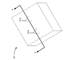
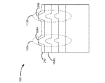
図1Aは、粒子の効果を示すエピタキシャル成長した層を有するデバイス100の斜視図である。図1Aでは、デバイス100は、変形101A及び101Bを有する。図1Bは、A‐A線に沿ってとられたデバイス100の断面図である。
FIG. 1A is a perspective view of a
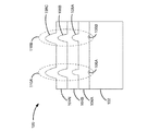
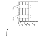
図1Bは、粒子の効果を示すエピタキシャル成長した層を有するデバイス100の断面図である。図1Bのデバイス100は、基板102及び層104A〜104N(本明細書において、集合的には「層104」と呼ばれ、個別には「層104A」、「層104B」などと呼ばれる)から形成される。ここで開示される主題は、任意の特定の基板102に限定されない。基板102は、ガリウムヒ素基板、シリコン基板、又はゲルマニウム系の基板であり得るが、それらに限定されるものではない。
FIG. 1B is a cross-sectional view of
幾つかの実施例では、層104は、エピタキシャル成長する。本明細書で使用されるように、エピタキシャル成長とは、気体又は液体が1つの層の上に堆積することによって複数の層が形成され、それによって、新しく形成された層が、新しく形成された層が、その上に成長したところの層に対して正しく並べられた結晶構造(又はレジストリ(registry))を有することを意味する。本明細書での説明はエピタキシャル成長に言及するが、ここで開示される主題は、層を形成するためのプロセスの他のタイプでも使用され得、エピタキシャル成長に限定されないことは理解されるべきである。 In some embodiments, layer 104 is epitaxially grown. As used herein, epitaxial growth refers to the formation of a plurality of layers by depositing a gas or liquid on a layer so that the newly formed layer is a newly formed layer. Means having a crystal structure (or registry) that is correctly aligned with respect to the layer grown thereon. While the description herein refers to epitaxial growth, it should be understood that the subject matter disclosed herein can be used in other types of processes for forming layers and is not limited to epitaxial growth.
図1Bに戻ると、1以上のプロセスの間に、粒子106A及び/又は粒子106B(本明細書において、集合的に「粒子106」と呼ばれ、個別に「粒子106A」及び「粒子106B」と呼ばれる)が、基板102(又はデバイス100の任意の他の層)上に堆積され得る。粒子106の組成及び源は、変化し得る。例えば、粒子106は、製造施設内で集められた埃又は泥であり得る。別の実施例では、粒子106は、正しく形成しない層を生み出すために使用される気体又は液体の部分であり得る。幾つかのプロセスでは、粒子106は、デバイス100が、金属有機化学気相蒸着チャンバなどのプロセス機械の中へ積み込まれ又はそこから除去されるときに、層104のうちの1つの上に堆積する埃又は泥であり得る。ここで開示される主題は、粒子106が形成される任意の粒子方式又は粒子の組成に限定されない。
Returning to FIG. 1B, during one or more processes,
粒子106が、後続して形成された層が堆積する場合に、デバイス100の1以上の層104上に存在するならば、後続する堆積した層の持ち上げられた輪郭が生み出され得る。図1Bで示される実施例では、層104Aが形成される場合に、持ち上げられた輪郭108Aは、粒子106Bの存在のために生み出される。層104Bは、持ち上げられた輪郭108Bを有し、それは粒子106B及び持ち上げられた輪郭108Aの存在のために生み出される。層104が形成される際に、後続する持ち上げられた輪郭が形成され得、上端層の上の持ち上げられた輪郭、例えば、持ち上げられた輪郭108Cをもたらす。持ち上げられた輪郭108Cは、図1Aの変形101A又は101Bに対応し得、又はそれらの原因であり得る。
If particles 106 are present on one or more layers 104 of
持ち上げられた輪郭108A〜108Cなどの持ち上げられた輪郭は、欠陥領域110A及び110B(本明細書において、集合的に「欠陥領域110」と呼ばれ、個別的に「欠陥領域110A」及び「欠陥領域110B」と呼ばれる)などの、欠陥領域を生み出し得る。処理されない場合に、欠陥領域110は、デバイスがその意図された目的のために動作せず又は適切でない原因となり得る。幾つかの実施例では、欠陥領域110は、適用される圧力が、1以上の層に、部分的又は全体的に隣接する層から剥離させる(又は分離させる)エリアであり得る。他の実施例では、欠陥領域110は、1以上の層104又は基板102に対して構造的損傷をもたらし得る。ここで開示される主題は、欠陥領域110によってもたらされるデバイス100の任意の特定のタイプの損傷又は欠陥に限定されない。
The raised contours, such as raised
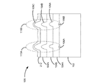
図2は、持ち上げられた輪郭108の高さを低減させるために使用されるプロセス中の保護層212を有するデバイス100の断面図である。図1Bで議論されるように、デバイス100は、粒子106から形成された欠陥領域110を有する。欠陥領域110は、処理されない場合に、デバイス100の動作に影響を与え得るデバイス100のエリアを表し得る。欠陥領域110がデバイス100に影響を有し得る可能性を低減させるために、欠陥領域110内の1以上の持ち上げられた輪郭の高さが低減され得る。
FIG. 2 is a cross-sectional view of the
様々な実施態様では、高さは、組み合わされたCMP/エッチングプロセスを介して低減され得る。幾つかの実施態様では、使用されるエッチング液は、層104の組成に対してとりわけ適切であり得る。更なる実施態様では、エッチング液は、積極的なエッチング速度、すなわち、エッチング液と層104との間の比較的高い化学反応性によってもたらされるエッチングの速度をもたらすように設計された組成又は濃度を有し得る。エッチング液の付加的な側面が、以下により詳細に説明される。 In various embodiments, the height can be reduced through a combined CMP / etch process. In some embodiments, the etchant used may be particularly appropriate for the composition of layer 104. In a further embodiment, the etchant has a composition or concentration designed to provide an aggressive etch rate, i.e., a rate of etch caused by a relatively high chemical reactivity between the etchant and layer 104. Can have. Additional aspects of the etchant are described in more detail below.
デバイス100の様々な部分をエッチング液から保護するために、保護層212は、層104のうちの1つの上で、幾つかの実施例では上端層104Nの上で堆積され得る。上述されたように、幾つかの実施例では、保護層212は、持ち上げられた輪郭を低減させるために使用されるエッチング液に対して比較的不活性であり得る。幾つかの実施例では、保護層212の硬度は、CMP/エッチングプロセスで使用されるエッチング液又はスラリによって影響を受け得る。
In order to protect various portions of the
幾つかの実施例では、スラリは、保護層212を軟らかくし得る酸化剤(又は他の化学物質)を含み得る。保護層212を軟らかくすることは、比較的素早い平坦化を可能にし得る。幾つかの実施例では、保護層212は、例えば、非限定的に、SiO2又はSi3N4から形成されたコンフォーマル層(conformal layer)から成り得る。保護層212は、例えば、非限定的に、プラズマ化学気相堆積法、低圧化学気相堆積法、又はイービーム(e‐beam)若しくは加熱蒸散などの、様々な方法を使用して堆積され得る。以下により詳細に説明されるように、一旦、保護層212が堆積されると、CMP/エッチングプロセスが開始し得る。
In some embodiments, the slurry can include an oxidant (or other chemical) that can soften the
図3は、持ち上げられた輪郭の高さを低減させるための化学機械研磨を経験するデバイス100の断面図である。層104及び保護層212を有するデバイス100は、平坦化機械314内に配置され得る。平坦化機械314は、平坦化パッド316を含み得る。平坦化パッド316は、機械的な方式でデバイス100の部分を除去するために設計された様々な材料から構築され得る。
FIG. 3 is a cross-sectional view of
平坦化機械314は、平坦化パッド316を回転させるように構成され得る。平坦化パッド316が、平坦化動作を提供するための様々な方式で動かされ得ることは、注意されるべきである。例えば、非限定的に、平坦化パッド316は、線形なやり方で振動され得、又は動かされ得る。平坦化パッド316がデバイス100と接触するように回転され、配置される場合に、平坦化パッド316は、機械的研磨を介したデバイス100の層の一部分の除去をもたらし得る。平坦化パッド316によってデバイス100の表面上に適用される圧力とともに、平坦化パッド316の回転の速度は、特定の目的に対して適するように調整され得る。
The flattening
平坦化パッド316は、種々の時間において、デバイス100の特定の部分で機械的に動作するように構成され得、位置決めされ得る。一実施例では、平坦化パッド316は、層104を含んで、デバイスの保護層212の他の部分で動作する前に、頂点320A又は320B(本明細書において、集合的に「頂点320」と呼ばれ、個別的に「頂点320A」及び「頂点320B」と呼ばれる)で機械的に動作するように位置決めされる。
The
スラリ318は、プロセスを円滑にするために、かつ平坦化パッド316によって保護層212から除去された材料を除去するために、使用され得る。スラリ318は、平坦化パッド316によって実行される平坦化プロセスを改良する1以上の液体又は固体を含み得る。例えば、スラリ318は、平坦化パッド316の材料と組み合わされて、平坦化パッド316の機械的除去動作を改良する、研磨粒子を含み得る。別の実施例では、スラリ318は、また、平坦化パッド316によってデバイス100から除去された粒子を除去するための1以上の液体を含み得る。一実施例では、液体は水又は油であり得る。
The
保護層212からの材料の機械的な除去は、また、保護層212の硬度を軟らかくするための酸化剤の使用を介して改良され得る。任意の酸化剤に限定されないが、酸化剤の例は、非限定的に、少なくとも1つのペルオキシ基を含んだ化合物を含む。酸化剤の幾つかの例は、非限定的に、過酸化物、過酸化水素、ハイドロ過酸化水素(hydrohydrogen peroxides)、モノ過硫酸塩及びジ過硫酸塩などの過硫酸塩、過炭酸塩、並びにそれらの酸及び塩類を含む。
The mechanical removal of material from the
処理の間に、デバイス100は、平坦化機械314の中へ積み込まれ得る。平坦化パッド316は、位置Aから位置Bに移動され得、位置Bは、デバイス100の保護層212の表面の少なくとも一部分と接触する。平坦化パッド316がデバイス100と接触してきたときに、又は別の適切な時間に、スラリ318が導入され得る。平坦化パッド316は、平坦化パッド316によって保護層212上に何らかの圧力を提供するために、デバイス100上に圧され得る。
During processing, the
平坦化パッド316は、プロセスの様々な段階で回転され得る。平坦化パッド316が回転する際に、平坦化パッド316の動作は、スラリ318中の構成要素とともに、頂点320A又は320Bから材料を除去し得る。頂点320から材料が除去される際に、頂点320に近接する層104Nの部分は、以下により詳細に説明されるように、スラリ318又は平坦化パッド316に晒され得る。
The
図4は、頂点320の高さを低減させるための化学機械研磨の効果を示すデバイス100の断面図である。デバイス100は、CMP/エッチングプロセスの間の状態で示される。頂点320Aから頂点部分322A及び頂点320Bから頂点部分322Bは、(破線で示されるように)除去されてしまった。頂点部分322A及び322Bの除去を介して、層104Nの上端部分324A及び層104Nの上端部分324Bは、平坦化パッド316及び/又はスラリ318に晒され得る。CMP/エッチングプロセスは、図5で示されるように、継続され得る。
FIG. 4 is a cross-sectional view of the
図5は、持ち上げられた輪郭の高さを低減させるための付加的な化学機械研磨の効果を示すデバイスの断面図である。デバイス100は、プロセスが図4で示された状態を過ぎて継続される場合に、CMP/エッチングプロセスの間の状態で示される。図5では、平坦化パッド316及び/又はスラリ318に晒された上端部分342A及び上端部分324Bのサイズが、増加される。付加的なサイズは、他の可能な恩恵の中から、増加されたエッチング速度を可能にし得る。
FIG. 5 is a cross-sectional view of the device showing the effect of additional chemical mechanical polishing to reduce the height of the raised contour.
図6は、持ち上げられた輪郭の高さを低減させるためのエッチングの効果を示すデバイスの断面図である。図6では、デバイス100は、エッチングプロセスが生じた後の状態で示される。幾つかの実施例では、(図3の)スラリ318中のエッチング液は、層104Nの露出された領域を介して、欠陥領域110に入る。エッチング液は、欠陥領域110の部分を対象とするように構成され得る。
FIG. 6 is a cross-sectional view of the device showing the effect of etching to reduce the height of the raised contour. In FIG. 6, the
例えば、ヒ化物系のIII‐V族の材料の除去のために、スラリ318に対する溶液は、近似的に800:35:4:3の比率の、Nalco 2360 50 nm コロイド状シリカスラリ、H2O、NaOCl、及びクエン酸を含み得る。他の実施例では、ヒ化物系のIII‐V族の材料に対して使用される化学物質は、2000:100:x部の、Nalco 2360 50 nm コロイド状シリカスラリ、H2O2、及びNH4OHであり得、xは3以上である。ここで開示される主題は、任意の特定のエッチング液構成に限定されない。
For example, for removal of arsenide-based III-V materials, a solution to
エッチングプロセスは、欠陥領域110内の材料の全部又は一部を除去し得る。図6では、欠陥領域110内の材料は、基板102上にほとんど完全に除去されているように示されている。種々のエッチングプロセス及び化学物質が、種々の輪郭を生み出し得ることは、注意されるべきである。例えば、欠陥領域110の輪郭は、基板102の上端面から決定されるような比較的垂直な輪郭を有する壁を有するように示される。他のエッチングプロファイル(etching profile)は、特定のエッチング液に応じて、層104の材料などをもたらし得る。ここで開示される主題は、任意の特定のエッチングプロファイルに限定されない。
The etching process may remove all or part of the material in the defect region 110. In FIG. 6, the material in the defect region 110 is shown as being almost completely removed on the
幾つかの実施例では、エッチングプロセスは、欠陥領域110内の材料の一部分のみを除去し得る。例えば、CMP/エッチングプロセスは、欠陥領域110内の材料の一部分のみが除去された場合に、停止され得る。他の実施例では、図6で示された実施例のように、CMP/エッチングプロセスは、欠陥領域110内のほとんど全ての材料が除去されるまで、継続され得る。ここで開示される主題は、除去される材料の特定の量に限定されない。一旦、望ましい量の材料が除去されると、CMP/エッチングプロセスは停止され得、その後、保護層212が除去され得る。
In some embodiments, the etching process may remove only a portion of the material in the defect region 110. For example, the CMP / etch process can be stopped when only a portion of the material in the defect region 110 is removed. In other embodiments, as in the embodiment shown in FIG. 6, the CMP / etch process may be continued until almost all of the material in the defect region 110 has been removed. The subject matter disclosed herein is not limited to a particular amount of material to be removed. Once the desired amount of material has been removed, the CMP / etch process can be stopped and then the
図7は、持ち上げられた輪郭の高さを低減させるために使用されたプロセスの結果を示すデバイス100の断面図である。図7では、デバイス100は、保護層212の除去の後の状態で示されている。保護層212は、様々な技術を使用して除去され得る。例えば、幾つかの保護層212は、フッ化水素(HF)酸などの酸性溶液を使用して除去され得る。ここで開示される主題は、保護層212が除去される任意の特定の方式に限定されない。
FIG. 7 is a cross-sectional view of
CMP/エッチングプロセス及び保護層212の除去の結果として、(図2で示された)持ち上げられた輪郭108の1以上が、除去され得る。幾つかの実施態様では、持ち上げられた輪郭108の1以上が除去され得るので、デバイス100が別のデバイス(又は別の構成要素)に結合された場合に、粒子106によってもたらされる欠陥デバイスの可能性が低減され得る。幾つかの構成では、欠陥領域110内の材料の除去によって生み出された隙間が、別の物質によって部分的に又は全体的に埋められ得る。他の構成では、隙間は、図7で示されたデバイス100内におけるように、触れられないで残される。上述したように、幾つかの例では、エッチング停止層が、使用され得、図8の実施例で説明されるように、材料が欠陥領域からエッチングされる方式に影響を与え得る。
As a result of the CMP / etching process and removal of the
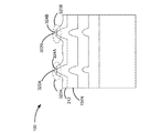
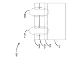
図8は、持ち上げられた輪郭の高さを低減させるために使用されたプロセスの結果を示すエッチング停止層804を有するデバイス800の断面図である。図8では、デバイス800は、基板102並びに層104A及び104Bを含む。幾つかの実施態様では、1以上の層、又は優先的にエッチングプロセスから保護される層のエリアが存在し得る。
FIG. 8 is a cross-sectional view of a
例えば、幾つかの層は、デバイスを形成するためのプロセス内で使用されるエッチング液に反応する材料から形成された構造を有し得る。エッチングプロセスは、他の層に逆方向に影響を与え得る1以上の後続の横たえられた層上で使用され得る。これらの及び他の例では、エッチング停止層804などのエッチング停止層が使用され得る。
For example, some layers may have structures formed from materials that are responsive to the etchant used in the process to form the device. The etching process can be used on one or more subsequent laid layers that can adversely affect other layers. In these and other examples, an etch stop layer such as
幾つかの構成では、エッチング停止層804は、エッチングされる材料とは大幅に異なるエッチング特性を有する材料の層である。例えば、エッチング停止層804は、エッチング液に実質的に化学的に不活性な材料であり得る。別の実施例では、エッチング停止層804は、ドーパントなしの層とは異なるエッチング特性を有するようにドープされたそれ以外のエッチング可能な材料の部分であり得る。
In some configurations, the
一実施例では、シリコンは、ボロンでドープされ得、エッチング停止層を生成する。本明細書で使用されるように、「エッチング停止」は、エッチング停止層804が、幾つかのエッチング停止層はエッチングされる他の領域よりもエッチングプロセスに対するより高い抵抗性を単に有するように設計され得るので、エッチングプロセスから何らの影響も受けないということを意味しないことに留意されたい。ここで開示される主題は、任意の特定の技術に限定されない。
In one example, silicon can be doped with boron to create an etch stop layer. As used herein, “etch stop” is designed so that the
図8では、デバイス800は、材料の部分が欠陥領域110からエッチングされた状態にある。図8で示される構成では、エッチング停止層804は、基板102に向かう方向のエッチングプロセスを低減させるか又は弱めるために、エッチング液に対する障壁を提供した。幾つかの構成では、欠陥領域110内の材料の除去によって生み出された隙間が、別の物質によって部分的に又は全体的に埋められ得る。他の構成では、隙間は、図8で示されたデバイス800内におけるように、触れられないで残される。
In FIG. 8,
図9は、本明細書で開示される少なくとも1つの実施形態による、持ち上げられた輪郭の高さを低減させるためのルーティン900の一構成を示す。特に示されていなければ、図面の中で示されかつ本明細書の中において説明されるよりも多い又は少ない動作が実行され得る。付加的に、特に示されていなければ、これらの動作はまた、本明細書の中において説明されるのとは異なる順序で実行され得る。 FIG. 9 illustrates one configuration of a routine 900 for reducing the height of a raised profile, according to at least one embodiment disclosed herein. Unless otherwise indicated, more or fewer operations may be performed than shown in the drawings and described herein. In addition, unless otherwise indicated, these operations may also be performed in a different order than that described herein.
ルーティン900は、動作902(「基板上に材料の1以上の層をエピタキシャル成長させる」)で開始し、ここで、材料の1以上の層は基板上でエピタキシャル成長する。上述したように、ここで開示される主題は、ここで開示される主題が他のタイプのデバイスで使用され得るように、エピタキシャル成長したデバイスに限定されない。 The routine 900 begins at operation 902 (“epitaxially grow one or more layers of material on a substrate”), where one or more layers of material are epitaxially grown on the substrate. As discussed above, the subject matter disclosed herein is not limited to epitaxially grown devices, such that the subject matter disclosed herein can be used with other types of devices.
ルーティン900は、動作904(「保護層を堆積させる」)へと続き、ここで、保護層は材料の上端層上に堆積される。幾つかの実施態様では、保護層は、後続の平坦化プロセス内のスラリ中で使用されるエッチング液に対して部分的に化学的に不活性である。幾つかの実施例では、保護層は、平坦化パッドがCMP/エッチングプロセス内で使用される場合に、デバイスの1以上の層のエリアを保護するために設計される。保護層の構成、厚さ、及び他の特性は、平坦化パッドが保護層から材料を除去する場合に、1以上の横たわっている層の一部分のみが露出される可能性を増加するように設計され得る。 The routine 900 continues to operation 904 (“deposit protective layer”), where the protective layer is deposited on the top layer of material. In some embodiments, the protective layer is partially chemically inert to the etchant used in the slurry in subsequent planarization processes. In some embodiments, the protective layer is designed to protect areas of one or more layers of the device when a planarization pad is used in the CMP / etch process. The configuration, thickness, and other characteristics of the protective layer are designed to increase the likelihood that only a portion of one or more lying layers will be exposed when the planarization pad removes material from the protective layer. Can be done.
ルーティン900は、動作906(「CMP/エッチングプロセスを実行する」)へと続き、ここで、CMP/エッチングプロセスは、デバイス上で実行される。幾つかの構成では、CMP/エッチングプロセスは、平坦化パッド及びスラリの使用を含む。幾つかの構成では、スラリは、保護層の硬度を低減させる1以上の化学物質から成り得る。これらの構成では、保護層の硬度を低減させることは、材料の一部分を横たわっている層から露出させるために保護層を平坦化する時間及び/又は費用を低減させ得る。 The routine 900 continues to operation 906 (“Perform CMP / etch process”), where the CMP / etch process is performed on the device. In some configurations, the CMP / etch process includes the use of a planarization pad and slurry. In some configurations, the slurry can consist of one or more chemicals that reduce the hardness of the protective layer. In these configurations, reducing the hardness of the protective layer may reduce the time and / or cost of planarizing the protective layer to expose a portion of the material from the underlying layer.
他の構成では、スラリは、保護層の下の1以上の層内の材料との高い程度の化学反応性を有する1以上の化学物質を含み得る。高い程度の化学反応性を有することは、比較的速い(積極的な)エッチングを提供し得る。幾つかの構成では、エッチングプロセスは、持ち上げられた輪郭を有する1以上の欠陥領域から材料を除去するように構成される。1以上の欠陥からの材料の除去は、欠陥デバイスの可能性を低減し得る。 In other configurations, the slurry may include one or more chemicals that have a high degree of chemical reactivity with material in one or more layers below the protective layer. Having a high degree of chemical reactivity can provide a relatively fast (aggressive) etch. In some configurations, the etching process is configured to remove material from one or more defect regions having raised contours. Removal of material from one or more defects can reduce the likelihood of a defective device.
ルーティン900は、動作908(「保護層を除去する」)へと続き、ここで、動作904で堆積された保護層は除去される。幾つかの構成では、保護層は、平坦化プロセスを使用して除去され得る。他の構成では、保護層は、エッチングプロセスで除去され得る。ここで開示される主題は、保護層が除去される任意の特定の方式に限定されない。ルーティン900は、その後、終了し得る。
The routine 900 continues to operation 908 (“Remove Protective Layer”), where the protective layer deposited in
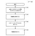
図10は、本明細書で開示される少なくとも1つの実施形態による、図9のルーティン900の動作906などの、化学機械研磨/エッチングプロセスのためのルーティンの一構成を示す。ルーティン1000は、動作1002(「ウエハを平坦化機械の中に受け入れる」)において開始し得、ここで、ウエハは平坦化機械の中に受け入れられる。ここで開示される主題が、他のタイプ及び形状の基板がここで開示される主題の様々な側面で使用され得るように、ウエハとの使用に限定されないことは、注意されるべきである。ウエハは、デバイスを形成する1以上の層を有し得る。ウエハは、また、図9の動作904での実施例によって説明される、保護層を有し得る。
FIG. 10 illustrates one configuration of a routine for a chemical mechanical polishing / etching process, such as
ルーティン1000は、動作1004(「平坦化パッドの配置及び回転を開始する」)へと続き得、ここで、平坦化パッドはウエハに対して位置決めされ、回転される。上述されたように、配置は、特定の平坦化速度をもたらすように、ウエハの保護層に対して特定の圧力を適用するように構成され得る。 The routine 1000 may continue to operation 1004 (“Start placement and rotation of planarization pad”) where the planarization pad is positioned and rotated relative to the wafer. As described above, the arrangement can be configured to apply a specific pressure against the protective layer of the wafer to provide a specific planarization rate.
動作1004に近接して、又は動作1004と同時に、ルーティンは、動作1006(「欠陥領域からの材料をエッチングするように構成された化合物を含むスラリを導入する」)へと続き得、ここで、スラリが導入される。スラリは、1以上の欠陥領域からの材料の積極的なエッチング速度を提供するように構成された1以上の化合物を含み得る。幾つかの構成では、スラリは、また、スラリプロセスを円滑にし、保護層(又は幾つかの構成の他の層)から除去される材料を除去する助けとなるために、蒸留水などの1以上の化合物を含み得る。幾つかの構成では、スラリは、また、保護層の硬度を低減させる1以上の化合物を含み得る。
In proximity to, or at the same time as
ルーティン1000は、動作1008(「欠陥領域のエリアが保護層の下に露出されるまでウエハを平坦化する」)へと続き、ここで、ウエハは欠陥領域のエリアが保護層の下に露出されるまで平坦化される。幾つかの構成では、CMP/エッチングプロセスの平坦化構成要素は、保護層の一部分が、横たわっている層の少なくとも一部分を露出させるために除去されるまで、継続される。一旦、横たわっている層の一部分が露出されると、スラリ中のエッチング化合物は、横たわっている層上でエッチング動作を開始し得る。幾つかの構成では、エッチング化合物は、欠陥領域から除去される材料を対象とするように設計され、それらの領域は、好ましくは、露出された横たわっている材料の一部分である。 The routine 1000 continues to operation 1008 (“planarizes the wafer until the defective area is exposed under the protective layer”), where the wafer is exposed with the defective area under the protective layer. Until flattened. In some configurations, the planarization component of the CMP / etch process is continued until a portion of the protective layer is removed to expose at least a portion of the underlying layer. Once a portion of the lying layer is exposed, the etching compound in the slurry can begin an etching operation on the lying layer. In some configurations, the etching compound is designed to target material that is to be removed from the defect areas, which are preferably a portion of the exposed lying material.
ルーティン1000は、動作1010(「望ましい量の材料が欠陥領域から除去されるまでCMP/エッチングプロセスを続ける」)へと続き、ここで、CMP/エッチングプロセスは、望ましい量の材料が欠陥領域から除去されるまで継続される。幾つかの実施態様では、材料のほとんど全てが欠陥領域から除去され得る。他の実施態様では、比較的少ない量の材料が除去され得、その量は、欠陥領域によってもたらされた持ち上げられた輪郭の高さを低減(又は消去)するように構成され得る。ルーティン1000は、その後、終了し得る。 The routine 1000 continues to operation 1010 (“Continue CMP / etching process until desired amount of material is removed from defect region”), where the CMP / etching process removes the desired amount of material from the defect region. Will continue until In some embodiments, almost all of the material can be removed from the defect area. In other embodiments, a relatively small amount of material can be removed, and the amount can be configured to reduce (or eliminate) the height of the raised contour caused by the defect area. The routine 1000 can then end.
本明細書で開示される少なくとも1つの実施形態による、デバイスの持ち上げられた輪郭の高さを低減させるために使用されるプロセスが実装されたコンピュータを示す。幾つかの構成では、コンピュータ1110は、図3の平坦化機械314などの平坦化機械を制御するために使用される1以上のコンピュータであり得る。図11の中において示されるコンピュータ1100は、1以上の中央処理ユニット(「CPU」)1102、ランダムアクセスメモリ(「RAM」)1106及びリードオンリーメモリ(「ROM」)1108を含むシステムメモリ1104、並びにメモリ1104をCPU1102に結合するシステムバス1110を含む。スタートアップの間などにコンピュータ1100の範囲内の要素の間で情報を移送する助けとなるルーティンを含む基本的な入力/出力システムは、ROM1108の中に記憶され得る。
FIG. 6 illustrates a computer implemented with a process used to reduce the height of a raised contour of a device according to at least one embodiment disclosed herein. FIG. In some configurations, the
CPU1102は、上述のルーティン900及び1000などの、コンピュータ1100の動作のために算術演算及び論理演算を実行する標準的なプログラム可能なプロセッサであり得る。CPU1102は、これらの状態の間で差別化し、かつこれらの状態を変化させるスイッチング要素の操作を介して、1つの離散的な物理状態から次へと移行することによって、動作を実行することができる。スイッチング要素は、概して、フリップフロップなどの2つのバイナリー状態のうちの1つを維持する電気回路、及び論理ゲートなどの1以上の他のスイッチング要素の状態の論理結合に基づいて、出力状態を提供する電気回路を含み得る。これらの基本的なスイッチング要素は、レジスタ、アダーサブトラクター(adders‐subtractors)、数値演算ユニット、浮動小数点演算ユニット、及び同様なものを含む、より複雑な論理回路を形成するために組み合され得る。
コンピュータ1100はまた、大容量記憶装置1112を含み得る。大容量記憶装置は、光ディスク、磁気記憶装置、又は半導体記憶装置であり得る。大容量記憶装置1112は、平坦化機械314の動作を制御するように構成されたCMP/エッチングプロセス指示命令1114を記憶するために動作可能である。
The
コンピュータ1100は、記憶されている情報を反映するために、大容量記憶装置1112の物理状態を変容させることによって、プログラム及びデータを大容量記憶装置1112に記憶させることができる。物理状態の具体的な変容は、本開示の種々の実装において、様々な要因に応じ得る。そのような要因の実施例は、大容量記憶装置1112が1次若しくは2次の記憶、及び同様なものとして特徴付けられるか否かに関わらず、大容量記憶装置1112を実装するために使用される技術を含み得るが、それらに限定されるものではない。
The
例えば、コンピュータ1100は、磁気ディスクドライブ装置の範囲内の特定の場所の磁気的な特性、光学式記憶装置の中の特定の場所の反射特性又は屈折特性、又は特定のキャパシタ、トランジスタ、若しくは半導体記憶装置の中の他の個別部品の電気的な特性を変化させるために、記憶コントローラを介して指示命令を発行することによって、大容量記憶装置1112に情報を記憶させることができる。物理媒体の他の変容は、本開示の範囲及び精神から逸脱することなしに、この説明を容易にするためだけに提供された上述の実施例を用いて可能となる。コンピュータ1100はさらに、大容量記憶装置1112の範囲内の1以上の特定の場所の物理状態又は特性を検出することによって、大容量記憶装置1112から情報を読み出すことができる。
For example, the
ランダムアクセスメモリ1106、リードオンリーメモリ1108、又は大容量記憶装置1112は、コンピュータ可読記憶媒体として動作可能である。本開示の様々な側面は、RAM、ROM、EPROM、EEPROM、フラッシュメモリ若しくは他の半導体メモリ技術、CD‐ROM、デジタル多用途ディスク(「DVD」)、HD‐DVD、BLU‐RAY、若しくは他の光学的な記憶装置、磁気カセット、磁気テープ、磁気ディクス記憶装置若しくは他の磁気記憶装置、又は望ましい情報を記憶するために使用されることができ、かつコンピュータ1100によってアクセスされることができる任意の他の媒体などの他のタイプのコンピュータ可読記憶媒体に記憶され得るが、それらに限定されるものではない。本開示の下に特許請求の範囲が解釈される場合、コンピュータ可読記憶媒体は波又は信号の形をとるエネルギーを含まないことは、理解されるべきである。
The random access memory 1106, the read only memory 1108, or the
コンピュータ1100はまた、キーボード、マウス、又はエレクトロニックスタイラスを含む、任意の数の他の装置から入力を受信し、かつその入力を処理するための、入力/出力コントローラ1116を含み得る。同様に、入力/出力コントローラ1116は、ディスプレースクリーン、プリンター、又は他のタイプの出力装置に出力を提供することができる。幾つかの実施態様では、入力/出力コントローラ1116は、平坦化パッド316、又はスラリ318を導入するための1以上のインジェクタを制御する、1以上の機構の動作を制御し得る。1以上の実施形態は、適正に構成されたコンピュータ装置によって読まれる場合に、指示命令が、持ち上げられた輪郭の高さを低減させることに関して動作を実行するための平坦化機械314に提供され得るような、コンピュータ可読記憶媒体を含み得る。
更に、本開示は、以下の条項による実施例を含む。 Furthermore, the present disclosure includes examples according to the following clauses.
デバイスを処理する方法であって、基板上に材料の少なくとも1つの層をエピタキシャル成長させることであって、材料の前記少なくとも1つの層は欠陥領域を備える、エピタキシャル成長させること、材料の前記少なくとも1つの層の少なくとも一部分上に保護層を堆積させること、並びに前記デバイスを平坦化機械の中に受け入れること、平坦化パッドを回転させること、前記欠陥領域の少なくとも一部分からの材料をエッチングするように構成された化合物を含んだスラリを導入すること、前記欠陥領域のエリアが前記スラリに晒されるまで前記デバイスを平坦化すること、及び望ましい量の材料が前記欠陥領域から除去されるまで、化学機械平坦化(「CMP」)/エッチングプロセスを継続することを含んだ、CMP/エッチングプロセスを実行することを含む、方法。 A method of processing a device, comprising epitaxially growing at least one layer of material on a substrate, wherein the at least one layer of material comprises a defect region, epitaxially growing, the at least one layer of material. And depositing a protective layer on at least a portion of the substrate, and receiving the device into a planarization machine, rotating the planarization pad, and etching material from at least a portion of the defect region. Introducing a slurry containing a compound, planarizing the device until an area of the defect area is exposed to the slurry, and chemical mechanical planarization until a desired amount of material is removed from the defect area ( "CMP") / CMP / etch, including continuing the etching process Comprising performing a process, method.
前記平坦化機械から前記デバイスを除去することを更に含む、前記方法。 The method further comprising removing the device from the planarization machine.
前記CMP/エッチングプロセスの後で、残っている前記保護層の少なくとも一部分を除去することを更に含む、先行する条項のいずれかに記載の方法。 The method of any preceding clause, further comprising removing at least a portion of the remaining protective layer after the CMP / etching process.
前記CMP/エッチングプロセスの後で残っている前記保護層の少なくとも一部分を除去することは、前記保護層をエッチングするために、前記保護層の少なくとも一部分にフッ化水素酸を導入することを含む、先行する条項のいずれかに記載の方法。 Removing at least a portion of the protective layer remaining after the CMP / etching process comprises introducing hydrofluoric acid into at least a portion of the protective layer to etch the protective layer; A method as described in any of the preceding clauses.
前記スラリは、前記保護層の硬度を低減させるように構成された化合物を含む、先行する条項のいずれかに記載の方法。 The method of any preceding clause, wherein the slurry comprises a compound configured to reduce the hardness of the protective layer.
前記保護層の前記硬度を低減させるように構成された前記化合物は、酸化剤を含む、先行する条項のいずれかに記載の方法。 The method of any preceding clause, wherein the compound configured to reduce the hardness of the protective layer comprises an oxidizing agent.
前記酸化剤は、過酸化物、過酸化水素、ハイドロ過酸化水素、モノ過硫酸塩及びジ過硫酸塩などの過硫酸塩、過炭酸塩、並びにそれらの酸及び塩類を含む、先行する条項のいずれかに記載の方法。 The oxidizing agent includes peroxides, hydrogen peroxide, hydrohydrogen peroxide, persulfates such as monopersulfates and dipersulfates, percarbonates, and their acids and salts. The method according to any one.
前記スラリは、前記欠陥領域内の材料を対象とするように構成されたエッチング液を含む、先行する条項のいずれかに記載の方法。 The method of any preceding clause, wherein the slurry includes an etchant configured to target material in the defect area.
前記エッチング液は、近似的に800:35:4:3の比率の、コロイド状シリカスラリ、H2O、NaOCl、及びクエン酸を含む、先行する条項のいずれかに記載の方法。 The method of any preceding clause, wherein the etchant comprises colloidal silica slurry, H 2 O, NaOCl, and citric acid in a ratio of approximately 800: 35: 4: 3.
前記エッチング液は、近似的に2000:100:xの比率の、コロイド状シリカスラリ、H2O2、及びNH4OHを含み、xは3以上である、先行する条項のいずれかに記載の方法。 The method of any preceding clause, wherein the etchant comprises colloidal silica slurry, H 2 O 2 , and NH 4 OH in a ratio of approximately 2000: 100: x, wherein x is 3 or greater. .
平坦化機械のプロセッサによって実行された場合に、前記平坦化機械に、少なくとも1つのエピタキシャル成長した層及び少なくとも1つの保護層を有するウエハを受け入れさせ、前記少なくとも1つのエピタキシャル成長した層は欠陥領域を含み、並びに平坦化パッドを回転させ、前記欠陥領域の少なくとも一部分からの材料をエッチングするように構成された化合物を含んだスラリを導入し、前記欠陥領域のエリアが前記スラリに晒されるまでデバイスの前記欠陥領域を平坦化し、及び望ましい量の材料が前記欠陥領域から除去されるまで化学機械平坦化(「CMP」)/エッチングプロセスを続けることを含んだ、CMP/エッチングプロセスを実行させる、コンピュータ可読記憶媒体に記憶された指示命令を有する、コンピュータ可読記憶媒体。 When executed by a processor of a planarization machine, causes the planarization machine to receive a wafer having at least one epitaxially grown layer and at least one protective layer, the at least one epitaxially grown layer including a defect region; And rotating a planarization pad to introduce a slurry containing a compound configured to etch material from at least a portion of the defect region, and the defect of the device until the area of the defect region is exposed to the slurry A computer readable storage medium for performing a CMP / etching process comprising planarizing a region and continuing a chemical mechanical planarization (“CMP”) / etching process until a desired amount of material is removed from the defect region With computer-directed instructions Storage medium.
前記平坦化機械から前記ウエハを除去するための指示命令を更に含む、前記コンピュータ可読記憶媒体。 The computer readable storage medium further comprising instruction instructions for removing the wafer from the planarization machine.
前記スラリは、前記少なくとも1つの保護層の硬度を低減させるように構成された化合物を含む、先行する条項のいずれかに記載のコンピュータ可読記憶媒体。 The computer readable storage medium of any preceding clause, wherein the slurry includes a compound configured to reduce the hardness of the at least one protective layer.
前記保護層の前記硬度を低減させるように構成された前記化合物は、酸化剤を含む、先行する条項のいずれかに記載のコンピュータ可読記憶媒体。 The computer readable storage medium of any preceding clause, wherein the compound configured to reduce the hardness of the protective layer comprises an oxidant.
前記酸化剤は、過酸化物、過酸化水素、ハイドロ過酸化水素、モノ過硫酸塩及びジ過硫酸塩などの過硫酸塩、過炭酸塩、並びにそれらの酸及び塩類を含む、先行する条項のいずれかに記載のコンピュータ可読記憶媒体。 The oxidizing agent includes peroxides, hydrogen peroxide, hydrohydrogen peroxide, persulfates such as monopersulfates and dipersulfates, percarbonates, and their acids and salts. A computer-readable storage medium according to any one of the above.
前記スラリは、前記欠陥領域内の材料を対象とするように構成されたエッチング液を含む、先行する条項のいずれかに記載のコンピュータ可読記憶媒体。 The computer readable storage medium of any preceding clause, wherein the slurry includes an etchant configured to target material in the defect area.
前記エッチング液は、近似的に800:35:4:3の比率の、コロイド状シリカスラリ、H2O、NaOCl、及びクエン酸を含む、先行する条項のいずれかに記載のコンピュータ可読記憶媒体。 The computer-readable storage medium of any preceding clause, wherein the etchant comprises colloidal silica slurry, H 2 O, NaOCl, and citric acid in a ratio of approximately 800: 35: 4: 3.
前記エッチング液は、近似的に2000:100:xの比率の、コロイド状シリカスラリ、H2O2、及びNH4OHを含み、xは3以上である、先行する条項のいずれかに記載のコンピュータ可読記憶媒体。 The computer according to any of the preceding clauses, wherein the etchant comprises colloidal silica slurry, H 2 O 2 , and NH 4 OH in a ratio of approximately 2000: 100: x, where x is 3 or greater. A readable storage medium.
化学機械研磨/エッチングプロセスのためのスラリであって、保護層の硬度を低減させるように構成された化合物、及びデバイスの欠陥領域内の材料を対象とするように構成されたエッチング液を含む、スラリ。 A slurry for a chemical mechanical polishing / etching process, comprising a compound configured to reduce the hardness of a protective layer, and an etchant configured to target material in a defective region of the device, Slurry.
前記エッチング液は、近似的に800:35:4:3の比率の、コロイド状シリカスラリ、H2O、NaOCl、並びにクエン酸、及び近似的に2000:100:xの比率の、コロイド状シリカスラリ、H2O2、及びNH4OHを含み、xは3以上である、前記スラリ。 The etchant is approximately 800: 35: 4: 3 ratio colloidal silica slurry, H 2 O, NaOCl, and citric acid, and approximately 2000: 100: x ratio colloidal silica slurry, The slurry comprising H 2 O 2 and NH 4 OH, wherein x is 3 or more.
上述の主題は、例示目的によってのみ提供され、かつ限定的に解釈されるべきではない。例示されかつ説明された例示的な実施形態及び用途を追従することなしに、かつ以下の特許請求の範囲の中で説明される本開示の真の精神及び範囲から逸脱することなしに、様々な修正及び変形が本主題に対して行われ得る。
The subject matter described above is provided by way of illustration only and should not be construed as limiting. Various examples without following the exemplary embodiments and applications illustrated and described, and without departing from the true spirit and scope of the present disclosure as set forth in the following claims. Modifications and variations can be made to the present subject matter.
Claims (20)
基板上に材料の少なくとも1つの層をエピタキシャル成長させることであって、材料の前記少なくとも1つの層は欠陥領域を備える、エピタキシャル成長させること、
材料の前記少なくとも1つの層の少なくとも一部分上に保護層を堆積させること、並びに
化学機械平坦化(「CMP」)/エッチングプロセスであって、
前記デバイスを平坦化機械の中に受け入れること、
平坦化パッドを回転させること、
前記欠陥領域の少なくとも一部分からの材料をエッチングするように構成された化合物を含んだスラリを導入すること、
前記欠陥領域のエリアが前記スラリに晒されるまで前記デバイスを平坦化すること、及び
望ましい量の材料が前記欠陥領域から除去されるまで、前記CMP/エッチングプロセスを継続することを含んだ、CMP/エッチングプロセスを実行することを含む、方法。 A method of processing a device, comprising:
Epitaxially growing at least one layer of material on a substrate, wherein the at least one layer of material comprises a defect region;
Depositing a protective layer on at least a portion of said at least one layer of material, as well as a chemical mechanical planarization (“CMP”) / etching process comprising:
Receiving the device in a flattening machine;
Rotating the flattening pad,
Introducing a slurry comprising a compound configured to etch material from at least a portion of the defect region;
Planarizing the device until the area of the defective area is exposed to the slurry, and continuing the CMP / etching process until a desired amount of material is removed from the defective area. Performing an etching process.
少なくとも1つのエピタキシャル成長した層及び少なくとも1つの保護層を有するウエハを受け入れさせ、前記少なくとも1つのエピタキシャル成長した層は欠陥領域を含み、並びに
化学機械平坦化(「CMP」)/エッチングプロセスであって、
平坦化パッドを回転させ、
前記欠陥領域の少なくとも一部分からの材料をエッチングするように構成された化合物を含んだスラリを導入し、
前記欠陥領域のエリアが前記スラリに晒されるまで前記欠陥領域を平坦化し、及び
望ましい量の材料が前記欠陥領域から除去されるまでCMP/エッチングプロセスを継続することを含んだ、CMP/エッチングプロセスを実行させる、コンピュータ可読記憶媒体に記憶された指示命令を有する、コンピュータ可読記憶媒体。 Instruction instructions stored in a computer readable storage medium when executed by a processor of the flattening machine,
Receiving a wafer having at least one epitaxially grown layer and at least one protective layer, the at least one epitaxially grown layer including a defect region, and a chemical mechanical planarization (“CMP”) / etching process,
Rotate the flattening pad,
Introducing a slurry comprising a compound configured to etch material from at least a portion of the defect region;
CMP / etching process comprising planarizing the defect area until the area of the defect area is exposed to the slurry and continuing the CMP / etch process until a desired amount of material is removed from the defect area. A computer readable storage medium having instruction instructions stored on the computer readable storage medium for execution.
保護層の硬度を低減させるように構成された化合物、及び
デバイスの欠陥領域内の材料を対象とするように構成されたエッチング液を含む、スラリ。 A slurry for a chemical mechanical polishing / etching process comprising:
A slurry comprising a compound configured to reduce the hardness of the protective layer and an etchant configured to target material in a defect region of the device.
The etchant may be a colloidal silica slurry in a ratio of approximately 800: 35: 4: 3, H 2 O, NaOCl, and citric acid, or a colloidal silica slurry in a ratio of approximately 2000: 100: x, H 2 O 2, and includes NH 4 OH, x is 3 or more, slurry of claim 19.
Applications Claiming Priority (2)
| Application Number | Priority Date | Filing Date | Title |
|---|---|---|---|
| US14/556,337 US9431261B2 (en) | 2014-12-01 | 2014-12-01 | Removal of defects by in-situ etching during chemical-mechanical polishing processing |
| US14/556,337 | 2014-12-01 |
Publications (3)
| Publication Number | Publication Date |
|---|---|
| JP2016129221A true JP2016129221A (en) | 2016-07-14 |
| JP2016129221A5 JP2016129221A5 (en) | 2017-05-18 |
| JP6151340B2 JP6151340B2 (en) | 2017-06-21 |
Family
ID=54542064
Family Applications (1)
| Application Number | Title | Priority Date | Filing Date |
|---|---|---|---|
| JP2015234383A Active JP6151340B2 (en) | 2014-12-01 | 2015-12-01 | Defect removal by in situ etching during chemical mechanical polishing |
Country Status (4)
| Country | Link |
|---|---|
| US (1) | US9431261B2 (en) |
| EP (2) | EP3029717A1 (en) |
| JP (1) | JP6151340B2 (en) |
| TW (1) | TWI680508B (en) |
Citations (3)
| Publication number | Priority date | Publication date | Assignee | Title |
|---|---|---|---|---|
| JP2000315669A (en) * | 1999-03-18 | 2000-11-14 | Samsung Electronics Co Ltd | Chemical-mechanical polishing method using double-polish preventing layer |
| JP2006278981A (en) * | 2005-03-30 | 2006-10-12 | Fujimi Inc | Abrasive for single crystal surface and polishing method |
| US7951719B2 (en) * | 2004-02-25 | 2011-05-31 | Hrl Laboratories, Llc | Self-masking defect removing method |
Family Cites Families (6)
| Publication number | Priority date | Publication date | Assignee | Title |
|---|---|---|---|---|
| JP2000031163A (en) | 1998-07-13 | 2000-01-28 | Denso Corp | Semiconductor device and fabrication thereof |
| US6417109B1 (en) * | 2000-07-26 | 2002-07-09 | Aiwa Co., Ltd. | Chemical-mechanical etch (CME) method for patterned etching of a substrate surface |
| DE102007019565A1 (en) | 2007-04-25 | 2008-09-04 | Siltronic Ag | Semiconductor disk one-sided polishing method for e.g. memory cell, involves providing polishing agent between polishing cloth and disk, where polishing agent has alkaline component and component dissolving germanium |
| TWI548728B (en) | 2011-08-01 | 2016-09-11 | 巴斯夫歐洲公司 | A process for the manufacture of semiconductor devices comprising the chemical mechanical polishing of elemental germanium and/or si1-x gex material in the presence of a cmp composition comprising a specific organic compound |
| JP6050934B2 (en) | 2011-11-08 | 2016-12-21 | 株式会社フジミインコーポレーテッド | Polishing composition, polishing method using the same, and substrate manufacturing method |
| FR2994615A1 (en) * | 2012-08-14 | 2014-02-21 | Commissariat Energie Atomique | Method for planarizing epitaxial layer of structure to form photovoltaic cell in e.g. photovoltaic fields, involves removing masking layer to obtain surface of epitaxial layer whose protuberances exhibit height lower than height threshold |
-
2014
- 2014-12-01 US US14/556,337 patent/US9431261B2/en active Active
-
2015
- 2015-11-12 EP EP15194346.1A patent/EP3029717A1/en not_active Ceased
- 2015-11-12 EP EP23168320.2A patent/EP4235751A3/en active Pending
- 2015-12-01 JP JP2015234383A patent/JP6151340B2/en active Active
- 2015-12-01 TW TW104140023A patent/TWI680508B/en active
Patent Citations (3)
| Publication number | Priority date | Publication date | Assignee | Title |
|---|---|---|---|---|
| JP2000315669A (en) * | 1999-03-18 | 2000-11-14 | Samsung Electronics Co Ltd | Chemical-mechanical polishing method using double-polish preventing layer |
| US7951719B2 (en) * | 2004-02-25 | 2011-05-31 | Hrl Laboratories, Llc | Self-masking defect removing method |
| JP2006278981A (en) * | 2005-03-30 | 2006-10-12 | Fujimi Inc | Abrasive for single crystal surface and polishing method |
Also Published As
| Publication number | Publication date |
|---|---|
| EP3029717A1 (en) | 2016-06-08 |
| TW201631652A (en) | 2016-09-01 |
| JP6151340B2 (en) | 2017-06-21 |
| EP4235751A3 (en) | 2023-11-15 |
| EP4235751A2 (en) | 2023-08-30 |
| US9431261B2 (en) | 2016-08-30 |
| US20160155644A1 (en) | 2016-06-02 |
| TWI680508B (en) | 2019-12-21 |
Similar Documents
| Publication | Publication Date | Title |
|---|---|---|
| JP5070196B2 (en) | Stabilized photoresist composition for etching process | |
| US7452817B2 (en) | CMP method providing reduced thickness variations | |
| CN104752363B (en) | The forming method of flash memory | |
| TWI396232B (en) | Method of manufacturing a semiconductor device and a semiconductor manufacturing equipment | |
| JP5025508B2 (en) | Method for removing polysilicon film and storage medium | |
| KR102660772B1 (en) | Process systems and platforms for wet atomic layer etching using self-controlled and solubility-limited reactions | |
| JP5266496B2 (en) | Chamfer board routing method | |
| TWI494998B (en) | Substrate handling method | |
| TWI666697B (en) | Substrate processing method, substrate processing device and memory medium | |
| US20160035598A1 (en) | Method for chemical planarization and chemical planarization apparatus | |
| JP2008091883A (en) | Method of manufacturing semiconductor device and apparatus for manufacturing semiconductor device | |
| CN101197264B (en) | Forming method of L-shaped side wall | |
| JP6151340B2 (en) | Defect removal by in situ etching during chemical mechanical polishing | |
| Kim et al. | Development of novel multi-selective slurry with mechanically driven etching for through silicon via chemical mechanical polishing | |
| US20030124861A1 (en) | Method for manufacturing metal line contact plug semiconductor device | |
| TW506008B (en) | Semiconductor wafer manufacturing process | |
| CN104681496B (en) | The forming method of semiconductor structure | |
| CN113725221B (en) | Method for manufacturing flash memory device | |
| CN111066125A (en) | Etching and mechanically grinding film layers stacked on a semiconductor substrate | |
| JP2022044147A (en) | Method for adjusting surface shape of wafer | |
| KR20050079316A (en) | Method for processing a thin film in a semiconductor device | |
| TW403965B (en) | The method of etching the silicon nitride to form the spacer | |
| KR20120042579A (en) | Method for forming semiconductor device | |
| KR20080086660A (en) | Method for chemical mechanical polishing in semiconductor device | |
| JPH0234925A (en) | Manufacture of semiconductor device |
Legal Events
| Date | Code | Title | Description |
|---|---|---|---|
| A521 | Request for written amendment filed |
Free format text: JAPANESE INTERMEDIATE CODE: A523 Effective date: 20170321 |
|
| A621 | Written request for application examination |
Free format text: JAPANESE INTERMEDIATE CODE: A621 Effective date: 20170321 |
|
| A871 | Explanation of circumstances concerning accelerated examination |
Free format text: JAPANESE INTERMEDIATE CODE: A871 Effective date: 20170321 |
|
| A975 | Report on accelerated examination |
Free format text: JAPANESE INTERMEDIATE CODE: A971005 Effective date: 20170417 |
|
| TRDD | Decision of grant or rejection written | ||
| A01 | Written decision to grant a patent or to grant a registration (utility model) |
Free format text: JAPANESE INTERMEDIATE CODE: A01 Effective date: 20170425 |
|
| A61 | First payment of annual fees (during grant procedure) |
Free format text: JAPANESE INTERMEDIATE CODE: A61 Effective date: 20170524 |
|
| R150 | Certificate of patent or registration of utility model |
Ref document number: 6151340 Country of ref document: JP Free format text: JAPANESE INTERMEDIATE CODE: R150 |
|
| R250 | Receipt of annual fees |
Free format text: JAPANESE INTERMEDIATE CODE: R250 |
|
| R250 | Receipt of annual fees |
Free format text: JAPANESE INTERMEDIATE CODE: R250 |
|
| R250 | Receipt of annual fees |
Free format text: JAPANESE INTERMEDIATE CODE: R250 |
|
| R250 | Receipt of annual fees |
Free format text: JAPANESE INTERMEDIATE CODE: R250 |
|
| R250 | Receipt of annual fees |
Free format text: JAPANESE INTERMEDIATE CODE: R250 |
