JP2016124733A - Production method of glass gob, and production apparatus of glass gob - Google Patents
Production method of glass gob, and production apparatus of glass gob Download PDFInfo
- Publication number
- JP2016124733A JP2016124733A JP2014266389A JP2014266389A JP2016124733A JP 2016124733 A JP2016124733 A JP 2016124733A JP 2014266389 A JP2014266389 A JP 2014266389A JP 2014266389 A JP2014266389 A JP 2014266389A JP 2016124733 A JP2016124733 A JP 2016124733A
- Authority
- JP
- Japan
- Prior art keywords
- mold
- glass
- glass lump
- lump
- tray
- Prior art date
- Legal status (The legal status is an assumption and is not a legal conclusion. Google has not performed a legal analysis and makes no representation as to the accuracy of the status listed.)
- Pending
Links
Images


Landscapes
- Re-Forming, After-Treatment, Cutting And Transporting Of Glass Products (AREA)
Abstract
Description
本発明は、ガラス塊の製造方法、及び、ガラス塊の製造装置に関し、特に、上方に向かって拡張して開口する内部空間を有する成形型を用い、内部空間内で浮上成形によりほぼ球形にガラス塊を成形するガラス塊の製造方法、及び、ガラス塊の製造装置に関する。 The present invention relates to a glass lump manufacturing method and a glass lump manufacturing apparatus, and in particular, a glass having a substantially spherical shape by floating molding in an internal space using a mold having an internal space that expands and opens upward. The present invention relates to a glass lump manufacturing method for forming a lump and a glass lump manufacturing apparatus.
従来より、加熱状態のガラス塊(プリフォーム)を成形型によりプレス成形し、プレス成形型の成形面を転写することにより、レンズ等の光学素子を製造することが行われている。ガラス塊の製造方法として、上方に向かって拡張して開口する内部空間を有する成形型を用い、内部空間内で浮上成形によりほぼ球形に成形する方法(浮上成形法)が知られている。 2. Description of the Related Art Conventionally, an optical element such as a lens is manufactured by pressing a heated glass block (preform) with a molding die and transferring a molding surface of the press molding die. As a method for producing a glass lump, there is known a method (floating molding method) in which a molding die having an internal space that expands upward and opens and is formed into a substantially spherical shape by floating molding in the internal space.
このようにして成形されたガラス塊を成形型から取り出す方法として、例えば、特許文献1(特許第4346624号)には、成形型の内部空間内のガラス塊に向けて風圧を加えて、ガラス塊を成形型から吹き飛ばしてガラス塊の取出しを行うことが開示されている。特許文献1記載の方法によれば、ロボット等によりガラス塊を保持する必要がなくなるため、タクトタイムを短くし、ガラス塊の生産性を向上させることができる。 As a method for taking out the glass lump formed in this way from the mold, for example, in Patent Document 1 (Patent No. 4346624), wind pressure is applied toward the glass lump in the inner space of the mold to It is disclosed that the glass lump is taken out by blowing the glass from the mold. According to the method described in Patent Document 1, since it is not necessary to hold the glass block by a robot or the like, the tact time can be shortened and the productivity of the glass block can be improved.
特許文献1記載の方法は、ガラス塊の重量が比較的に軽い場合、具体的には重量が30mg以下の場合には非常に効果的である。しかしながら、ガラス塊の重量が30mgを超える場合には、ガラス塊を風圧で吹き飛ばすことが困難となる。他方、実際に、カメラ等に用いられているレンズは2mm径程度の極小径から10数mm径程度の比較的に中口径に至るまで様々である。 The method described in Patent Document 1 is very effective when the weight of the glass block is relatively light, specifically when the weight is 30 mg or less. However, when the weight of the glass lump exceeds 30 mg, it is difficult to blow off the glass lump with wind pressure. On the other hand, lenses used in cameras and the like actually vary from a minimum diameter of about 2 mm to a relatively medium diameter of about several tens of mm.
特許文献1記載の方法は、レンズを製造するために必要となるガラス塊のうち、軽量のガラス塊を取り出す場合には有効であるが、比較的に重いガラス塊を取り出す場合には必ずしも適しているとはいえない。 The method described in Patent Document 1 is effective when taking out a light glass lump out of glass lump necessary for manufacturing a lens, but is not always suitable when taking out a relatively heavy glass lump. I can't say.
本発明は、上記の課題に鑑みなされたものであり、成形されたガラス塊の重量によらず、確実にガラス塊を成形型から取り出すことができるようにする、ガラス塊の製造方法、及び、ガラス塊の製造装置を提供するものである。 The present invention has been made in view of the above problems, and allows a glass lump to be reliably taken out of a mold without depending on the weight of the formed glass lump, and a glass lump manufacturing method, and An apparatus for producing a glass lump is provided.
本発明のガラス塊の製造方法は、上方に向かって拡張して開口する内部空間を有する成形型を用い、内部空間内で浮上成形によりほぼ球形にガラス塊を成形する成形工程と、成形型を傾斜させて、成形型の内部空間からガラス塊を成形型の下方に配置された収納容器に移送する移送工程と、を備える。 The method for producing a glass lump according to the present invention uses a molding die having an internal space that expands and opens upward, and forms a glass lump into a substantially spherical shape by floating molding in the internal space, and a molding die A transfer step of inclining and transferring the glass lump from the internal space of the mold to a storage container disposed below the mold.
上記構成の本発明によれば、例えば、成形型傾斜機構等により成形型を傾斜させることにより、成形されたガラス塊を収納容器に移送しているため、ガラス塊の重量によらず、確実に成形型からガラス塊を移送することができる。 According to the present invention having the above configuration, for example, the molded glass lump is transferred to the storage container by tilting the mold by a mold tilting mechanism or the like, so that it can be reliably performed regardless of the weight of the glass lump. The glass block can be transferred from the mold.
本発明において、好ましくは、ガラス塊は、摩耗度が400以上のガラス材料からなる。また、本発明において好ましくは、ガラス材料はフツリン酸塩ガラスである。 In the present invention, the glass lump is preferably made of a glass material having a wear degree of 400 or more. In the present invention, preferably, the glass material is a fluorophosphate glass.
摩耗度が400以上のガラス材料、例えば、フツリン酸塩ガラスのガラス塊は、衝撃等により傷がつきやすい。従来、ガラス塊の成形型からの取出し方法として、先端部に吸引治具を備えた搬送機構により、吸引治具によりガラス塊を吸着し、成形型から取り出す方法が用いられることがあった。しかしながら、このように吸引治具によりフツリン酸塩ガラス等のガラス塊を吸着すると、ガラス塊の表面にひびや傷が生じるという問題がある。これに対して、上記構成の本発明によれば、ガラス塊に治具等を接触させることなくガラス塊を移送することができるため、傷がつきやすいガラス材料からなるガラス塊であっても、損傷することなく移送できる。 A glass material having a wear degree of 400 or more, for example, a glass lump of fluorophosphate glass, is easily damaged by impact or the like. Conventionally, as a method for taking out a glass lump from a mold, there has been used a method in which a glass lump is adsorbed by a suction jig and taken out from the mold by a transport mechanism having a suction jig at the tip. However, when a glass lump such as fluorophosphate glass is adsorbed by the suction jig in this way, there is a problem that cracks and scratches are generated on the surface of the glass lump. On the other hand, according to the present invention of the above configuration, since the glass lump can be transferred without bringing a jig or the like into contact with the glass lump, even if it is a glass lump made of a glass material that is easily damaged, Can be transported without damage.
本発明において、好ましくは、収納容器の少なくともガラス塊と接触する部分が、ロックウェル硬さがR50未満の材料で形成されている。また、本発明において、好ましくは、成形型と収納容器との間に、ガラス塊を搬送する搬送部材が設けられ、収納容器及び搬送部材は、少なくともガラス塊と接触する部分が、ロックウェル硬さがR50未満の材料で形成されている。 In the present invention, preferably, at least a portion of the storage container that comes into contact with the glass block is formed of a material having a Rockwell hardness of less than R50. In the present invention, preferably, a conveying member for conveying the glass lump is provided between the mold and the storage container, and at least a portion of the storage container and the conveying member that contacts the glass lump has a Rockwell hardness. Is formed of a material of less than R50.
上記構成の本発明によれば、ガラス塊が成形型からトレイ上に移送された際に、ガラス塊に傷が付くことを防止できる。 According to this invention of the said structure, when a glass lump is transferred on a tray from a shaping | molding die, it can prevent that a glass lump is damaged.
本発明のガラス塊の製造装置は、上方に向かって拡張して開口する内部空間を有し、内部空間内で浮上成形によりほぼ球形にガラス塊を成形する成形型と、成形型の内部空間からガラス塊を収納容器に移送するように成形型を傾斜させる成形型傾斜機構と、を備える。 The glass lump manufacturing apparatus of the present invention has an internal space that expands and opens upward, and a mold for forming the glass lump into a substantially spherical shape by float forming in the internal space, and an internal space of the mold A mold tilt mechanism that tilts the mold so as to transfer the glass block to the storage container.
本発明によれば、成形されたガラス塊の重量によらず、確実にガラス塊を成形型から取り出すことができる。 According to the present invention, the glass lump can be reliably taken out from the mold regardless of the weight of the formed glass lump.
以下、本発明の第1実施形態のガラス塊の製造方法、及び、ガラス塊の製造装置を図面を参照しながら詳細に説明する。
なお、本明細書において、ほぼ球形のガラス塊は、球形のガラス塊のみならず、多面体のガラス塊を含む。ここで、ガラス塊とは、熔融ガラスが固化されたものであって、流動性を失った状態にあるガラスをいう。例えば、プリフォームなどのガラス材料を所定の形状に成形したものを指す。また、熔融ガラスとは、熔融ガラス供給装置から成形型内に供給され、浮上成形により、流動性がなくなる直前までの状態にあるガラスをいう。本明細書では、ガラス塊と熔融ガラスとは、同じ符号を用いて説明する。
Hereinafter, a glass lump manufacturing method and a glass lump manufacturing apparatus according to a first embodiment of the present invention will be described in detail with reference to the drawings.
In the present specification, the substantially spherical glass lump includes not only a spherical glass lump but also a polyhedral glass lump. Here, the glass lump refers to glass in which molten glass is solidified and has lost its fluidity. For example, it refers to a glass material such as a preform formed into a predetermined shape. Moreover, a molten glass means the glass which is supplied in a shaping | molding die from a molten glass supply apparatus, and is in the state until just before a fluidity | liquidity disappears by float forming. In this specification, a glass lump and a molten glass are demonstrated using the same code | symbol.
本明細書において、摩耗度とは、以下のように定義される値である。測定面積が9cm2の試料を、水平に毎分60回転する鋳鉄製平面皿の中心より80mmの定位置に保持し、平均粒径20μmのアルミナ砥粒10gに水20mlを添加したラップ液を5分間一様に供給し、9.807Nの荷重をかけてラップする。そして、ラップ前後の試料質量を秤量して摩耗質量mを求める。同様にして、日本光学硝子工業会で指定された標準試料(BSC7)の摩耗質量moを測定する。この場合に摩耗度(FA)は以下の式により算出される。
![]()
![]()
図1は、本発明の第1実施形態によるガラス塊の製造装置1の構成を示す概略図である。同図に示すように、本実施形態のガラス塊の製造装置1は、円形のターンテーブル2を備え、ターンテーブル2上には、その外周縁に沿って等角度間隔をあけて複数の成形型4が配置されている。ターンテーブル2は間歇的に回転駆動されるようになっており、これにより複数の成形型4はターンテーブル2により、図1における反時計回りに間歇的に移送される。
FIG. 1 is a schematic view showing a configuration of a glass lump manufacturing apparatus 1 according to a first embodiment of the present invention. As shown in the figure, the glass lump manufacturing apparatus 1 of the present embodiment includes a
第1実施形態のガラス塊の製造装置1には、熔融ガラス供給位置A、及び、ガラス塊取出し位置Bが設定されている。熔融ガラス供給位置Aには、熔融ガラス3を成形型4内に供給するための熔融ガラス供給装置6が設置されている。また、ターンテーブル2の熔融ガラス取出し位置Bの成形型4の下方位置にはトレイ(収納容器)8が配置されている。
In the glass lump manufacturing apparatus 1 of the first embodiment, a molten glass supply position A and a glass lump take-out position B are set. At a molten glass supply position A, a molten glass supply device 6 for supplying the
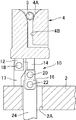
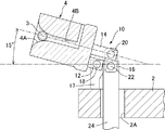
図2〜4は、図1に示すガラス塊の製造装置1における成形型4の構成を示す鉛直断面図であり、それぞれ、成形型4が異なる角度に傾斜した状態を示している。図2は、図1に示すガラス塊の製造装置1における直立した状態の成形型4を示す鉛直断面図である。図3は、直立状態からターンテーブル2の径方向外方に向けて傾斜している途中の状態の成形型4を示す鉛直断面図である。図4は、直立状態からターンテーブル2の径方向外方に向けて傾斜し、ガラス塊3が排出される直前の状態の成形型4を示す鉛直断面図である。これらの図に示すように、成形型4には、上方に向かって開口する凹部(内部空間)4Aが形成されており、この凹部4Aは上方に向かって拡張しており、すなわち、ほぼ逆円錐形を呈している。また、成形型4には浮上ガス通路4Bが形成されている。浮上ガス通路4Bの一端は側面に開口し、他端は凹部4Aの下端部に開口している。浮上ガス通路4Bの側面に開口する端部には、不図示の不活性ガスを供給するガス供給装置とガス供給装置から延びるガス供給管が接続されている。凹部4A内には浮上ガス通路4Bを介して供給された窒素ガスなどの不活性ガスが吹き出される。
2 to 4 are vertical cross-sectional views showing the configuration of the
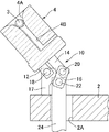
また、成形型4の下部には、成形型4を横方向に向けて傾斜させる成形型傾斜機構10が設けられている。成形型傾斜機構10は、成形型4の下面のターンテーブル2の径方向外側の部位に立設された第1傾斜機構部材12と、成形型4の下面の中心に立設された第2傾斜機構部材14と、第2傾斜機構部材14の下端に連結された第3傾斜機構部材16と、ターンテーブル2の上面に立設され、かつ、第1傾斜機構部材12の下端に連結された第4傾斜機構部材17と、第3傾斜機構部材16の下端部に連結された突き上げ棒24と、ガラス塊取出し位置のターンテーブル2の下方に設けられ、突き上げ棒24を駆動する傾斜機構駆動装置(図示せず)と、を備える。
A molding
第1傾斜機構部材12は、成形型4の下面に対して垂直に下方に向かって延びている。第1傾斜機構部材12の下端部は、ターンテーブル2の略周方向に延びる第1のピン18を介して、ターンテーブル2の径方向の鉛直平面内で回動可能に第4傾斜機構部材17に連結されている。
The first
第2傾斜機構部材14の下端部は、ターンテーブル2の略周方向に延びる第2のピン20を介して、ターンテーブル2の径方向の鉛直平面内で回動可能に第3傾斜機構部材16の上端部に接続されている。なお、第2傾斜機構部材14は、第1傾斜機構部材12よりも長尺な部材からなる。
The lower end portion of the second
第3傾斜機構部材16の下端部は、ターンテーブル2の略周方向に延びる第3のピン22を介して、ターンテーブル2の径方向の鉛直平面内で回動可能に傾斜機構駆動装置の突き上げ棒24の上端部に接続されている。
The lower end portion of the third
傾斜機構駆動装置は、ターンテーブル2の下方に設けられており、突き上げ棒24を鉛直方向に進退可能な装置である。突き上げ棒24は、ターンテーブル2に形成された開口2Aを挿通している。
The tilt mechanism driving device is a device that is provided below the
成形型傾斜機構10による成形型4の傾斜動作は具体的には以下のようにして行われる。
上述の通り、ガラス塊取出し位置Bまで移送された成形型4は、図2に示すように直立した状態となっている。ガラス塊取出し位置Bまで成形型4が移送されると、ターンテーブル2の回転停止中に、傾斜機構駆動装置により突き上げ棒24が鉛直上方に押し上げられる。突き上げ棒24が鉛直上方に押し上げられることにより、第3のピン22を介して第3傾斜機構部材16の下端部に上向きの力が付与される。このように第3傾斜機構部材16に付与された上向きの力は、第2傾斜機構部材14に伝達され、成形型4の中央に作用する。そして、成形型4は、下面に立設された第1傾斜機構部材12が第1のピン18を介して、ターンテーブル2の上面に立設された第4傾斜機構部材17の上端部に回転可能に接続されているため、第1のピン18を中心にターンテーブル2の外側に向かって移動するように回転する。なお、この際、第2傾斜機構部材14が成形型4とともに回転するため、第2のピン20は第1のピン18を中心とした円弧軌道を移動し、図3に示すように、第3傾斜機構部材16は下端を中心にターンテーブル2の中心に向かって傾斜する。このようにして、図4に示すように、成形型4の凹部4Aのターンテーブル2の径方向外側の面が、開口端部が底側端部よりも低くなるような角度まで成形型4を傾斜させる。
Specifically, the tilting operation of the
As described above, the
ガラス塊3の取出し時の成形型4の傾斜角度は、ガラス塊3の重量、成形型4の凹部4Aの側面の角度等に基づき、適宜設定すればよい。例えば、本実施形態では、図4に示すように、水平面に対して15°まで傾斜させている。
What is necessary is just to set suitably the inclination angle of the shaping | molding die 4 at the time of taking out the
なお、本実施形態では、成形型傾斜機構10を、第1傾斜機構部材12と、第2傾斜機構部材14と、第3傾斜機構部材16と、傾斜機構駆動装置とにより構成した場合について説明したが、成形型4を傾斜させる構成はこれに限られない。成形型傾斜機構は、トレイに向けて成形型の上端側を傾斜させることができればよい。
In the present embodiment, the case where the
また、本実施形態のガラス塊の製造装置は、成形型をターンテーブル2により間歇的に移送する構成となっているが、これに限らず、成形型を移送することなくガラス塊を製造する装置に本発明を適用することも可能である。
Further, the glass lump manufacturing apparatus of the present embodiment is configured to intermittently transfer the molding die by the
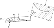
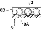
図5〜図7は、図1のガラス塊の製造装置における成形型4及びトレイ8を示す。図5は、図1のガラス塊の製造装置における成形型4及びトレイ8の上面図、図6は、図5におけるVI−VI断面図、図7は、図5におけるVII−VII断面図である。なお、これらの図では、成形型4は傾斜した状態で示している。図6に示すように、トレイ8は成形型4の側が上方に位置するように傾斜した状態で設けられている。トレイ8は矩形状であり、周縁部に上方に向かって立ち上がる側壁8Bが形成されるとともに、内側底面には複数の谷部8Aが傾斜方向に向かって延びるように所定の間隔をあけて平行に形成されている。トレイ8は、軟性が高い材料により形成されていることが好ましい。成形型4からトレイ8への移送において、ガラス塊3に付与されるダメージが低減されるためである。また、軟性に加えて、耐熱性が高い材料により形成されていることがより好ましい。このような軟性が高く、熱耐性が高い材料としては、PTFE(Polytetrafluoroethylene)、PFA(Perfluoroalkoxy)、FEP(Fluorinated Ethylene Propylene)、PCTFE(Polychlorotrifluoroethylene)、ETFE(Ethylenetetrafluoroethylene)、ECTFE(Ethylene Chlorotrifluoroethylene)等のフッ素樹脂が挙げられる。この中でも、ロックウェル硬さがR50未満の材料が好ましく、PTFEが好適である。
FIGS. 5-7 shows the shaping | molding die 4 and the
また、必ずしもトレイ8の全体を軟性が高く、かつ、熱耐性の高い材料により形成する必要はない。例えば、基材としてメタル等の硬質材を用い、少なくともガラス塊と接触する部分(内側底面及び側壁内側面)が、ロックウェル硬さがR50未満の材料で形成されていればよい。なお、トレイ8は、例えば、ロボットアームなどの移動装置により、傾斜方向と直交する方向に水平移動可能に支持されている。
Further, it is not always necessary to form the
以下、本実施形態のガラス塊の製造装置1によるガラス塊3の製造方法を説明する。なお、以下の説明では一の成形型に着目してガラス塊の製造方法を説明する。
再度、図1を参照し、熔融ガラス供給位置Aにおいて、成形型4が直立した状態で、熔融ガラス供給装置6により成形型4内に熔融ガラス3を供給する。熔融ガラス供給装置6おける熔融ガラスの供給は、例えば、既知の降下切断法を利用することにより行うことができる。
Hereinafter, the manufacturing method of the
Referring again to FIG. 1, at the molten glass supply position A, the
次に、ターンテーブル2を間歇的に回転させながら、図2に示すように、上方に向かって拡張して開口する凹部(内部空間)4Aを有する成形型4を用い、ガラス塊3は凹部4A内で既知の浮上成形によりほぼ球形状に成形される(成形工程)。すなわち、図2に示すように、浮上成形は、不図示のガス供給装置により、成形型4内に浮上ガス通路4Bを通じて上方に向けて凹部4A内にガスを噴出することにより行われる。これにより、凹部4A内の熔融ガラス3は上方に向かう風圧を受けながら成形されるととともに徐冷されて、ほぼ球形状のガラス塊3となる。なお、本実施形態では、ガラス塊3をできるだけ完全な球形状に成型するために、成形型4が直立した状態において凹部4Aの形状が平面視で円形、断面視で上方に向かって拡張する形状としている。また、この成形型4内において溶融ガラスをほぼ球形状のガラス塊に成形する工程は、図2に示すように成形型4が直立した状態で行われる。
Next, while rotating the
成形型4がガラス塊取出し位置Bまで移送されると、図3、図4に示すように、成形型4は成形型傾斜機構10によりターンテーブル2の径方向外方に向けて傾斜される。図5、図6に示すように、成形型4が傾斜されることにより、ガラス塊3は成形型の凹部4Aから成形型4の下方に配置されたトレイ(収納容器)8に移送される(移送工程)。
When the
ターンテーブル2が間歇的に回転することにより、ガラス塊取出し位置Bに成形型4が移送され、移送された成形型4からガラス塊3が、順次、トレイ8の上方端部近傍へと移送される。
When the
図5、図6に示すように、トレイ8は傾斜するとともに傾斜方向に延びる谷部8Aが形成されているため、トレイ8の上方端部に移送されたガラス塊3は谷部8Aに案内されながら、自重によりトレイ8の下方側に向かって転がりながら移動する。そして、一の谷部8Aに所定の個数(例えば、5個)のガラス塊3が移送されるごとに、移動装置によりトレイ8を谷部8Aの間隔に相当する距離、傾斜方向と直交する方向に水平移動させる(すなわち、隣接する谷部8Aに成形型4からガラス塊3が移送されるような位置までトレイ8を移動する)。このようにして、成形型4から移送されたガラス塊3は、各谷部8Aに所定の個数ずつ並んだ状態に配列される。
As shown in FIGS. 5 and 6, since the
以上、説明したように、本実施形態では、成形型傾斜機構10により成形型4を傾斜させて成形型4の凹部4Aから排出させることにより、成形されたガラス塊3をトレイ8上に移送している。このため、ガラス塊3の重量によらず、確実に成形型4からガラス塊3を移送することができる。
As described above, in the present embodiment, the molded
本実施形態のガラス塊の製造方法は、摩耗度が400以上のガラス材料からなるガラス塊を製造するのに好適である。摩耗度が400以上のガラス材料は、衝撃等により傷がつきやすい。従来、ガラス塊の成形型からの取出し方法として、先端部に吸引治具を備えた搬送機構により、吸引治具によりガラス塊を吸着し、成形型から取り出す方法が用いられることがあった。しかしながら、摩耗度400以上のガラス材料からなるガラス塊を吸引治具により吸着すると、ガラス塊の表面にひびや傷等の損傷が生じてしまうという問題があった。これに対して、本実施形態では、ガラス塊に治具等を接触させることなくガラス塊を移送することができるため、傷がつきやすいガラス材料からなるガラス塊3であっても、損傷することなく移送できる。
The method for producing a glass lump according to the present embodiment is suitable for producing a glass lump made of a glass material having a wear degree of 400 or more. A glass material having an abrasion degree of 400 or more is easily damaged by impact or the like. Conventionally, as a method for taking out a glass lump from a mold, there has been used a method in which a glass lump is adsorbed by a suction jig and taken out from the mold by a transport mechanism having a suction jig at the tip. However, when a glass lump made of a glass material having an abrasion degree of 400 or more is adsorbed by a suction jig, there is a problem that damage such as cracks or scratches occurs on the surface of the glass lump. On the other hand, in this embodiment, since the glass lump can be transferred without bringing a jig or the like into contact with the glass lump, even the
摩耗度400以上のガラス材料としては、例えば、フツリン酸塩ガラスが挙げられる。フツリン酸塩ガラスは、フッ素を含有するガラスであり、衝撃等により傷がつきやすいという特性を有する。当然のことながら、フッ素以外に銅等を含有した赤外線吸収ガラス等も本発明のフツリン酸塩ガラスに含まれる。 Examples of the glass material having an abrasion degree of 400 or more include fluorophosphate glass. Fluorophosphate glass is a glass containing fluorine and has a characteristic that it is easily damaged by impact or the like. As a matter of course, an infrared absorbing glass containing copper or the like in addition to fluorine is also included in the fluorophosphate glass of the present invention.
さらに、本実施形態では、トレイ8の少なくともガラス塊3と接触する部分を軟性が高い材料、特に、ロックウェル硬さがR50未満の材料により形成したため、ガラス塊3が成形型4からトレイ8上に移送された際に、ガラス塊3に傷が付くことを防止できる。このことは、ガラス塊3を摩耗度が400以上のガラス材料により形成する場合に特に好適である。
Further, in this embodiment, at least a portion of the
次に、本発明の第2実施形態のガラス塊の製造装置について説明する。本実施形態のガラス塊の製造装置は、成形型とトレイとの間に長尺な搬送部材が設けられ、この搬送部材を介して成形型からトレイにガラス塊が搬送される点が異なり、その他の構成は第1実施形態と同様である。なお、本実施形態において、第1実施形態と同様の構成については、同じ符号を付して詳細な説明を省略する。 Next, a glass lump manufacturing apparatus according to a second embodiment of the present invention will be described. The glass lump manufacturing apparatus of the present embodiment is different in that a long conveying member is provided between the mold and the tray, and the glass lump is conveyed from the mold to the tray via this conveying member. The configuration is the same as that of the first embodiment. In the present embodiment, the same components as those in the first embodiment are denoted by the same reference numerals, and detailed description thereof is omitted.
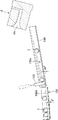
図8〜図10は、第2実施形態のガラス塊の製造装置における成形型4、搬送部材130、及びトレイ108を示す図である。図8は、第2実施形態のガラス塊の製造装置における成形型4、搬送部材130、及びトレイ108を示す上面図、図9は、図8におけるIX−IX断面図であり、図10は、図8におけるX-X断面図である。なお、図中、成形型4は傾斜した状態で示されている。図8及び図9に示すように、第2実施形態のガラス塊の製造装置では、成形型4の下方にターンテーブルの径方向に延びるように搬送部材130が設けられている。搬送部材130は、成形型4側の端部が、トレイ108側の端部よりも高くなるように傾斜している。搬送部材130の下端は、トレイ108の上方端部近傍まで伸びている。図10に示すように、搬送部材130の上面には、例えば、断面逆三角形状の凹部130aが長手方向に延びるように、幅方向中央に形成されている。
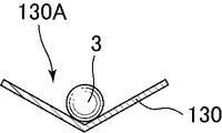
8-10 is a figure which shows the shaping | molding die 4, the
図8、図9に示すように、搬送部材130の下方端部には、ストッパー132が設けられている。ストッパー132は、搬送部材130上に当接するとともに凹部130Aを横方向に跨ぐように配置され、ガラス塊3を搬送部材130上にせき止めることができる下方位置と、搬送部材130と上下方向に離間して間に、ガラス塊3の直径よりも大きな隙間が形成された上方位置との間を移動可能である。
As shown in FIGS. 8 and 9, a
搬送部材130及びストッパー132は、第1実施形態のトレイ8と同様に、軟性が高い材料により形成されていることが好ましい。軟性に加えて、耐熱性が高い材料により形成されていることがより好ましい。このような軟性が高く、耐熱性が高い材料としては、PTFE、PFA等のフッ素樹脂が挙げられる。中でも、ロックウェル硬さがR50未満の材料であるPTFEが好適である。なお、基材としてメタル等の硬質材を用い、少なくともガラス塊と接触する部分が、ロックウェル硬さがR50未満の軟性が高い材料により形成してもよい点は第1実施形態のトレイ8と同様である。
The
図9に示すように、トレイ108は搬送部材130の側が上方に位置するように傾斜するように設けられている。なお、トレイ108の水平方向に対する傾斜角度は、搬送部材130の水平方向に対する傾斜角度よりも小さいことが好ましい。成形型4からトレイ108への移送時におけるガラス塊3へのダメージ付与がより低減されるためである。また、トレイ108は、第1実施形態と同様に、底部に複数の谷部108Aが平行に所定の間隔をあけて形成されている。なお、第2実施形態のトレイ108は、第1実施形態のトレイ8と比較して、搬送部材130側の縁には側壁が設けられていないが、その他の構成は同じである。
As shown in FIG. 9, the
本実施形態のガラス塊の製造方法は、ガラス塊を成形型からトレイに移送する移送工程のみが異なり、熔融ガラス供給工程及び成形工程については第1実施形態と同様に行われる。以下、第2実施形態のガラス塊の製造方法における移送工程を説明する。 The glass lump manufacturing method of the present embodiment is different only in the transfer process of transferring the glass lump from the mold to the tray, and the molten glass supply process and the molding process are performed in the same manner as in the first embodiment. Hereinafter, the transfer process in the manufacturing method of the glass lump of 2nd Embodiment is demonstrated.
第2の実施形態においては、図8、図9に示すように、成形型4とトレイ(収納容器)108との間に、ガラス塊3を搬送する搬送部材130が設けられている。搬送部材130は、少なくともガラス塊3と接触する部分が、ロックウェル硬さがR50未満の材料で形成されている。
In the second embodiment, as shown in FIGS. 8 and 9, a conveying
第1実施形態において説明したように、ガラス塊取出し位置まで移送された成形型4は成形型傾斜機構により搬送部材130に向けて傾斜される。図8、図9に示すように、成形型4が傾斜されることにより、成形型4の凹部4A内に位置する成形後のガラス塊3は、自重により凹部4A内を転がり、成形型4の下方に位置する搬送部材130の上方端部へ移送される。搬送部材130の上方端部に移送されたガラス塊3は凹部130Aに案内されながら、自重によりトレイ108の下方側に向かって転がって移動する。そして、搬送部材130の下端端部から、さらに、搬送部材130の下端端部の下方に位置するトレイ108の上方端部へ移送される。トレイ108の上方端部に移送されたガラス塊は谷部108Aに案内されながら、自重によりトレイ108の下方側に向かって転がって移動する。
As described in the first embodiment, the
図8、図9に示すように、ストッパー132は、一のガラス塊3が搬送部材130の上方端部から下方端部に移動する前に、下方位置へと移動させることができる。ストッパー132を下方位置へ移動させることにより、一のガラス塊3は、いったんせき止められ、停止する。その後、ストッパー132を上方位置に移動させることにより、一のガラス塊3はトレイ8に移送される。このストッパー132の動作により、トレイ108への移送時および移送後におけるガラス塊3のスピードが低下するため、ガラス塊3へのダメージ付与が低減される。ストッパー132の上方位置への移動は、後続の他のガラス塊3が成形型4から搬送部材130に移送される前に行うのが好ましい。一のガラス塊と他のガラス塊との衝突によるガラス塊3同士に付与されるダメージが避けられるためである。
As shown in FIGS. 8 and 9, the
他のストッパー132の適用例については、以下が挙げられる。図8に示すように、トレイ108の一の谷部108Aに所定の個数(例えば、5個)のガラス塊3が移送されると、ストッパー132を下方位置へと移動する。そして、移動装置によりトレイ108を谷部108Aの間隔に相当する距離、傾斜方向と直交する方向に水平移動する(すなわち、隣接する谷部108Aに成形型4からガラス塊3が移送されるような位置までトレイ108を移動する)。トレイ108を移動する間に、成形型4からガラス塊3が搬送部材130へと移送された場合には、ガラス塊3は搬送部材130の凹部130Aを転がるが、下端近傍でストッパー132にせき止められる。そして、トレイ108の水平移動が完了すると、ストッパー132が上方位置まで上昇する。これにより、ストッパー132によりせき止められていたガラス塊3は上述した谷部108Aに隣接する谷部108Aへと移送される。このようにして、成形型4から移送されたガラス塊3は、各谷部108Aに所定の個数ずつ並んだ状態に配列される。
Examples of other application examples of the
以上説明したように、第2実施形態のガラス塊の製造装置によれば、第1実施形態のガラス製造装置により得られる作用効果に加えて、以下の作用効果が得られる。
第2実施形態によれば、成形型4とトレイ108との間に搬送部材130を配置し、搬送部材130の下端に上下に移動可能なストッパー132を設けている。搬送部材130を移動するガラス塊3は、トレイ108に移送される前に、ストッパー132によりいったん停止させることができる。これにより、搬送部材130からトレイ108への移送時および移送後のガラス塊3のスピードが低下するため、ガラス塊3へのダメージ付与が低減される。また、トレイ108の移動中にストッパー132により搬送部材130上にガラス塊3をせき止めることができる。これにより、ガラス塊3を所望の位置に確実に配列することができる。
As described above, according to the glass lump manufacturing apparatus of the second embodiment, the following functions and effects can be obtained in addition to the functions and effects obtained by the glass manufacturing apparatus of the first embodiment.
According to the second embodiment, the conveying
以下、上記各実施形態のガラス塊の製造装置により製造したガラス塊を用いてレンズ等の光学素子を製造する方法を説明する。以下の説明では、光学素子を製造する方法として、モールドプレス成形法を用いた場合について説明するが、当然、その他の方法を用いることも可能である。モールドプレス成形法では、対向する一対の上型及び下型を含む成形型によりプリフォーム(ガラス塊)をプレス成形して光学素子を製造する。 Hereinafter, a method of manufacturing an optical element such as a lens using the glass block manufactured by the glass block manufacturing apparatus of each of the embodiments will be described. In the following description, a case where a mold press molding method is used as a method for manufacturing an optical element will be described, but other methods can naturally be used. In the mold press molding method, an optical element is manufactured by press-molding a preform (glass lump) with a mold including a pair of upper and lower molds facing each other.
まず、成形型の下型上にガラス塊を配置する。次に、成形型とともにガラス塊を、例えば、粘度が105〜109Pa・s程度となるまで加熱する。そして、上型及び下型にプレス荷重を加え、ガラス塊をプレス成形する。 First, a glass lump is placed on the lower mold of the mold. Next, the glass lump is heated together with the mold until, for example, the viscosity is about 10 5 to 10 9 Pa · s. Then, a press load is applied to the upper die and the lower die, and the glass lump is press-molded.
なお、予めガラス塊を粘度が105〜109Pa・s程度となるまで加熱しておくとともに、成形型を、ガラス塊の粘度が109〜1013Pa・s程度となる温度まで加熱しておき、ガラス塊を下型上に配置した後に、直ちにプレス成形してもよい。 In addition, while heating a glass lump beforehand until a viscosity will be about 10 < 5 > -10 < 9 > Pa * s, a shaping | molding die is heated to the temperature from which the viscosity of a glass lump will be about 10 < 9 > -10 < 13 > Pa * s. In addition, after placing the glass block on the lower mold, it may be press-molded immediately.
いずれの場合であっても、プレス成形終了後に成形型の冷却を開始し、上型と下型の成形面とガラス塊の密着を維持しながら、ガラス塊が1013Pa・s程度の粘度となるまで温度を低下させた後に、上型を上昇させてプレス荷重を解除し、成形体であるレンズの取出しを行う。 In any case, the cooling of the mold is started after the press molding is completed, and the glass lump has a viscosity of about 10 13 Pa · s while maintaining the adhesion between the molding surfaces of the upper mold and the lower mold and the glass lump. After lowering the temperature until the upper limit is reached, the upper die is raised to release the press load, and the lens as a molded body is taken out.
以下、図面を参照しながら、本発明を総括する。
第1実施形態のガラス塊の製造方法は、図2〜図4に示すように、上方に向かって拡張して開口する凹部4Aを有する成形型4を用い、凹部4A内で浮上成形によりほぼ球形にガラス塊3を成形する成形工程と、成形型4を傾斜させて、成形型4の凹部4Aからガラス塊3を成形型4の下方に配置されたトレイ8に移送する移送工程と、を備える。
The present invention will be summarized below with reference to the drawings.
As shown in FIGS. 2 to 4, the glass lump manufacturing method of the first embodiment uses a
また、第1実施形態のガラス塊の製造装置は、図2〜図4に示すように、上方に向かって拡張して開口する凹部4Aを有し、凹部4A内で浮上成形によりほぼ球形にガラス塊3を成形する成形型4と、成形型4の凹部4Aからガラス塊3をトレイ8に移送するように成形型4を傾斜させる成形型傾斜機構10と、を備える。
Moreover, as shown in FIGS. 2 to 4, the glass lump manufacturing apparatus of the first embodiment has a
1 ガラス塊の製造装置
2 ターンテーブル
3 ガラス塊(熔融ガラス)
4 成形型
6 熔融ガラス供給装置
8、108 トレイ
10 成形型傾斜機構
12 第1傾斜機構部材
14 第2傾斜機構部材
16 第3傾斜機構部材
17 第4傾斜機構部材
18 第1のピン
20 第2のピン
22 第3のピン
24 突き上げ棒
130 搬送部材
1 Glass
4 Mold 6 Molten
Claims (6)
前記成形型を傾斜させて、前記成形型の内部空間から前記ガラス塊を前記成形型の下方に配置された収納容器に移送する移送工程と、を備える、ガラス塊の製造方法。 A molding step of forming a glass lump into a substantially spherical shape by floating molding in the internal space using a mold having an internal space that expands upward and opens,
A method of manufacturing a glass lump, comprising a step of inclining the mold and transferring the glass lump from an internal space of the mold to a storage container disposed below the mold.
前記収納容器及び前記搬送部材は、少なくともガラス塊と接触する部分が、ロックウェル硬さがR50未満の材料で形成されている、請求項1〜3の何れか1項に記載のガラス塊の製造方法。 A conveying member for conveying the glass block is provided between the mold and the storage container,
The said container and the said conveyance member are the manufacture of the glass lump of any one of Claims 1-3 in which the part which contacts a glass lump is formed with the material whose Rockwell hardness is less than R50. Method.
前記成形型の前記内部空間から前記ガラス塊を収納容器に移送するように前記成形型を傾斜させる成形型傾斜機構と、を備える、ガラス塊の製造装置。 A mold that has an internal space that extends upward and opens, and that forms a glass lump into a substantially spherical shape by levitation molding in the internal space;
An apparatus for manufacturing a glass lump, comprising: a mold tilt mechanism that tilts the mold so as to transfer the glass lump from the internal space of the mold to a storage container.
Priority Applications (1)
| Application Number | Priority Date | Filing Date | Title |
|---|---|---|---|
| JP2014266389A JP2016124733A (en) | 2014-12-26 | 2014-12-26 | Production method of glass gob, and production apparatus of glass gob |
Applications Claiming Priority (1)
| Application Number | Priority Date | Filing Date | Title |
|---|---|---|---|
| JP2014266389A JP2016124733A (en) | 2014-12-26 | 2014-12-26 | Production method of glass gob, and production apparatus of glass gob |
Publications (2)
| Publication Number | Publication Date |
|---|---|
| JP2016124733A true JP2016124733A (en) | 2016-07-11 |
| JP2016124733A5 JP2016124733A5 (en) | 2018-02-15 |
Family
ID=56358791
Family Applications (1)
| Application Number | Title | Priority Date | Filing Date |
|---|---|---|---|
| JP2014266389A Pending JP2016124733A (en) | 2014-12-26 | 2014-12-26 | Production method of glass gob, and production apparatus of glass gob |
Country Status (1)
| Country | Link |
|---|---|
| JP (1) | JP2016124733A (en) |
Cited By (1)
| Publication number | Priority date | Publication date | Assignee | Title |
|---|---|---|---|---|
| WO2019146000A1 (en) * | 2018-01-23 | 2019-08-01 | 日本電気硝子株式会社 | Airflow levitation type glass body production device and airflow levitation type glass body production method |
Citations (12)
| Publication number | Priority date | Publication date | Assignee | Title |
|---|---|---|---|---|
| JP2000007360A (en) * | 1998-06-25 | 2000-01-11 | Canon Inc | Production of glass element |
| JP2001010827A (en) * | 1999-06-23 | 2001-01-16 | Fuji Photo Optical Co Ltd | Apparatus and method for producing glass gob for forming optical element |
| JP2007230831A (en) * | 2006-03-02 | 2007-09-13 | Hoya Corp | Method for manufacturing glass molding and method for manufacturing optical element |
| JP2007269614A (en) * | 2006-03-31 | 2007-10-18 | Hoya Corp | Glass base material for mold press and method of manufacturing glass optical device |
| JP2007297221A (en) * | 2006-04-27 | 2007-11-15 | Hoya Corp | Method for manufacturing glass molding and method for manufacturing optical element |
| JP2008137877A (en) * | 2006-12-05 | 2008-06-19 | Hoya Corp | Optical glass and optical element |
| JP2009242177A (en) * | 2008-03-31 | 2009-10-22 | Ohara Inc | Glass gob production method and glass gob production device |
| JP2009256167A (en) * | 2008-03-28 | 2009-11-05 | Hoya Corp | Fluorophosphate glass, glass material for press-molding, optical element blank, optical element and methods for manufacturing the same |
| JP2009286670A (en) * | 2008-05-30 | 2009-12-10 | Hoya Corp | Optical glass, glass raw material for press molding, optical element blank, optical element, and method for manufacturing the same |
| JP2010228984A (en) * | 2009-03-27 | 2010-10-14 | Nippon Electric Glass Co Ltd | Airflow levitation type production apparatus for glass body and airflow levitation type production method for glass body |
| WO2014014060A1 (en) * | 2012-07-18 | 2014-01-23 | Hoya株式会社 | Optical glass, glass material for press molding, optical element, method for producing glass material for press molding, and method for producing optical element |
| JP2014028748A (en) * | 2012-06-29 | 2014-02-13 | Hoya Corp | Glass gob manufacturing apparatus, glass gob manufacturing method, method for manufacturing glass formed article, and method for manufacturing optical element |
-
2014
- 2014-12-26 JP JP2014266389A patent/JP2016124733A/en active Pending
Patent Citations (12)
| Publication number | Priority date | Publication date | Assignee | Title |
|---|---|---|---|---|
| JP2000007360A (en) * | 1998-06-25 | 2000-01-11 | Canon Inc | Production of glass element |
| JP2001010827A (en) * | 1999-06-23 | 2001-01-16 | Fuji Photo Optical Co Ltd | Apparatus and method for producing glass gob for forming optical element |
| JP2007230831A (en) * | 2006-03-02 | 2007-09-13 | Hoya Corp | Method for manufacturing glass molding and method for manufacturing optical element |
| JP2007269614A (en) * | 2006-03-31 | 2007-10-18 | Hoya Corp | Glass base material for mold press and method of manufacturing glass optical device |
| JP2007297221A (en) * | 2006-04-27 | 2007-11-15 | Hoya Corp | Method for manufacturing glass molding and method for manufacturing optical element |
| JP2008137877A (en) * | 2006-12-05 | 2008-06-19 | Hoya Corp | Optical glass and optical element |
| JP2009256167A (en) * | 2008-03-28 | 2009-11-05 | Hoya Corp | Fluorophosphate glass, glass material for press-molding, optical element blank, optical element and methods for manufacturing the same |
| JP2009242177A (en) * | 2008-03-31 | 2009-10-22 | Ohara Inc | Glass gob production method and glass gob production device |
| JP2009286670A (en) * | 2008-05-30 | 2009-12-10 | Hoya Corp | Optical glass, glass raw material for press molding, optical element blank, optical element, and method for manufacturing the same |
| JP2010228984A (en) * | 2009-03-27 | 2010-10-14 | Nippon Electric Glass Co Ltd | Airflow levitation type production apparatus for glass body and airflow levitation type production method for glass body |
| JP2014028748A (en) * | 2012-06-29 | 2014-02-13 | Hoya Corp | Glass gob manufacturing apparatus, glass gob manufacturing method, method for manufacturing glass formed article, and method for manufacturing optical element |
| WO2014014060A1 (en) * | 2012-07-18 | 2014-01-23 | Hoya株式会社 | Optical glass, glass material for press molding, optical element, method for producing glass material for press molding, and method for producing optical element |
Cited By (2)
| Publication number | Priority date | Publication date | Assignee | Title |
|---|---|---|---|---|
| WO2019146000A1 (en) * | 2018-01-23 | 2019-08-01 | 日本電気硝子株式会社 | Airflow levitation type glass body production device and airflow levitation type glass body production method |
| CN111655634A (en) * | 2018-01-23 | 2020-09-11 | 日本电气硝子株式会社 | Air flow suspension type glass body manufacturing device and air flow suspension type glass body manufacturing method |
Similar Documents
| Publication | Publication Date | Title |
|---|---|---|
| CN101486085A (en) | Flat cut type plate-casting machine | |
| TW201920020A (en) | Systems and methods for processing a glass ribbon | |
| JP4918182B2 (en) | Manufacturing method and manufacturing apparatus for glass molded body, and manufacturing method for optical element | |
| JP2016124733A (en) | Production method of glass gob, and production apparatus of glass gob | |
| JP5200074B2 (en) | Mold press molding apparatus and optical element manufacturing method | |
| JPH10338530A (en) | Production of softened glass and floating holder | |
| JP4346624B2 (en) | Method for producing glass molded body and method for producing optical element | |
| JP2009179486A (en) | Method for producing hot-molded article, method for producing preform for precision press molding, and method for producing optical element | |
| JP2009007223A (en) | Method and apparatus for producing glass formed article | |
| CN100347108C (en) | Moulding forming device and method for making optical element | |
| CN101258109A (en) | Apparatus for molding optical element | |
| JP2007099529A (en) | Preform for precision press forming, its producing method and method for producing optical element | |
| JP5345228B2 (en) | Manufacturing method of glass preform for precision press molding and manufacturing method of optical element | |
| JP3922756B2 (en) | Method and apparatus for press molding glass molded article | |
| JP2011153051A (en) | Forming method for glass formed product and apparatus for the same | |
| JP5121610B2 (en) | Optical element molding method and optical element molding material | |
| JP4680738B2 (en) | Mold press molding apparatus and optical element manufacturing method | |
| JP2016138037A (en) | Glass gob manufacturing method, glass gob manufacturing apparatus, optical element manufacturing method, and manufacturing method of lens blank for polishing | |
| JP6055714B2 (en) | Glass lump manufacturing method, glass lump manufacturing apparatus, and glass molded product manufacturing method | |
| KR101979580B1 (en) | Automatic aligning insert device | |
| JP2014001088A (en) | Glass lump molding device, method for manufacturing glass lump, method for manufacturing glass optical element, and method for casting glass lump in glass lump molding device | |
| JP2010105871A (en) | Method and apparatus for manufacturing optical device | |
| JP4877743B2 (en) | Method for producing glass molded body and method for producing optical element | |
| CN100581429C (en) | Glass for sealing and its manufacturing method | |
| JP2021523086A (en) | Equipment and methods for processing glass sheets |
Legal Events
| Date | Code | Title | Description |
|---|---|---|---|
| RD04 | Notification of resignation of power of attorney |
Free format text: JAPANESE INTERMEDIATE CODE: A7424 Effective date: 20170426 |
|
| A521 | Request for written amendment filed |
Free format text: JAPANESE INTERMEDIATE CODE: A523 Effective date: 20171225 |
|
| A621 | Written request for application examination |
Free format text: JAPANESE INTERMEDIATE CODE: A621 Effective date: 20171225 |
|
| A977 | Report on retrieval |
Free format text: JAPANESE INTERMEDIATE CODE: A971007 Effective date: 20180925 |
|
| A131 | Notification of reasons for refusal |
Free format text: JAPANESE INTERMEDIATE CODE: A131 Effective date: 20181017 |
|
| A601 | Written request for extension of time |
Free format text: JAPANESE INTERMEDIATE CODE: A601 Effective date: 20181217 |
|
| A02 | Decision of refusal |
Free format text: JAPANESE INTERMEDIATE CODE: A02 Effective date: 20190508 |