JP2016123795A - Medical device - Google Patents

Medical device Download PDF

Info

Publication number
JP2016123795A
JP2016123795A JP2015002045A JP2015002045A JP2016123795A JP 2016123795 A JP2016123795 A JP 2016123795A JP 2015002045 A JP2015002045 A JP 2015002045A JP 2015002045 A JP2015002045 A JP 2015002045A JP 2016123795 A JP2016123795 A JP 2016123795A
Authority
JP
Japan
Prior art keywords
lumen
image
shaft
guide wire
medical device
Prior art date
Legal status (The legal status is an assumption and is not a legal conclusion. Google has not performed a legal analysis and makes no representation as to the accuracy of the status listed.)
Pending
Application number
JP2015002045A
Other languages
Japanese (ja)
Inventor
泰徳 山下
Yasunori Yamashita
泰徳 山下
丸山 智司
Tomoji Maruyama
智司 丸山
Current Assignee (The listed assignees may be inaccurate. Google has not performed a legal analysis and makes no representation or warranty as to the accuracy of the list.)
Terumo Corp
Original Assignee
Terumo Corp
Priority date (The priority date is an assumption and is not a legal conclusion. Google has not performed a legal analysis and makes no representation as to the accuracy of the date listed.)
Filing date
Publication date
Application filed by Terumo Corp filed Critical Terumo Corp
Priority to JP2015002045A priority Critical patent/JP2016123795A/en
Publication of JP2016123795A publication Critical patent/JP2016123795A/en
Pending legal-status Critical Current

Links

Images

Abstract

PROBLEM TO BE SOLVED: To provide a medical device capable of acquiring image information that enables efficient execution of priming.SOLUTION: A medical device 1 having an imaging function comprises: a shaft body part 22 in which an imaging lumen 25 and a guide wire lumen 26 are formed; a shaft tip part 21 in which a common lumen 27 communicating with the imaging lumen 25 and the guide wire lumen 26 is formed; a hub 5 to which a tip part of the shaft body part 22 is connected, and the imaging lumen 25 and the guide wire lumen 26 are open; a drive shaft 42 movable inside the imaging lumen 25 in a rotation direction and an axial direction; a vibrator unit 41 which is fixed to a tip of the drive shaft 42 and is movable inside the common lumen 27; and a restriction member 8 which is arranged on the base end side from the vibrator unit 41 inside the imaging lumen 25, and restricts movement of a liquid body while allowing a rotational motion and a motion in the axial direction of the drive shaft 42.SELECTED DRAWING: Figure 1

Description

本発明は、生体管腔内に挿入されて画像情報を取得可能な医療用デバイスに関する。   The present invention relates to a medical device that can be inserted into a living body lumen to acquire image information.

従来から、撮像機能を有する信号送受信部を内蔵したカテーテルを心臓の冠状動脈などの血管、胆管等の管腔内に挿入して、画像診断が行われている。例えば、特許文献1には、超音波を送受信するための振動子ユニットおよびこの振動子ユニットを回転させる駆動シャフトを備えるイメージングコアと、このイメージングコアを内蔵するとともに管腔内に挿入されるシャフト部を有する超音波カテーテルが記載されている。このような超音波カテーテルは、イメージングコアをシャフト部内で回転させて超音波を送信するとともに、同じイメージングコアにより生体組織で反射した信号を受信する。受信した信号に、増幅、検波等の処理を施すことで、管腔の断面画像を描出できる。   2. Description of the Related Art Conventionally, image diagnosis is performed by inserting a catheter incorporating a signal transmission / reception unit having an imaging function into a blood vessel such as a coronary artery of the heart or a lumen such as a bile duct. For example, Patent Document 1 discloses an imaging core that includes a transducer unit for transmitting and receiving ultrasonic waves and a drive shaft that rotates the transducer unit, and a shaft portion that incorporates the imaging core and is inserted into a lumen. An ultrasonic catheter is described. Such an ultrasonic catheter transmits an ultrasonic wave by rotating an imaging core within a shaft portion, and receives a signal reflected by a living tissue by the same imaging core. By performing processing such as amplification and detection on the received signal, a cross-sectional image of the lumen can be depicted.

このような超音波カテーテルにおいては、振動子ユニットと診断対象となる血管壁等との間に、信号伝搬物質が存在することが望ましい場合があり、シャフト部の内部を空気などの気体から生理食塩液等の液体へ置換するプライミング作業を行うことがある。   In such an ultrasonic catheter, it may be desirable for a signal propagation material to be present between the transducer unit and a blood vessel wall or the like to be diagnosed. A priming operation for substituting with a liquid such as a liquid may be performed.

特開2003−126092号公報JP 2003-126092 A

特許文献1に記載の超音波カテーテルは、振動子ユニットを回転駆動させる駆動シャフトが、柔軟性を付与するために内部が中空のコイル状に形成されている。このため、プライミングが完了してシースと駆動シャフトの間が生理食塩液等に置換されても、駆動シャフトの内部には気体が付着・残留しやすく、気体が残ったままとなる場合がある。また、駆動シャフトが中空のコイル状でなかったとしても、駆動シャフトが存在することで圧力損失が大きいため、気体が残らないようにプライミングすることが困難な場合がある。プライミングが不十分であると、気泡が振動子ユニットの表面に付着する可能性が高まり、信号の送受信に影響を及ぼし、望ましい画像を取得することが困難となる場合がある。   In the ultrasonic catheter described in Patent Document 1, a drive shaft that rotationally drives the transducer unit is formed in a hollow coil shape in order to provide flexibility. For this reason, even if the priming is completed and the space between the sheath and the drive shaft is replaced with physiological saline or the like, gas tends to adhere and remain inside the drive shaft, and the gas may remain. Even if the drive shaft is not in the form of a hollow coil, the presence of the drive shaft causes a large pressure loss, so it may be difficult to perform priming so that no gas remains. Insufficient priming increases the possibility of bubbles adhering to the surface of the transducer unit, affecting the transmission / reception of signals and making it difficult to obtain a desired image.

本発明は、上述した課題を解決するためになされたものであり、プライミングを効率よく行うことが可能となる画像情報を取得可能な医療用デバイスを提供することを目的とする。   SUMMARY An advantage of some aspects of the invention is that it provides a medical device that can acquire image information that enables efficient priming.

上記目的を達成する医療用デバイスは、生体管腔内に挿入して画像を取得するための医療用デバイスであって、画像を取得するための画像用ルーメンおよびガイドワイヤ用のガイドワイヤルーメンが形成されるシャフト本体部と、前記シャフト本体部の先端側に形成されて前記画像用ルーメンおよびガイドワイヤルーメンと連通して先端側で開口する共通ルーメンが形成されるシャフト先端部と、前記シャフト本体部の基端部が連結されて前記画像用ルーメンおよびガイドワイヤルーメンが開口するハブと、前記画像用ルーメン内で回転方向および軸線方向への移動が可能な駆動シャフトと、前記駆動シャフトの先端に固定されて画像情報を取得可能であり、前記駆動シャフトにより駆動されて前記共通ルーメンおよび画像用ルーメンの少なくとも共通ルーメン内を移動可能な撮像部と、前記画像用ルーメン内の前記撮像部よりも基端側に配置されて前記駆動シャフトの回転運動および軸線方向への運動を許容しつつ流体の移動を規制する規制部材と、を有する。   A medical device that achieves the above object is a medical device that is inserted into a living body lumen to acquire an image, and an image lumen for acquiring an image and a guide wire lumen for a guide wire are formed. A shaft main body portion, a shaft front end portion that is formed on the front end side of the shaft main body portion and that is connected to the image lumen and the guide wire lumen and is open on the front end side, and the shaft main body portion Fixed to the distal end of the drive shaft, a hub in which the image lumen and the guide wire lumen are opened by being connected to each other, a drive shaft capable of moving in the rotational direction and the axial direction within the image lumen, and Image information can be acquired and driven by the drive shaft to reduce the common lumen and the image lumen. Both of the imaging unit movable within the common lumen and the proximal end side of the imaging unit in the image lumen to allow the fluid to move while allowing the drive shaft to rotate and move in the axial direction. And a regulating member for regulating.

上記のように構成した医療用デバイスは、画像用ルーメン内の撮像部よりも基端側に、駆動シャフトの回転運動および軸線方向への運動を許容しつつ流体の移動を規制する規制部材が配置されており、画像用ルーメンの先端側に、画像用ルーメンおよびガイドワイヤルーメンと連通する共通ルーメンが形成されている。このため、ガイドワイヤルーメンのハブ側の開口部からプライミングを行うことで、規制部材により画像用ルーメン内から共通ルーメン内への気体の移動を規制しつつ、撮像部が移動する共通ルーメン内を液体に置換することが容易となり、プライミングを効率よく行うことが可能となる。   In the medical device configured as described above, a restricting member that restricts the movement of the fluid while allowing the rotational movement and the movement in the axial direction of the drive shaft is disposed on the proximal end side of the imaging unit in the image lumen. A common lumen that communicates with the image lumen and the guide wire lumen is formed on the distal end side of the image lumen. For this reason, by performing priming from the hub side opening of the guide wire lumen, the movement of the gas from the image lumen to the common lumen is regulated by the regulating member, and the liquid in the common lumen in which the imaging unit moves is controlled. The priming can be performed efficiently.

前記規制部材は、前記画像用ルーメンの先端部にて前記共通ルーメンと連通するとともに前記撮像部を収容可能な収容部よりも基端側に配置されるようにすれば、ガイドワイヤを共通ルーメンに挿入する際に、撮像部を収容部へ収容して撮像部の損傷を抑制できるとともに、ガイドワイヤの操作性を維持できる。   If the restricting member communicates with the common lumen at the distal end portion of the image lumen and is disposed on the proximal end side with respect to the accommodating portion capable of accommodating the imaging portion, the guide wire becomes a common lumen. When inserting, the imaging unit can be accommodated in the accommodation unit to prevent damage to the imaging unit, and the operability of the guide wire can be maintained.

前記規制部材は、先端側および基端側からの流体の流れを規制するシール部材であるようにすれば、シール部材によって画像用ルーメン内から共通ルーメン内への気体の移動をより確実に規制し、撮像部への気泡の付着をより確実に抑制できる。   If the restricting member is a seal member that restricts the flow of fluid from the distal end side and the proximal end side, the seal member more reliably restricts the movement of gas from the image lumen into the common lumen. In addition, it is possible to more reliably suppress the adhesion of bubbles to the imaging unit.

前記規制部材は、基端側からの流体の流れを規制する逆止弁であれば、逆止弁によって画像用ルーメン内から共通ルーメン内への気体の移動を規制しつつ、画像用ルーメンを先端側からプライミングすることが可能となり、共通ルーメン内への気体の移動をより確実に規制し、撮像部への気泡の付着をより確実に抑制できる。   If the restricting member is a check valve that restricts the flow of fluid from the base end side, the check valve restricts the movement of gas from the image lumen to the common lumen, and the image lumen is at the tip. It becomes possible to perform priming from the side, and it is possible to more reliably regulate the movement of gas into the common lumen and more reliably suppress the attachment of bubbles to the imaging unit.

第1実施形態に係る医療用デバイスを示す平面図である。It is a top view which shows the medical device which concerns on 1st Embodiment. 第1実施形態に係る医療用デバイスの先端部を示す縦断面図である。It is a longitudinal cross-sectional view which shows the front-end | tip part of the medical device which concerns on 1st Embodiment. 図2のA−A線に沿う断面図である。It is sectional drawing which follows the AA line of FIG. 第1実施形態に係る医療用デバイスのハブを示す平面図である。It is a top view which shows the hub of the medical device which concerns on 1st Embodiment. 第1ケーシングおよび第2ケーシングを示す平面図である。It is a top view which shows a 1st casing and a 2nd casing. 第1ケーシングおよび第2ケーシングの一部を拡大した斜視図である。It is the perspective view which expanded a part of the 1st casing and the 2nd casing. 外部駆動装置を示す平面図である。It is a top view which shows an external drive device. 振動子ユニットをプルバックさせた際の医療用デバイスを示す平面図である。It is a top view which shows the medical device at the time of pulling back the vibrator unit. 第1実施形態に係る医療デバイスをプライミングする際の状態を示す縦断面図である。It is a longitudinal cross-sectional view which shows the state at the time of priming the medical device which concerns on 1st Embodiment. 第1実施形態に係る医療デバイスを血管内に挿入した状態を示す縦断面図である。It is a longitudinal cross-sectional view which shows the state which inserted the medical device which concerns on 1st Embodiment in the blood vessel. ガイドワイヤを共通ルーメンよりも基端側へ移動させた状態の医療デバイスを示す縦断面図である。It is a longitudinal cross-sectional view which shows the medical device of the state which moved the guide wire to the base end side rather than the common lumen. 第1実施形態に係る医療デバイスのイメージングコアを前進させた状態を示す縦断面図である。It is a longitudinal cross-sectional view which shows the state which advanced the imaging core of the medical device which concerns on 1st Embodiment. 第1実施形態に係る医療デバイスのイメージングコアにより画像を取得している状態を示す縦断面図である。It is a longitudinal cross-sectional view which shows the state which is acquiring the image with the imaging core of the medical device which concerns on 1st Embodiment. 第2実施形態に係る医療用デバイスの先端部を示す縦断面図である。It is a longitudinal cross-sectional view which shows the front-end | tip part of the medical device which concerns on 2nd Embodiment. 第3実施形態に係る医療用デバイスの先端部を示す縦断面図である。It is a longitudinal cross-sectional view which shows the front-end | tip part of the medical device which concerns on 3rd Embodiment. 第4実施形態に係る医療用デバイスの先端部を示す縦断面図である。It is a longitudinal cross-sectional view which shows the front-end | tip part of the medical device which concerns on 4th Embodiment.

以下、図面を参照して、本発明の実施の形態を説明する。なお、図面の寸法比率は、説明の都合上、誇張されて実際の比率とは異なる場合がある。
<第1実施形態>
Embodiments of the present invention will be described below with reference to the drawings. In addition, the dimension ratio of drawing is exaggerated on account of description, and may differ from an actual ratio.
<First Embodiment>

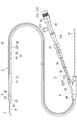
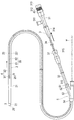
第1実施形態に係る医療用デバイス1は、図1〜4に示すように、内部に超音波診断のためのイメージングコア4を収容して生体管腔内に挿入される超音波カテーテルである。医療用デバイス1は、当該医療用デバイス1を保持してイメージングコア4を駆動させる外部駆動装置7(図7を参照)に接続されて、主として血管内を診断するために使用される。なお、本明細書では、生体の管腔に挿入する側を「先端」若しくは「先端側」、操作する手元側を「基端」若しくは「基端側」と称することとする。   As shown in FIGS. 1 to 4, the medical device 1 according to the first embodiment is an ultrasonic catheter that houses an imaging core 4 for ultrasonic diagnosis and is inserted into a living body lumen. The medical device 1 is connected to an external driving device 7 (see FIG. 7) that holds the medical device 1 and drives the imaging core 4, and is used mainly for diagnosing the inside of a blood vessel. In this specification, the side to be inserted into the lumen of the living body is referred to as “tip” or “tip side”, and the proximal side for operation is referred to as “base end” or “base end side”.

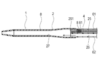
医療用デバイス1は、管腔内に挿入されるシャフト部2と、管腔内組織に向けて超音波を送受信するイメージングコア4(撮像部)と、イメージングコア4が貫通しかつシャフト部2より基端側に位置するハブ5と、イメージングコア4を操作する操作部3と、マーカー8とを備えている。   The medical device 1 includes a shaft portion 2 that is inserted into a lumen, an imaging core 4 (imaging portion) that transmits and receives ultrasonic waves toward the intraluminal tissue, and the imaging core 4 passes through and from the shaft portion 2. A hub 5 located on the proximal end side, an operation unit 3 for operating the imaging core 4, and a marker 8 are provided.

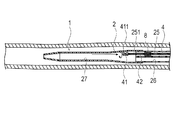
シャフト部2は、シャフト先端部21と、シャフト先端部21の基端側に配置されるシャフト本体部22と、シャフト先端部21の基端側に配置される先端チップ23とを備える。   The shaft portion 2 includes a shaft distal end portion 21, a shaft main body portion 22 disposed on the proximal end side of the shaft distal end portion 21, and a distal end tip 23 disposed on the proximal end side of the shaft distal end portion 21.

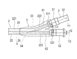
シャフト本体部22は、イメージングコア4が挿入される画像用ルーメン25と、ガイドワイヤWが挿入されるガイドワイヤルーメン26が先端側から基端側まで貫通して形成されている。シャフト本体部22は、先端側にて画像用ルーメン25およびガイドワイヤルーメン26が並んで形成されるシャフト中間部221と、シャフト中間部221から基端方向へ向かって分岐して延びる第1シャフト基端部222および第2シャフト基端部223を備えている。第1シャフト基端部222は、内部に画像用ルーメン25が形成され、第2シャフト基端部223は、内部にガイドワイヤルーメン26が形成されている。シャフト本体部22は、軸線方向の位置によって外径および内径が異なってもよい。例えば、基端側から先端側へ向かって、外径および内径をテーパ状に減少させて物性の極端な変化を生じさせないことで、高い押し込み性、通過性を実現しつつ、キンクの発生を抑制することができる。   The shaft main body 22 is formed by penetrating an image lumen 25 into which the imaging core 4 is inserted and a guide wire lumen 26 into which the guide wire W is inserted from the distal end side to the proximal end side. The shaft main body 22 includes a shaft intermediate portion 221 in which an image lumen 25 and a guide wire lumen 26 are formed side by side on the distal end side, and a first shaft base that extends in a branched manner from the shaft intermediate portion 221 in the proximal direction. An end 222 and a second shaft base end 223 are provided. The first shaft base end portion 222 has an image lumen 25 formed therein, and the second shaft base end portion 223 has a guide wire lumen 26 formed therein. The shaft main body 22 may have different outer diameters and inner diameters depending on the position in the axial direction. For example, by reducing the outer diameter and inner diameter in a tapered shape from the base end side to the tip end side without causing extreme changes in physical properties, high pushability and passability are achieved while suppressing the occurrence of kinks can do.

シャフト本体部22は、画像用ルーメン25が形成される第1管体61と、ガイドワイヤルーメン26が形成される第2管体62とが熱融着(または接着)して形成されており、第1管体61および第2管体62の色が異なり、かつ内部を観察できる程度の透明度を有する。これにより、シャフト部2の内部を観察しつつ、ガイドワイヤWを、画像用ルーメン25ではなくガイドワイヤルーメン26へ選択的に挿入することができる。   The shaft body 22 is formed by heat-sealing (or adhering) a first tubular body 61 in which the image lumen 25 is formed and a second tubular body 62 in which the guide wire lumen 26 is formed. The first tubular body 61 and the second tubular body 62 are different in color and have a transparency that allows the inside to be observed. Accordingly, the guide wire W can be selectively inserted into the guide wire lumen 26 instead of the image lumen 25 while observing the inside of the shaft portion 2.

シャフト先端部21は、画像用ルーメン25およびガイドワイヤルーメン26が合流する1つの共通ルーメン27(シングルルーメンともいう)が形成されている。したがって、共通ルーメン27は、ガイドワイヤルーメン26からガイドワイヤWが入り込むことが可能であるとともに、画像用ルーメン25からイメージングコア4が入り込むことが可能である。   The shaft distal end portion 21 is formed with one common lumen 27 (also referred to as a single lumen) where the image lumen 25 and the guide wire lumen 26 meet. Therefore, the common lumen 27 allows the guide wire W to enter from the guide wire lumen 26 and allows the imaging core 4 to enter from the image lumen 25.

先端チップ23は、シャフト先端部21の一部として構成され、柔軟な材料により形成されてシャフト先端部21の先端側に配置され、共通ルーメン27と連通する先端開口部28が形成される管体である。先端チップ23は、医療用デバイス1を生体管腔内で移動させる際に、接触する生体組織への負担を低減させる。   The distal tip 23 is configured as a part of the shaft distal end portion 21, is formed of a flexible material, is disposed on the distal end side of the shaft distal end portion 21, and has a tubular body in which a distal end opening portion 28 communicating with the common lumen 27 is formed. It is. The distal tip 23 reduces the burden on the living tissue that comes into contact when the medical device 1 is moved within the living body lumen.

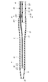
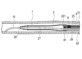
画像用ルーメン25内には、イメージングコア4がシャフト部2の軸線方向にスライド可能に配置されている。このイメージングコア4は、管腔内から生体組織に向けて超音波を送受信するための振動子ユニット41と、この振動子ユニット41を先端に取り付けるとともに回転させる駆動シャフト42とを備える。振動子ユニット41は、超音波を送受信する超音波振動子411と、超音波振動子411を収納するハウジング412とで構成されている。   The imaging core 4 is disposed in the image lumen 25 so as to be slidable in the axial direction of the shaft portion 2. The imaging core 4 includes a transducer unit 41 for transmitting and receiving ultrasonic waves from the lumen toward the living tissue, and a drive shaft 42 that attaches and rotates the transducer unit 41 to the tip. The transducer unit 41 includes an ultrasonic transducer 411 that transmits and receives ultrasonic waves, and a housing 412 that houses the ultrasonic transducer 411.

シャフト先端部21は、超音波の透過性の高い材料により形成されている。シャフト先端部21は、可撓性を有する材料で形成され、その材料は、特に限定されず、例えば、スチレン系、ポリオレフィン系、ポリウレタン系、ポリエステル系、ポリアミド系、ポリイミド系、ポリブタジエン系、トランスポリイソプレン系、フッ素ゴム系、塩素化ポリエチレン系等の各種熱可塑性エラストマー等が挙げられ、これらのうちの1種または2種以上を組合せたもの(ポリマーアロイ、ポリマーブレンド、積層体等)を適用できる。   The shaft tip portion 21 is formed of a material having high ultrasonic permeability. The shaft tip 21 is formed of a flexible material, and the material is not particularly limited. For example, the shaft tip 21 is made of styrene, polyolefin, polyurethane, polyester, polyamide, polyimide, polybutadiene, transpoly. Various thermoplastic elastomers such as isoprene-based, fluororubber-based, and chlorinated polyethylene are listed. One or a combination of two or more of these (polymer alloy, polymer blend, laminate, etc.) can be applied. .

シャフト本体部22は、可撓性を有する材料で形成され、その材料は、特に限定されず、例えば、上述したシャフト先端部21に適用可能な材料を適用できる。   The shaft body 22 is formed of a flexible material, and the material is not particularly limited. For example, a material applicable to the shaft tip 21 described above can be applied.

先端チップ23は、シャフト先端部21よりも柔軟な材料で形成され、その材料は、特に限定されず、例えば、上述したシャフト先端部21に適用可能な材料を適用できる。   The tip tip 23 is formed of a material that is more flexible than the shaft tip portion 21, and the material is not particularly limited. For example, a material applicable to the shaft tip portion 21 described above can be applied.

駆動シャフト42は、柔軟で、しかも操作部3において生成された回転の動力を振動子ユニット41に伝達可能な特性をもち、たとえば、右左右と巻き方向を交互にしている3層コイルなどの多層コイル状の管体で構成されている。駆動シャフト42が回転の動力を伝達することによって、振動子ユニット41が回転し、血管などの管腔内の患部を周方向に亘って観察することができる。また、駆動シャフト42は、振動子ユニット41で検出された信号を操作部3に伝送するための信号線43が内部に通されている。   The drive shaft 42 is flexible and has a characteristic capable of transmitting the rotational power generated in the operation unit 3 to the vibrator unit 41. For example, the drive shaft 42 is a multilayer such as a three-layer coil in which the right and left and the winding directions are alternated. It consists of a coiled tube. When the driving shaft 42 transmits the rotational power, the vibrator unit 41 rotates and the affected part in the lumen such as a blood vessel can be observed in the circumferential direction. The drive shaft 42 has a signal line 43 for transmitting a signal detected by the vibrator unit 41 to the operation unit 3.

ハブ5は、第1シャフト基端部222に気密に連結される第1ハブ部51と、第2シャフト基端部223に気密に連結される第2ハブ部52と、第1ハブ部51および第2ハブ部52を覆うハブ用ケーシング53と、第1耐キンクプロテクタ54とを備えている。   The hub 5 includes a first hub part 51 that is airtightly connected to the first shaft base end part 222, a second hub part 52 that is airtightly connected to the second shaft base end part 223, a first hub part 51, and A hub casing 53 that covers the second hub portion 52 and a first anti-kink protector 54 are provided.

第1ハブ部51には、イメージングコア4を操作するために外部駆動装置7に連結される操作部3が連結されている。操作部3は、第1ハブ部51に連結される外管32と、外管32の基端部に連結されるユニットコネクタ37と、外管32に対して軸線方向へ移動可能な内管34と、内管34の基端部に連結される操作基端部31とを備えている。   The first hub portion 51 is connected to the operation portion 3 connected to the external drive device 7 in order to operate the imaging core 4. The operation unit 3 includes an outer tube 32 coupled to the first hub unit 51, a unit connector 37 coupled to a proximal end portion of the outer tube 32, and an inner tube 34 movable in the axial direction with respect to the outer tube 32. And an operation base end portion 31 connected to the base end portion of the inner tube 34.

操作基端部31は、駆動シャフト42および内管34を保持する。操作基端部31が移動して内管34がユニットコネクタ37および外管32に押し込まれ(図1を参照)、または引き出されることによって(図8を参照)、駆動シャフト42が連動してシャフト部2内を軸線方向にスライドする。操作基端部31には、プライミングのための生理食塩液を注入するポート311が形成されている。ポート311は、画像用ルーメン25に連通している。   The operation base end portion 31 holds the drive shaft 42 and the inner tube 34. When the operation base end portion 31 moves and the inner tube 34 is pushed into the unit connector 37 and the outer tube 32 (see FIG. 1) or pulled out (see FIG. 8), the drive shaft 42 is interlocked with the shaft. Slide in the axial direction in the part 2. A port 311 for injecting physiological saline for priming is formed in the operation base end portion 31. The port 311 communicates with the image lumen 25.

内管34を最も押し込んだときには、図1に示すように、内管34は、先端側の端部が外管32の内部を移動し、第1ハブ部51の付近まで到達する。そして、この状態では、振動子ユニット41は、図2に示すように、シャフト部2の共通ルーメン27の先端付近に位置する。   When the inner tube 34 is pushed in the most, as shown in FIG. 1, the end of the inner tube 34 moves inside the outer tube 32 and reaches the vicinity of the first hub portion 51. In this state, the vibrator unit 41 is located near the tip of the common lumen 27 of the shaft portion 2 as shown in FIG.

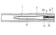
また、内管34を最も引き出したときには、図8に示すように、内管34は、先端に形成されたストッパー315がユニットコネクタ37の内壁に引っかかり、引っかかった先端付近以外が露出する。そして、この状態では、振動子ユニット41は、シャフト部2を残したままその内部を引き戻され、画像用ルーメン25の先端領域により構成される収容部251内に収容される。このように、振動子ユニット41は、血管などの断層画像を作成するために、共通ルーメン27および画像用ルーメン25の内部を、回転しながら軸線方向に沿って移動することができる。   When the inner tube 34 is pulled out most, as shown in FIG. 8, the stopper 315 formed at the tip of the inner tube 34 is caught by the inner wall of the unit connector 37, and the portions other than the vicinity of the caught tip are exposed. In this state, the vibrator unit 41 is pulled back with the shaft portion 2 left, and is housed in the housing portion 251 configured by the distal end region of the image lumen 25. As described above, the transducer unit 41 can move along the axial direction while rotating inside the common lumen 27 and the image lumen 25 in order to create a tomographic image of a blood vessel or the like.

操作基端部31は、ジョイント312と、駆動シャフト42の基端部に接続されたハブ側コネクタ313と、第2耐キンクプロテクタ314とを有する。   The operation base end portion 31 includes a joint 312, a hub side connector 313 connected to the base end portion of the drive shaft 42, and a second kink protector 314.

ジョイント312は、基端側に開口部を有し、ハブ側コネクタ313を内部に配置する。ハブ側コネクタ313は、ジョイント312の基端側から外部駆動装置7が有する駆動側コネクタ711(図7を参照)に連結可能であり、連結することで、外部駆動装置7とハブ側コネクタ313とが機械的および電気的に接続される。   The joint 312 has an opening on the proximal end side, and the hub side connector 313 is disposed inside. The hub-side connector 313 can be connected to the drive-side connector 711 (see FIG. 7) of the external drive device 7 from the base end side of the joint 312. By connecting, the external drive device 7 and the hub-side connector 313 are connected to each other. Are mechanically and electrically connected.

ハブ側コネクタ313には、信号線43の一端が接続されており、この信号線43は、図2に示すように、駆動シャフト42内を通り抜けて、他端が振動子ユニット41に接続されている。外部駆動装置7から駆動側コネクタ711、ハブ側コネクタ313、信号線43を介して振動子ユニット41に送信される信号によって、振動子ユニット41から超音波が照射される。また、超音波を受けることにより振動子ユニット41で検出された信号は、信号線43、ハブ側コネクタ313、駆動側コネクタ711を介して外部駆動装置7へ伝送される。   One end of a signal line 43 is connected to the hub side connector 313, and the signal line 43 passes through the drive shaft 42 and the other end is connected to the vibrator unit 41 as shown in FIG. Yes. The ultrasonic wave is irradiated from the transducer unit 41 by a signal transmitted from the external drive device 7 to the transducer unit 41 via the drive side connector 711, the hub side connector 313, and the signal line 43. Further, a signal detected by the transducer unit 41 by receiving the ultrasonic wave is transmitted to the external drive device 7 via the signal line 43, the hub side connector 313, and the drive side connector 711.

第2耐キンクプロテクタ314は、内管34および操作基端部31の周囲に配置され、内管34のキンクを抑制する。   The second kink protector 314 is disposed around the inner tube 34 and the operation base end portion 31 and suppresses kinking of the inner tube 34.

ユニットコネクタ37は、第1ハブ部51に取り付けられた外管32の基端部が内部に嵌合するように挿入され、この外管32の内部に、操作基端部31から伸びた内管34が挿入される。ユニットコネクタ37は、外部駆動装置9の保持部73(図7を参照)に接続可能である。   The unit connector 37 is inserted so that the base end portion of the outer tube 32 attached to the first hub portion 51 is fitted inside, and the inner tube extending from the operation base end portion 31 is inserted into the outer tube 32. 34 is inserted. The unit connector 37 can be connected to a holding portion 73 (see FIG. 7) of the external drive device 9.

第1ハブ部51は、図1、4に示すように、基端側から外管32の先端部が嵌合して連結されるとともに、先端側から第1シャフト基端部222が挿入されて熱融着または接着して気密に連結されている。したがって、内管34および外管32を通り抜けた駆動シャフト42および生理食塩液は、第1ハブ部51を通って画像用ルーメン25へ移動可能である。第1ハブ部51の外周面には、ハブ用ケーシング53に連結するために、リング状に突出する第1連結用凸部511が形成されている。   As shown in FIGS. 1 and 4, the first hub portion 51 has a distal end portion of the outer tube 32 fitted and connected from the proximal end side, and a first shaft proximal end portion 222 inserted from the distal end side. It is hermetically connected by heat sealing or bonding. Accordingly, the drive shaft 42 and the physiological saline that have passed through the inner tube 34 and the outer tube 32 can move to the image lumen 25 through the first hub portion 51. On the outer peripheral surface of the first hub portion 51, a first connecting convex portion 511 protruding in a ring shape is formed in order to connect to the hub casing 53.

第2ハブ部52は、先端側から第2シャフト基端部223が挿入されて熱融着または接着して気密に連結されている。したがって、第2ハブ部52は、ガイドワイヤルーメン26に連通しており、ガイドワイヤWが通過可能である。第2ハブ部52の外周面には、ハブ用ケーシング53に連結するために、リング状に突出する第2連結用凸部521が形成されている。   The second hub portion 52 is hermetically connected by inserting the second shaft base end portion 223 from the distal end side and heat-sealing or bonding. Accordingly, the second hub portion 52 communicates with the guide wire lumen 26, and the guide wire W can pass therethrough. On the outer peripheral surface of the second hub portion 52, a second connecting convex portion 521 that protrudes in a ring shape is formed in order to connect to the hub casing 53.

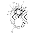
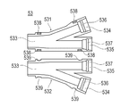
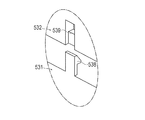
ハブ用ケーシング53は、図4〜6に示すように、シャフト本体部22、第1ハブ部51および第2ハブ部52の外周面を両側から挟むように割型構造で構成される2つの第1ケーシング531および第2ケーシング532を備えている。第1ケーシング531および第2ケーシング532は、シャフト本体部22、第1ケーシング531および第2ケーシング532を挟んで対称的な形状で形成されている。第1ケーシング531および第2ケーシング532は、シャフト本体部22が嵌合する先端側嵌合部533と、第1ハブ部51が嵌合する第1ハブ用嵌合部534と、第2ハブ部52が嵌合する第2ハブ用嵌合部535とが形成されている。   As shown in FIGS. 4 to 6, the hub casing 53 has two second structures configured in a split structure so as to sandwich the outer peripheral surfaces of the shaft main body portion 22, the first hub portion 51, and the second hub portion 52 from both sides. One casing 531 and a second casing 532 are provided. The first casing 531 and the second casing 532 are formed in a symmetrical shape with the shaft main body 22, the first casing 531 and the second casing 532 interposed therebetween. The first casing 531 and the second casing 532 include a distal end side fitting portion 533 into which the shaft main body portion 22 is fitted, a first hub fitting portion 534 into which the first hub portion 51 is fitted, and a second hub portion. A second hub fitting portion 535 into which 52 is fitted is formed.

第1ハブ用嵌合部534には、第1ハブ部51の外周面に形成される第1連結用凸部511が嵌合可能な第1連結用凹部536が形成されている。第2ハブ用嵌合部535には、第2ハブ部52の外周面に形成される第2連結用凸部521が嵌合可能な第2連結用凹部537が形成されている。   The first hub fitting portion 534 is formed with a first connection recess 536 into which the first connection protrusion 511 formed on the outer peripheral surface of the first hub portion 51 can be fitted. The second hub fitting portion 535 is formed with a second coupling recess 537 into which the second coupling projection 521 formed on the outer peripheral surface of the second hub portion 52 can be fitted.

第1ケーシング531および第2ケーシング532には、シャフト本体部22、第1ハブ部51および第2ハブ部52の外周面を両側から挟むように重ねることで、引っ掛かるように連結される連結用フック538および連結用段差部539が形成されている。第1ケーシング531および第2ケーシング532を重ねることで、連結用フック538が一旦撓んだ後に連結用段差部539に引っ掛かり、第1ケーシング531および第2ケーシング532が連結される。なお、第1ケーシング531および第2ケーシング532は、連結用フック538および連結用段差部539のような機械的な構造を用いずに、接着剤や熱融着により接合されてもよい。   The first casing 531 and the second casing 532 are connected to be hooked by overlapping the outer peripheral surfaces of the shaft main body portion 22, the first hub portion 51, and the second hub portion 52 from both sides. 538 and a connecting step 539 are formed. By overlapping the first casing 531 and the second casing 532, the connecting hook 538 is once bent and then hooked to the connecting step 539, so that the first casing 531 and the second casing 532 are connected. The first casing 531 and the second casing 532 may be joined by an adhesive or heat fusion without using a mechanical structure such as the connecting hook 538 and the connecting step 539.

そして、第1ハブ部51の第1連結用凸部511が第1連結用凹部536に嵌合し、かつ第2ハブ部52の第2連結用凸部521が第2連結用凹部537に嵌合した状態で、第1ケーシング531および第2ケーシング532が連結されると、第1ハブ部51および第2ハブ部52がハブ用ケーシング53に対して脱落不能に固定される。なお、第1ハブ部51およびハブ用ケーシング53は、第1連結用凸部511および第1連結用凹部536のような機械的な構造を用いずに、接着剤や熱融着により接合されてもよい。また、第2ハブ部52およびハブ用ケーシング53も、第2連結用凸部521および第2連結用凹部537のような機械的な構造を用いずに、接着剤や熱融着により接合されてもよい。   Then, the first connecting convex portion 511 of the first hub portion 51 is fitted into the first connecting concave portion 536, and the second connecting convex portion 521 of the second hub portion 52 is fitted into the second connecting concave portion 537. When the first casing 531 and the second casing 532 are connected in the combined state, the first hub portion 51 and the second hub portion 52 are fixed to the hub casing 53 so as not to drop off. The first hub portion 51 and the hub casing 53 are joined by an adhesive or heat fusion without using a mechanical structure such as the first connecting convex portion 511 and the first connecting concave portion 536. Also good. Further, the second hub portion 52 and the hub casing 53 are also joined by an adhesive or heat fusion without using a mechanical structure such as the second connection convex portion 521 and the second connection concave portion 537. Also good.

シャフト本体部22は、シャフト中間部221から基端方向に向かって第1シャフト基端部222および第2シャフト基端部223に分岐する部位が、ハブ用ケーシング53の内部に位置している。このため、第1管体61および第2管体62が接合されていないことでシャフト中間部221よりも剛性が低い第1シャフト基端部222および第2シャフト基端部223が、ハブ用ケーシング53の外に位置せず、高い押し込み性を発揮できる。   A portion of the shaft main body 22 that branches from the shaft intermediate portion 221 toward the proximal direction toward the first shaft proximal end portion 222 and the second shaft proximal end portion 223 is located inside the hub casing 53. For this reason, since the first tube body 61 and the second tube body 62 are not joined, the first shaft base end portion 222 and the second shaft base end portion 223 having rigidity lower than that of the shaft intermediate portion 221 are the hub casing. It is not located outside 53, and high pushability can be exhibited.

ハブ用ケーシング53内において、シャフト本体部22の基端部の軸線Xを基準線として、基準線Xに対する第1ハブ部51の中心軸Y1の傾き|θ1|は、基準線Xに対する第2ハブ部52の中心軸Y2の傾き|θ2|よりも大きい。   In the hub casing 53, the inclination | θ1 | of the central axis Y1 of the first hub portion 51 with respect to the reference line X with respect to the axis line X of the base end portion of the shaft main body portion 22 is the second hub with respect to the reference line X. The inclination of the central axis Y2 of the portion 52 is larger than | θ2 |.

第1ハブ部51の傾き|θ1|を大きくし過ぎると、駆動シャフト42と第1シャフト基端部222との摩擦により、画像の回転むらが発生しやすくなる。また、イメージングコア4をプルバックする際に、断線や、イメージングコア4の移動が乱れるジャンピングによる画像むらが発生しやすくなる。したがって、傾き|θ1|は、イメージングコア4に回転むら、断線、ジャンピング等が生じない程度の角度であることが好ましい。   If the inclination | θ1 | of the first hub portion 51 is excessively increased, uneven rotation of the image easily occurs due to friction between the drive shaft 42 and the first shaft base end portion 222. Further, when pulling back the imaging core 4, disconnection and image unevenness due to jumping that disturbs the movement of the imaging core 4 are likely to occur. Therefore, the inclination | θ1 | is preferably an angle that does not cause uneven rotation, disconnection, jumping, or the like in the imaging core 4.

第2ハブ部52の傾き|θ2|を大きくし過ぎると、ガイドワイヤWと第2シャフト基端部223との摩擦により、ガイドワイヤWの操作性が低下する可能性がある。   If the inclination | θ2 | of the second hub portion 52 is excessively increased, the operability of the guide wire W may be reduced due to friction between the guide wire W and the second shaft base end portion 223.

したがって、上記の点を考慮すると、|θ1|≒0、|θ2|≒0であることが好ましいが、第1ハブ部51の中心軸Y1とハブ部52の中心軸Y2の間の角度|θ1−θ2|の値が小さくなるほど、術者によるガイドワイヤWの操作が、外部駆動装置7と干渉するため、|θ1−θ2|の値はできるだけ大きい方が好ましい。   Therefore, considering the above points, | θ1 | ≈0 and | θ2 | ≈0 are preferable, but the angle | θ1 between the center axis Y1 of the first hub portion 51 and the center axis Y2 of the hub portion 52 is | The smaller the value of −θ2 |, the more the value of | θ1−θ2 | is preferable because the operation of the guide wire W by the operator interferes with the external drive device 7.

また、ガイドワイヤWの剛性は、通常、駆動シャフト42の剛性よりかなり高いため、|θ2|≒0であることが好ましい。本実施形態では、|θ2|=0であり、|θ1|>0である。なお、|θ2|が|θ1|以上であってもよい。   Further, since the rigidity of the guide wire W is usually considerably higher than the rigidity of the drive shaft 42, it is preferable that | θ2 | ≈0. In the present embodiment, | θ2 | = 0 and | θ1 |> 0. Note that | θ2 | may be equal to or greater than | θ1 |.

そして、一般的には、ハブ内で曲がらないように配置されるべき駆動シャフト42が、本実施形態では、ハブ5内で曲がって配置される。なお、駆動シャフト42は、血管内で曲がりつつも駆動力を伝達できるように構成されているため、ハブ5内での曲がりを許容できる。そして、駆動シャフト42を収容する画像用ルーメン25が形成されている第1シャフト基端部222が、ハブ用ケーシング53内で、曲がりつつ延びて第1ハブ部51に連結されているため、ハブ用ケーシング53内で回転する駆動シャフト42の位置を適切に保持することができる。   In general, the drive shaft 42 that should be arranged so as not to bend in the hub is bent in the hub 5 in this embodiment. The drive shaft 42 is configured to be able to transmit a driving force while being bent in the blood vessel, so that the drive shaft 42 can be bent in the hub 5. Since the first shaft base end portion 222 in which the image lumen 25 for housing the drive shaft 42 is formed extends while being bent in the hub casing 53 and is connected to the first hub portion 51, the hub The position of the drive shaft 42 rotating in the casing 53 can be appropriately maintained.

また、ガイドワイヤWを収容するガイドワイヤルーメン26が形成されている第2シャフト基端部223が、ハブ用ケーシング53内で、第2ハブ部52に連結されているため、ハブ用ケーシング53内でガイドワイヤWの位置を適切に保持することができ、ガイドワイヤWの良好な操作が可能である。   Further, since the second shaft base end portion 223 in which the guide wire lumen 26 that accommodates the guide wire W is formed is connected to the second hub portion 52 in the hub casing 53, Thus, the position of the guide wire W can be appropriately held, and a satisfactory operation of the guide wire W is possible.

第1耐キンクプロテクタ54は、図1に示すように、ハブ用ケーシング53の先端部およびハブ用ケーシング53から先端方向へ導出されるシャフト本体部22を囲み、シャフト本体部22のキンクを抑制する。   As shown in FIG. 1, the first kink protector 54 surrounds the front end portion of the hub casing 53 and the shaft main body portion 22 led out from the hub casing 53 in the front end direction, and suppresses kink of the shaft main body portion 22. .

第1ハブ部51、第2ハブ部52、ハブ用ケーシング53、管32、内管34、ユニットコネクタ37および操作基端部31の構成材料は、特に限定されず、例えば、ポリ塩化ビニル、ポリエチレン、ポリプロピレン、環状ポリオレフィン、ポリスチレン、ポリ−(4−メチルペンテン−1)、ポリカーボネート、アクリル樹脂、アクリルニトリル−ブタジエン−スチレン共重合体、ポリエチレンテレフタレート、ポリエチレンナフタレート等のポリエステル、ブタジエン−スチレン共重合体、ポリアミド(例えば、ナイロン6、ナイロン6・6、ナイロン6・10、ナイロン12)のような各種樹脂が挙げられる。   The constituent materials of the first hub part 51, the second hub part 52, the hub casing 53, the pipe 32, the inner pipe 34, the unit connector 37, and the operation base end part 31 are not particularly limited. For example, polyvinyl chloride, polyethylene , Polypropylene, cyclic polyolefin, polystyrene, poly- (4-methylpentene-1), polycarbonate, acrylic resin, acrylonitrile-butadiene-styrene copolymer, polyester such as polyethylene terephthalate, polyethylene naphthalate, butadiene-styrene copolymer And various resins such as polyamide (for example, nylon 6, nylon 6,6, nylon 6,10, nylon 12).

画像用ルーメン25には、図1〜3に示すように、振動子ユニット41を収容可能な収容部251の基端側に、駆動シャフト41の回転運動および軸線方向への運動を許容しつつ流体の移動を規制するシール部材8(規制部材)が配置されている。シール部材8は、例えばOリングであり、駆動シャフト41の外周面と接触する。シール部材8は、画像用ルーメン25における流体の、先端方向および基端方向の両方への移動を規制する。シール部材8は、画像用ルーメン25内に嵌合する固定部材81によって軸線方向へ移動不能に固定されている。なおシール部材8は、流体の移動を規制できれば、Oリングでなくてもよく、例えばXリングであってもよい。   As shown in FIGS. 1 to 3, the image lumen 25 allows fluid to be moved while allowing the rotational movement of the drive shaft 41 and the movement in the axial direction to the proximal end side of the accommodating portion 251 that can accommodate the transducer unit 41. A seal member 8 (regulation member) that regulates the movement of is disposed. The seal member 8 is an O-ring, for example, and comes into contact with the outer peripheral surface of the drive shaft 41. The seal member 8 regulates the movement of the fluid in the image lumen 25 in both the distal direction and the proximal direction. The seal member 8 is fixed so as not to move in the axial direction by a fixing member 81 fitted into the image lumen 25. The seal member 8 may not be an O-ring, and may be an X-ring, for example, as long as fluid movement can be restricted.

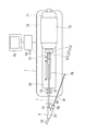
上述した医療用デバイス1は、図7に示すように、外部駆動装置7に接続されて駆動される。外部駆動装置7は、基台75上に、モータ等の外部駆動源を内蔵して駆動シャフト42を回転駆動させる駆動部71と、駆動部71を把持してモータ等により軸線方向へ移動させる移動手段72と、医療用デバイス1の一部を位置固定的に保持する保持部73とを備えている。外部駆動装置7は、駆動部71および移動手段72を制御する制御部79に接続されており、振動子ユニット41によって得られた画像は、制御部79に接続された表示部78に表示される。   The medical device 1 described above is connected to and driven by an external driving device 7 as shown in FIG. The external drive device 7 includes a drive unit 71 that incorporates an external drive source such as a motor on the base 75 and rotationally drives the drive shaft 42, and a movement that grips the drive unit 71 and moves it in the axial direction by the motor or the like. Means 72 and a holding part 73 for holding a part of the medical device 1 in a fixed position are provided. The external drive device 7 is connected to a control unit 79 that controls the drive unit 71 and the moving means 72, and an image obtained by the vibrator unit 41 is displayed on a display unit 78 connected to the control unit 79. .

移動手段72は、駆動部71を把持して固定することが可能であり、把持した駆動部71を、基台75上の溝レール76に沿って前後進させる送り機構である。   The moving means 72 is a feed mechanism that can grip and fix the drive unit 71 and moves the gripped drive unit 71 back and forth along the groove rail 76 on the base 75.

駆動部71は、医療用デバイス1のハブ側コネクタ313が接続可能な駆動用雌コネクタ711と、医療用デバイス1のジョイント312に接続可能なジョイント接続部712と、を有し、当該接続によって、振動子ユニット41との間で信号の送受信が可能となると同時に、駆動シャフト42を回転させることが可能となる。   The drive unit 71 includes a drive female connector 711 to which the hub-side connector 313 of the medical device 1 can be connected, and a joint connection unit 712 that can be connected to the joint 312 of the medical device 1. Signals can be transmitted to and received from the transducer unit 41, and at the same time, the drive shaft 42 can be rotated.

医療用デバイス1における超音波走査(スキャン)は、図7、8に示すように、移動手段72を軸線方向へ移動させつつ、駆動部71内のモータの回転運動を駆動シャフト42に伝達し、駆動シャフト42の先端に固定されたハウジング412を回転させる。これにより、ハウジング412に設けられた超音波振動子411が長手方向に移動しつつ回転し、超音波振動子411で送受信される超音波を略径方向に走査することができる。これにより、血管内の軸方向にわたる包囲組織体における360°の断面画像を任意の位置まで走査的に得ることができる。   As shown in FIGS. 7 and 8, the ultrasonic scanning (scanning) in the medical device 1 transmits the rotational motion of the motor in the drive unit 71 to the drive shaft 42 while moving the moving means 72 in the axial direction. The housing 412 fixed to the tip of the drive shaft 42 is rotated. Accordingly, the ultrasonic transducer 411 provided in the housing 412 rotates while moving in the longitudinal direction, and ultrasonic waves transmitted and received by the ultrasonic transducer 411 can be scanned in a substantially radial direction. Thereby, a 360 ° cross-sectional image of the surrounding tissue body in the axial direction in the blood vessel can be obtained in a scanning manner up to an arbitrary position.

次に、第1実施形態に係る医療用デバイス1を用いて、血管などの生体管腔内から生体組織を観察する際の動作について説明する。   Next, the operation | movement at the time of observing a biological tissue from inside the biological lumens, such as a blood vessel, using the medical device 1 which concerns on 1st Embodiment is demonstrated.

まず、医療用デバイス1のシャフト部2を管腔内に挿入する前に、当該医療用デバイス1内を生理食塩液で満たすプライミング操作を行う。プライミング操作を行うことによって、超音波振動子411から超音波で伝達可能となり、かつ医療用デバイス1内の空気を除去し、血管などの管腔内に空気が入り込むことを防止する。   First, before inserting the shaft portion 2 of the medical device 1 into the lumen, a priming operation for filling the medical device 1 with physiological saline is performed. By performing the priming operation, ultrasonic waves can be transmitted from the ultrasonic transducer 411, and the air in the medical device 1 is removed to prevent the air from entering a lumen such as a blood vessel.

プライミングを行うには、図8、9に示すように、ユニットコネクタ37から操作基端部31を基端側に最も引っ張った状態、すなわち、外管32から内管34が最も引き出された状態にし、振動子ユニット41を、画像用ルーメン25内の収容部251に収容する。次に、ガイドワイヤルーメン26が連通する第2ハブ部52の開口部に、図示しないチューブおよび三方活栓からなる器具を接続し、例えばシリンジ等を用いて、生理食塩液を注入する。注入された生理食塩液は、第2ハブ部52からガイドワイヤルーメン26内に充填されていく。ガイドワイヤルーメン26内の生理食塩液は、共通ルーメン27内に流入し、共通ルーメン27内に流入した生理食塩液は、さらに収容部251内に充填される。なお、収容部251に流入した生理食塩液は、シール部材8により基端方向への移動が規制され、画像用ルーメン25内のシール部材8よりも基端側には流入しない。   In order to perform priming, as shown in FIGS. 8 and 9, the operation base end 31 is most pulled from the unit connector 37 to the base end side, that is, the inner tube 34 is most pulled out from the outer tube 32. The transducer unit 41 is accommodated in the accommodating portion 251 in the image lumen 25. Next, an instrument composed of a tube and a three-way stopcock (not shown) is connected to the opening of the second hub portion 52 that communicates with the guide wire lumen 26, and physiological saline is injected using, for example, a syringe. The injected physiological saline is filled into the guide wire lumen 26 from the second hub portion 52. The physiological saline solution in the guide wire lumen 26 flows into the common lumen 27, and the physiological saline solution that has flowed into the common lumen 27 is further filled in the accommodating portion 251. Note that the physiological saline solution that has flowed into the accommodating portion 251 is restricted from moving in the proximal direction by the seal member 8 and does not flow to the proximal side of the seal member 8 in the image lumen 25.

ガイドワイヤルーメン26から生理食塩液が流入する共通ルーメン27が、生理食塩液で充填されると、先端開口部28から生理食塩液が抜ける。これにより、振動子ユニット41が画像を取得するために移動する共通ルーメン27内および収容部251内の空気が、生理食塩液に置換された状態が確認され、プライミングが完了する。このように、画像用ルーメン25およびガイドワイヤルーメン26が共通ルーメン27で合流しているため、共通ルーメン27のプライミングを、ガイドワイヤルーメン26の基端側の開口部から行うことが可能である。さらに、シール部材8が設けられることで、画像用ルーメン25内の空気の共通ルーメン27への移動が抑制されるため、画像用ルーメン25内をプライミングする必要がなく、プライミング作業が容易となる。また、ガイドワイヤルーメン26からプライミングを行う場合、駆動シャフト42が存在する画像用ルーメン25からプライミングする場合よりも圧力損失が小さいため、小さな力で容易にプライミングを行うことができ、作業性に優れている。なお、振動子ユニット41を共通ルーメン27内に移動させた状態で、プライミングを行うこともできる。   When the common lumen 27 into which the physiological saline solution flows from the guide wire lumen 26 is filled with the physiological saline solution, the physiological saline solution is removed from the distal end opening 28. Thereby, it is confirmed that the air in the common lumen 27 and the accommodating portion 251 in which the transducer unit 41 moves to acquire an image is replaced with physiological saline, and priming is completed. As described above, since the image lumen 25 and the guide wire lumen 26 merge at the common lumen 27, the priming of the common lumen 27 can be performed from the opening on the proximal end side of the guide wire lumen 26. Furthermore, since the seal member 8 is provided, the movement of the air in the image lumen 25 to the common lumen 27 is suppressed, so it is not necessary to prime the image lumen 25 and the priming operation is facilitated. Further, when priming from the guide wire lumen 26, the pressure loss is smaller than when priming from the image lumen 25 in which the drive shaft 42 is present. Therefore, priming can be easily performed with a small force, and workability is excellent. ing. The priming can also be performed in a state where the vibrator unit 41 is moved into the common lumen 27.

次に、図7に示すように、医療用デバイス1を図示しない滅菌されたポリエチレン製の袋などで覆った外部駆動装置7に連結する。すなわち、医療用デバイス1の操作基端部31のジョイント312を、駆動部71のジョイント接続部712に接続する。これにより、振動子ユニット41と外部駆動装置7との間で信号の送受信が可能となると同時に、駆動シャフト42を回転させることが可能となる。そして、ユニットコネクタ37を保持部73に嵌合させると、連結は完了する。   Next, as shown in FIG. 7, the medical device 1 is connected to an external drive device 7 covered with a sterilized polyethylene bag (not shown). That is, the joint 312 of the operation base end portion 31 of the medical device 1 is connected to the joint connection portion 712 of the drive unit 71. As a result, signals can be transmitted and received between the vibrator unit 41 and the external drive device 7, and at the same time, the drive shaft 42 can be rotated. Then, when the unit connector 37 is fitted into the holding portion 73, the connection is completed.

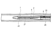
次に、セルジンガー法により経皮的に血管に挿入されたシースを介して、ガイドワイヤWを血管内に挿入する。次に、ガイドワイヤWの基端部を医療用デバイス1の先端開口部28から挿入して、共通ルーメン27を介してガイドワイヤルーメン26内に挿入する。このとき、図10に示すように、共通ルーメン27内にイメージングコア4が位置していないため、イメージングコア4の損傷を抑制できるとともに、ガイドワイヤWの移動が阻害されない。また、第1管体61および第2管体62は、色が異なり、かつ内部を観察できる程度の透明度を有するため、ガイドワイヤWを先端チップ23に形成される先端開口部28から挿入した後、シャフト部2の内部を観察しつつ、共通ルーメン27から画像用ルーメン25へ挿入することなく、ガイドワイヤルーメン26へ挿入することができる。なお、先端開口部28から挿入したガイドワイヤWを、共通ルーメン27からガイドワイヤルーメン26へ挿入する際には、シャフト部2を撓ませることで、画像用ルーメン25ではなくガイドワイヤルーメン26へ向かわせることができる。   Next, the guide wire W is inserted into the blood vessel through the sheath percutaneously inserted into the blood vessel by the Seldinger method. Next, the proximal end portion of the guide wire W is inserted from the distal end opening portion 28 of the medical device 1 and inserted into the guide wire lumen 26 via the common lumen 27. At this time, as shown in FIG. 10, since the imaging core 4 is not located in the common lumen 27, damage to the imaging core 4 can be suppressed and movement of the guide wire W is not hindered. In addition, since the first tube body 61 and the second tube body 62 are different in color and have such a degree of transparency that the inside can be observed, after the guide wire W is inserted from the tip opening portion 28 formed in the tip tip 23, While observing the inside of the shaft portion 2, it can be inserted into the guide wire lumen 26 without being inserted from the common lumen 27 into the image lumen 25. When the guide wire W inserted from the distal end opening 28 is inserted from the common lumen 27 into the guide wire lumen 26, the shaft portion 2 is bent so that the guide wire W is directed to the guide wire lumen 26 instead of the image lumen 25. You can make it.

ガイドワイヤWを第1ハブ部51から基端側へ導出させた後、医療用デバイス1をガイドワイヤWに沿って押し進め、医療用デバイス1の先端部を、観察する患部よりも奥側(先端側)に配置する。このとき、第1ハブ部51と第2ハブ部52は、異なる方向へ向いているため、操作部3や外部駆動装置7に干渉されずに、術者がガイドワイヤWを操作することができる。また、ガイドワイヤルーメン26が、手元の第2ハブ部52で開口しているため、シースから漏れる血液により濡れず、ガイドワイヤWを交換することが容易である。このため、任意の荷重・形状を持つガイドワイヤWを使い分けることにより、複雑な部位の深部に効率的に医療用デバイス1を到達させることが可能である。また、ガイドワイヤルーメン26が、手元の第2ハブ部52で開口しているため、ガイドワイヤルーメン26を介して、造影剤や薬剤を供給し、先端開口部28から生体内へ放出することもできる。   After the guide wire W is led out from the first hub portion 51 to the proximal end side, the medical device 1 is pushed along the guide wire W, and the distal end portion of the medical device 1 is located behind the affected portion to be observed (the distal end). Side). At this time, since the first hub portion 51 and the second hub portion 52 are directed in different directions, the operator can operate the guide wire W without being interfered with the operation portion 3 and the external drive device 7. . In addition, since the guide wire lumen 26 is opened at the second hub portion 52 at hand, the guide wire W can be easily exchanged without getting wet by blood leaking from the sheath. For this reason, it is possible to efficiently reach the medical device 1 to the deep part of a complicated site by properly using the guide wires W having arbitrary loads and shapes. In addition, since the guide wire lumen 26 is opened at the second hub portion 52 at hand, a contrast agent or a drug is supplied via the guide wire lumen 26 and can be released from the distal end opening portion 28 into the living body. it can.

次に、図11に示すように、血管内でシャフト部2を移動しないように保持しつつ、ガイドワイヤWの先端がガイドワイヤルーメン26に収容されるまで、ガイドワイヤWを基端方向へ移動させる。このとき、ガイドワイヤWをガイドワイヤルーメン26から完全に引き抜いてもよい。ガイドワイヤWをガイドワイヤルーメン26から完全に引き抜いても、ガイドワイヤルーメン26が手元の第2ハブ部52で開口しているため、再びガイドワイヤWを挿入することができる。   Next, as shown in FIG. 11, the guide wire W is moved in the proximal direction until the distal end of the guide wire W is accommodated in the guide wire lumen 26 while keeping the shaft portion 2 from moving in the blood vessel. Let At this time, the guide wire W may be completely pulled out from the guide wire lumen 26. Even when the guide wire W is completely pulled out from the guide wire lumen 26, the guide wire W can be inserted again because the guide wire lumen 26 is open at the second hub portion 52 at hand.

この状態で、シャフト部2を移動しないように保持しつつ、駆動部71を基台75上の溝レール76に沿って先端側に動かすことで(図7を参照)、操作基端部31を先端側へ移動させ、外管32に内管34が最も押し込まれた状態とする。これにより、図12に示すように、イメージングコア4は、共通ルーメン27の先端側に移動する。このとき、ガイドワイヤWが共通ルーメン27内に存在しないため、イメージングコア4の損傷を抑制できるとともに、イメージングコア4の動作がガイドワイヤWによって阻害されない。また、駆動シャフト42は、画像用ルーメン25内をシール部材8に接触しつつ先端方向へ移動するため、画像用ルーメン25内の空気が、共通ルーメン27内に移動することを抑制できる。   In this state, the operation base end portion 31 is moved by moving the drive portion 71 to the front end side along the groove rail 76 on the base 75 while holding the shaft portion 2 so as not to move (see FIG. 7). The inner tube 34 is pushed most into the outer tube 32 by moving to the distal end side. Thereby, as shown in FIG. 12, the imaging core 4 moves to the distal end side of the common lumen 27. At this time, since the guide wire W does not exist in the common lumen 27, damage to the imaging core 4 can be suppressed, and the operation of the imaging core 4 is not hindered by the guide wire W. Further, since the drive shaft 42 moves in the distal direction while contacting the seal member 8 in the image lumen 25, it is possible to suppress the air in the image lumen 25 from moving into the common lumen 27.

次に、図13に示すように、駆動シャフト42を駆動部71により回転させながらプルバック操作することで、超音波振動子411をラジアル走査しつつ患部よりも基端側へ軸線方向に沿って移動させて、管腔の軸線方向に沿って、患部を含む生体組織の断層画像を連続して取得する。   Next, as shown in FIG. 13, by performing a pullback operation while rotating the drive shaft 42 by the drive unit 71, the ultrasonic transducer 411 is moved along the axial direction from the affected part to the proximal side while performing radial scanning. Thus, tomographic images of biological tissue including the affected part are continuously acquired along the axial direction of the lumen.

この後、医療用デバイス1を血管内から引き抜き、医療用デバイス1の操作が完了する。   Thereafter, the medical device 1 is pulled out from the blood vessel, and the operation of the medical device 1 is completed.

以上のように、第1実施形態に係る医療用デバイス1は、画像用ルーメン25内の振動子ユニット41(撮像部)よりも基端側に、駆動シャフト42の回転運動および軸線方向への運動を許容しつつ流体の移動を規制するシール部材8が配置されており、画像用ルーメン25の先端側に、画像用ルーメン25およびガイドワイヤルーメン26と連通する共通ルーメン27が形成されている。このため、ガイドワイヤルーメン26のハブ5側の開口部からプライミングを行うことで、シール部材8により画像用ルーメン25内から共通ルーメン27内への気体の移動を規制しつつ、振動子ユニット41が移動する共通ルーメン27内を生理食塩液に置換することが容易となり、プライミングを効率よく行うことが可能となる。   As described above, the medical device 1 according to the first embodiment has the rotational movement and the movement in the axial direction of the drive shaft 42 closer to the proximal end side than the transducer unit 41 (imaging unit) in the image lumen 25. The seal member 8 that restricts the movement of the fluid while permitting the movement is disposed, and a common lumen 27 that communicates with the image lumen 25 and the guide wire lumen 26 is formed on the distal end side of the image lumen 25. For this reason, by performing priming from the opening of the guide wire lumen 26 on the hub 5 side, the vibrator unit 41 is controlled by the seal member 8 while restricting gas movement from the image lumen 25 into the common lumen 27. It becomes easy to replace the moving common lumen 27 with physiological saline, and priming can be performed efficiently.

また、シール部材8が、画像用ルーメン25の先端部にて共通ルーメン27と連通するとともに振動子ユニット41(撮像部)を収容可能な収容部251よりも基端側に配置されるため、ガイドワイヤWを共通ルーメン27に挿入する際に、振動子ユニット41を収容部251へ収容して振動子ユニット41の損傷を抑制できるとともに、ガイドワイヤWの操作性を維持できる。   Further, the seal member 8 communicates with the common lumen 27 at the distal end portion of the image lumen 25 and is disposed closer to the base end side than the accommodating portion 251 capable of accommodating the vibrator unit 41 (imaging portion). When the wire W is inserted into the common lumen 27, the vibrator unit 41 can be housed in the housing portion 251 so that damage to the vibrator unit 41 can be suppressed and the operability of the guide wire W can be maintained.

また、画像用ルーメン25内に、先端側および基端側からの流体の流れを規制するシール部材8が設けられるため、シール部材8によって画像用ルーメン25内から共通ルーメン27内への気体の移動をより確実に規制し、振動子ユニット41への気泡の付着をより確実に抑制できる。
<第2実施形態>
Further, since the seal member 8 for restricting the flow of fluid from the distal end side and the proximal end side is provided in the image lumen 25, the gas movement from the image lumen 25 to the common lumen 27 is performed by the seal member 8. Can be more reliably regulated, and the attachment of bubbles to the vibrator unit 41 can be more reliably suppressed.
Second Embodiment

第2実施形態に係る医療用デバイスは、シャフト先端部の形態のみが、第1実施形態と異なる。なお、第1実施形態と同一の機能を有する部位には、同一の符号を付し、説明を省略する。   The medical device according to the second embodiment differs from the first embodiment only in the form of the shaft tip. In addition, the same code | symbol is attached | subjected to the site | part which has the same function as 1st Embodiment, and description is abbreviate | omitted.

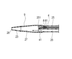
第2実施形態に係る医療用デバイスのシャフト先端部9は、図14に示すように、第1実施形態におけるシャフト先端部21よりも、軸線方向の長さが短い。このような構成とすることで、ガイドワイヤルーメン26のハブ5側の開口部からのプライミングがより容易となり、振動子ユニット41への気泡の付着をより確実に抑制できる。また、駆動シャフト42の軸線方向への移動範囲が短くなることで、シール部材8により画像用ルーメン25内から共通ルーメン27への気体の移動をより効果的に抑制できる。なお、振動子ユニット41を共通ルーメン27の先端側に移動させた状態で、プライミングを行うこともできる。この場合、共通ルーメン27が短いため、振動子ユニット41が、プライミングを行うガイドワイヤルーメン26から近い位置となり、振動子ユニット41への気泡の付着をより確実に抑制でき、より効率的なプライミングが可能となる。
<第3実施形態>
As shown in FIG. 14, the shaft distal end portion 9 of the medical device according to the second embodiment is shorter in the axial direction than the shaft distal end portion 21 in the first embodiment. With such a configuration, priming from the opening of the guide wire lumen 26 on the hub 5 side becomes easier, and the attachment of bubbles to the vibrator unit 41 can be more reliably suppressed. Further, since the moving range of the drive shaft 42 in the axial direction is shortened, the gas movement from the image lumen 25 to the common lumen 27 can be more effectively suppressed by the seal member 8. Note that priming can also be performed in a state where the transducer unit 41 is moved to the distal end side of the common lumen 27. In this case, since the common lumen 27 is short, the vibrator unit 41 is located closer to the guide wire lumen 26 where priming is performed, and it is possible to more reliably suppress the adhesion of bubbles to the vibrator unit 41, and more efficient priming is achieved. It becomes possible.
<Third Embodiment>

第3実施形態に係る医療用デバイスは、規制部材の形態のみが、第1実施形態と異なる。なお、第1実施形態と同一の機能を有する部位には、同一の符号を付し、説明を省略する。   The medical device according to the third embodiment is different from the first embodiment only in the form of the regulating member. In addition, the same code | symbol is attached | subjected to the site | part which has the same function as 1st Embodiment, and description is abbreviate | omitted.

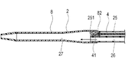
第3実施形態に係る医療用デバイスの規制部材は、図15に示すように、流体の先端方向への移動を制限し、基端方向への移動を許容する逆止弁82である。逆止弁82は、画像用ルーメン25内から共通ルーメン27への気体の移動を規制しつつ、共通ルーメン27内から画像用ルーメン25への生理食塩液の流入を許容するように構成されている。このような構成とすることで、ガイドワイヤルーメン26のハブ5側の開口部からのプライミングを行うと、共通ルーメン27へ流入した生理食塩液が、逆止弁82を通って画像用ルーメン25へ流入し、画像用ルーメン25内の気体が生理食塩液に置換される。このため、画像用ルーメン25内から共通ルーメン27への気体の移動をより確実に抑制し、振動子ユニット41への気泡の付着をより確実に抑制できる。なお逆止弁の位置は、画像用ルーメン25内の先端側に限定されず、任意の位置に設置することができる。
<第4実施形態>
As shown in FIG. 15, the restricting member of the medical device according to the third embodiment is a check valve 82 that restricts movement of the fluid in the distal direction and allows movement in the proximal direction. The check valve 82 is configured to allow an inflow of physiological saline from the common lumen 27 to the image lumen 25 while restricting the movement of gas from the image lumen 25 to the common lumen 27. . With this configuration, when priming from the opening on the hub 5 side of the guide wire lumen 26 is performed, the physiological saline solution that has flowed into the common lumen 27 passes through the check valve 82 and enters the image lumen 25. The gas in the image lumen 25 is replaced with physiological saline. For this reason, the movement of the gas from the image lumen 25 to the common lumen 27 can be more reliably suppressed, and the attachment of bubbles to the vibrator unit 41 can be more reliably suppressed. The position of the check valve is not limited to the distal end side in the image lumen 25, and can be installed at an arbitrary position.
<Fourth embodiment>

第4実施形態に係る医療用デバイスは、規制部材の形態のみが、第1実施形態と異なる。なお、第1実施形態と同一の機能を有する部位には、同一の符号を付し、説明を省略する。   The medical device according to the fourth embodiment is different from the first embodiment only in the form of the regulating member. In addition, the same code | symbol is attached | subjected to the site | part which has the same function as 1st Embodiment, and description is abbreviate | omitted.

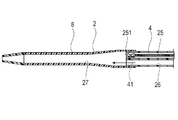
第4実施形態に係る医療用デバイスは、図16に示すように、画像用ルーメン25内に、規制部材が設けられていない。ただし、操作基端部31のポート311(図1を参照)に、図示しないチューブおよび三方活栓からなる器具など(規制部材)を接続して密封する。このような構成とすることで、ガイドワイヤルーメン26のハブ5側の開口部からプライミングする際に、画像用ルーメン25内の内圧により、共通ルーメン27から画像用ルーメン25へ生理食塩液がほとんど流入しない。しかしながら、同時に、画像用ルーメン25内の気体の共通ルーメン27への移動も制限されるため、振動子ユニット41への気泡の付着を極力抑制することができる。   As shown in FIG. 16, the medical device according to the fourth embodiment is not provided with a regulating member in the image lumen 25. However, an instrument or the like (regulating member) composed of a tube and a three-way cock (not shown) is connected to the port 311 (see FIG. 1) of the operation base end portion 31 and sealed. With such a configuration, when priming from the opening on the hub 5 side of the guide wire lumen 26, the physiological saline almost flows into the image lumen 25 from the common lumen 27 due to the internal pressure in the image lumen 25. do not do. However, at the same time, the movement of the gas in the image lumen 25 to the common lumen 27 is also restricted, so that bubbles can be prevented from adhering to the transducer unit 41 as much as possible.

なお、本発明は、上述した実施形態のみに限定されるものではなく、本発明の技術的思想内において当業者により種々変更が可能である。例えば、上記実施の形態では、本発明を超音波カテーテルに適用する場合について説明したが、光干渉断層診断装置(OCT:Optical Coherence Tomography)や光学周波数領域画像化診断装置(OFDI:Optical Frequency Domain Imaging)などの光を利用して画像を取得する装置に適用することも可能である。   Note that the present invention is not limited to the above-described embodiments, and various modifications can be made by those skilled in the art within the technical idea of the present invention. For example, in the above-described embodiment, the case where the present invention is applied to an ultrasonic catheter has been described. However, an optical coherence tomography diagnostic apparatus (OCT) or an optical frequency domain imaging diagnostic apparatus (OFDI) is used. It is also possible to apply to an apparatus that acquires an image using light such as.

1 医療用デバイス、
2 シャフト部、
21 シャフト先端部、
22 シャフト本体部、
221 シャフト中間部、
222 第1シャフト基端部、
223 第2シャフト基端部、
23 先端チップ、
25 画像用ルーメン、
251 収容部、
26 ガイドワイヤルーメン、
27 共通ルーメン、
28 先端開口部、
4 イメージングコア、
41 振動子ユニット(撮像部)、
411 超音波振動子、
42 駆動シャフト、
5 ハブ、
51 第1ハブ部、
52 第2ハブ部、
53 ハブ用ケーシング、
531 第1ケーシング、
532 第2ケーシング、
8 シール部材(規制部材)、
82 逆止弁(規制部材)、
W ガイドワイヤ。
1 medical device,
2 shaft part,
21 Shaft tip,
22 Shaft body,
221 shaft middle part,
222 first shaft proximal end,
223 second shaft proximal end,
23 Tip,
25 Lumen for images,
251 receiving section,
26 Guidewire lumen,
27 Common lumens,
28 Tip opening,
4 Imaging core,
41 transducer unit (imaging unit),
411 ultrasonic transducer,
42 drive shaft,
5 Hub,
51 1st hub part,
52 second hub part,
53 Hub casing,
531 first casing,
532 second casing,
8 Seal member (regulator member),
82 Check valve (regulating member),
W Guide wire.

Claims (4)

生体管腔内に挿入して画像を取得するための医療用デバイスであって、
画像を取得するための画像用ルーメンおよびガイドワイヤ用のガイドワイヤルーメンが形成されるシャフト本体部と、
前記シャフト本体部の先端側に形成されて前記画像用ルーメンおよびガイドワイヤルーメンと連通して先端側で開口する共通ルーメンが形成されるシャフト先端部と、
前記シャフト本体部の基端部が連結されて前記画像用ルーメンおよびガイドワイヤルーメンが開口するハブと、
前記画像用ルーメン内で回転方向および軸線方向への移動が可能な駆動シャフトと、
前記駆動シャフトの先端に固定されて画像情報を取得可能であり、前記駆動シャフトにより駆動されて前記共通ルーメンおよび画像用ルーメンの少なくとも共通ルーメン内を移動可能な撮像部と、
前記画像用ルーメン内の前記撮像部よりも基端側に配置されて前記駆動シャフトの回転運動および軸線方向への運動を許容しつつ流体の移動を規制する規制部材と、を有する医療用デバイス。
A medical device for acquiring an image by being inserted into a living body lumen,
A shaft main body portion on which an image lumen for acquiring an image and a guide wire lumen for a guide wire are formed;
A shaft distal end portion formed on the distal end side of the shaft main body portion to form a common lumen communicating with the image lumen and the guide wire lumen and opening on the distal end side;
A hub to which the base end portion of the shaft main body portion is coupled and the image lumen and the guide wire lumen are opened;
A drive shaft capable of moving in the rotational direction and the axial direction within the image lumen;
An image pickup unit that is fixed to the tip of the drive shaft and is capable of acquiring image information, and that is driven by the drive shaft and is movable within at least the common lumen of the common lumen and the image lumen;
A medical device, comprising: a regulating member that is disposed on a proximal end side with respect to the imaging unit in the imaging lumen and regulates fluid movement while allowing rotational movement and axial movement of the drive shaft.
前記規制部材は、前記画像用ルーメンの先端部にて前記共通ルーメンと連通するとともに前記撮像部を収容可能な収容部よりも基端側に配置される請求項1に記載の医療用デバイス。   2. The medical device according to claim 1, wherein the restriction member communicates with the common lumen at a distal end portion of the imaging lumen and is disposed on a proximal end side with respect to a housing portion capable of housing the imaging unit. 前記規制部材は、先端側および基端側からの流体の流れを規制するシール部材である請求項1または2に記載の医療用デバイス。   The medical device according to claim 1, wherein the regulating member is a seal member that regulates a flow of fluid from a distal end side and a proximal end side. 前記規制部材は、基端側からの流体の流れを規制する逆止弁である請求項1または2に記載の医療用デバイス。   The medical device according to claim 1, wherein the regulating member is a check valve that regulates a flow of fluid from a proximal end side.
JP2015002045A 2015-01-08 2015-01-08 Medical device Pending JP2016123795A (en)

Priority Applications (1)

Application Number Priority Date Filing Date Title
JP2015002045A JP2016123795A (en) 2015-01-08 2015-01-08 Medical device

Applications Claiming Priority (1)

Application Number Priority Date Filing Date Title
JP2015002045A JP2016123795A (en) 2015-01-08 2015-01-08 Medical device

Publications (1)

Publication Number Publication Date
JP2016123795A true JP2016123795A (en) 2016-07-11

Family

ID=56358480

Family Applications (1)

Application Number Title Priority Date Filing Date
JP2015002045A Pending JP2016123795A (en) 2015-01-08 2015-01-08 Medical device

Country Status (1)

Country Link
JP (1) JP2016123795A (en)

Citations (4)

* Cited by examiner, † Cited by third party
Publication number Priority date Publication date Assignee Title
JPH09289968A (en) * 1996-04-26 1997-11-11 Olympus Optical Co Ltd Intra-celom ultrasonic diagnostic system
US5707354A (en) * 1995-04-17 1998-01-13 Cardiovascular Imaging Systems, Inc. Compliant catheter lumen and methods
JPH10118071A (en) * 1996-10-16 1998-05-12 Olympus Optical Co Ltd Ultrasonic endoscope
JP2000189517A (en) * 1998-12-25 2000-07-11 Terumo Corp Ultrasonic catheter

Patent Citations (4)

* Cited by examiner, † Cited by third party
Publication number Priority date Publication date Assignee Title
US5707354A (en) * 1995-04-17 1998-01-13 Cardiovascular Imaging Systems, Inc. Compliant catheter lumen and methods
JPH09289968A (en) * 1996-04-26 1997-11-11 Olympus Optical Co Ltd Intra-celom ultrasonic diagnostic system
JPH10118071A (en) * 1996-10-16 1998-05-12 Olympus Optical Co Ltd Ultrasonic endoscope
JP2000189517A (en) * 1998-12-25 2000-07-11 Terumo Corp Ultrasonic catheter

Similar Documents

Publication Publication Date Title
JP5399301B2 (en) catheter
JP6110363B2 (en) catheter
JP5188242B2 (en) In vivo insertion probe
US10842465B2 (en) Medical device
WO2014188509A1 (en) Catheter
JP2012050706A (en) Protective cover
US11445999B2 (en) Medical device
JP6647080B2 (en) Medical devices
JP6591987B2 (en) Medical device
JP6625067B2 (en) Medical devices
JP5171354B2 (en) In vivo diagnostic imaging probe
JP6720021B2 (en) Medical device
JP6599702B2 (en) Diagnostic imaging catheter
JP6823043B2 (en) Medical device
JP2016123795A (en) Medical device
JP2018047063A (en) Connection port and medical device
JP6779799B2 (en) Medical device
JP6247160B2 (en) Medical device
JP2018033697A (en) Medical device
WO2014162492A1 (en) Catheter for image diagnosis
JP7470717B2 (en) Catheter assembly and bundling method
JP2018042819A (en) Medical device
JP2018033614A (en) Medical device
JP2014014591A (en) Medical device
JP2012205661A (en) Catheter assembly

Legal Events

Date Code Title Description
A621 Written request for application examination

Free format text: JAPANESE INTERMEDIATE CODE: A621

Effective date: 20171212

A977 Report on retrieval

Free format text: JAPANESE INTERMEDIATE CODE: A971007

Effective date: 20180829

A131 Notification of reasons for refusal

Free format text: JAPANESE INTERMEDIATE CODE: A131

Effective date: 20180910

A601 Written request for extension of time

Free format text: JAPANESE INTERMEDIATE CODE: A601

Effective date: 20181109

A521 Request for written amendment filed

Free format text: JAPANESE INTERMEDIATE CODE: A523

Effective date: 20190108

A02 Decision of refusal

Free format text: JAPANESE INTERMEDIATE CODE: A02

Effective date: 20190311