JP2016123728A - Ball equipment - Google Patents
Ball equipment Download PDFInfo
- Publication number
- JP2016123728A JP2016123728A JP2015000441A JP2015000441A JP2016123728A JP 2016123728 A JP2016123728 A JP 2016123728A JP 2015000441 A JP2015000441 A JP 2015000441A JP 2015000441 A JP2015000441 A JP 2015000441A JP 2016123728 A JP2016123728 A JP 2016123728A
- Authority
- JP
- Japan
- Prior art keywords
- bowling
- pin
- collided
- ball
- juxtaposed
- Prior art date
- Legal status (The legal status is an assumption and is not a legal conclusion. Google has not performed a legal analysis and makes no representation as to the accuracy of the status listed.)
- Granted
Links
- 230000032258 transport Effects 0.000 claims description 34
- 239000011159 matrix material Substances 0.000 claims description 7
- 239000000696 magnetic material Substances 0.000 claims description 5
- 230000007717 exclusion Effects 0.000 description 22
- 230000007246 mechanism Effects 0.000 description 16
- 230000001174 ascending effect Effects 0.000 description 5
- 230000006399 behavior Effects 0.000 description 5
- 230000008859 change Effects 0.000 description 5
- 238000010586 diagram Methods 0.000 description 5
- 238000000034 method Methods 0.000 description 5
- 238000011084 recovery Methods 0.000 description 5
- 239000000725 suspension Substances 0.000 description 5
- 239000011295 pitch Substances 0.000 description 4
- 238000012545 processing Methods 0.000 description 4
- 238000005096 rolling process Methods 0.000 description 4
- 238000013459 approach Methods 0.000 description 3
- 230000005284 excitation Effects 0.000 description 3
- 238000007796 conventional method Methods 0.000 description 2
- 238000001514 detection method Methods 0.000 description 2
- 230000000630 rising effect Effects 0.000 description 2
- 241001417527 Pempheridae Species 0.000 description 1
- 235000002597 Solanum melongena Nutrition 0.000 description 1
- 244000061458 Solanum melongena Species 0.000 description 1
- 238000011161 development Methods 0.000 description 1
- 230000003028 elevating effect Effects 0.000 description 1
- 230000005389 magnetism Effects 0.000 description 1
- 238000012986 modification Methods 0.000 description 1
- 230000004048 modification Effects 0.000 description 1
- 230000008569 process Effects 0.000 description 1
- 239000002023 wood Substances 0.000 description 1
Images


Classifications
-
- A—HUMAN NECESSITIES
- A63—SPORTS; GAMES; AMUSEMENTS
- A63D—BOWLING GAMES, e.g. SKITTLES, BOCCE OR BOWLS; INSTALLATIONS THEREFOR; BAGATELLE OR SIMILAR GAMES; BILLIARDS
- A63D5/00—Accessories for bowling-alleys or table alleys
- A63D5/08—Arrangements for setting-up or taking away pins
Landscapes
- Toys (AREA)
Abstract
Description
本発明は、ゲーム性を向上させた進化型の球技の実施を実現する球技装置に関する。 The present invention relates to a ball game apparatus that implements an evolutionary ball game with improved game performance.
ボウリングは、ボールをボウリングピンに当てて倒し、倒れた数に応じて得られる得点を競うゲームである。このボウリングは、ボウリング装置を使用して行なわれる。ボウリング装置は、プレイヤーが投げるボールと、プレイヤーの投球エリアであるアプローチと、該アプローチから続くようにして投げられたボールが転がり進むレーンと、該レーンの終端部のピンデッキと、該ピンデッキに並置され、ボールによって倒される対象である複数のボウリングピンと、該ボウリングピンをピンデッキに並置するピンセッターと、ボウリングピン及びボールをレーン及びピンデッキ上から取り除くスイーパーとを含んで構成される。 Bowling is a game in which a ball is defeated by hitting it with a bowling pin, and a score is obtained according to the number of falls. This bowling is performed using a bowling device. The bowling device is juxtaposed with the ball thrown by the player, the approach that is the player's throwing area, the lane in which the ball thrown from the approach rolls, the pin deck at the end of the lane, and the pin deck. And a plurality of bowling pins that are to be overturned by the ball, a pin setter for juxtaposing the bowling pins to the pin deck, and a sweeper for removing the bowling pins and the ball from the lane and the pin deck.
ボウリングピンの形状及び寸法は国内及び国際的に規定されている。規定されたボウリングピンは、外形が長細で起立可能に構成されており、断面形状はいずれの箇所でも円形をなし、高さの半分から少し上の部分に滑らかなくびれを有し、該くびれよりも上側の頭部は略半球状の頂部を有し、頭部の径はくびれよりも下側の胴体部の径よりも小さく、胴体部は底部に向けて滑らかに縮径された形状をなす。 The shape and dimensions of the bowling pins are defined nationally and internationally. The specified bowling pin has a long outer shape and is configured to be able to stand up, and the cross-sectional shape is circular at any point, and has a smooth constriction in a portion slightly above the half of the height. The upper head has a substantially hemispherical top, the diameter of the head is smaller than the diameter of the body part below the constriction, and the body part has a shape that is smoothly reduced in diameter toward the bottom part. Eggplant.
ピンセッターは、上述したような形状のボウリングピン10本を、ピンデッキ上に並置する。並置の態様は、ボウリングピン10本の包絡線が正三角形状をなすように規定されており、ボウリングピン同士の間隔も規定されている。特許文献1には規定された並置の態様の範囲内で、任意の箇所にボウリングピンを置くことが可能な磁性体及び電磁石を利用したピンセッターの発明が開示されている。
The pin setter juxtaposes ten bowling pins shaped as described above on a pin deck. The juxtaposition mode is defined such that the envelopes of the ten bowling pins form an equilateral triangle, and the interval between the bowling pins is also defined.
上述のようにボウリングは、ピンの形状及び寸法、並びに並置態様が規定されている。しかしながら規定範囲内で競う場合には、高技術者同士の技術の差異が生じ難い。そこで、ボールが転がるレーン上に油を塗り、しかも油の塗り方に各レーンで差異が生じるようにしてプレイヤーに技術介入の余地を与えている現状であり、ピンを倒すというゲーム自体の魅力が低減している。また従来のボウリング装置は、ボウリングピンを10回かそれ以上全く同じ並び方で並置するから、プレイヤーは同じような投球を淡々と繰り返していく。したがって競技として観戦者にもたらす驚きや感動が不足している。
As described above, the shape and dimensions of the pins and the juxtaposition mode of the bowling are defined. However, when competing within the specified range, it is difficult for technical differences between high engineers to occur. Therefore, oil is applied to the lane where the ball rolls, and there is a difference in how to apply the oil in each lane, giving the player room for technical intervention. Reduced. In addition, since the conventional bowling device juxtaposes the
本発明は斯かる事情に鑑みてなされたものであり、ゲーム性を向上させた進化型の球技の実施を実現する球技装置を提供することを目的とする。 The present invention has been made in view of such circumstances, and an object thereof is to provide a ball game apparatus that implements an evolutionary ball game with improved game performance.
本発明に係る球技装置は、投擲される球が転がる経路と、該経路上の並置領域に並置され、前記球によって衝突される複数の被衝突体と、該複数の被衝突体を前記並置領域内に並置する並置装置とを含む球技装置において、前記複数の被衝突体の夫々は、一部又は全部が球体からなることを特徴とする。 A ball game apparatus according to the present invention includes a path on which a thrown ball rolls, a plurality of collided objects that are juxtaposed in a juxtaposed area on the path, and collided by the spheres, and the plurality of collided bodies are arranged in the juxtaposed area. In the ball game apparatus including the juxtaposition device juxtaposed therein, each of the plurality of the collided bodies is characterized in that a part or all of the colliding bodies is formed of a sphere.
本発明に係る球技装置は、前記並置装置は、前記複数の被衝突体を溜め置く溜置部と、前記複数の被衝突体を支持して前記並置領域へ搬送する搬送部と、矩形領域である前記並置領域内の任意の位置に前記複数の被衝突体が並置されるよう前記搬送部による搬送先を決定する決定部とを備えることを特徴とする。 In the ball game apparatus according to the present invention, the juxtaposition device includes: a storage unit that stores the plurality of collided bodies; a transport unit that supports the plurality of collided bodies and transports them to the juxtaposition region; and a rectangular region. And a determining unit that determines a transport destination by the transport unit so that the plurality of collided bodies are juxtaposed at an arbitrary position in the juxtaposed region.
本発明に係る球技装置は、前記被衝突体は磁性体を含み、前記搬送部は電磁石を備えることを特徴とする。 In the ball game apparatus according to the present invention, the collision object includes a magnetic body, and the transport unit includes an electromagnet.
本発明に係る球技装置は、前記搬送部はマトリクス状に並べられた複数の電磁石を備え、前記複数の被衝突体を同時的に搬送するようにしてあり、前記溜置部は、前記搬送部の前記マトリクスに対応する矩形状の範囲内に前記複数の被衝突体を並べて溜め置くようにしてあり、前記決定部は、前記複数の電磁石の内から励磁させる電磁石を決定するようにしてあることを特徴とする。 In the ball game apparatus according to the present invention, the transport unit includes a plurality of electromagnets arranged in a matrix, and transports the plurality of collided bodies simultaneously, and the storage unit includes the transport unit. The plurality of impacted bodies are arranged and stored in a rectangular range corresponding to the matrix, and the determination unit determines an electromagnet to be excited from among the plurality of electromagnets. It is characterized by.
本発明では、ボウリングにおけるボウリングピンに相当する被衝突体の一部又は全部が球体からなる。被衝突体が球体として動くので、球(ボール)に衝突された場合の動きと、その後他の被衝突体への衝突の仕方の予測が可能になる。また、従来のボウリングピンの倒れ方よりも偶発性を低減できるため、プレイヤー間の技術の差を従来よりも得点に反映させることが可能となる。なお全ての被衝突体を衝突させることの難易度を上げることが可能になり、高技術者が更に技術を向上させる伸び代が生じる。 In the present invention, a part or all of the colliding object corresponding to the bowling pin in the bowling is made of a sphere. Since the collided object moves as a sphere, it is possible to predict the movement when colliding with a sphere (ball) and how to collide with another collided object thereafter. Further, since the randomness can be reduced as compared with the conventional method of falling the bowling pin, it is possible to reflect the technical difference between the players in the score as compared with the conventional method. In addition, it becomes possible to raise the difficulty of colliding all the to-be-collised bodies, and the elongation allowance which a high engineer further improves a technique arises.
本発明では、複数の被衝突体の並置態様は、従来のボウリングピンのように平面視が正三角形状となる態様のみならず、矩形領域内で任意の形状となるような並び方が可能となる。これにより、プレイヤーの技術に応じて並置態様を変更して難易度を変更すること、及び、並置態様を1投球ずつ変更することが可能となる。 In the present invention, the side-by-side arrangement of a plurality of collided objects is not limited to an aspect in which the plan view is an equilateral triangle like a conventional bowling pin, but can be arranged in an arbitrary shape within a rectangular region. . This makes it possible to change the juxtaposition mode according to the player's technique to change the difficulty level, and to change the juxtaposition mode one pitch at a time.
本発明では、複数の被衝突体の並置は磁気を利用する。これにより、被衝突体の並び方の自由度を容易に向上させることが可能となる。電磁石をマトリクス状に使用する構成では、自由度の高い並置態様を容易に実現することが可能となる。 In the present invention, magnetism is used for juxtaposition of a plurality of collision objects. Thereby, it is possible to easily improve the degree of freedom in arranging the collided bodies. In the configuration in which the electromagnets are used in a matrix, it is possible to easily realize a juxtaposition mode with a high degree of freedom.
本発明による場合、被衝突体の動きが予測可能となり、更にプレイヤーの実力の差を反映させることが可能となるのでゲーム性が向上し、プレイヤーは目標をより高く設定して技術を向上させることができ、発展性が向上する。また、プレイヤーの実力に合わせて難易度を調整することができ、観戦者への魅力も向上する。 According to the present invention, the movement of the collision object can be predicted, and further, the difference in the ability of the player can be reflected, so that the game performance is improved, and the player can improve the technique by setting the target higher. And development is improved. In addition, the difficulty level can be adjusted according to the player's ability, and the appeal to the spectator is improved.
以下、本発明をその実施の形態を示す図面に基づいて具体的に説明する。 Hereinafter, the present invention will be specifically described with reference to the drawings showing embodiments thereof.
なお以下の説明では、被衝突体の形状について複数の実施の形態を挙げて説明し、それらの複数の態様の被衝突体夫々を並置するための並置装置については後述にて具体的に説明する。また本発明では、従来のボウリング装置におけるボウリングピンに相当する被衝突体を、一部又は全部が球体で構成する。この意味でボウリングの規定から外れるが、以下の実施の形態では被衝突体をボウリングピンと呼び、被衝突体を並置する並置装置をピンセッターと呼んで説明する。 In the following description, the shape of the collided body will be described with reference to a plurality of embodiments, and the juxtaposition device for juxtaposing the collided bodies of the plurality of modes will be described in detail later. . Further, in the present invention, a part or all of the collided body corresponding to the bowling pin in the conventional bowling device is constituted by a sphere. In this sense, it is out of the definition of bowling. However, in the following embodiments, a collision target will be referred to as a bowling pin, and a juxtaposition device for juxtaposing the collision target will be referred to as a pin setter.
(実施の形態1)
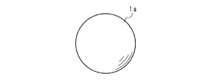
図1は、実施の形態1におけるボウリングピンを示す正面図である。図1に示すように実施の形態1におけるボウリングピン1aは球体である。ボウリングピン1aは、例えば木製であり、衝突した際の音を響かせるために内部に空洞が設けられていてもよい。
(Embodiment 1)
FIG. 1 is a front view showing a bowling pin in the first embodiment. As shown in FIG. 1, the
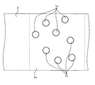
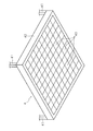
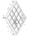
図2は、実施の形態1におけるボウリングピン1aの並び方の一例を示す上面図である。符号2は、ボールが通過する経路(レーン)である。レーン2の終端部にはボウリングピン1aを並置する並置領域であるピンデッキ2aが設けられている。ボウリングピン1aの並置態様は図2に示す如く、矩形のピンデッキ2a内の任意の位置に並置される。このとき、包絡線が正三角形状となるような並置態様以外が好ましい。また並置されるボウリングピン1aの数は任意である。
FIG. 2 is a top view showing an example of how the bowling pins 1a are arranged in the first embodiment.
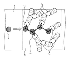
図3は、ボウリングピン1aの動きを模式的に示す説明図である。図3中の符号3は投擲されたボールを示している。投擲されたボール3がレーン2上を進むとボウリングピン1aのいずれかに衝突する。衝突されたボウリングピン1aは他のボウリングピン1aに更に衝突する。またボール3は複数のボウリングピン1aに衝突しながら、レーン2上を進む。このとき、ボール3及びボウリングピン1aはいずれも球体として転動、滑動するので、ビリヤードの球の如く予測が可能である。
FIG. 3 is an explanatory view schematically showing the movement of the
なお球体のボウリングピン1aの“倒数”のカウントの仕方は様々な方法が考えられる。例えばピンデッキ2a上方に、ピンデッキ2a全体を撮影範囲に含むようにカメラを設置し、カメラで撮像される画像に対する画像処理をピンセッターの制御機構で実行し、ボウリングピン1aがボール3又は他のボウリングピン1aに衝突されて当初の位置から所定の距離以上動いた場合に“倒数”にカウントする。更に、ボール3又は他のボウリングピン1aに衝突されて完全にピンデッキ2a外に出た場合に“倒数”にカウントするようにしてもよい。又は、ピンデッキ2a上方に赤外線等を用いたセンサを設け、各ボウリングピン1aが動いたか否かを個別に判断するようにしてもよい。
Various methods can be considered for counting the “falling number” of the
なお、実施の形態1のボウリングピン1aは全部が球体からなるので、ボール3の衝突以外の振動等では並置状態を保つためにピンデッキ2aに極小の突起物、毛せん、弾性体を設けるなどしてもよい。
Since the
(実施の形態2)
図4は、実施の形態2におけるボウリングピンを示す正面図であり、図5はボウリングピンの底面図である。図4、図5に示す如く、実施の形態2におけるボウリングピン1bは、球体の一部を切り欠き平坦な底部12bを設けた形状をなす。ボウリング1bは底部12bの存在により、並置状態が安定して保たれる。なお底部12bの大きさは、ボウリングピン1bの球体としての挙動を阻害しない程度の大きさで、できるだけ小さいことが好ましい。ボウリングピン1bは自立可能であるから実施の形態1で説明したようなピンデッキの突起物、毛せん、弾性体は不要となる。
(Embodiment 2)
FIG. 4 is a front view showing the bowling pin in the second embodiment, and FIG. 5 is a bottom view of the bowling pin. As shown in FIGS. 4 and 5, the bowling pin 1b according to the second embodiment has a shape in which a part of a sphere is cut out and a
(実施の形態3)
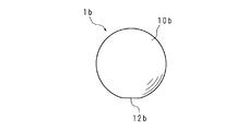
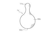
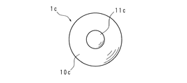
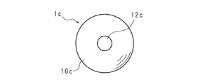
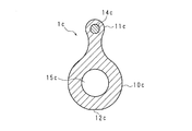
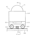
図6は、実施の形態3におけるボウリングピンを示す正面図であり、図7は、ボウリングピンを示す上面図、図8は、ボウリングピンを示す底面図である。図6〜図8に示す如く、実施の形態3におけるボウリングピン1cは、球体の一部を切り欠き、実施の形態2におけるボウリングピン1b同様に平坦な底部12cを設け、更に、底部12cと反対側に頭部11cを設けてある。頭部11cは球体状をなし、球体部10cに滑らかなくびれを介して接続されている。実施の形態3のボウリングピン1cのように頭部11cを設けることで、ボウリングユーザに生じさせる違和感を軽減し、更に“倒数”のカウントが従来のボウリング装置と同様に容易になる。
(Embodiment 3)
6 is a front view showing the bowling pin in the third embodiment, FIG. 7 is a top view showing the bowling pin, and FIG. 8 is a bottom view showing the bowling pin. As shown in FIGS. 6 to 8, the
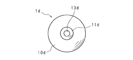
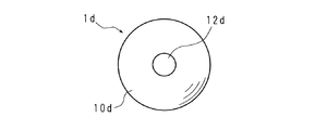
(実施の形態4)
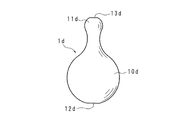
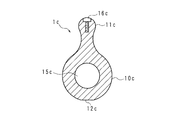
図9は、実施の形態4におけるボウリングピンを示す正面図であり、図10は上面図、図11は底面図である。図9〜図11に示す如く、実施の形態4におけるボウリングピン1dは、球体の一部を切り欠き、実施の形態2におけるボウリングピン1b同様に平坦な底部12dを設け、更に、底部12dと反対側に頭部11dを設けてある。頭部11dは実施の形態3におけるボウリングピン1c同様に球体状をなし、球体部10dに滑らかなくびれを介して接続されているが、頭部11dの頂部に平坦部13dが設けられている。底部12dと頭部11dの平坦部13dとでは、平坦部13dの方が小さい。平坦部13dを設けてあることにより、ボウリングピン1dを後述するように電磁石で吸い付けて搬送するに際し、直方体状の電磁石であっても頭部11dと電磁石との当接面を広くして安定的に搬送することが可能となる。
(Embodiment 4)
9 is a front view showing a bowling pin in
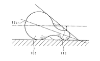
なお実施の形態3におけるボウリングピン1c及び実施の形態4におけるボウリングピン1dは夫々、頭部11c,11dを有するが、球体としての挙動を阻害しないように球体部10c,10dと頭部11c,11dとのバランスが以下に説明する範囲内に収まるように構成されることが好ましい。以下ボウリングピン1cを例に挙げて説明する。図12は、ボウリングピン1cの球体部10cと頭部11cとのバランスを示す説明図である。図12は、ボウリングピン1cの頭部11cがピンデッキ2aに接するようにして倒れている状態を示している。ボウリングピン1cの球体部10cと頭部11cとのバランスは、図12に示すような状態において、頭部11cが球体部10cの中心を通るピンデッキ2aと平行な面(一点鎖線により示されている)よりも上方に出ないような範囲に収まり、破線の矢印で示すように前記水平面との間に適宜間隔を有していることが好ましい。逆に、頭部が球体部の中心を通る水平面よりも上方に出るような破線で示す形状では、ボウリングピンの球体としての挙動が妨げられる。また、ボウリングピン1c同士の衝突が、頭部11c同士又は球体部10c及び頭部10c間で生じる可能性が高まり、従来のボウリングピンと同様となるために好ましくない。
The
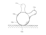
図13は、ボウリングピン1cの球体部10cの動きを示す説明図である。ボウリングピン1cは、頭部11cがレーン(ピンデッキ)に接するまでは球体部10cは図13に示すように球体として挙動する。頭部11cの存在により、実施の形態1及び2のボウリングピン1a,1bのような球体同等の挙動は不可能であるが、頭部11cがピンデッキ2aに接しない場合は球体として挙動するので、動きの予測がし易くなる。実施の形態3及び4におけるボウリング1c,1dの形状はこのように球体としての挙動を可能としつつ、且つ従来のボウリングピンの形状に近いので、プレイヤーに馴染み易く、受け入れられ易い。
FIG. 13 is an explanatory diagram showing the movement of the sphere 10c of the
実施の形態1〜4で示したボウリングピン1a〜1dは、ピンデッキ2a上に図2に示した如く任意の態様に並置されるべく、後述するピンセッターで搬送することが可能なように磁性体が埋め込まれていることが望ましい。例えばボウリングピン1aの場合、球面上に偏りなく磁性体が形成されているとよい。又は球体の中心から離れた一箇所に磁性体が埋め込まれているとよい。ボウリング1bの場合、底部12bの反対側の球面近くに磁性体が埋め込まれているとよい。
The bowling pins 1a to 1d shown in the first to fourth embodiments are magnetic so that they can be transported by a pin setter, which will be described later, in order to be juxtaposed in an arbitrary manner on the
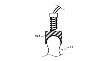
ボウリングピン1cの場合、頭部10cの内部に磁性体が埋め込まれているとよい。図14は、ボウリングピン1cの内部を示す縦断面図である。図14に示す如く、ボウリング1cは頭部10cよりも小径の略球体状の磁性体14cが、頭部10cと略同心となるように埋め込まれている。図15は、ボウリングピン1cの内部の他の一例を示す縦断面図である。図15に示す如くボウリングピン1cは、頭部10cに磁性体からなるネジ16cが、ボウリングピン1cの中心軸と同一方向に底部12c側に向けてねじ込まれて構成されてもよい。この場合、ネジ16cは頭頂部が頭部10cの形状に沿うような曲面をなしている。このようにボウリングピン1cに磁性体14c又はネジ16cが埋め込まれている場合、磁石によってボウリングピン1cを吊り上げて搬送が可能になる。なお図14の縦断面図に示す如く、ボウリングピン1cは内部に空洞15cを有していてもよい。これにより、ボール3又は他のボウリングピン1cと衝突した際に、衝突音を響かせることが出来る。
In the case of the
ボウリングピン1dの場合も、図14及び図15に示すように頭部10dに磁性体が埋め込まれているとよい。なおボウリングピン1dの場合は頭部11dに平坦部13dが設けられているから、ネジの頭頂部は平坦面をなしているとよい(図16参照)。
Also in the case of the bowling pin 1d, it is preferable that a magnetic material is embedded in the
(実施の形態5)
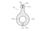
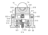
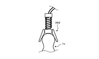
図16は、実施の形態5におけるボウリングピンを示す縦断面図である。実施の形態5におけるボウリングピン1eの形状は、ボウリングピン1dと同様であるから詳細な説明を省略する。実施の形態5におけるボウリングピン1eは、頭部11eに磁性体からなるネジ16eが、ボウリングピン1eの中心軸と同方向に底部12e側に向けてねじ込まれて構成されている。ネジ16eは、頭部11eの形状に沿うように頭頂部が平坦面をなしており、実施の形態4におけるボウリングピン1dの平坦部13d同様の平坦部13eを形成している。またボウリングピン1eは、球体部10e内部に空洞15eを有し、空洞15eは底部12eに設けられている縦方向の孔17eに連通している。底部12eに設けられた孔17eは、ボウリングピン1dを設置する所定の箇所に突起部を設けた場合に突起部が内部に入ることが可能に構成されてあり、これによってボウリングピン1eを所定の箇所に並置した場合に安定する。
(Embodiment 5)
FIG. 16 is a longitudinal sectional view showing a bowling pin in the fifth embodiment. Since the shape of the bowling pin 1e in the fifth embodiment is the same as that of the bowling pin 1d, detailed description thereof is omitted. The bowling pin 1e according to the fifth embodiment is configured such that a screw 16e made of a magnetic material is screwed toward the bottom 12e in the same direction as the central axis of the bowling pin 1e. The screw 16e has a flat top surface along the shape of the
(実施の形態6)
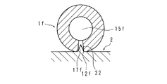
図17は、実施の形態6におけるボウリングピン1fを示す縦断面図である。実施の形態6におけるボウリングピン1fの形状は、ボウリングピン1bと同様であるので、詳細な説明は省略する。実施の形態6におけるボウリングピン1fは、内部に球体と略同心の球状の空洞15fを有し、底部12fに設けられている縦方向の孔17fに連通している。底部12fに設けられた孔17fは、ボウリングピン1fを設置する所定の箇所に突起部22を設けた場合に、突起部22が内部に入ることが可能に構成されてあり、これによってボウリングピン1fを所定の箇所に並置した場合に安定する。
(Embodiment 6)
FIG. 17 is a longitudinal sectional view showing the bowling pin 1f according to the sixth embodiment. Since the shape of the bowling pin 1f in the sixth embodiment is the same as that of the bowling pin 1b, detailed description thereof is omitted. The bowling pin 1f according to the sixth embodiment has a spherical cavity 15f that is substantially concentric with a sphere and communicates with a
実施の形態1〜6に示したようなボウリングピン1a〜1fを用いたボウリングでは、ピンデッキ2a上に任意の態様で並置された複数のボウリングピン1a〜1fに対し、レーン2の始端に接続されているアプローチからプレイヤーがボール3を投げて実施する。ボール3の投球回数は、従来のボウリングのように1フレームにつき最大2又は3回であってもよく、1フレーム1回であってもよい。従来のボウリングのように1ゲームに10フレーム分投球するようにしてもよいし、設定される難易度に応じてより少ない数のフレーム分だけ投球するようにしてもよい。このとき1フレームずつ、ボウリングピン1a〜1fを任意の態様で並置するが、各フレームで並置態様を変更しても、同一の並置態様としてもよい。1フレームで2〜3回の複数回投球させる場合には、2回目以降のボウリングピン1a〜1fの並置は、1回目で各ボウリングピン1a〜1fに対して“倒れた”のか否かの判定が必要であり、更に“倒れて”いないボウリングピン1a〜1fを残すように、“倒れた”ボウリングピン1a〜1fがピンデッキ2aから取り除かれる必要がある。
In the bowling using the bowling pins 1a to 1f as shown in the first to sixth embodiments, the plurality of bowling pins 1a to 1f juxtaposed in an arbitrary manner on the
このように一部又は全部が球体であるボウリングピン1a〜1fを使用した球技を実施するためには、以下に示すようなピンセッターが必要になる。ピンセッターは例えば、上述したようにボウリングピン1aの表面又はボウリングピン1a〜1fの内部に磁性体を埋め込むようにし、磁性体を吸い付けることができる電磁石を利用してボウリングピン1a〜1fを例えば数秒以内にピンデッキ2a内の任意の位置に搬送する機構を有するとよい。電磁石を使用しなくとも、頭部11c〜11eを有するボウリングピン1c〜1eを用いる場合には従来のピンセッターのように頭部11c〜11eと球体部10c〜10eとの間のくびれ部分を指示して搬送する搬送部を用い、コンピュータを用いた制御で任意の位置に搬送することが可能である。
Thus, in order to carry out a ball game using the bowling pins 1a to 1f, which are partially or entirely spherical, a pin setter as shown below is required. For example, as described above, the pin setter is configured to embed a magnetic body on the surface of the
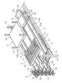
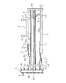
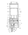
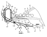
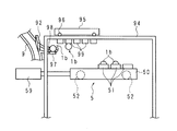
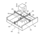
以下、ピンセッターの具体例を、図面を参照して説明する。図18は、ピンセッターの一例を示す斜視図であり、図19は側面図、図20は上面図である。ピンセッターは、実施の形態1〜6に示したボウリングピン1a〜1fのいずれかを、レーン2の終端部のピンデッキ2a上に複数本並置する動作をなし、またレーン2上を転がってピンデッキ2aを通過したボール3、及び該ボール3と衝突したボウリングピン1a〜1fを回収する動作をなす装置であり、搬送部4、溜置部5、排除部6、及び回収部7を備えている。搬送部4、溜置部5及び排除部6は後述する制御機構により制御される。
Hereinafter, specific examples of the pin setter will be described with reference to the drawings. 18 is a perspective view showing an example of a pin setter, FIG. 19 is a side view, and FIG. 20 is a top view. The pin setter operates to place any one of the bowling pins 1a to 1f shown in the first to sixth embodiments on the
図18に示す如く、レーン2の終端部には長手方向に伸びるガイドフレーム40がレーン2の幅方向両側に設けてある。これらのガイドフレーム40は、上下に間隔を隔てて並ぶ各2本のガイドレール40a,40bを備えており、上に位置するガイドレール40aには溜置部5が、また下に位置するガイドレール40bには排除部6が、夫々に沿って移動可能に支持されている。
As shown in FIG. 18, guide frames 40 extending in the longitudinal direction are provided at both ends in the width direction of the
搬送部4は、扁平な直方体状をなす支持盤42と、支持盤42の四隅を指示する吊下棒41とを備える。吊下棒41はピンデッキ2aの上方を覆う図示しない天井部から垂下されている。支持盤42は、吊下棒41の昇降により、ピンデッキ2aに近接対向する加工位置と、溜置部5のレーン2長手方向の移動域よりも上方の上昇位置との間で昇降可能である。支持盤42については詳細を後述する。
The
溜置部5は、扁平な直方体状をなす運搬台50と、該運搬台50上で移動する複数の移動車51を備える。運搬台50は、前述したガイドレール40a,40a間に架け渡され、夫々に転接する各一対の車輪52(図19参照)を介して支持されている。運搬台50の一側は、複動式の油圧シリンダ59の出力ロッドによってレーン2の長さ方向に移動することが可能である。運搬台50の上面には、レーン2の幅方向に複数の矩形溝が設けられており、該矩形溝には夫々、1又は複数の移動車51が収容されている(図18〜図20では一部のみ図示)。移動車51はボウリングピン1a〜1fが載置可能であり、レーン2の幅方向及び上下方向に移動可能である。移動車51については詳細を後述する。
The
排除部6は、底面が開放された扁平な箱状の筐体60と、該筐体60の下方に筐体60内部からアーム612で吊下支持される排除板611とを備える。筐体60は、前述したガイドレール40b,40b間に架け渡され、夫々に転接する各一対の車輪62を介して支持されている。筐体60の一側は、複動式の油圧シリンダ69の出力ロッドによってレーン2の長さ方向に移動することが可能である。
The
回収部7は、ガイド壁71、ベルトコンベヤ70、上昇機8及びレール9を備える。ベルトコンベア70は、レーン2の終端から延設される傾斜面21よりも更に奥側(図18〜20では手前)に、更に奥側にベルトが動くように設置される。上昇機8は、上下方向に回転するように架け渡されるベルト80と、ベルト80の外周に所定間隔を置いて設けられている複数のアーム81とを有し、ベルトコンベア70よりも更に奥側(図18〜20では手前)に設置される。ベルト80の高さは、ガイドフレーム40上の溜置部5よりも高い。そしてベルト80は、ベルトコンベア70側が上昇し反対側が下降するようにして回転する。更に上昇機8はベルトコンベア70の先端に沿うように、上昇するアーム81にボウリングピン1a〜1f及びボール3を導くガイド82を有している。ガイド壁71は、レーン2上のピンデッキ2aからベルトコンベア70、及びガイド82に至るまでの範囲の側部に沿ってボウリングピン1a〜1f及びボール3をガイド82へ導くように設けられている。レール9は、上昇機8のベルトコンベア70とは反対側の頂点付近から、溜置部5上方、ベルトコンベア70の上方及びボール3の回収部各々へ分岐しながら滑らかに下降するように設けられている(図示せず)。
The
次に、搬送部4、溜置部5、排除部6及び回収部7について詳細に説明する。図21は、搬送部4のレーン2側(下側)からの斜視図である。図21に示すように支持盤42のレーン2側の広面には、各々オン(励磁)/オフの制御が可能な電磁石43がマトリクス状に設けられている。電磁石43の大きさは夫々、ボウリングピン1a,1b,1f、又はボウリングピン1c〜1eの球体部10c〜10eの最大径よりも小さくてよい。小さくても強力な電磁石43を使用することにより、並置態様の自由度が上がる。なお各電磁石43には、電磁石43にボウリングピン1a〜1fが支持されているか否かを判定するためのセンサ44が備えられている。
Next, the
溜置部5の運搬台50には、上述したように複数の移動車51が収容されている。図22は、移動車51の模式側面図、図23は図22のA−A´線による模式断面図である。図22及び図23では、ボウリングピン1aが載置されている状態で図示している。移動車51は、運搬台50におけるレーン2の幅方向の移動及び上下移動を実現する駆動部511を有する。駆動部511は、運搬台50の矩形溝の底部に、矩形溝の方向に沿って2本設けられているラック501夫々に噛合う各一対のギア513と、矩形溝の側壁に設けられたガイド溝502に対応する突出部512とを有する。駆動部511は、ギア513と噛合ってこれを回転させる小さなギア516とギア516を回転させるモータ515と、載置台510を昇降ガイド519に沿って上下に駆動させるギア518、ギア518を回転させるモータ517、ギア518が噛合って上下に動くネジ軸514とを備える。突出部512は、ガイド溝502に設けられた信号線と電気的に接続する端子を有し、駆動部511内部のモータ515,517へ駆動電力を供給すると共に、後述する制御機構からの制御信号を伝達するようにしてもよい。これにより、移動車51の運搬台50上における動作が制御される。
As described above, a plurality of
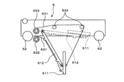
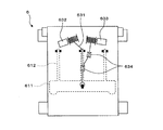
排除部6は、吊下支持される排除板611を内部に収容したり排出したりすることが可能である。図24は、排除部6の模式側面図であり、図25は、排除部6の模式下面図である。排除部6は図24,25に示す如く、アーム612に軸支される排除板611と、排除板611及びアーム612に夫々一端が固定されているワイヤ631,631と、一方のワイヤ631の他端側をアーム612側に巻き取る巻取器632と、他方のワイヤ631の他端側を筐体60内部側に巻き取る巻取器633とを備える。排除板611の平面視した場合、図25に示す如く外縁部がガータレーンを含むレーン2の断面形状に沿うような形をなす。
The
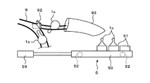
図26及び図27は、回収部7のレール9を模式的に示す説明図である。回収部7のレール9の分岐点手前には、通過するボール3及びボウリングピン1a〜1f夫々の重量が所定値以上か否かを判定するセンサ106が設けられている。またレール9の1つ目の分岐点にはボール3とボウリングピン1a〜1fとを仕分ける仕分扉91を備え、2つ目の分岐点には溜置部5へ導くか又はベルトコンベア70へ再度戻すかを仕分ける仕分扉92を備える。また図27に示すように、レール9の先端部には、ボウリングピン1a〜1fの姿勢を整えるガイド93を備える。なおガイド93内部には図示しないストッパーを有し、ガイド93からのボウリングピン1a〜1fの排出の有無を制御する。なお図26及び図27では、頭部11cを有するボウリングピン1cを用いる場合が示されている。
26 and 27 are explanatory views schematically showing the
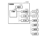
上述のように構成されるピンセッターの動作について説明する。図28は、ピンセッターの動作を制御する制御機構100の構成を示すブロック図である。制御機構100は、制御部101、記憶部102、一時記憶部103、入力部104及び出力部105を備える。制御部101は例えばCPU(Central Processing Unit )を用いる。記憶部102は例えばフラッシュメモリを用い、制御部101が読み出すプログラム、制御条件等を書き換え可能に記憶する。一時記憶部103は例えばDRAM(Dynamic Random Access Memory)のようなランダムメモリを用い、制御部101の処理により生成される情報を一時的に記憶する。入力部104は、後述するセンサ44及びセンサ106からの信号を入力する。出力部105は、搬送部4、溜置部5、排除部6及び回収部7へ制御信号を出力する。
The operation of the pin setter configured as described above will be described. FIG. 28 is a block diagram showing the configuration of the
制御機構100により、制御される各構成部の動作について夫々詳細に説明する。搬送部4の支持盤42は上昇位置で待機し、溜置部5の運搬台50はガイドレール40aの最も奥側で待機し、排除部6の筐体60もガイドレール40bの最も奥側で待機している。まず前述の図26及び図27を参照し、ボウリングピン1a〜1fが溜置部5に溜め置かれるまでの動作について説明する(図26及び図27ではボウリングピン1cが図示されている)。ベルトコンベヤ70及びガイド壁71によってガイド82へ導かれたボウリングピン1a〜1fは、球体部10cがアーム81に支持されるようにして上昇機8により上昇する。ボウリングピン1a〜1fは、上昇機8の頂点に達したときに自重によりアーム81からレール9へ転がり出る。ボウリングピン1a〜1fは、レール9上を球体として転動、滑動することで進む。分岐点手前のセンサ106にて、通過した物体の重量が所定値以上であるか否かが判定され、センサ106から出力される検出信号を入力する制御機構100は、検出信号に基づき制御部101の処理によってボウリングピン1a〜1fとボール3とを判別し、仕分扉91の開閉を制御する制御信号を出力する。これにより、ボール3はボール回収部へ導かれ、プレイヤーの手元に戻る。
The operation of each component controlled by the
制御機構100の制御部101は、レール9の先端部のストッパーにてボウリングピン1a〜1fを各停止させながら、空き状態の移動車51がガイド93の先端の下方に来るように、油圧シリンダ59及び移動車51のモータ515の作動を制御する。空き状態の移動車51がガイド93の先端下方に来た場合、制御部101はこれを検知して移動車51のモータ515を停止させてレーン2の幅方向の移動を停止させ、次にモータ517を作動させて上昇させる。移動車51の載置台510が所定の高さまで上昇したときに載置台510の上昇を停止させ、ストッパーを開放してボウリングピン1a〜1fを1つ載置させ、ストッパーを再び閉める。載置台510にボウリングピン1a〜1fが載置されたことが載置台510内部のセンサ等で検知された場合、制御部101は載置台510を下降させ、次のピンデッキ2aへの配置位置に対応する位置へ移動車51を移動させる。1つのボウリングピン1a〜1fを移動車51に載置させている間、制御部101は、仕分扉92を閉じて、ボウリングピン1cを再度ベルトコンベア70へ戻すようにしてもよい。なお、載置台510にボウリングピン1a〜1fを載置させるに際し、載置台510を昇降させることなくストッパーの開閉にてボウリングピン1a〜1fを載置台510に載置させることが可能なように、レール9及びガイド93の高さを設計するようにしてもよい。
The
制御機構100の制御部101は、移動車51の動作、仕分扉92、及びレール9の先端のストッパーを制御してボウリングピン1a〜1fを溜置部5の運搬台50上に配置する。このとき制御部101は、次のボウリングピン1a〜1fのピンデッキ2a上の並置態様に対応するような態様で矩形状の運搬台50上に並置されるように、移動車51の位置を制御する。制御部101は、移動車51の位置を制御した後、油圧シリンダ59のロッドを出力させて、上昇位置で待機している搬送部4に対向するように運搬台51を移動させる。
The
次に制御部101は、次のボウリングピン1a〜1fの並置態様を決定する。そして制御部101は、上昇位置で待機している搬送部4の吊下棒41を下降させて支持盤42が運搬台50に近接対向する位置で停止させる。なおこのとき、支持盤42を下降させるのではなく運搬台50上の各移動車51の載置台510を所望の位置にて上昇させるようにしてもよい。制御部101は、決定した並置態様に対応する電磁石43を決定する。このとき並置させるボウリングピン1a〜1fの数は“10”に限らず、並置可能な範囲で任意に決定してよい。マトリクス状に設けられた電磁石43を用いて適宜オン/オフを制御することにより、ボウリングピン1a〜1fのいずれについても、レーン2上に正三角形以外の任意の位置に並置することが可能である。制御部101は、決定させた電磁石43を励磁させ、励磁された電磁石43によってボウリングピン1a〜1fが支持される。制御部101は、支持盤42を上昇位置まで上昇させて待機させる。このとき制御部101は、移動車51へのボウリングピン1a〜1fの載置、移動車51の配置、搬送部4下への移動、支持盤42の下降、及び電磁石43の励磁によるボウリングピン1a〜1fの支持の動作は、1回の並置動作に対して複数回に分けて行なうようにしてもよい。
Next, the
次に制御部101は、油圧シリンダ59のロッドを引き込んで運搬台50をガイドレール40aの奥側に移動させる。制御部101は、搬送部4の支持盤42を上昇位置からピンデッキ2aに近接対向する下降位置まで下降させる。制御部101は、支持盤42が支持しているボウリングピン1a〜1fがピンデッキ2a上に安定的に接触した状態を検知した場合に、支持盤42の電磁石43の励磁をオフにし、上昇位置まで上昇させ、待機させる。制御部101は、ボウリングピン1a〜1fの決定している並置態様を記憶している。
Next, the
レーン2上に並置されたボウリングピン1a〜1fは、プレイヤーによって投擲されたボール3と衝突し、ピンデッキ2a外に転がり出るか、又は所定の距離以上動くか、又は文字通り倒れることで“倒数”として計数される。“倒数”としてカウントされるケースは、ボウリングピン1a〜1fの種類によって異なる。頭部を有さないボウリング1a,1b,1fの場合、ボウリングピン1a,1b,1fが最初に並置された位置から動いた場合、倒れたと扱われてもよい。この場合、ピンデッキ2a全体を撮影範囲に含むように設置されたカメラを用いて倒数をカウントしてもよいし、複数の電磁石43に各対応するように設けられたセンサ44を用いてもよい。センサ44を用いる場合制御部101は、プレイヤーによる投球がなされた後、支持盤42を下降位置まで下降させ、記憶している並置態様に対応する電磁石43を励磁させ、支持盤42を少し上昇させる。このときセンサ44にて、ボウリングピン1a,1b,1fが支持されたと判定されたもの以外は、“倒数”としてカウントされる。ボウリングピン1a,1b,1fがピンデッキ2a外へ転がり出た場合に、制御部101が倒れたと扱うようにしてもよい。この場合、制御部101は、カメラ等でピンデッキ2a内に残っているボウリングピン1a,1b,1fを認識し、認識したボウリングピン1a,1b,1fの数を計数する。また、頭部11c〜10eを設けたボウリングピン1c〜1eの場合、従来のボウリングピンのように、底部12c〜12eで自立していない場合に倒れたとして扱う。ボール3が通過した後に下降させた電磁石43に支持されたボウリングピン1c〜1e以外は倒れたとして扱われる。
The bowling pins 1a to 1f juxtaposed on the
1つのフレームにて複数回投球させる場合、1回毎に、倒れていないボウリングピン1a〜1fは支持盤42の電磁石43で支持し、その間に後述する排除部6でレーン2上のボール3及びボウリングピン1a〜1fを排除する。最後の投球がなされた後は、制御部1010はカメラにて撮影された画像に基づいて“倒数”をカウントしてもよいし、支持盤42上のセンサ44を使用して“倒数”をカウントしてもよい。
When throwing a plurality of times in one frame, each time the bowling pins 1a to 1f that are not tilted are supported by the
レーン2に残っているボウリングピン1a〜1fを排除する排除部6の動作について説明する。制御部101は、ボール3がピンデッキ2a上に到達した後、油圧シリンダ69を制御して筐体60をガイドレール40bのピンデッキ2a側の端部(始端)まで移動させる。制御部101は、筐体60がガイドレール40aの始端側に到達したと判断した場合、巻取器632を作動させてアーム612及び排除板611を排出させる。排除板611は、外周がレーン2の断面形状に沿う位置となるように吊下支持される。制御部101は、排除板611が吊下支持されている状態を保持したまま、油圧シリンダ69のロッドを引き込んで筐体60をガイドレール40bの終端まで移動させる。これにより、レーン2上のボール3及びボウリングピン1a〜1fがレーン2の終端まで掻き寄せられ、傾斜板21を転がり落ちてベルトコンベア70まで集められる。
The operation of the
このように一部又は全部が球体であるボウリングピン1a〜1fを用いた球技を実現する球技装置が構成され、これによってゲーム性が高い球技を楽しむことが可能となる。上述したように、ボウリングピン1a〜1fは球体として挙動するので、挙動の予測が容易であり、更に、ボウリングピン1a〜1fの並置態様は従来のボウリングのような10本を平面視正三角形状とすることに限られないので、投球毎に難易度を変更したり、投球数を変更したりすることができ、高技術者と低技術者、プロ競技者と観覧者などが共に球技を楽しむことが可能となる。 In this way, a ball game apparatus that realizes a ball game using the bowling pins 1a to 1f, which are partially or entirely spheres, is configured, and this makes it possible to enjoy a ball game with high game performance. As described above, since the bowling pins 1a to 1f behave as spheres, it is easy to predict the behavior, and the juxtaposition of the bowling pins 1a to 1f is a regular triangle shape in plan view as in the conventional bowling. Therefore, you can change the difficulty level or change the number of pitches for each pitch, and both high and low technicians, professional athletes and viewers can enjoy ball games together. It becomes possible.
球技装置は上述した構成に限られない。例えば以下のような構成としてもよい。
図29は、回収部7のレール9の先端部の他の態様を示す説明図である。図29では、ボウリングピン1bを用いる場合の態様を示す。ボウリングピン1bを用いる場合、磁性体が埋め込まれている箇所を上部として移動車51に載置されることが求められるから、磁性体が埋め込まれている箇所を上部とするような機構が必要である。したがって、図29に示す如く、図27に示したガイド93に代替して、レール9の先端部に、レーン2の長さ方向に沿う方向に設けられる1対のフレーム94と、フレーム94間に架け渡され、夫々に転接する車輪96を介して支持される移動車95と、移動車95の下部に設けられる電磁石99と、レール9の先端部でボウリングピン1bを転動させるローラ97,98とで構成されている。フレーム94の高さは溜置部5よりもボウリングピン1bの大きさ分以上高い。フレーム94間の距離は、ボウリングピン1bの径よりも少し位大きいくらいでよい。レール9の先端部に到達したボウリングピン1bは、ローラ97,98により縦横に転動させられ、移動車95の移動によって近接した電磁石99と反応する箇所が上部に来たときに、電磁石99に吸い寄せられて吊持される。吊持されたボウリングピン1bは、移動車95の移動によって溜置部5の上方へ運ばれる。制御機構100の制御部101が、載置台510を上昇させたところで、ボウリングピン1bを吊持している電磁石99をオフとすることで移動車51の載置台510上にボウリングピン1bを載置させることができる。このように、略球体であるボウリングピン1bを使用する場合であっても、レール9から溜置部5へ適切に導くことが可能である。図29に示した構成は、完全球体のボウリングピン1aを、表面ではなく表面近くの一箇所に磁性体を埋める構成とした場合、及びボウリングピン1fにも適用できる。なおボウリングピン1fを用いる場合、底部12fに設けた孔17fを探索するようにして底部12fから移動車51の載置台510に載置させるようにしてもよい。
The ball game apparatus is not limited to the configuration described above. For example, the following configuration may be used.
FIG. 29 is an explanatory view showing another aspect of the tip end portion of the
図30は、搬送部4の他の態様を示すレーン側(下側)からの斜視図であり、図31は、図30の一部を拡大した拡大図である。他の態様において搬送部4は、支持盤42の底部を複数の枠44に区切り、各枠内で縦横に動くことが可能に構成された電磁石45を用いる。なお図30,31では、ボウリングピン1bを用いる場合の態様が示されている。他の態様における搬送部4では、各枠44に縦横に架け渡したラック46の内の下側のラック46に電磁石45を取り付け、図31に示す如く、ラック46を挟み込むようにして電磁石45にカバー47が固定されている。カバー47には2対のギア48がラック46の高さに対応する位置で回転可能に支持されている。電磁石45とカバー47とが一体となった際に、2対のギア48は夫々ラック46に噛合うように構成されている。なおカバー47には図示しないモータが備えられており、2対のギア48を1対ずつ回転制御できるようにしてある。ラック46の両端には夫々、該ラック46を軸にして回転する車輪49が取り付けられている。これにより枠44内で電磁石45の位置を縦横に自由に移動させることができる。この態様では電磁石45の数を節約することが可能である。
FIG. 30 is a perspective view from the lane side (lower side) showing another aspect of the
図32は、溜置部5の運搬台50を動かす機構の他の態様を示す模式斜視図である。図18〜図20、図27に示した運搬台50の例では、溜置部5は油圧シリンダ59によりレーン2の長さ方向に移動する構成とした。しかしながらこれに限らず、図32に示す如く、ガイドフレーム40の横架材をラックで構成し、運搬台50の車輪をラックに噛合うように構成し、運搬台50の両端部夫々にワイヤ58,58を固定し、ワイヤ58,58のいずれを巻取器57にて巻き取るかを制御機構100によって制御して運搬台50を移動させる構成としてもよい。
FIG. 32 is a schematic perspective view showing another aspect of the mechanism for moving the
図33は、搬送部4にて使用される電磁石の形状の一例を模式的に示す断面図であり、図34は、他の一例を模式的に示す断面図である。図33及び図34の例では、ボウリングピン1cを使用した場合の構成が示されている。図33及び図34における太い実線は、導線及びコイルを示している。図33に示す例では、支持盤42に設けられる電磁石341は一面がボウリングピン1cの頭部11cに対応する半球状の凹面をなす直方体状をなす。また、図34に示す例では、支持盤42に設けられる電磁石342はボウリングピン1cの頭部11cを把持する可動アームの形状を有して構成されている。
FIG. 33 is a cross-sectional view schematically showing an example of the shape of the electromagnet used in the
なお、上述のように開示された本実施の形態はすべての点で例示であって、制限的なものではないと考えられるべきである。本発明の範囲は、上記した意味ではなく、特許請求の範囲によって示され、特許請求の範囲と均等の意味および範囲内でのすべての変更が含まれることが意図される。 It should be understood that the embodiment disclosed above is illustrative in all respects and not restrictive. The scope of the present invention is defined by the terms of the claims, rather than the meanings described above, and is intended to include any modifications within the scope and meaning equivalent to the terms of the claims.
1a,1b,1c,1d,1e,1f ボウリングピン(被衝突体)
14c 磁性体
2 レーン(経路)
2a ピンデッキ(並置領域)
3 ボール(投擲される球)
4 搬送部
43,431,432 電磁石
5 溜置部
100 制御機構(決定部)
101 制御部(決定部)
1a, 1b, 1c, 1d, 1e, 1f Bowling pins (impacts)
14c
2a Pin deck (arranged area)
3 balls (thrown ball)
4 Conveyance part 43,431,432 Electromagnet 5
101 Control unit (decision unit)
Claims (4)
前記複数の被衝突体の夫々は、一部又は全部が球体からなる
ことを特徴とする球技装置。 A path on which the thrown ball rolls, a plurality of collided objects that are juxtaposed in the juxtaposed area on the path and collided by the spheres, and a juxtaposing device that juxtaposes the collided objects in the juxtaposed area. Including ball game equipment,
Each of the plurality of impacted bodies is partially or entirely made of a sphere.
前記複数の被衝突体を溜め置く溜置部と、
前記複数の被衝突体を支持して前記並置領域へ搬送する搬送部と、
矩形領域である前記並置領域内の任意の位置に前記複数の被衝突体が並置されるよう前記搬送部による搬送先を決定する決定部と
を備えることを特徴とする請求項1に記載の球技装置。 The juxtaposition device comprises:
A storage section for storing the plurality of impacted bodies;
A transport unit that supports the plurality of collided bodies and transports them to the juxtaposed region;
The ball game according to claim 1, further comprising: a determining unit that determines a transport destination by the transport unit so that the plurality of collided objects are juxtaposed at an arbitrary position in the juxtaposed region that is a rectangular region. apparatus.
前記搬送部は電磁石を備える
ことを特徴とする請求項2に記載の球技装置。 The collision object includes a magnetic material,
The ball game apparatus according to claim 2, wherein the transport unit includes an electromagnet.
前記溜置部は、前記搬送部の前記マトリクスに対応する矩形状の範囲内に前記複数の被衝突体を並べて溜め置くようにしてあり、
前記決定部は、前記複数の電磁石の内から励磁させる電磁石を決定するようにしてある
ことを特徴とする請求項2に記載の球技装置。 The transport unit includes a plurality of electromagnets arranged in a matrix, and transports the plurality of impacted objects simultaneously,
The storage unit is configured to store the plurality of collided bodies side by side within a rectangular range corresponding to the matrix of the transport unit,
The ball game apparatus according to claim 2, wherein the determining unit determines an electromagnet to be excited from among the plurality of electromagnets.
Priority Applications (2)
| Application Number | Priority Date | Filing Date | Title |
|---|---|---|---|
| JP2015000441A JP6484034B2 (en) | 2015-01-05 | 2015-01-05 | Ball equipment |
| PCT/JP2015/085897 WO2016111171A1 (en) | 2015-01-05 | 2015-12-23 | Ball game apparatus |
Applications Claiming Priority (1)
| Application Number | Priority Date | Filing Date | Title |
|---|---|---|---|
| JP2015000441A JP6484034B2 (en) | 2015-01-05 | 2015-01-05 | Ball equipment |
Publications (2)
| Publication Number | Publication Date |
|---|---|
| JP2016123728A true JP2016123728A (en) | 2016-07-11 |
| JP6484034B2 JP6484034B2 (en) | 2019-03-13 |
Family
ID=56355871
Family Applications (1)
| Application Number | Title | Priority Date | Filing Date |
|---|---|---|---|
| JP2015000441A Expired - Fee Related JP6484034B2 (en) | 2015-01-05 | 2015-01-05 | Ball equipment |
Country Status (2)
| Country | Link |
|---|---|
| JP (1) | JP6484034B2 (en) |
| WO (1) | WO2016111171A1 (en) |
Families Citing this family (1)
| Publication number | Priority date | Publication date | Assignee | Title |
|---|---|---|---|---|
| FR3117041B1 (en) * | 2020-12-07 | 2022-11-25 | Orange | Connected bowling game |
Citations (4)
| Publication number | Priority date | Publication date | Assignee | Title |
|---|---|---|---|---|
| JPS63122479A (en) * | 1986-11-12 | 1988-05-26 | 松本 正夫 | Balling game apparatus |
| US5562549A (en) * | 1992-01-21 | 1996-10-08 | Nsm Aktiengesellschaft | Automatic bowling alley |
| JPH08511456A (en) * | 1993-06-18 | 1996-12-03 | メンデス・インコーポレーテッド | Automatic pinsetter |
| JP2000312737A (en) * | 1998-12-11 | 2000-11-14 | Tele Systems:Kk | Bowling pin arrangement control device and its connecting unit |
-
2015
- 2015-01-05 JP JP2015000441A patent/JP6484034B2/en not_active Expired - Fee Related
- 2015-12-23 WO PCT/JP2015/085897 patent/WO2016111171A1/en not_active Ceased
Patent Citations (4)
| Publication number | Priority date | Publication date | Assignee | Title |
|---|---|---|---|---|
| JPS63122479A (en) * | 1986-11-12 | 1988-05-26 | 松本 正夫 | Balling game apparatus |
| US5562549A (en) * | 1992-01-21 | 1996-10-08 | Nsm Aktiengesellschaft | Automatic bowling alley |
| JPH08511456A (en) * | 1993-06-18 | 1996-12-03 | メンデス・インコーポレーテッド | Automatic pinsetter |
| JP2000312737A (en) * | 1998-12-11 | 2000-11-14 | Tele Systems:Kk | Bowling pin arrangement control device and its connecting unit |
Also Published As
| Publication number | Publication date |
|---|---|
| JP6484034B2 (en) | 2019-03-13 |
| WO2016111171A1 (en) | 2016-07-14 |
Similar Documents
| Publication | Publication Date | Title |
|---|---|---|
| US7731587B2 (en) | Prize game apparatus | |
| CN101388127B (en) | game currency game device | |
| US10653970B2 (en) | User controllable marble run kit | |
| US20230241472A1 (en) | Entertainment systems and related methods | |
| JP7670611B2 (en) | Interactive maze attraction system and method | |
| US12115425B1 (en) | Standalone and multigame miniature golf structure | |
| EP4520408B1 (en) | Standalone and multigame miniature golf structure | |
| JP6484034B2 (en) | Ball equipment | |
| JP5813348B2 (en) | GAME MEDIUM, AND GAME MACHINE COMPRISING THE GAME MEDIUM | |
| JP4756067B2 (en) | Game machine | |
| JP6196401B1 (en) | Device for discharging the sphere intermittently | |
| KR101149301B1 (en) | Bowling game machine | |
| JP2021502204A (en) | Equipment and methods for arranging at least one bowling pin | |
| US5332217A (en) | Pinball game with moveable track mechanism | |
| KR101917814B1 (en) | Alccagi game apparatus | |
| KR102632853B1 (en) | Bowling apparatus | |
| JP4895987B2 (en) | game machine | |
| US11911706B2 (en) | Automated runway loop for aerial projectile | |
| US2045217A (en) | Game apparatus | |
| JP2021010423A (en) | Game machine | |
| KR102769687B1 (en) | Bowling apparatus | |
| JP7071947B2 (en) | Pachinko machine | |
| JP2012245383A (en) | Token pusher game device | |
| JP2002119634A (en) | Bowling machine using billiard balls | |
| JP4919989B2 (en) | Game moving body moving device and game machine |
Legal Events
| Date | Code | Title | Description |
|---|---|---|---|
| A621 | Written request for application examination |
Free format text: JAPANESE INTERMEDIATE CODE: A621 Effective date: 20171127 |
|
| A131 | Notification of reasons for refusal |
Free format text: JAPANESE INTERMEDIATE CODE: A131 Effective date: 20180925 |
|
| A521 | Request for written amendment filed |
Free format text: JAPANESE INTERMEDIATE CODE: A523 Effective date: 20181106 |
|
| TRDD | Decision of grant or rejection written | ||
| A01 | Written decision to grant a patent or to grant a registration (utility model) |
Free format text: JAPANESE INTERMEDIATE CODE: A01 Effective date: 20190205 |
|
| A61 | First payment of annual fees (during grant procedure) |
Free format text: JAPANESE INTERMEDIATE CODE: A61 Effective date: 20190215 |
|
| R150 | Certificate of patent or registration of utility model |
Ref document number: 6484034 Country of ref document: JP Free format text: JAPANESE INTERMEDIATE CODE: R150 |
|
| LAPS | Cancellation because of no payment of annual fees |