JP2016122002A - Display - Google Patents

Display Download PDF

Info

Publication number
JP2016122002A
JP2016122002A JP2015246365A JP2015246365A JP2016122002A JP 2016122002 A JP2016122002 A JP 2016122002A JP 2015246365 A JP2015246365 A JP 2015246365A JP 2015246365 A JP2015246365 A JP 2015246365A JP 2016122002 A JP2016122002 A JP 2016122002A
Authority
JP
Japan
Prior art keywords
display
display surface
display device
symbol
image
Prior art date
Legal status (The legal status is an assumption and is not a legal conclusion. Google has not performed a legal analysis and makes no representation as to the accuracy of the status listed.)
Granted
Application number
JP2015246365A
Other languages
Japanese (ja)
Other versions
JP6646431B2 (en
Inventor
順雄 藤田
Yorio Fujita
順雄 藤田
孝郎 金井
Takao Kanai
孝郎 金井
貴之 小川
Takayuki Ogawa
小川  貴之
Current Assignee (The listed assignees may be inaccurate. Google has not performed a legal analysis and makes no representation or warranty as to the accuracy of the list.)
Yazaki Corp
Original Assignee
Yazaki Corp
Priority date (The priority date is an assumption and is not a legal conclusion. Google has not performed a legal analysis and makes no representation as to the accuracy of the date listed.)
Filing date
Publication date
Application filed by Yazaki Corp filed Critical Yazaki Corp
Publication of JP2016122002A publication Critical patent/JP2016122002A/en
Application granted granted Critical
Publication of JP6646431B2 publication Critical patent/JP6646431B2/en
Active legal-status Critical Current
Anticipated expiration legal-status Critical

Links

Images

Classifications

    • B60K35/60
    • GPHYSICS
    • G09EDUCATION; CRYPTOGRAPHY; DISPLAY; ADVERTISING; SEALS
    • G09GARRANGEMENTS OR CIRCUITS FOR CONTROL OF INDICATING DEVICES USING STATIC MEANS TO PRESENT VARIABLE INFORMATION
    • G09G5/00Control arrangements or circuits for visual indicators common to cathode-ray tube indicators and other visual indicators
    • G09G5/12Synchronisation between the display unit and other units, e.g. other display units, video-disc players
    • BPERFORMING OPERATIONS; TRANSPORTING
    • B60VEHICLES IN GENERAL
    • B60KARRANGEMENT OR MOUNTING OF PROPULSION UNITS OR OF TRANSMISSIONS IN VEHICLES; ARRANGEMENT OR MOUNTING OF PLURAL DIVERSE PRIME-MOVERS IN VEHICLES; AUXILIARY DRIVES FOR VEHICLES; INSTRUMENTATION OR DASHBOARDS FOR VEHICLES; ARRANGEMENTS IN CONNECTION WITH COOLING, AIR INTAKE, GAS EXHAUST OR FUEL SUPPLY OF PROPULSION UNITS IN VEHICLES
    • B60K35/00Arrangement of adaptations of instruments
    • B60K35/211
    • B60K35/213
    • B60K35/215
    • B60K35/29
    • GPHYSICS
    • G09EDUCATION; CRYPTOGRAPHY; DISPLAY; ADVERTISING; SEALS
    • G09GARRANGEMENTS OR CIRCUITS FOR CONTROL OF INDICATING DEVICES USING STATIC MEANS TO PRESENT VARIABLE INFORMATION
    • G09G3/00Control arrangements or circuits, of interest only in connection with visual indicators other than cathode-ray tubes
    • G09G3/001Control arrangements or circuits, of interest only in connection with visual indicators other than cathode-ray tubes using specific devices not provided for in groups G09G3/02 - G09G3/36, e.g. using an intermediate record carrier such as a film slide; Projection systems; Display of non-alphanumerical information, solely or in combination with alphanumerical information, e.g. digital display on projected diapositive as background
    • B60K2360/186
    • B60K2360/1868
    • B60K2360/344
    • GPHYSICS
    • G06COMPUTING; CALCULATING OR COUNTING
    • G06FELECTRIC DIGITAL DATA PROCESSING
    • G06F3/00Input arrangements for transferring data to be processed into a form capable of being handled by the computer; Output arrangements for transferring data from processing unit to output unit, e.g. interface arrangements
    • G06F3/14Digital output to display device ; Cooperation and interconnection of the display device with other functional units
    • G06F3/1423Digital output to display device ; Cooperation and interconnection of the display device with other functional units controlling a plurality of local displays, e.g. CRT and flat panel display
    • GPHYSICS
    • G09EDUCATION; CRYPTOGRAPHY; DISPLAY; ADVERTISING; SEALS
    • G09GARRANGEMENTS OR CIRCUITS FOR CONTROL OF INDICATING DEVICES USING STATIC MEANS TO PRESENT VARIABLE INFORMATION
    • G09G2300/00Aspects of the constitution of display devices
    • G09G2300/02Composition of display devices
    • G09G2300/023Display panel composed of stacked panels
    • GPHYSICS
    • G09EDUCATION; CRYPTOGRAPHY; DISPLAY; ADVERTISING; SEALS
    • G09GARRANGEMENTS OR CIRCUITS FOR CONTROL OF INDICATING DEVICES USING STATIC MEANS TO PRESENT VARIABLE INFORMATION
    • G09G3/00Control arrangements or circuits, of interest only in connection with visual indicators other than cathode-ray tubes
    • G09G3/04Control arrangements or circuits, of interest only in connection with visual indicators other than cathode-ray tubes for presentation of a single character by selection from a plurality of characters, or by composing the character by combination of individual elements, e.g. segments using a combination of such display devices for composing words, rows or the like, in a frame with fixed character positions
    • GPHYSICS
    • G09EDUCATION; CRYPTOGRAPHY; DISPLAY; ADVERTISING; SEALS
    • G09GARRANGEMENTS OR CIRCUITS FOR CONTROL OF INDICATING DEVICES USING STATIC MEANS TO PRESENT VARIABLE INFORMATION
    • G09G3/00Control arrangements or circuits, of interest only in connection with visual indicators other than cathode-ray tubes
    • G09G3/20Control arrangements or circuits, of interest only in connection with visual indicators other than cathode-ray tubes for presentation of an assembly of a number of characters, e.g. a page, by composing the assembly by combination of individual elements arranged in a matrix no fixed position being assigned to or needed to be assigned to the individual characters or partial characters

Abstract

PROBLEM TO BE SOLVED: To provide a display capable of obtaining a visual effect for making a display area look relatively large.SOLUTION: A display 1 comprises: a first display surface 11 displaying vehicle information; and a second display surface 12 which is provided to be superimposed on the first display surface 11, which transmits light, which has a pattern 64 drawn to span between an inside of a display area of the first display surface 11 and an outside of the display area along a direction in which the first display surface 11 and the second display surface 12 are stacked, and which can switch over between a display state where the pattern 64 is displayed and a non-display state where the pattern 64 is not displayed, the first display surface 11 and the second display surface 12 displaying information. The display 1 can thereby obtain a visual effect for making the display area look relatively large.SELECTED DRAWING: Figure 1

Description

本発明は、表示装置に関する。   The present invention relates to a display device.

車両等に搭載される従来の表示装置として、例えば、特許文献1には、車両の状態を示す種々の情報が表示される表示領域を備えたディスプレイを備え、ディスプレイの表示領域の一部の上にリング状表示仕切り部材が配置された車両用表示装置が開示されている。この車両用表示装置は、リング状表示仕切り部材の開口部に拡大レンズが取り付けられると共に、当該リング状表示仕切り部材が表示領域上で移動可能に構成されることで、立体感を増したメリハリのある表示を実現している。   As a conventional display device mounted on a vehicle or the like, for example, Patent Document 1 includes a display including a display area on which various information indicating the state of the vehicle is displayed. A vehicle display device in which a ring-shaped display partition member is disposed is disclosed. The vehicular display device has a magnifying lens attached to the opening of the ring-shaped display partition member, and the ring-shaped display partition member is configured to be movable on the display region, thereby improving the stereoscopic effect. A certain display is realized.

特許第4568087号公報Japanese Patent No. 4568087

ところで、上述の特許文献1に記載の車両用表示装置は、例えば、リング状表示仕切り部材の移動がディスプレイの表示領域内に限られるものであり、リング状表示仕切り部材がいずれの位置に移動した場合であっても表示領域の一部が当該リング状表示仕切り部材に隠れてしまう等、表示領域をより大きく見せる点で更なる改善の余地がある。   By the way, in the vehicle display device described in Patent Document 1 described above, for example, the movement of the ring-shaped display partition member is limited to the display area of the display, and the ring-shaped display partition member has moved to any position. Even in such a case, there is room for further improvement in that the display area can be seen larger, such as a part of the display area hidden behind the ring-shaped display partition member.

本発明は、上記の事情に鑑みてなされたものであって、表示領域を相対的に大きく見せる視覚効果を得ることができる表示装置を提供することを目的とする。   The present invention has been made in view of the above circumstances, and an object thereof is to provide a display device capable of obtaining a visual effect that makes a display area relatively large.

上記目的を達成するために、本発明に係る表示装置は、車両情報を表示する第1表示面と、前記第1表示面に重ねて設けられ光を透過すると共に、前記第1表示面との積層方向に沿って視て前記第1表示面の表示領域内と表示領域外とにまたがって描かれた図柄を有し、当該図柄を表示する表示状態と、当該図柄を非表示とする非表示状態とに切り替え可能である第2表示面とを備え、前記第1表示面と前記第2表示面とによって情報を表示することを特徴とする。   In order to achieve the above object, a display device according to the present invention includes a first display surface that displays vehicle information, a light that is provided to overlap the first display surface and transmits light, and the first display surface. Displayed along the display direction of the first display surface as viewed along the stacking direction and having a design drawn across the display region, a display state in which the design is displayed, and non-display in which the design is hidden And a second display surface that can be switched to a state, and information is displayed on the first display surface and the second display surface.

また、上記表示装置では、前記第1表示面と前記第2表示面とは、前記車両情報と前記図柄とを連携させた少なくとも1つの情報を表示するものとすることができる。   In the display device, the first display surface and the second display surface may display at least one information in which the vehicle information and the symbol are linked.

また、上記表示装置では、前記第1表示面は、矩形状の表示領域を含み、前記図柄は、前記第1表示面の矩形状の表示領域内から表示領域外に張り出した円弧状の部分を含むものとすることができる。   In the display device, the first display surface includes a rectangular display region, and the design includes an arc-shaped portion that protrudes from the rectangular display region of the first display surface to the outside of the display region. Can be included.

また、上記表示装置では、前記第1表示面は、前記車両情報として指針の画像を表示し、前記図柄は、前記指針の画像の周りに設けられ当該指針の画像によって指し示される指標部を含んで構成されるものとすることができる。   Further, in the display device, the first display surface displays an image of a pointer as the vehicle information, and the design includes an indicator portion provided around the pointer image and pointed to by the pointer image. It can consist of.

また、上記表示装置では、前記第2表示面は、前記図柄を構成する凹凸部が形成され、光源から照射される光によって前記図柄を表示する前記表示状態と、前記光源が消灯することで前記図柄を非表示とする前記非表示状態とを切り替え可能であるものとすることができる。   Further, in the display device, the second display surface has an uneven portion forming the symbol, the display state in which the symbol is displayed by light emitted from a light source, and the light source is turned off to turn off the light source. It is possible to switch between the non-display state in which the symbols are not displayed.

また、上記表示装置では、前記第1表示面は、一方向に偏光された光によって前記車両情報に関する画像を表示し、前記凹凸部は、前記第2表示面に形成され前記偏向された光の偏光方向と交差する方向に延在する溝であるものとすることができる。   Further, in the display device, the first display surface displays an image related to the vehicle information by light polarized in one direction, and the uneven portion is formed on the second display surface and has the deflected light. It can be a groove extending in a direction crossing the polarization direction.

本発明に係る表示装置は、第1表示面に表示される車両情報と、第1表示面に重ねて設けられ光を透過する第2表示面に表示される図柄とを組み合わせて情報を表示することができる。この場合、表示装置は、第1表示面に重ねて設けられる第2表示面が光を透過し、かつ、図柄の表示、非表示を切り替え可能に構成されることで、第1表示面の表示領域を広く使って車両情報を表示することもできる。そしてさらに、表示装置は、第2表示面の図柄が第1表示面の表示領域内と表示領域外とにまたがるように描かれているので、第1表示面の表示領域外のより広い領域に図柄を表示することができる。この結果、表示装置は、第1表示面の車両情報と第2表示面の図柄とで全体として表示領域を相対的に大きく見せる視覚効果を得ることができる、という効果を奏する。   The display device according to the present invention displays information by combining vehicle information displayed on the first display surface and symbols displayed on the second display surface that are provided on the first display surface and transmit light. be able to. In this case, the display device is configured such that the second display surface provided so as to overlap the first display surface transmits light and is configured to be able to switch between display and non-display of symbols, thereby displaying the first display surface. Vehicle information can also be displayed using a wide area. Further, since the display device is drawn so that the design of the second display surface spans the display area of the first display surface and the outside of the display area, the display device has a wider area outside the display area of the first display surface. A symbol can be displayed. As a result, the display device has an effect that it is possible to obtain a visual effect that makes the display area relatively large as a whole with the vehicle information on the first display surface and the symbols on the second display surface.

図1は、実施形態に係る表示装置の奥行き方向前面側の正面図である。FIG. 1 is a front view of the front side in the depth direction of the display device according to the embodiment. 図2は、図1に示すA−A断面図である。FIG. 2 is a cross-sectional view taken along line AA shown in FIG. 図3は、図1に示すB−B断面図である。3 is a cross-sectional view taken along line BB shown in FIG. 図4は、実施形態に係る表示装置の文字板を表す正面図である。FIG. 4 is a front view illustrating the dial of the display device according to the embodiment. 図5は、実施形態に係る表示装置の透明文字板を表す正面図である。FIG. 5 is a front view illustrating the transparent dial of the display device according to the embodiment. 図6は、図2に示す囲み線C内の部分的な断面図である。FIG. 6 is a partial cross-sectional view taken along the encircling line C shown in FIG. 図7は、実施形態に係る表示装置の第1表示面、及び、第2表示面を含む要部の分解斜視図である。FIG. 7 is an exploded perspective view of a main part including the first display surface and the second display surface of the display device according to the embodiment. 図8は、表示装置の輝度実測試験の前提条件について説明する模式図である。FIG. 8 is a schematic diagram for explaining the preconditions for the luminance measurement test of the display device. 図9は、表示装置の輝度実測試験の前提条件について説明する模式図である。FIG. 9 is a schematic diagram for explaining the preconditions for the luminance measurement test of the display device. 図10は、表示装置の輝度実測試験の前提条件について説明する模式図である。FIG. 10 is a schematic diagram for explaining the preconditions for the luminance measurement test of the display device. 図11は、表示装置の輝度実測試験の結果を表す線図である。FIG. 11 is a diagram showing the result of the brightness measurement test of the display device. 図12は、実施形態に係る表示装置の第2表示面の一部が非表示状態である場合の表示態様の一例を表す正面図である。FIG. 12 is a front view illustrating an example of a display mode when a part of the second display surface of the display device according to the embodiment is in a non-display state. 図13は、変形例1に係る表示装置の断面図である。FIG. 13 is a cross-sectional view of a display device according to the first modification. 図14は、変形例2に係る表示装置の奥行き方向前面側の正面図である。FIG. 14 is a front view of the front side in the depth direction of the display device according to the second modification. 図15は、変形例3に係る表示装置の模式的な分解斜視図である。FIG. 15 is a schematic exploded perspective view of a display device according to the third modification. 図16は、変形例3に係る表示装置の奥行き方向前面側の正面図である。FIG. 16 is a front view of the front side in the depth direction of the display device according to the third modification.

以下に、本発明に係る実施形態を図面に基づいて詳細に説明する。なお、この実施形態によりこの発明が限定されるものではない。また、下記実施形態における構成要素には、当業者が置換可能かつ容易なもの、あるいは実質的に同一のものが含まれる。   Embodiments according to the present invention will be described below in detail with reference to the drawings. In addition, this invention is not limited by this embodiment. In addition, constituent elements in the following embodiments include those that can be easily replaced by those skilled in the art or those that are substantially the same.

[実施形態]
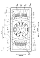
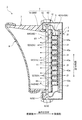
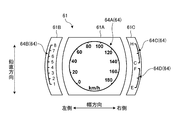
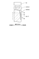
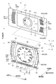
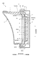
図1は、実施形態に係る表示装置の奥行き方向前面側の正面図である。図2は、図1に示すA−A断面図である。図3は、図1に示すB−B断面図である。図4は、実施形態に係る表示装置の文字板を表す正面図である。図5は、実施形態に係る表示装置の透明文字板を表す正面図である。図6は、図2に示す囲み線C内の部分的な断面図である。図7は、実施形態に係る表示装置の第1表示面、及び、第2表示面を含む要部の分解斜視図である。図8、図9、図10は、表示装置の輝度実測試験の前提条件について説明する模式図である。図11は、表示装置の輝度実測試験の結果を表す線図である。図12は、実施形態に係る表示装置の第2表示面の一部が非表示状態である場合の表示態様の一例を表す正面図である。図13は、変形例1に係る表示装置の断面図である。
[Embodiment]
FIG. 1 is a front view of the front side in the depth direction of the display device according to the embodiment. FIG. 2 is a cross-sectional view taken along line AA shown in FIG. 3 is a cross-sectional view taken along line BB shown in FIG. FIG. 4 is a front view illustrating the dial of the display device according to the embodiment. FIG. 5 is a front view illustrating the transparent dial of the display device according to the embodiment. FIG. 6 is a partial cross-sectional view taken along the encircling line C shown in FIG. FIG. 7 is an exploded perspective view of a main part including the first display surface and the second display surface of the display device according to the embodiment. 8, 9, and 10 are schematic diagrams for explaining the preconditions for the luminance measurement test of the display device. FIG. 11 is a diagram showing the result of the brightness measurement test of the display device. FIG. 12 is a front view illustrating an example of a display mode when a part of the second display surface of the display device according to the embodiment is in a non-display state. FIG. 13 is a cross-sectional view of a display device according to the first modification.

図1、図2、図3に示す本実施形態に係る表示装置1は、いわゆるメータを構成するものであり、例えば、自動車等の車両のダッシュボードに設けられたインストルメントパネルに搭載され、車両の運転に供される種々の情報を表示する。   The display device 1 according to the present embodiment shown in FIGS. 1, 2, and 3 constitutes a so-called meter, and is mounted on an instrument panel provided on a dashboard of a vehicle such as an automobile, for example. Various information used for driving is displayed.

なお、図1等に示す表示装置1の幅方向とは、典型的には、この表示装置1が適用される車両の車幅方向に相当する。以下の説明では、表示装置1の幅方向において、表示装置1の前面に向かって左側を幅方向左側、向かって右側を幅方向右側という。また、図2、図3等に示す表示装置1の奥行き方向とは、典型的には、この表示装置1が適用される車両の前後方向(言い換えれば、車両進行方向)に相当する。また、表示装置1の前面側とは、車両の運転席と対面する側であり、典型的には、当該運転席に座った運転者によって視認される側である。一方、表示装置1の背面側とは、奥行き方向において前面側とは反対側であり、典型的には、インストルメントパネルの内部に収容される側である。また、以下の説明で用いる各方向は、特に断りのない限り、表示装置1がインストルメントパネルに組み付けられた状態での方向を表す。   The width direction of the display device 1 shown in FIG. 1 and the like typically corresponds to the vehicle width direction of a vehicle to which the display device 1 is applied. In the following description, in the width direction of the display device 1, the left side toward the front surface of the display device 1 is referred to as the left side in the width direction, and the right side toward the front is referred to as the right side in the width direction. In addition, the depth direction of the display device 1 illustrated in FIGS. 2 and 3 typically corresponds to the front-rear direction of the vehicle to which the display device 1 is applied (in other words, the vehicle traveling direction). Further, the front side of the display device 1 is the side facing the driver's seat of the vehicle, and is typically the side visually recognized by the driver sitting in the driver's seat. On the other hand, the back side of the display device 1 is the side opposite to the front side in the depth direction, and is typically the side accommodated inside the instrument panel. Each direction used in the following description represents a direction in a state where the display device 1 is assembled to the instrument panel unless otherwise specified.

具体的には、表示装置1は、ケース2と、回路基板3と、背面側表示装置4と、文字板5と、前面側表示装置6と、見返し板7と、表ガラス8とを備える。表示装置1は、奥行き方向の背面側から前面側に向かって、ケース2、回路基板3、背面側表示装置4、文字板5、前面側表示装置6、見返し板7、表ガラス8の順で積層された構造となっている。本実施形態の表示装置1は、背面側表示装置4と前面側表示装置6とが奥行き方向に重なって設けられることで、ツーレイヤー式表示装置を構成する。   Specifically, the display device 1 includes a case 2, a circuit board 3, a back side display device 4, a dial plate 5, a front side display device 6, a turning plate 7, and a front glass 8. The display device 1 has a case 2, a circuit board 3, a back side display device 4, a dial plate 5, a front side display device 6, a facing plate 7, and a front glass 8 in this order from the back side to the front side in the depth direction. It has a laminated structure. The display device 1 of the present embodiment forms a two-layer display device by providing the back side display device 4 and the front side display device 6 overlapping in the depth direction.

ケース2は、樹脂材料等によって構成され、表示装置1を構成する種々の部品が組み付けられこれらを収容する筐体の一部を構成するものである。   The case 2 is made of a resin material or the like, and constitutes a part of a housing that accommodates various components that constitute the display device 1 and that accommodates them.

回路基板3は、表示装置1における各種機能を実現するための種々の電子部品、配線が実装されるものである。回路基板3は、ビス等の固定部材を介してケース2に組み付けられる。   The circuit board 3 is mounted with various electronic components and wirings for realizing various functions in the display device 1. The circuit board 3 is assembled to the case 2 via a fixing member such as a screw.

背面側表示装置4は、ツーレイヤー式の表示装置1において、奥行き方向背面側に位置する表示部であり、車両情報を表示する第1層目の表示面(後述する第1表示面11)を構成する。本実施形態の背面側表示装置4は、画像表示装置としてのディスプレイ41と、セグメント表示部42とを含んで構成される。背面側表示装置4が表示する車両情報としては、例えば、車両の速度やエコ走行等に関する情報の他、積算走行距離、冷却水温、走行用動力源の出力回転数、燃料残量、バッテリ蓄電量、ナビゲーション情報、地図情報、交差点情報等、車両の運転に際して時々刻々と変化する様々な運転に関する運転情報が含まれてもよい。   The back side display device 4 is a display unit located on the back side in the depth direction in the two-layer display device 1, and a first layer display surface (a first display surface 11 described later) for displaying vehicle information. Configure. The back side display device 4 of the present embodiment includes a display 41 as an image display device and a segment display unit 42. Examples of vehicle information displayed by the rear side display device 4 include information on vehicle speed, eco-travel, etc., as well as the total travel distance, cooling water temperature, output rotational speed of the driving power source, remaining fuel amount, and battery charge amount. Further, driving information relating to various driving that changes every moment during driving of the vehicle, such as navigation information, map information, and intersection information, may be included.

ディスプレイ41は、回路基板3等を介して駆動制御され、画像表示面41aに種々の車両情報に関する画像を表示するものである。画像表示面41aは、ディスプレイ41において略矩形状の表示領域を構成する。ディスプレイ41は、例えば、薄型の液晶ディスプレイを用いることができるが、これに限らず、プラズマディスプレイ、有機ELディスプレイ等を用いることもできる。ここでは、ディスプレイ41は、車両の速度を表示する速度計の一部を構成するものとして説明するがこれに限らない。ディスプレイ41は、速度計として機能する際には、例えば、画像表示面41aに車両情報として指針の実像画像(以下、単に「指針画像」という場合がある。)41b、及び、速度計の目盛を構成する実像画像(以下、単に「速度計小目盛画像」という場合がある。)41cを表示する。指針画像41bは、現在の計測値(ここでは速度)を指し示すための針状の画像であり、所定の回転中心を中心として回動する回動型の指針の画像である。速度計小目盛画像41cは、指針画像41bの周りに設けられ当該指針画像41bによって指し示される指標部の画像であり、指針画像41bの回転中心を中心とした円環と当該円環の内側に円周方向に沿って等間隔で設けられる目盛の画像である。速度計小目盛画像41cの目盛は、指針画像41bの先端の回動軌跡に沿って表示される。   The display 41 is driven and controlled via the circuit board 3 and the like, and displays images relating to various vehicle information on the image display surface 41a. The image display surface 41a forms a substantially rectangular display area on the display 41. As the display 41, for example, a thin liquid crystal display can be used, but not limited thereto, a plasma display, an organic EL display, or the like can also be used. Here, the display 41 is described as constituting a part of a speedometer that displays the speed of the vehicle, but is not limited thereto. When the display 41 functions as a speedometer, for example, a real image image of a pointer (hereinafter sometimes simply referred to as “pointer image”) 41b as vehicle information on the image display surface 41a and a scale of the speedometer. A real image image (hereinafter, simply referred to as “speedometer small scale image”) 41c to be configured is displayed. The pointer image 41b is a needle-like image for indicating the current measurement value (here, speed), and is a rotating pointer image that rotates around a predetermined rotation center. The speedometer small scale image 41c is an image of an index portion provided around the pointer image 41b and pointed to by the pointer image 41b, and an inner ring around the rotation center of the pointer image 41b. It is an image of the scale provided at equal intervals along the circumferential direction. The scale of the speedometer small scale image 41c is displayed along the turning trajectory of the tip of the pointer image 41b.

セグメント表示部42は、回路基板3等を介して駆動制御され、複数の光源42aが点灯、消灯することで種々の車両情報を表示するものである。セグメント表示部42は、鉛直方向に沿って等間隔で並んで設けられた複数の光源42aと、後述の文字板5に描かれたセグメントバー52とを含んで構成され、各光源42aの点灯、消灯に応じて各セグメントバー52の表示、非表示が切り替えられる表示灯式表示部である。各光源42aは、例えば、LED(Light Emitting Diode)素子等によって構成されるがこれに限らない。各光源42aは、それぞれケース2に形成された複数のランプハウジング21に1つずつ収容され、回路基板3に実装されて駆動制御される。各光源42aは、奥行き方向背面側から前面側に向けて光を照射する。ここでは、セグメント表示部42は、車両のエンジン回転数を表示する回転計の一部を構成する回転計セグメント表示部42A、車両の冷却水温を表示する水温計の一部を構成する水温計セグメント表示部42B、車両の燃料残量を表示する燃料計の一部を構成する燃料計セグメント表示部42Cの3つを含んで構成される。回転計セグメント表示部42Aは、ディスプレイ41の幅方向左側にケース2の鉛直方向上端部から下端部にかけて設けられる。水温計セグメント表示部42Bは、ディスプレイ41の幅方向右側にケース2の鉛直方向上端部から中央部にかけて設けられる。燃料計セグメント表示部42Cは、ディスプレイ41の幅方向右側でかつ水温計セグメント表示部42Bの鉛直方向下側にケース2の鉛直方向中央部から下端部にかけて設けられる。なお、以下の説明では、回転計セグメント表示部42A、水温計セグメント表示部42B、燃料計セグメント表示部42Cを特に区別して説明する必要がない場合には、単にセグメント表示部42という。   The segment display unit 42 is driven and controlled via the circuit board 3 and the like, and displays various vehicle information by turning on and off the plurality of light sources 42a. The segment display unit 42 includes a plurality of light sources 42a provided at equal intervals along the vertical direction, and a segment bar 52 drawn on the dial 5 described later. It is an indicator lamp type display unit in which the display and non-display of each segment bar 52 are switched according to turning off. Each light source 42a is configured by, for example, an LED (Light Emitting Diode) element or the like, but is not limited thereto. Each light source 42a is housed one by one in a plurality of lamp housings 21 formed in the case 2, mounted on the circuit board 3, and driven and controlled. Each light source 42a irradiates light from the depth direction back side toward the front side. Here, the segment display unit 42 includes a tachometer segment display unit 42A that forms part of a tachometer that displays the engine speed of the vehicle, and a thermometer segment that forms part of a water temperature meter that displays the coolant temperature of the vehicle. The display unit 42 </ b> B includes three fuel meter segment display units 42 </ b> C that constitute a part of the fuel meter that displays the fuel remaining amount of the vehicle. The tachometer segment display unit 42 </ b> A is provided on the left side in the width direction of the display 41 from the upper end to the lower end in the vertical direction of the case 2. The water temperature gauge segment display part 42B is provided on the right side in the width direction of the display 41 from the upper end in the vertical direction of the case 2 to the center. The fuel gauge segment display portion 42C is provided from the center in the vertical direction to the lower end of the case 2 on the right side in the width direction of the display 41 and on the lower side in the vertical direction of the water temperature gauge segment display portion 42B. In the following description, the tachometer segment display unit 42A, the water temperature meter segment display unit 42B, and the fuel meter segment display unit 42C are simply referred to as the segment display unit 42 when it is not necessary to distinguish between them.

文字板5は、図4に示すように、表示する車両情報に応じた種々の図柄、記号、文字列等が描かれた板状の部材である。文字板5は、例えば、透明生地のポリカーボネイト製シートであり、暗色系のインクによって、上記図柄、記号、文字列等に対応した形状が中抜きされた印刷が施されることで、上記図柄、記号、文字列等が描かれている。ここでは、文字板5は、ほぼ中央部に略矩形状の開口部51が形成されている。上述のディスプレイ41は、前面側の表面が当該開口部51を介して文字板5の前面側に露出しており、このディスプレイ41の前面側の表面が上述の略矩形状の画像表示面41aの表示領域を構成する。また、文字板5は、車両情報に関する図柄、記号、文字列として、少なくとも複数のセグメントバー52等を含んで構成される。文字板5は、これらセグメントバー52の部分が上述の中抜きされた部分であり、すなわち、光を透過する部分である。各セグメントバー52は、幅方向に沿って矩形棒状に形成される。各セグメントバー52は、上述したセグメント表示部42の一部を構成する。複数のセグメントバー52は、回転計セグメント表示部42Aの各光源42aに対応して1つずつ形成される回転計セグメントバー52A、水温計セグメント表示部42Bの各光源42aに対応して1つずつ形成される水温計セグメントバー52B、燃料計セグメント表示部42Cの各光源42aに対応して1つずつ形成される燃料計セグメントバー52Cを含んで構成される。回転計セグメントバー52Aは、開口部51の幅方向左側に鉛直方向に沿って等間隔で並んで設けられ、水温計セグメントバー52B、燃料計セグメントバー52Cは、開口部51の幅方向右側にそれぞれ鉛直方向に沿って等間隔で並んで設けられる。ここでは、回転計セグメントバー52A、水温計セグメントバー52B、燃料計セグメントバー52Cは、それぞれ若干湾曲させて配列されている。なお、以下の説明では、回転計セグメントバー52A、水温計セグメントバー52B、燃料計セグメントバー52Cを特に区別して説明する必要がない場合には、単にセグメントバー52という。   As shown in FIG. 4, the dial plate 5 is a plate-like member on which various symbols, symbols, character strings, and the like corresponding to the vehicle information to be displayed are drawn. The dial plate 5 is, for example, a polycarbonate sheet made of a transparent fabric, and is printed with a dark color ink in which the shape corresponding to the design, symbol, character string, etc. is hollowed out. Symbols, character strings, etc. are drawn. Here, the dial plate 5 has a substantially rectangular opening 51 formed substantially at the center. The front surface of the display 41 is exposed to the front surface of the dial 5 through the opening 51, and the front surface of the display 41 is the above-described substantially rectangular image display surface 41a. Configure the display area. The dial plate 5 includes at least a plurality of segment bars 52 and the like as symbols, symbols, and character strings related to vehicle information. The dial plate 5 is a portion in which the segment bars 52 are cut out, that is, a portion that transmits light. Each segment bar 52 is formed in a rectangular bar shape along the width direction. Each segment bar 52 constitutes a part of the segment display unit 42 described above. The plurality of segment bars 52 are formed one by one corresponding to each light source 42a of the tachometer segment display unit 42A, and one by one corresponding to each light source 42a of the water temperature meter segment display unit 42B. A water temperature gauge segment bar 52B to be formed and a fuel gauge segment bar 52C to be formed one by one corresponding to each light source 42a of the fuel gauge segment display section 42C are configured. The tachometer segment bar 52A is provided at equal intervals along the vertical direction on the left side in the width direction of the opening 51, and the water temperature gauge segment bar 52B and the fuel gauge segment bar 52C are on the right side in the width direction of the opening 51, respectively. They are provided side by side at equal intervals along the vertical direction. Here, the tachometer segment bar 52A, the water temperature gauge segment bar 52B, and the fuel gauge segment bar 52C are arranged in a slightly curved manner. In the following description, the tachometer segment bar 52A, the water temperature gauge segment bar 52B, and the fuel gauge segment bar 52C are simply referred to as the segment bar 52 when it is not necessary to distinguish between them.

セグメント表示部42は、セグメント表示部42の各光源42aがそれぞれ個別に点灯することで、文字板5の奥行き方向背面側から光が照射され、各セグメントバー52の部分において当該照射された光が透過されることで、各セグメントバー52がそれぞれ個別に点灯される。一方、セグメント表示部42は、各光源42aがそれぞれ個別に消灯されることで、各セグメントバー52が個別に消灯される。   The segment display unit 42 is irradiated with light from the back side in the depth direction of the dial plate 5 by individually illuminating each light source 42a of the segment display unit 42, and the irradiated light at each segment bar 52 portion. Each segment bar 52 is individually lit by being transmitted. On the other hand, in the segment display section 42, each segment bar 52 is individually turned off by individually turning off each light source 42a.

図1、図2、図3に戻って、前面側表示装置6は、ツーレイヤー式の表示装置1において、奥行き方向前面側に位置する表示部であり、所定の図柄を表示する第2層目の表示面(後述する第2表示面12)を構成する。前面側表示装置6は、透明文字板61と、光源62と、回路基板63とを含んで構成される。   1, 2, and 3, the front side display device 6 is a display unit located on the front side in the depth direction in the two-layer display device 1, and is a second layer that displays a predetermined design. Display surface (second display surface 12 to be described later). The front display device 6 includes a transparent dial 61, a light source 62, and a circuit board 63.

透明文字板61は、背面側表示装置4の前面側、さらに言えば、文字板5の前面側に重ねて設けられる。透明文字板61は、ディスプレイ41から照射された光を透過する透過性を有する透明部材(透明媒体)によって形成される透明導光板である。透明文字板61は、図1、図5に示すように、メイン透明文字板61Aと、当該メイン透明文字板61Aの幅方向両側に設けられる一対のサブ透明文字板61B、61Cの3つを含んで構成される。メイン透明文字板61Aは、少なくとも一部が背面側表示装置4のうちのディスプレイ41の前面側に重なるようにして設けられる。ここでは、メイン透明文字板61Aは、鉛直方向の両端面が幅方向に沿った直線状でかつ幅方向の両端面が外側に突出した曲線状に形成された樽型形状に形成される。サブ透明文字板61Bは、少なくとも一部が背面側表示装置4のうち回転計セグメント表示部42Aの前面側に重なるようにして設けられる。ここでは、サブ透明文字板61Bは、鉛直方向の両端面が幅方向に沿った直線状でかつ幅方向の両端面がメイン透明文字板61Aの幅方向左側の端面の曲線に沿って湾曲した形状に形成される。サブ透明文字板61Cは、少なくとも一部が背面側表示装置4のうち水温計セグメント表示部42B、及び、燃料計セグメント表示部42Cの前面側に重なるようにして設けられる。ここでは、サブ透明文字板61Cは、鉛直方向の両端面が幅方向に沿った直線状でかつ幅方向の両端面がメイン透明文字板61Aの幅方向右側の端面の曲線に沿って湾曲した形状に形成される。なお、以下の説明では、メイン透明文字板61A、サブ透明文字板61B、61Cを特に区別して説明する必要がない場合には、単に透明文字板61という。   The transparent dial 61 is provided so as to overlap the front side of the back side display device 4, that is, the front side of the dial 5. The transparent dial 61 is a transparent light guide plate formed by a transparent member (transparent medium) having transparency that transmits light emitted from the display 41. As shown in FIGS. 1 and 5, the transparent dial 61 includes a main transparent dial 61A and a pair of sub transparent dials 61B and 61C provided on both sides in the width direction of the main transparent dial 61A. Consists of. The main transparent dial 61 </ b> A is provided so that at least a part thereof overlaps the front side of the display 41 of the back side display device 4. Here, the main transparent dial 61A is formed in a barrel shape in which both end faces in the vertical direction are linear along the width direction and curved in such a manner that both end faces in the width direction protrude outward. The sub transparent dial 61 </ b> B is provided so that at least a part thereof overlaps the front side of the tachometer segment display unit 42 </ b> A in the back side display device 4. Here, the sub transparent dial 61B has a shape in which both end faces in the vertical direction are linear along the width direction, and both end faces in the width direction are curved along a curve on the left end face in the width direction of the main transparent dial 61A. Formed. The sub transparent dial 61C is provided so that at least a part thereof overlaps the front side of the water temperature gauge segment display part 42B and the fuel gauge segment display part 42C in the back side display device 4. Here, the sub transparent dial 61C has a shape in which both end faces in the vertical direction are linear along the width direction, and both end faces in the width direction are curved along a curve on the right end face in the width direction of the main transparent dial 61A. Formed. In the following description, the main transparent dial plate 61A and the sub transparent dial plates 61B and 61C are simply referred to as the transparent dial plate 61 when it is not necessary to distinguish between them.

透明文字板61は、図1、図2、図3、図5、図6等に示すように、図柄(表示意匠)64を構成する凹凸部としての複数の微細な溝65が形成される。図柄64を構成する溝65は、例えば、レーザー加工等の種々の手法による掘り込みによって、透明文字板61の主面上、ここでは、当該透明文字板61の背面側の主面上に凹形状となるように形成されてもよい。また、図柄64を構成する溝65は、例えば、当該溝65に相当する凸形状を設けた金型を用いて透明文字板61を樹脂成形することによって、透明文字板61の主面上、ここでは、当該透明文字板61の背面側の主面上に凹形状となるように形成されてもよい。ここでは、複数の微細な溝65は、幅方向に沿って形成される。すなわち、溝65の延在方向L1は、幅方向に沿った方向である。なお、この溝65の延在方向L1については、後で詳細に説明する。透明文字板61に溝65によって形成される図柄64としては、例えば、ディスプレイ41で表示される運転情報と関連するような種々の図柄が含まれてもよい。   As shown in FIGS. 1, 2, 3, 5, 6, and the like, the transparent dial 61 is formed with a plurality of fine grooves 65 as concavo-convex portions constituting a design (display design) 64. The groove 65 constituting the pattern 64 is formed in a concave shape on the main surface of the transparent dial 61, here, on the main surface on the back side of the transparent dial 61, by digging by various methods such as laser processing, for example. May be formed. Further, the groove 65 constituting the pattern 64 is formed on the main surface of the transparent dial 61 by, for example, resin-molding the transparent dial 61 using a mold having a convex shape corresponding to the groove 65. Then, it may be formed in a concave shape on the main surface on the back side of the transparent dial 61. Here, the plurality of fine grooves 65 are formed along the width direction. That is, the extending direction L1 of the groove 65 is a direction along the width direction. The extending direction L1 of the groove 65 will be described later in detail. The symbols 64 formed by the grooves 65 on the transparent dial 61 may include various symbols related to the driving information displayed on the display 41, for example.

ここでは、透明文字板61のうちメイン透明文字板61Aは、図柄64として、微細な溝65によって、速度計の目盛を構成する実像図柄(以下、単に「速度計大目盛図柄」という場合がある。)64Aが描かれている。速度計大目盛図柄64Aは、ディスプレイ41が速度計として機能する際に指針画像41bの周りに設けられ当該指針画像41bによって指し示される指標部となる図柄である。速度計大目盛図柄64Aは、指針画像41bの回転中心を中心とした円環と当該円環の内側に円周方向に沿って等間隔で設けられる目盛、速度を表す数字、及び、単位[km/h]の図柄を含んで構成される。速度計大目盛図柄64Aの目盛は、指針画像41bの先端の回動軌跡に沿って描かれる。速度計大目盛図柄64Aは、速度計小目盛画像41cの円環よりも大きな円環であると共に目盛の間隔が速度計小目盛画像41cの間隔よりも相対的に広くなっている。   Here, the main transparent dial 61 </ b> A among the transparent dials 61 may be referred to as a real image symbol (hereinafter simply referred to as a “speedometer large scale symbol”) that constitutes a scale of the speedometer by the minute groove 65 as the symbol 64. .) 64A is drawn. The speedometer large scale symbol 64A is a symbol which is provided around the pointer image 41b when the display 41 functions as a speedometer and serves as an index portion indicated by the pointer image 41b. The speedometer large scale symbol 64A includes an annulus centered on the rotation center of the pointer image 41b, a scale provided at equal intervals along the circumferential direction inside the annulus, a number representing a speed, and a unit [km / H]. The scale of the speedometer large scale pattern 64A is drawn along the turning locus of the tip of the pointer image 41b. The speedometer large scale symbol 64A is a ring larger than the ring of the speedometer small scale image 41c, and the interval of the scales is relatively wider than the interval of the speedometer small scale image 41c.

透明文字板61のうちサブ透明文字板61Bは、図柄64として、微細な溝65によって、回転計の目盛を構成する実像図柄(以下、単に「回転計目盛図柄」という場合がある。)64Bが描かれている。回転計目盛図柄64Bは、回転計セグメント表示部42Aに重畳するようにして描かれ回転計セグメントバー52Aによって指し示される指標部となる図柄である。回転計目盛図柄64Bは、鉛直方向に沿って延びる円弧状の基準線と当該基準線の幅方向右側に設けられた目盛、及び、回転数を表す数字の図柄を含んで構成される。   Among the transparent dials 61, the sub transparent dial 61B has a real image symbol (hereinafter, sometimes simply referred to as “rotometer scale symbol”) 64B constituting a scale of the tachometer by the minute groove 65 as the pattern 64. It is drawn. The tachometer scale symbol 64B is a symbol that becomes an indicator portion drawn so as to be superimposed on the tachometer segment display portion 42A and pointed to by the tachometer segment bar 52A. The tachometer scale symbol 64B is configured to include an arc-shaped reference line extending along the vertical direction, a scale provided on the right side in the width direction of the reference line, and a numerical symbol representing the rotation speed.

透明文字板61のうちサブ透明文字板61Cは、図柄64として、微細な溝65によって、水温計の目盛を構成する実像図柄(以下、単に「水温計目盛図柄」という場合がある。)64C、及び、燃料計の目盛を構成する実像図柄(以下、単に「燃料計目盛図柄」という場合がある。)64Dが描かれている。水温計目盛図柄64Cは、水温計セグメント表示部42Bに重畳するようにして描かれ水温計セグメントバー52Bによって指し示される指標部となる図柄である。水温計目盛図柄64Cは、鉛直方向に沿って延びる円弧状の基準線と当該基準線の幅方向左側に設けられた目盛、及び、水温の高低を表す文字「H」、「C」の図柄を含んで構成される。燃料計目盛図柄64Dは、燃料計セグメント表示部42Cに重畳するようにして描かれ燃料計セグメントバー52Cによって指し示される指標部となる図柄である。燃料計目盛図柄64Dは、鉛直方向に沿って延びる円弧状の基準線と当該基準線の幅方向左側に設けられた目盛、及び、燃料残量を表す文字「F」、「E」の図柄を含んで構成される。   Of the transparent dial 61, the sub transparent dial 61C has a real image symbol (hereinafter, sometimes simply referred to as a “water temperature meter scale symbol”) 64C constituting a scale of the water thermometer by the fine groove 65 as the symbol 64. In addition, a real image symbol constituting the scale of the fuel gauge (hereinafter sometimes simply referred to as “fuel gauge scale symbol”) 64D is depicted. The water thermometer scale symbol 64C is a symbol that is drawn so as to be superimposed on the water thermometer segment display portion 42B and serves as an index portion indicated by the water thermometer segment bar 52B. The water temperature meter scale symbol 64C includes an arc-shaped reference line extending along the vertical direction, a scale provided on the left side in the width direction of the reference line, and symbols "H" and "C" indicating the level of the water temperature. Consists of including. The fuel gauge scale symbol 64D is a symbol that is drawn so as to be superimposed on the fuel gauge segment display part 42C and serves as an index part indicated by the fuel gauge segment bar 52C. The fuel gauge scale symbol 64D includes an arc-shaped reference line extending along the vertical direction, a scale provided on the left side in the width direction of the reference line, and symbols "F" and "E" indicating the remaining fuel amount. Consists of including.

なお、以下の説明では、速度計大目盛図柄64A、回転計目盛図柄64B、水温計目盛図柄64C、燃料計目盛図柄64Dを特に区別して説明する必要がない場合には、単に図柄64という。   In the following description, the speedometer large scale symbol 64A, the tachometer scale symbol 64B, the water temperature meter scale symbol 64C, and the fuel meter scale symbol 64D are simply referred to as the symbol 64 when there is no need to distinguish them.

光源62は、透明文字板61の端面に光を照射する。光源62は、例えば、LED(Light Emitting Diode)素子等によって構成されるが、これに限らない。光源62は、その光軸方向が透明文字板61の端面と直交し、かつ、照射された光が透明文字板61の端面から入射するように設けられている。光源62は、透明文字板61の鉛直方向の上端面、及び、下端面と対向する位置に、それぞれ幅方向に沿って所定の間隔をあけて複数設けられる。ここでは、各光源62は、その光軸方向が鉛直方向に沿うように配置され、これにより、光源62による光の照射方向L2が鉛直方向に沿った方向となる。つまり、透明文字板61の鉛直方向の上端面と対向する各光源62は、鉛直方向に沿って下向きに光を照射し、透明文字板61の鉛直方向の下端面と対向する各光源62は、鉛直方向に沿って上向きに光を照射する。ここでは、上述の溝65の延在方向L1と光の照射方向(言い換えれば光軸方向)L2とは、互いに直交する。各光源62は、例えば、前面側から視て後述の見返し板7等によって隠れる位置に配置される。   The light source 62 irradiates the end face of the transparent dial 61 with light. The light source 62 includes, for example, an LED (Light Emitting Diode) element, but is not limited thereto. The light source 62 is provided such that the optical axis direction is orthogonal to the end face of the transparent dial 61 and the irradiated light is incident from the end face of the transparent dial 61. A plurality of light sources 62 are provided at predetermined positions along the width direction at positions facing the upper end surface and the lower end surface of the transparent dial 61 in the vertical direction. Here, each light source 62 is arranged so that the optical axis direction thereof is along the vertical direction, whereby the light irradiation direction L <b> 2 by the light source 62 is a direction along the vertical direction. That is, each light source 62 facing the upper end surface of the transparent dial 61 in the vertical direction emits light downward along the vertical direction, and each light source 62 facing the lower end surface of the transparent dial 61 in the vertical direction is Light is irradiated upward along the vertical direction. Here, the extending direction L1 of the groove 65 and the light irradiation direction (in other words, the optical axis direction) L2 are orthogonal to each other. For example, each light source 62 is disposed at a position hidden by a turn-off plate 7 described later when viewed from the front side.

回路基板63は、各光源62、及び、メインの回路基板3に電気的に接続される。各光源62は、回路基板3、及び、回路基板63等を介して駆動制御される。各光源62は、典型的には、メイン透明文字板61Aの端面に沿って設けられた光源62と、サブ透明文字板61Bの端面に沿って設けられた光源62と、サブ透明文字板61Cの端面に沿って設けられた光源62とをそれぞれ個別に点灯、消灯を切り替えることができる。   The circuit board 63 is electrically connected to each light source 62 and the main circuit board 3. Each light source 62 is driven and controlled via the circuit board 3, the circuit board 63, and the like. Each light source 62 typically includes a light source 62 provided along the end face of the main transparent dial 61A, a light source 62 provided along the end face of the sub transparent dial 61B, and a sub transparent dial 61C. The light source 62 provided along the end face can be individually switched on and off.

上記のように構成される前面側表示装置6は、各光源62が回路基板3、回路基板63等を介して駆動制御されることで、光源62の点灯、消灯に基づいて、図柄64の表示、非表示が切り替えられる。前面側表示装置6は、光源62が点灯すると図柄64が発光表示された状態となり、すなわち、光源62から照射された光が透明文字板61の端面に入射して当該透明文字板61内を伝播し、少なくとも当該入射光の一部の成分が図柄64を構成する溝65で前面側に反射し、この結果、運転者等が当該図柄64を視認可能な状態となる(図6等参照)。この場合、前面側表示装置6は、運転者が前面側(運転席側)から視たときに、透明文字板61上に表示される図柄64を、ディスプレイ41の画像表示面41a上の画像(指針画像41b、速度計小目盛画像41c)やセグメント表示部42の各セグメントバー52上に重畳させて表示して所定の意匠を形成し、これにより、多様な表示を可能とすることができる。一方、前面側表示装置6は、光源62が消灯すると図柄64が非表示の状態となり、ディスプレイ41等から照射され透明文字板61を透過した光によって、運転者等が画像表示面41a等に表示された種々の画像を視認しやすい状態となる。   In the front side display device 6 configured as described above, each light source 62 is driven and controlled via the circuit board 3, the circuit board 63, and the like, so that the display of the symbol 64 is displayed based on the turning on and off of the light source 62. , Non-display is switched. When the light source 62 is turned on, the front side display device 6 is in a state where the pattern 64 is lit and displayed. That is, the light emitted from the light source 62 is incident on the end face of the transparent dial 61 and propagates through the transparent dial 61. Then, at least a part of the incident light component is reflected to the front side by the groove 65 constituting the symbol 64, and as a result, the driver or the like can visually recognize the symbol 64 (see FIG. 6 and the like). In this case, the front side display device 6 displays the symbol 64 displayed on the transparent dial 61 when the driver views from the front side (driver's seat side) on the image (on the image display surface 41a of the display 41 ( The pointer image 41b, the speedometer small scale image 41c) and the segment bar 52 of the segment display unit 42 are superimposed and displayed to form a predetermined design, thereby enabling various displays. On the other hand, in the front side display device 6, when the light source 62 is turned off, the pattern 64 is not displayed, and the driver or the like is displayed on the image display surface 41a or the like by the light irradiated from the display 41 or the like and transmitted through the transparent dial 61. It will be in the state which is easy to visually recognize the various images which were carried out.

見返し板7は、文字板5、透明文字板61等の周囲を囲って当該文字板5、透明文字板61等を押える枠状の部材である。見返し板7は、ケース2に組み付けられる。   The facing plate 7 is a frame-like member that surrounds the dial plate 5, the transparent dial plate 61, and the like and presses the dial plate 5, the transparent dial plate 61, and the like. The facing plate 7 is assembled to the case 2.

表ガラス8は、光を透過する光透過性を有する保護部材であり、見返し板7に組み付けられる。   The front glass 8 is a protective member having light permeability that transmits light, and is assembled to the facing plate 7.

ここで、図1、図2、図3、図7に示すように、上記のように背面側表示装置4によって構成される第1層目の表示面は、車両情報を表示する第1表示面11を構成する。一方、上記のように前面側表示装置6によって構成される第2層目の表示面は、第1表示面11に重ねて設けられ光を透過すると共に、図柄64を有し当該図柄64を表示する表示状態と、当該図柄64を非表示とする非表示状態とに切り替え可能である第2表示面12を構成する。第1表示面11と第2表示面12とは、奥行き方向、言い換えれば、車両進行方向に、重ねられた複数の表示面を構成し、第1表示面11が当該複数の表示面の車両進行方向奥側の表示面を構成し、第2表示面12が当該複数の表示面の車両進行方向手前側(運転者等の目視者の目視位置側)の表示面を構成する。ここでは、第1表示面11と第2表示面12とは、奥行き方向に沿って間隔をあけて対向して設けられることで、第1表示面11と第2表示面12とが間をあけて重ねて設けられる。   Here, as shown in FIGS. 1, 2, 3, and 7, the first-layer display surface configured by the rear display device 4 as described above is a first display surface that displays vehicle information. 11 is configured. On the other hand, the display surface of the second layer configured by the front display device 6 as described above is provided so as to overlap the first display surface 11 and transmits light, and has a design 64 and displays the design 64. The second display surface 12 can be switched between a display state to be displayed and a non-display state in which the symbol 64 is not displayed. The first display surface 11 and the second display surface 12 constitute a plurality of display surfaces stacked in the depth direction, in other words, the vehicle traveling direction, and the first display surface 11 travels on the plurality of display surfaces. The second display surface 12 constitutes a display surface on the front side in the vehicle traveling direction of the plurality of display surfaces (viewing position side of a viewer such as a driver). Here, the first display surface 11 and the second display surface 12 are provided to face each other at an interval along the depth direction, so that the first display surface 11 and the second display surface 12 are spaced from each other. Are provided in layers.

より具体的には、第1表示面11は、文字板5の開口部51から露出したディスプレイ41の画像表示面41aと文字板5において各セグメントバー52とが形成された面によって構成される。すなわち、第1表示面11は、略矩形状に形成された画像表示面41aの表示領域を含むと共に、各セグメントバー52による矩形棒状の表示領域とを含む。   More specifically, the first display surface 11 includes an image display surface 41 a of the display 41 exposed from the opening 51 of the dial plate 5 and a surface on which the segment bars 52 are formed on the dial plate 5. That is, the first display surface 11 includes a display area of the image display surface 41 a formed in a substantially rectangular shape, and also includes a rectangular bar-shaped display area formed by the segment bars 52.

一方、第2表示面12は、図柄64を構成する溝65が形成された透明文字板61の背面側の主面によって構成される。第2表示面12は、第1表示面11の状態にかかわらず各光源62の点灯、消灯に応じて表示状態と非表示状態とを切り替え可能である。ここで、第2表示面12の表示状態とは、光源62から照射される光によって図柄64を表示する状態である。一方、第2表示面12の非表示状態とは、光源62が消灯することで当該図柄64を非表示とする状態である。   On the other hand, the 2nd display surface 12 is comprised by the main surface by the side of the back surface of the transparent dial 61 in which the groove | channel 65 which comprises the pattern 64 was formed. Regardless of the state of the first display surface 11, the second display surface 12 can be switched between a display state and a non-display state depending on whether each light source 62 is turned on or off. Here, the display state of the second display surface 12 is a state in which the symbol 64 is displayed by the light emitted from the light source 62. On the other hand, the non-display state of the second display surface 12 is a state in which the symbol 64 is not displayed when the light source 62 is turned off.

そして、本実施形態の表示装置1は、少なくとも図柄64の一部が第1表示面11と第2表示面12との積層方向に沿って視て第1表示面11の表示領域内と表示領域外とにまたがって描かれることで、表示領域を相対的に大きく見せる視覚効果を得ることができるようにしている。ここで、第1表示面11と第2表示面12との積層方向とは、典型的には、奥行き方向であり、図柄64は、奥行き方向に沿って前面側から視て第1表示面11の表示領域内と表示領域外とにまたがって形成される。つまり、図柄64は、第1表示面11における表示領域と非表示領域との境界にまたがって重なるようにして描かれる。さらに言えば、第1表示面11の表示領域内と表示領域外とにまたがって描かれた図柄64とは、ここでは、少なくとも当該図柄64の一部が第1表示面11における表示領域と非表示領域との境界線上にて当該境界線と交差する連続した線を有するものである。   In the display device 1 of the present embodiment, at least a part of the design 64 is viewed along the stacking direction of the first display surface 11 and the second display surface 12, and the display area and the display area of the first display surface 11 are displayed. By drawing over the outside, a visual effect that makes the display area relatively large can be obtained. Here, the stacking direction of the first display surface 11 and the second display surface 12 is typically the depth direction, and the design 64 is viewed from the front side along the depth direction. It is formed across the display area and outside the display area. That is, the pattern 64 is drawn so as to overlap the boundary between the display area and the non-display area on the first display surface 11. Further, the symbol 64 drawn across the display area of the first display surface 11 and the outside of the display region is, here, at least a part of the symbol 64 is different from the display region on the first display surface 11. It has a continuous line intersecting with the boundary line on the boundary line with the display area.

図柄64のうち速度計大目盛図柄64Aは、第1表示面11を構成する画像表示面41aの前面側に描かれ、画像表示面41aの表示領域内と表示領域外とにまたがって描かれる。速度計大目盛図柄64Aは、第1表示面11の矩形状の表示領域、ここでは、略矩形状に形成された画像表示面41aの表示領域内から表示領域外に張り出した円弧状の部分64a(図1参照)を含む。ここでは、速度計大目盛図柄64Aは、正円形状に形成された円環の一部分が画像表示面41aの表示領域の鉛直方向上側、及び、下側にはみ出るように描かれることで表示領域内から表示領域外に張り出した円弧状の部分64aを構成し、これにより、当該表示領域内と表示領域外とにまたがって描かれる。図柄64のうち回転計目盛図柄64B、水温計目盛図柄64C、燃料計目盛図柄64Dは、それぞれ第1表示面11を構成する各セグメントバー52の前面側に描かれ、各セグメントバー52の表示領域内と表示領域外とにまたがって描かれる。回転計目盛図柄64B、水温計目盛図柄64C、燃料計目盛図柄64Dは、それぞれ各セグメント表示部42の各セグメントバー52による表示領域内から表示領域外にまたがって描かれる。   Of the symbols 64, the speedometer large scale symbol 64A is drawn on the front side of the image display surface 41a constituting the first display surface 11, and is drawn across the display area and the outside of the display area of the image display surface 41a. The speedometer large scale pattern 64A is a rectangular display area of the first display surface 11, here, an arc-shaped portion 64a protruding outside the display area from the display area of the image display surface 41a formed in a substantially rectangular shape. (See FIG. 1). Here, the speedometer large scale pattern 64A is drawn in such a manner that a part of a circular ring formed in a perfect circle shape protrudes vertically above and below the display area of the image display surface 41a. An arc-shaped portion 64a that projects from the display area to the outside of the display area is formed, and is drawn across the display area and the display area. Among the symbols 64, the tachometer scale symbol 64B, the water temperature meter scale symbol 64C, and the fuel meter scale symbol 64D are drawn on the front side of each segment bar 52 constituting the first display surface 11, and the display area of each segment bar 52 is displayed. It is drawn across the inside and outside the display area. The tachometer scale symbol 64B, the water temperature gauge scale symbol 64C, and the fuel gauge scale symbol 64D are drawn across the display area from the display area by the segment bars 52 of the segment display units 42, respectively.

上記のように表示装置1は、第2表示面12で表示される図柄64が第1表示面11の表示領域内と表示領域外とにまたがって形成されることで、第1表示面11で車両情報を表示できない領域にまで第2表示面12によって図柄64を表示することができる。これにより、表示装置1は、第1表示面11の表示領域外に第2表示面12による表示領域を拡張し、表示装置1全体での表示領域を相対的に大きく見せる視覚効果を創出している。   As described above, in the display device 1, the pattern 64 displayed on the second display surface 12 is formed across the display area of the first display surface 11 and the outside of the display area. The symbol 64 can be displayed on the second display surface 12 up to an area where vehicle information cannot be displayed. Thereby, the display device 1 creates a visual effect that expands the display region of the second display surface 12 outside the display region of the first display surface 11 and makes the display region of the entire display device 1 relatively large. Yes.

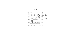
ここでさらに、本実施形態の表示装置1は、図7に示すように、背面側表示装置4が照射する光の偏光方向L3と各図柄64を構成する溝65の延在方向L1とが所定の角度範囲で交差するように構成することで、背面側表示装置4と前面側表示装置6とを組み合わせて多様な表示を実現した上で、適正な視認性を確保することができるようにしている。ここで、溝65の延在方向L1とは、典型的には、当該溝65が延びる方向に相当する。また、背面側表示装置4が照射する光の偏光方向L3とは、言い換えれば第1表示面11が照射する光の偏光方向に相当する。   Further, as shown in FIG. 7, the display device 1 of the present embodiment has a predetermined polarization direction L3 of the light irradiated by the back side display device 4 and an extending direction L1 of the groove 65 constituting each symbol 64. By configuring so as to intersect within the angle range, it is possible to ensure appropriate visibility after realizing various displays by combining the rear display device 4 and the front display device 6. Yes. Here, the extending direction L1 of the groove 65 typically corresponds to a direction in which the groove 65 extends. Further, the polarization direction L3 of the light irradiated by the back side display device 4 corresponds to the polarization direction of the light irradiated by the first display surface 11 in other words.

本実施形態の背面側表示装置4を構成するディスプレイ41は、一方向に偏光された光を照射し車両情報に関する画像(指針画像41b、速度計小目盛画像41c等)を表示する構成となっている。すなわち、ディスプレイ41は、バックライトから発せられた光が、偏光板等を介して偏光方向L3を透過軸方向として揃えられ、当該偏光方向L3(透過軸方向)に沿った振動方向の光を出射することで一方向に偏光された光を出射する。ここで、ディスプレイ41の偏光方向L3とは、典型的には、ディスプレイ41における最終的な透過軸方向に相当する。ディスプレイ41は、典型的には、最終的な偏光板の前面が上述の画像表示面41aの表面を構成し、当該偏光板の前面側に透明文字板61が配置され、偏光方向L3に沿った振動方向の光が透明文字板61に入射する。ここでは、偏光方向L3は、鉛直方向に沿った方向とされている。   The display 41 that constitutes the back side display device 4 of the present embodiment is configured to irradiate light polarized in one direction and display images related to vehicle information (eg, a pointer image 41b and a speedometer small scale image 41c). Yes. That is, in the display 41, light emitted from the backlight is aligned with the polarization direction L3 as the transmission axis direction via a polarizing plate or the like, and emits light in a vibration direction along the polarization direction L3 (transmission axis direction). As a result, light polarized in one direction is emitted. Here, the polarization direction L3 of the display 41 typically corresponds to the final transmission axis direction of the display 41. In the display 41, typically, the front surface of the final polarizing plate constitutes the surface of the above-described image display surface 41a, and the transparent dial 61 is disposed on the front side of the polarizing plate along the polarization direction L3. Light in the vibration direction is incident on the transparent dial 61. Here, the polarization direction L3 is a direction along the vertical direction.

なお、以上の説明では、ディスプレイ41の偏光方向L3について説明したが、セグメント表示部42の各光源42aと透明文字板61との間に、当該各光源42aからの光を、一方向、ここでは、偏光方向L3に偏光された光にする偏光板を設けることで、セグメント表示部42から照射される光も偏光方向L3に偏光された光とすることができる。これにより、背面側表示装置4は、ディスプレイ41とセグメント表示部42とを含む全体が照射する光の偏光方向を偏光方向L3とすることもできる。   In the above description, the polarization direction L3 of the display 41 has been described. However, light from each light source 42a is transmitted in one direction, here, between each light source 42a of the segment display unit 42 and the transparent dial 61. By providing a polarizing plate that makes light polarized in the polarization direction L3, the light emitted from the segment display unit 42 can also be light polarized in the polarization direction L3. Thereby, the back side display apparatus 4 can also make the polarization direction of the light which the whole including the display 41 and the segment display part 42 irradiate into the polarization direction L3.

一方、図柄(表示意匠)64を構成する複数の微細な溝65は、例えば、図6等に示すように、略V字状の断面形状で、ピッチが1μm以下(下限値は例えば製造上可能な寸法)で形成されることが好ましい。また、各溝65は、一方向に延在する直線溝として形成される。また、透明文字板61は、図柄64の領域の材質の透過率と透明文字板61における図柄64の周囲の領域の材質の透過率とが同等となるように構成される。このような微細な溝65によって構成される回折格子では、光の振動方向が溝65の延在方向L1に対して垂直(直交)である場合と、平行である場合とで回折効率が異なる傾向にある。すなわち、このような微細な溝65によって構成される回折格子は、典型的には、振動方向が溝65の延在方向L1に対して垂直である光を透過する一方、振動方向が溝65の延在方向L1に対して平行である光を遮断する傾向にある。つまり、透明文字板61上に形成された微細な溝65は、偏光板と類似する作用を示し、溝65の延在方向L1と直交する方向を透過軸方向とし、当該透過軸方向に振動する光を透過する一方、当該透過軸方向と直交する吸収軸方向(溝65の延在方向L1)に振動する光の大部分を遮断する。   On the other hand, the plurality of fine grooves 65 constituting the design (display design) 64 have, for example, a substantially V-shaped cross-sectional shape as shown in FIG. 6 and the like, and the pitch is 1 μm or less (the lower limit value can be manufactured, for example) Preferably). Each groove 65 is formed as a linear groove extending in one direction. The transparent dial 61 is configured such that the transmittance of the material in the area of the symbol 64 is equal to the transmittance of the material in the area around the symbol 64 in the transparent dial 61. In the diffraction grating constituted by such fine grooves 65, the diffraction efficiency tends to be different depending on whether the vibration direction of light is perpendicular (orthogonal) to the extending direction L1 of the groove 65 or parallel. It is in. That is, the diffraction grating constituted by such fine grooves 65 typically transmits light whose vibration direction is perpendicular to the extending direction L1 of the grooves 65, while the vibration direction is the grooves 65. There is a tendency to block light that is parallel to the extending direction L1. That is, the fine groove 65 formed on the transparent dial 61 exhibits an action similar to that of a polarizing plate, and the direction perpendicular to the extending direction L1 of the groove 65 is a transmission axis direction and vibrates in the transmission axis direction. While transmitting light, most of the light that vibrates in the absorption axis direction (extending direction L1 of the groove 65) orthogonal to the transmission axis direction is blocked.

そして、本実施形態の表示装置1は、背面側表示装置4の偏光方向L3と図柄64を構成する溝65の延在方向L1とが75°以上105°以下の角度範囲で交差するように構成される。背面側表示装置4の偏光方向(透過軸方向)L3と図柄64を構成する溝65の延在方向L1とがなす角度を角度θ(図7参照)とした場合、溝65は、角度θが[75°≦θ≦105°]の条件式を満たすように透明文字板61上に形成される。つまり、偏光方向L3と延在方向L1とは、75°以上105°以下の範囲内の所定の角度θを有して交差する。より好ましくは、偏光方向L3と延在方向L1とは、85°以上95°以下の範囲内の所定の角度θを有して交差する。最も好ましくは、ディスプレイ41の偏光方向L3と図柄64を構成する溝65の延在方向L1とは直交する。ここでは、溝65は、溝65の延在方向L1が背面側表示装置4の偏光方向L3と直交し、当該微細な溝65によって構成される回折格子の透過軸方向が偏光方向L3と平行となるように透明文字板61上に形成される。なお、背面側表示装置4の偏光方向L3と溝65の延在方向L1とが直交するという場合、θ=90°である場合に加え、例えば、表示装置1の製造上許容される公差に応じた許容誤差角度αの範囲内での誤差が許容される。   And the display apparatus 1 of this embodiment is comprised so that the polarization direction L3 of the back side display apparatus 4 and the extending direction L1 of the groove | channel 65 which comprises the pattern 64 may cross in the angle range of 75 degrees or more and 105 degrees or less. Is done. When the angle formed by the polarization direction (transmission axis direction) L3 of the back side display device 4 and the extending direction L1 of the groove 65 constituting the pattern 64 is an angle θ (see FIG. 7), the groove 65 has an angle θ It is formed on the transparent dial 61 so as to satisfy the conditional expression [75 ° ≦ θ ≦ 105 °]. That is, the polarization direction L3 and the extending direction L1 intersect with each other with a predetermined angle θ within a range of 75 ° to 105 °. More preferably, the polarization direction L3 and the extending direction L1 intersect with each other with a predetermined angle θ within a range of 85 ° to 95 °. Most preferably, the polarization direction L3 of the display 41 and the extending direction L1 of the groove 65 constituting the pattern 64 are orthogonal to each other. Here, in the groove 65, the extending direction L1 of the groove 65 is orthogonal to the polarization direction L3 of the back side display device 4, and the transmission axis direction of the diffraction grating constituted by the fine groove 65 is parallel to the polarization direction L3. It is formed on the transparent dial 61 so as to be. In addition, when the polarization direction L3 of the back side display device 4 and the extending direction L1 of the groove 65 are orthogonal, in addition to the case of θ = 90 °, for example, according to a tolerance allowed in manufacturing the display device 1 An error within the allowable error angle α is allowed.

上記のように構成される表示装置1は、背面側表示装置4の偏光方向L3と溝65の延在方向L1とが直交するように構成され(θ=90°)、言い換えれば、背面側表示装置4の偏光方向L3と溝65の透過軸方向とが平行となるように構成される。これにより、表示装置1は、光源62が消灯している非表示状態において、図柄64内部の領域では、図柄64外部の領域と同様に、ディスプレイ41からの光をほぼ全て透過する。この結果、表示装置1は、光源62が消灯している状態において、透明文字板61における図柄64の周囲の領域の輝度に対する図柄64の領域の輝度の比率を表す輝度比(以下、単に「図柄64の周囲の領域に対する図柄64の領域の輝度比」という場合がある。)が最大となるので、図柄64の周囲の領域に対して図柄64の領域が目立ちにくくなり、図柄64を視認しにくくすることができる。ここで、図柄64の周囲の領域に対する図柄64の領域の輝度比は、典型的には、「図柄64の領域の輝度/図柄64の周囲の領域の輝度×100[%]」で表すことができ、当該輝度比が小さくなるほど図柄64の周囲の領域と図柄64の領域との輝度差が相対的に大きいことを表す。   The display device 1 configured as described above is configured such that the polarization direction L3 of the back side display device 4 and the extending direction L1 of the groove 65 are orthogonal to each other (θ = 90 °), in other words, the back side display. The polarization direction L3 of the device 4 and the transmission axis direction of the groove 65 are configured to be parallel. Accordingly, the display device 1 transmits almost all light from the display 41 in the area inside the symbol 64 in the non-display state where the light source 62 is turned off, as in the region outside the symbol 64. As a result, in the state where the light source 62 is turned off, the display device 1 has a luminance ratio (hereinafter simply referred to as “design”) that represents the ratio of the luminance of the area of the symbol 64 to the luminance of the area around the symbol 64 on the transparent dial 61. The luminance ratio of the area of the symbol 64 to the area around the symbol 64 is sometimes maximized), so that the area of the symbol 64 is less conspicuous than the area around the symbol 64, and the symbol 64 is difficult to visually recognize. can do. Here, the luminance ratio of the area of the symbol 64 to the area around the symbol 64 is typically expressed as “luminance of the area of symbol 64 / luminance of the area around symbol 64 × 100 [%]”. In other words, the smaller the luminance ratio is, the larger the luminance difference between the area around the symbol 64 and the area of the symbol 64 is.

なお、表示装置1は、偏光方向L3と延在方向L1とが直交する状態(θ=90°)に限らず、上述した[75°≦θ≦105°]、より好ましくは[85°≦θ≦95°]の範囲であれば、図柄64の周囲の領域に対する図柄64の領域の輝度比が所定の輝度比範囲内に収まるので、図柄64を視認しにくい状態で維持することができる。ここで、所定の輝度比範囲とは、例えば、90%以上100%以下の範囲、より好ましくは92.5%以上100%以下の範囲である。表示装置1は、上述のように、背面側表示装置4の偏光方向L3と溝65の延在方向L1とが上記のような角度範囲で交差するように構成されることで、偏光方向L3と延在方向L1とが、図柄64の周囲の領域の輝度に対する図柄64の領域の輝度の輝度比が90%以上100%以下となる角度範囲で交差するように構成することができる。   Note that the display device 1 is not limited to the state in which the polarization direction L3 and the extending direction L1 are orthogonal (θ = 90 °), but the above-described [75 ° ≦ θ ≦ 105 °], more preferably [85 ° ≦ θ. If it is in the range of ≦ 95 °, the luminance ratio of the area of the symbol 64 to the area around the symbol 64 falls within the predetermined luminance ratio range, so that the symbol 64 can be maintained in a state where it is difficult to visually recognize the symbol 64. Here, the predetermined luminance ratio range is, for example, a range of 90% to 100%, more preferably a range of 92.5% to 100%. As described above, the display device 1 is configured such that the polarization direction L3 of the back side display device 4 and the extending direction L1 of the groove 65 intersect with each other in the angle range as described above. The extending direction L1 can be configured to intersect in an angle range in which the luminance ratio of the luminance of the region of the symbol 64 to the luminance of the region around the symbol 64 is 90% or more and 100% or less.

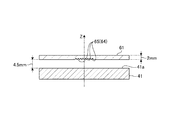
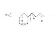
ここで、図8〜図11を参照して表示装置1に関する輝度実測試験について説明する。ここでは、以上で説明した実施形態に係る表示装置1を用いて透明文字板61における輝度を、輝度測定用カメラによって実測する輝度実測試験を実施した。ここで、表示装置1では、図8に示すような配置となるように、ディスプレイ41、透明文字板61等を配置すると共に、図9に示すような形状となるように、溝65を形成した。すなわち、当該表示装置1では、透明文字板61の奥行き方向の厚さを2mmとし、ディスプレイ41の画像表示面(表面)41aと当該透明文字板61の裏面(背面)との奥行き方向の間隔を4.5mmとした。そして、当該表示装置1では、透明文字板61の背面に、図柄64を構成する溝65を形成した。本輝度実測試験におけるZ方向(奥行き方向)に対する輝度測定位置は、当該透明文字板61の溝65が形成された面上の位置であり、輝度測定用カメラの焦点位置に相当する。そして、当該表示装置1では、溝65を略V字状の断面形状で、かつ、0.5μmピッチで形成し、各溝65の奥行き方向の深さを0.25μmとし、底部がなす角度をほぼ90°(deg)とした。また、当該表示装置1では、各溝65を一方向に延在する直線溝として形成した。本輝度実測試験におけるX方向(幅方向)及びY方向(鉛直方向)に対する輝度測定位置は、図10に示すように、図柄64の領域と図柄64の周囲の領域とでそれぞれ複数の位置を選定しこれらの平均値を用いた。また、ディスプレイ41の光源色の点灯条件としては、色度図におけるX=0.63、Y=0.35の赤色の光、X=0.31、Y=0.58の緑色の光、X=0.14、Y=0.05の青色の光を用いてそれぞれ輝度実測試験を実施した。本輝度実測試験では、光源62を消灯した状態で、画像表示面41aに対して透明文字板61を相対回転させ偏光方向L3と延在方向L1とがなす角度θを変更させながら、上述した輝度測定位置で輝度測定用カメラを用いて輝度を実測した。   Here, the brightness measurement test for the display device 1 will be described with reference to FIGS. Here, a luminance measurement test was performed in which the luminance of the transparent dial 61 was measured with a luminance measurement camera using the display device 1 according to the embodiment described above. Here, in the display device 1, the display 41, the transparent dial 61, and the like are arranged so as to have the arrangement shown in FIG. 8, and the groove 65 is formed so as to have the shape shown in FIG. 9. . That is, in the display device 1, the thickness of the transparent dial 61 in the depth direction is 2 mm, and the distance in the depth direction between the image display surface (front surface) 41 a of the display 41 and the rear surface (back surface) of the transparent dial 61 is set. It was 4.5 mm. And in the said display apparatus 1, the groove | channel 65 which comprises the pattern 64 was formed in the back surface of the transparent dial 61. FIG. The luminance measurement position with respect to the Z direction (depth direction) in the luminance measurement test is a position on the surface of the transparent dial 61 where the groove 65 is formed, and corresponds to the focal position of the luminance measurement camera. And in the said display apparatus 1, the groove | channel 65 is formed in a substantially V-shaped cross-sectional shape and 0.5 micrometer pitch, the depth of the depth direction of each groove | channel 65 shall be 0.25 micrometer, and the angle which a bottom part makes is made. The angle was approximately 90 ° (deg). In the display device 1, each groove 65 is formed as a linear groove extending in one direction. As shown in FIG. 10, a plurality of positions are selected for the luminance measurement positions in the X direction (width direction) and the Y direction (vertical direction) in the luminance measurement test, as shown in FIG. These average values were used. The lighting conditions of the light source color of the display 41 include red light with X = 0.63 and Y = 0.35 in the chromaticity diagram, green light with X = 0.31 and Y = 0.58, X = 0.14, Y = 0.05 was used, and the brightness | luminance measurement test was implemented, respectively. In this luminance measurement test, the above-described luminance is obtained by changing the angle θ between the polarization direction L3 and the extending direction L1 by rotating the transparent dial 61 relative to the image display surface 41a with the light source 62 turned off. The luminance was measured at the measurement position using a luminance measurement camera.

図11は、上記の輝度実測試験の結果を表している。図11は、横軸を偏光方向L3と延在方向L1とがなす角度θ[deg]とし、縦軸を図柄64の周囲の領域の輝度に対する図柄64の領域の輝度の輝度比[%]としている。図11からも明らかなように、表示装置1は、偏光方向L3と延在方向L1とがなす角度θが[75°≦θ≦105°]の範囲内にある場合、赤(線R参照)、緑(線G参照)、青(線B参照)の3色すべてにおいて、図柄64の周囲の領域に対する図柄64の領域の輝度比が90%以上100%以下となり、図柄64を非表示とした場合に、透明文字板61上の図柄64を構成する溝65を視認されにくくすることができることが明らかである。さらには、表示装置1は、角度θが[85°≦θ≦95°]の範囲内にある場合、赤、緑、青の3色すべてにおいて、図柄64の周囲の領域に対する図柄64の領域の輝度比が92.5%以上100%以下となり、溝65をさらに視認されにくくすることができることが明らかである。そして、表示装置1は、角度θが[θ=90°]である場合、すなわち、偏光方向L3と延在方向L1とが直交する場合に、赤、緑、青の3色すべてにおいて、図柄64の周囲の領域に対する図柄64の領域の輝度比が最大となり、溝65を最も視認されにくくすることができることが明らかである。ここでは、表示装置1は、角度θが[θ=90°]である場合、赤色の光を照射した場合の輝度比が97.4%、緑色の光を照射した場合の輝度比が97.6%、青色の光を照射した場合の輝度比が94%となった。   FIG. 11 shows the result of the luminance measurement test. In FIG. 11, the horizontal axis represents the angle θ [deg] formed by the polarization direction L3 and the extending direction L1, and the vertical axis represents the luminance ratio [%] of the luminance of the region of the symbol 64 to the luminance of the region around the symbol 64. Yes. As is apparent from FIG. 11, the display device 1 is red (see the line R) when the angle θ formed by the polarization direction L3 and the extending direction L1 is within the range of [75 ° ≦ θ ≦ 105 °]. In all three colors, green (see line G) and blue (see line B), the luminance ratio of the area of the pattern 64 to the area around the pattern 64 is 90% to 100%, and the pattern 64 is not displayed. In this case, it is clear that the grooves 65 constituting the symbol 64 on the transparent dial 61 can be made difficult to be visually recognized. Furthermore, when the angle θ is within the range of [85 ° ≦ θ ≦ 95 °], the display device 1 can display the region of the pattern 64 with respect to the region around the symbol 64 in all three colors of red, green, and blue. It is apparent that the luminance ratio is 92.5% or more and 100% or less, and the groove 65 can be further hardly seen. When the angle θ is [θ = 90 °], that is, when the polarization direction L3 and the extending direction L1 are orthogonal to each other, the display device 1 has the design 64 in all three colors of red, green, and blue. It is apparent that the luminance ratio of the area of the pattern 64 to the area around the maximum is the largest, and the groove 65 can be made most difficult to be visually recognized. Here, when the angle θ is [θ = 90 °], the display device 1 has a luminance ratio of 97.4% when irradiated with red light and a luminance ratio of 97. 9 when irradiated with green light. The luminance ratio when irradiated with 6% blue light was 94%.

なお、本実施形態の表示装置1は、上述したように溝65の延在方向L1と前面側表示装置6の光源62による光の照射方向L2とが直交するように構成される。つまりここでは、背面側表示装置4の偏光方向L3、及び、光源62による光の照射方向L2は、鉛直方向に沿った方向であり、溝65の延在方向L1は、水平方向に沿った方向である。したがって、表示装置1は、光源62からの光を、図柄64を構成する溝65に対してほぼ垂直に入射するようにすることができるので、透明文字板61上に図柄64を表示する場合に、溝65で前面側(運転席側)に反射される光の量を相対的に増加させることができ、当該図柄64を鮮明に表示することができる。   In addition, the display apparatus 1 of this embodiment is comprised so that the extending direction L1 of the groove | channel 65 and the light irradiation direction L2 by the light source 62 of the front side display apparatus 6 may orthogonally cross as mentioned above. That is, here, the polarization direction L3 of the rear display device 4 and the light irradiation direction L2 of the light source 62 are directions along the vertical direction, and the extending direction L1 of the groove 65 is a direction along the horizontal direction. It is. Therefore, the display device 1 can cause the light from the light source 62 to be incident substantially perpendicular to the groove 65 constituting the symbol 64, so that the symbol 64 is displayed on the transparent dial 61. The amount of light reflected by the groove 65 on the front side (driver's seat side) can be relatively increased, and the symbol 64 can be clearly displayed.

本実施形態の第2表示面12は、透明文字板61の背面側の主面に、延在方向L1、照射方向L2、偏光方向L3等が上記のような位置関係となるように複数の微細な溝65が形成されることで、図柄64の表示構造66(図6参照)、及び、非表示構造67(図6参照)が構成される。   The second display surface 12 of the present embodiment has a plurality of fine patterns such that the extending direction L1, the irradiation direction L2, the polarization direction L3, and the like are in the positional relationship as described above on the main surface on the back side of the transparent dial 61. By forming the groove 65, the display structure 66 (see FIG. 6) of the symbol 64 and the non-display structure 67 (see FIG. 6) are configured.

ここで、第2表示面12の表示構造66とは、第2表示面12の表示状態にて光源62から照射される光によって図柄64を形成するための構造である。ここでは、表示構造66は、第2表示面12の表示状態にて、光源62から照射された光を、第2表示面12を構成する部材である透明文字板61の表面に形成された複数の微細な溝65で反射させることで図柄64を形成する構造である。これにより、表示構造66は、運転者等が第2表示面12上の図柄64を視認可能な状態とすることができる。   Here, the display structure 66 of the second display surface 12 is a structure for forming the symbol 64 by light emitted from the light source 62 in the display state of the second display surface 12. Here, the display structure 66 has a plurality of light beams emitted from the light source 62 in the display state of the second display surface 12 formed on the surface of the transparent dial 61 that is a member constituting the second display surface 12. The pattern 64 is formed by being reflected by the fine groove 65. Thereby, the display structure 66 can make the driver | operator etc. the state which can visually recognize the symbol 64 on the 2nd display surface 12. FIG.

一方、第2表示面12の非表示構造67とは、第2表示面12の非表示状態にて表示状態と比較して図柄64を視認しに難くするための構造である。さらに言えば、第2表示面12の非表示構造67とは、第2表示面12の非表示状態にて、表示状態と比較して複数の微細な溝65を視認しに難くするための構造である。ここでは、非表示構造67は、光源62が消灯することで図柄64を視認しに難くすると共に、さらに、背面側表示装置4の偏光方向L3と図柄64を構成する溝65の延在方向L1とが所定の角度範囲、典型的には、上記のように75°以上105°以下の角度範囲で交差するように溝65を形成することで、溝65自体も視認しに難くする構造である。これにより、非表示構造67は、第2表示面12上の図柄64の領域と図柄64の周囲の領域とで透過光の振幅がほぼ同等となるようにし、図柄64の領域と図柄64の周囲の領域との輝度に差がほぼない状態とすることができ、これにより、非表示状態にて、図柄64、及び、これを構成する複数の微細な溝65を視認しに難くすることができる。   On the other hand, the non-display structure 67 of the second display surface 12 is a structure for making it difficult to visually recognize the symbol 64 in the non-display state of the second display surface 12 compared to the display state. Furthermore, the non-display structure 67 of the second display surface 12 is a structure for making it difficult to visually recognize the plurality of fine grooves 65 in the non-display state of the second display surface 12 compared to the display state. It is. Here, the non-display structure 67 makes it difficult to visually recognize the pattern 64 by turning off the light source 62, and further, the polarization direction L3 of the back side display device 4 and the extending direction L1 of the groove 65 constituting the pattern 64. And the groove 65 itself is difficult to visually recognize by forming the groove 65 so as to intersect within a predetermined angle range, typically, an angle range of 75 ° to 105 ° as described above. . Thereby, the non-display structure 67 is configured so that the amplitude of the transmitted light is almost equal between the area of the symbol 64 on the second display surface 12 and the area around the symbol 64, and the area around the symbol 64 and the area around the symbol 64. Thus, it is possible to make it difficult to visually recognize the pattern 64 and the plurality of fine grooves 65 constituting the same in the non-display state. .

上記のように構成される表示装置1は、第1表示面11と第2表示面12とによって情報を表示する。より詳細には、第1表示面11と第2表示面12は、第1表示面11に表示される車両情報と第2表示面12に描かれた図柄64とを連携させた少なくとも1つの情報を表示する。ここで、車両情報と図柄64とを連携させた情報とは、典型的には、第1表示面11の車両情報又は第2表示面12の図柄64のいずれか一方では情報として意味をなさない情報であり、当該車両情報と当該図柄64とを組み合わせて連携させることではじめて情報として意味をなす情報である。つまりここでは、車両情報と図柄64とは、それぞれでは意味をなさないものの、相互に組み合わせることではじめて相互に連携した情報として意味をなすものであり、意味をなす連携した情報を生成するためにはいずれも必要不可欠なものである。   The display device 1 configured as described above displays information on the first display surface 11 and the second display surface 12. More specifically, the first display surface 11 and the second display surface 12 are at least one piece of information in which the vehicle information displayed on the first display surface 11 and the symbol 64 drawn on the second display surface 12 are linked. Is displayed. Here, the information in which the vehicle information and the symbol 64 are linked is typically meaningless as information on either the vehicle information on the first display surface 11 or the symbol 64 on the second display surface 12. It is information that is meaningful as information only when the vehicle information and the symbol 64 are combined and linked. That is, here, the vehicle information and the symbol 64 are meaningless as information linked to each other only when they are combined with each other, although the vehicle information and the symbol 64 do not make any sense in order to generate linked information that makes sense. Are indispensable.

具体的には、表示装置1は、前面側表示装置6の各光源62が点灯した状態、すなわち、第2表示面12の全体が表示状態である場合には、例えば、図1に例示するような表示態様となる。   Specifically, the display device 1 is illustrated in FIG. 1 when the light sources 62 of the front side display device 6 are turned on, that is, when the entire second display surface 12 is in the display state, for example. Display mode.

この場合、表示装置1は、ディスプレイ41と前面側表示装置6のメイン透明文字板61Aとが速度計を構成する。つまり、表示装置1は、ディスプレイ41(第1表示面11)に表示される車両情報に関する画像、ここでは指針画像41b、速度計小目盛画像41cと、メイン透明文字板61A(第2表示面12)に描かれ点灯表示された速度計大目盛図柄64Aとが組み合わされて連携し、車両の車速を表示する。表示装置1は、第1表示面11に指針画像41bを動的に回動させる動画を表示し、当該指針画像41bによって、速度計小目盛画像41c、速度計大目盛図柄64Aにおける現在の速度を指し示すことで、現在の車速を表示する。   In this case, in the display device 1, the display 41 and the main transparent dial 61 </ b> A of the front side display device 6 constitute a speedometer. That is, the display device 1 includes an image relating to vehicle information displayed on the display 41 (first display surface 11), here, a pointer image 41b, a speedometer small scale image 41c, and a main transparent dial 61A (second display surface 12). ) And the speedometer large scale symbol 64A, which is lit and displayed, cooperate with each other to display the vehicle speed of the vehicle. The display device 1 displays a moving image that dynamically rotates the pointer image 41b on the first display surface 11, and the current speed of the speedometer small scale image 41c and the speedometer large scale symbol 64A is displayed by the pointer image 41b. The current vehicle speed is displayed by pointing.

また、表示装置1は、回転計セグメント表示部42Aと前面側表示装置6のサブ透明文字板61Bとが回転計を構成する。つまり、表示装置1は、回転計セグメント表示部42A(第1表示面11)に表示される車両情報、ここでは回転計セグメントバー52Aと、サブ透明文字板61B(第2表示面12)に描かれ点灯表示された回転計目盛図柄64Bとが組み合わされて連携し、車両のエンジン回転数を表示する。表示装置1は、複数の回転計セグメントバー52Aに対応する各光源42aを現在のエンジン回転数に応じて点灯、消灯させ、回転計目盛図柄64Bにおける現在のエンジン回転数の位置まで回転計セグメントバー52Aを点灯表示することで、現在のエンジン回転数を表示する。同様に、表示装置1は、水温計セグメント表示部42Bと前面側表示装置6のサブ透明文字板61Cとが水温計を構成し、燃料計セグメント表示部42Cと前面側表示装置6のサブ透明文字板61Cとが燃料計を構成する。これら水温計、燃料計の動作は、上述の回転計とほぼ同様なのでその説明を省略する。   In the display device 1, the tachometer segment display portion 42 </ b> A and the sub transparent dial 61 </ b> B of the front side display device 6 constitute a tachometer. That is, the display device 1 draws vehicle information displayed on the tachometer segment display unit 42A (first display surface 11), here, the tachometer segment bar 52A and the sub transparent dial 61B (second display surface 12). The tachometer scale symbol 64B that is lit and displayed is combined and linked to display the engine speed of the vehicle. The display device 1 turns on and off the light sources 42a corresponding to the plurality of tachometer segment bars 52A according to the current engine speed, and reaches the position of the current engine speed on the tachometer scale symbol 64B. The current engine speed is displayed by lighting 52A. Similarly, in the display device 1, the water temperature meter segment display unit 42B and the sub transparent dial 61C of the front side display device 6 constitute a water temperature meter, and the fuel meter segment display unit 42C and the sub transparent character of the front side display device 6 The plate 61C constitutes a fuel gauge. Since the operation of the water temperature gauge and fuel gauge is almost the same as that of the above-described tachometer, the description thereof is omitted.

一方、表示装置1は、前面側表示装置6の各光源62の少なくとも一部が消灯した状態、すなわち、第2表示面12の一部が非表示状態である場合には、例えば、図12に例示するような表示態様となる。図12は、メイン透明文字板61Aの端面に設けられた各光源62が消灯状態であり、すなわち、第2表示面12において速度計大目盛図柄64Aが描かれたメイン透明文字板61Aの部分が非表示状態となった状態を示している。この場合、表示装置1は、メイン透明文字板61Aの端面に設けられた各光源62を消灯状態とし第2表示面12の速度計大目盛図柄64Aを非表示状態とすることで、第1表示面11の画像表示面41aの表示領域全体を使ったフルサイズの車両情報の表示が可能となる。図12の例では、表示装置1は、一例として、画像表示面41aの表示領域全体を使ったナビゲーション画像を表示している。このとき、表示装置1は、速度計大目盛図柄64A等を構成する微細な溝65の延在方向L1と背面側表示装置4の光の照射方向L2とが所定の角度で交差するように構成されていることから、速度計大目盛図柄64Aを構成する溝65を非表示状態においてより見え難くすることができるので、第1表示面11で表示されている車両情報の視認性を向上することができる。なお、表示装置1は、サブ透明文字板61B、61Cの端面に設けられた各光源62を消灯状態とすることで第2表示面12の回転計目盛図柄64B、水温計目盛図柄64C、燃料計目盛図柄64Dを非表示状態とすることもできる。   On the other hand, in the display device 1, when at least a part of each light source 62 of the front side display device 6 is turned off, that is, when a part of the second display surface 12 is in a non-display state, for example, FIG. The display mode is as illustrated. FIG. 12 shows that each light source 62 provided on the end surface of the main transparent dial 61A is in the off state, that is, the portion of the main transparent dial 61A on which the speedometer large scale symbol 64A is drawn on the second display surface 12 is shown. The state which became the non-display state is shown. In this case, the display device 1 turns off each light source 62 provided on the end face of the main transparent dial 61A and puts the speedometer large scale symbol 64A on the second display surface 12 into a non-display state. The full size vehicle information can be displayed using the entire display area of the image display surface 41a of the surface 11. In the example of FIG. 12, the display device 1 displays a navigation image using the entire display area of the image display surface 41a as an example. At this time, the display device 1 is configured such that the extending direction L1 of the fine groove 65 constituting the speedometer large scale symbol 64A and the like and the light irradiation direction L2 of the rear side display device 4 intersect at a predetermined angle. Therefore, it is possible to make the groove 65 constituting the speedometer large scale symbol 64A more difficult to see in the non-display state, so that the visibility of the vehicle information displayed on the first display surface 11 is improved. Can do. The display device 1 turns off the light sources 62 provided on the end surfaces of the sub transparent dials 61B and 61C so that the tachometer scale symbol 64B, the water temperature gauge symbol pattern 64C, and the fuel meter on the second display surface 12 are displayed. The scale symbol 64D can be in a non-display state.

以上で説明した表示装置1によれば、車両情報を表示する第1表示面11と、第1表示面11に重ねて設けられ光を透過すると共に、第1表示面11との積層方向に沿って視て第1表示面11の表示領域内と表示領域外とにまたがって描かれた図柄64を有し、当該図柄64を表示する表示状態と、当該図柄64を非表示とする非表示状態とに切り替え可能である第2表示面12とを備え、第1表示面11と第2表示面12とによって情報を表示する。   According to the display device 1 described above, the first display surface 11 that displays vehicle information and the first display surface 11 are provided so as to transmit light and along the stacking direction with the first display surface 11. A display state in which the design 64 is drawn across the display area and the outside of the display area of the first display surface 11 and the design 64 is displayed, and a non-display state in which the design 64 is not displayed. And a second display surface 12 that can be switched to and displays information on the first display surface 11 and the second display surface 12.

したがって、表示装置1は、第1表示面11に表示される車両情報と、第1表示面11に重ねて設けられ光を透過する第2表示面12に表示される図柄64とを組み合わせて情報を表示することができる。これにより、表示装置1は、第1表示面11の車両情報と第2表示面12の図柄64とが組み合わせられた立体的で斬新な見栄えの表示を行うことができる。この場合、表示装置1は、第1表示面11に重ねて設けられる第2表示面12が光を透過し、かつ、図柄64の表示、非表示を切り替え可能に構成されることで、図柄64を非表示とすることで第1表示面11の表示領域を広く使って車両情報を表示することもできる。これにより、表示装置1は、様々な態様の表示を臨機応変に行うことができる。そしてさらに、表示装置1は、第2表示面12の図柄64が第1表示面11の表示領域内と表示領域外とにまたがるように描かれているので、第1表示面11の表示領域外のより広い領域に図柄64を表示することができる。この結果、表示装置1は、第1表示面11の車両情報と第2表示面12の図柄64とで全体として表示領域を相対的に大きく見せる視覚効果を得ることができる。これにより、表示装置1は、デザイン自由度の高い多様な表示を行うことができる。   Therefore, the display device 1 combines the vehicle information displayed on the first display surface 11 and the symbol 64 displayed on the second display surface 12 that is provided on the first display surface 11 and transmits light. Can be displayed. Thereby, the display device 1 can perform a stereoscopic and novel appearance display in which the vehicle information on the first display surface 11 and the symbol 64 on the second display surface 12 are combined. In this case, the display device 1 is configured such that the second display surface 12 provided to overlap the first display surface 11 transmits light, and the display 64 can be switched between display and non-display. By not displaying the vehicle information, the vehicle information can be displayed using a wide display area of the first display surface 11. Thereby, the display apparatus 1 can perform display of various aspects flexibly. Further, the display device 1 is drawn so that the pattern 64 of the second display surface 12 extends over the display region of the first display surface 11 and the outside of the display region. The pattern 64 can be displayed in a wider area. As a result, the display device 1 can obtain a visual effect that makes the display area relatively large as a whole by the vehicle information on the first display surface 11 and the symbol 64 on the second display surface 12. Thereby, the display apparatus 1 can perform various displays with high design freedom.

さらに、以上で説明した表示装置1によれば、第1表示面11と第2表示面12とは、車両情報と図柄64とを連携させた少なくとも1つの情報を表示する。したがって、表示装置1は、第1表示面11の車両情報と第2表示面12の図柄64とを組み合わせて一体感のある情報を運転者等に提示することができる。   Furthermore, according to the display device 1 described above, the first display surface 11 and the second display surface 12 display at least one information in which the vehicle information and the symbol 64 are linked. Therefore, the display device 1 can present information with a sense of unity to the driver or the like by combining the vehicle information on the first display surface 11 and the symbol 64 on the second display surface 12.

さらに、以上で説明した表示装置1によれば、第1表示面11は、矩形状の表示領域を含み、図柄64は、第1表示面11の矩形状の表示領域内から表示領域外に張り出した円弧状の部分64aを含む。したがって、表示装置1は、ディスプレイ41等の矩形状の表示領域のイメージにとらわれない斬新な見栄えとすることができる。   Furthermore, according to the display device 1 described above, the first display surface 11 includes a rectangular display region, and the pattern 64 extends from the rectangular display region of the first display surface 11 to the outside of the display region. A circular arc portion 64a is included. Therefore, the display device 1 can have a novel appearance that is not constrained by an image of a rectangular display area such as the display 41.

さらに、以上で説明した表示装置1によれば、第1表示面11は、車両情報として指針画像41bを表示し、図柄64は、指針画像41bの周りに設けられ当該指針画像41bによって指し示される速度計大目盛図柄64Aを含んで構成される。したがって、表示装置1は、指針画像41bと速度計大目盛図柄64Aとを組み合わせることで車両に関する種々の計測値(ここでは車速)を表示することができる。   Furthermore, according to the display device 1 described above, the first display surface 11 displays the pointer image 41b as vehicle information, and the pattern 64 is provided around the pointer image 41b and pointed to by the pointer image 41b. It is comprised including the speedometer large scale symbol 64A. Therefore, the display device 1 can display various measurement values (here, vehicle speed) relating to the vehicle by combining the pointer image 41b and the speedometer large scale symbol 64A.

さらに、以上で説明した表示装置1によれば、第2表示面12は、図柄64を構成する凹凸部(ここでは溝65)が形成され、光源62から照射される光によって図柄64を表示する表示状態と、光源62が消灯することで図柄64を非表示とする非表示状態とを切り替え可能である。したがって、表示装置1は、第2表示面12の表示状態にて、光源62から照射された光を、凹凸部で反射させることで図柄64を形成することができると共に、光源62を消灯することで当該図柄64を非表示状態とすることができる。   Furthermore, according to the display device 1 described above, the second display surface 12 is formed with the concave and convex portions (here, the grooves 65) constituting the pattern 64, and displays the pattern 64 by the light emitted from the light source 62. It is possible to switch between the display state and the non-display state in which the symbol 64 is not displayed when the light source 62 is turned off. Therefore, the display device 1 can form the pattern 64 by reflecting the light emitted from the light source 62 by the uneven portion in the display state of the second display surface 12 and turn off the light source 62. Thus, the symbol 64 can be in a non-display state.

さらに、以上で説明した表示装置1によれば、第1表示面11は、一方向に偏光された光によって車両情報に関する画像を表示し、凹凸部は、第2表示面12に形成され偏向された光の偏光方向L3と交差する方向に延在する溝65である。ここでは、溝65の延在方向L1と偏光方向L3とは、上述の角度範囲で交差する。   Furthermore, according to the display device 1 described above, the first display surface 11 displays an image related to vehicle information by light polarized in one direction, and the uneven portion is formed on the second display surface 12 and deflected. The groove 65 extends in a direction crossing the polarization direction L3 of the light. Here, the extending direction L1 of the groove 65 and the polarization direction L3 intersect in the above-described angle range.

したがって、表示装置1は、光源62から照射された光を、図柄64を構成する溝65で反射させることで、第2表示面12に当該図柄64を表示することができる一方、光源62を消灯することで当該図柄64を非表示とすることができる。これにより、表示装置1は、第1表示面11の前面側に図柄64の意匠を表示し、背景の第1表示面11上の車両情報と図柄64の意匠とを立体的に組み合わせて表示できるので、上記のように立体的で斬新な表示を行うことができる。その上で、表示装置1は、微細な溝65によって図柄64が構成される前面側表示装置6において、光源62の消灯時に図柄64の意匠が見えにくくなり、透明文字板61の背景の第1表示面11を見通すことができ、必要に応じて光源62の点灯時に図柄64の意匠が現れるようにすることができる。そして、表示装置1は、上記のように非表示状態で図柄64を構成する溝65を見えにくい構造とし、適正な視認性を確保することができる。   Therefore, the display device 1 can display the symbol 64 on the second display surface 12 by reflecting the light emitted from the light source 62 by the groove 65 constituting the symbol 64, while turning off the light source 62. By doing so, the symbol 64 can be hidden. Thereby, the display apparatus 1 can display the design of the design 64 on the front side of the first display surface 11 and display the vehicle information on the first display surface 11 of the background and the design of the design 64 in a three-dimensional combination. Therefore, a three-dimensional and novel display can be performed as described above. In addition, in the display device 1, the design of the design 64 becomes difficult to see when the light source 62 is turned off in the front display device 6 in which the design 64 is configured by the fine grooves 65, and the first background of the transparent dial 61 is displayed. The display surface 11 can be seen through, and the design of the pattern 64 can appear when the light source 62 is turned on as necessary. And the display apparatus 1 makes it difficult to see the groove | channel 65 which comprises the pattern 64 in a non-display state as mentioned above, and can ensure appropriate visibility.

なお、上述した本発明の実施形態に係る表示装置は、上述した実施形態に限定されず、特許請求の範囲に記載された範囲で種々の変更が可能である。   The display device according to the above-described embodiment of the present invention is not limited to the above-described embodiment, and various modifications can be made within the scope described in the claims.

以上の説明では、ディスプレイ41は、1つで構成されるものとして説明したが2つ以上が組み合わせられて構成されてもよい。以上で説明した表示装置1は、例えば、ディスプレイ41の偏光方向L3が鉛直方向に対して傾斜していてもよく、この場合であっても偏光方向L3と延在方向L1とが上記のような関係になっていればよい。   In the above description, the display 41 has been described as being configured by one, but may be configured by combining two or more. In the display device 1 described above, for example, the polarization direction L3 of the display 41 may be inclined with respect to the vertical direction. Even in this case, the polarization direction L3 and the extending direction L1 are as described above. It only has to be a relationship.

以上の説明では、セグメント表示部42は、複数の光源42aと文字板5に描かれたセグメントバー52とを含んで構成されるものとして説明したがこれに限らない。例えば、図13に示すように、変形例1に係る表示装置201が備えるセグメント表示部242は、液晶ディスプレイ243等を含んで構成され、当該液晶ディスプレイ243の画像表示面243aにセグメントバー52(図1等参照)の画像を表示することで構成されてもよい。この場合、当該画像表示面243aは、第1表示面11の一部を構成することとなる。またこの場合、表示装置201は、典型的には、液晶ディスプレイ243の最終的な偏光方向が偏光方向L3に合わせられる。また、セグメント表示部は、ドットマトリックス等を含んで構成されてもよい。   In the above description, the segment display unit 42 has been described as including a plurality of light sources 42 a and the segment bar 52 drawn on the dial 5, but is not limited thereto. For example, as shown in FIG. 13, the segment display unit 242 included in the display device 201 according to the modification 1 includes a liquid crystal display 243 and the like, and the segment bar 52 (see FIG. 13) is displayed on the image display surface 243a of the liquid crystal display 243. 1) and the like. In this case, the image display surface 243a constitutes a part of the first display surface 11. In this case, the display device 201 typically matches the final polarization direction of the liquid crystal display 243 with the polarization direction L3. Further, the segment display unit may be configured to include a dot matrix or the like.

以上の説明では、背面側表示装置4は、ディスプレイ41とセグメント表示部42とを含んで構成されるものとして説明したが、これらにかえて、あるいは、これらに加えてアナログ計器等を含んで構成されてもよい。この場合、第1表示面11は、表示領域を構成するアナログ計器、及び、その文字板の表面(奥行き方向前面側の面)を含んで構成される。またこの場合、表示装置1は、アナログ計器の光源と、溝65が形成される部材である透明文字板61との間に、当該アナログ計器の光源からの光を、一方向(ここでは、偏光方向L3)に偏光された光にする偏光板を備えていてもよい。この場合であっても、表示装置1は、溝65が偏向された光の偏光方向L3と交差する方向に延在するようにして形成されることで、第2表示面12の非表示状態で図柄64を構成する溝65を見えにくい構造とすることができる。   In the above description, the rear side display device 4 has been described as including the display 41 and the segment display unit 42. However, instead of these, or in addition to these, an analog instrument or the like is included. May be. In this case, the 1st display surface 11 is comprised including the analog instrument which comprises a display area, and the surface (surface of the depth direction front side) of the dial. In this case, the display device 1 transmits light from the light source of the analog instrument in one direction (here, polarized light) between the light source of the analog instrument and the transparent dial 61 that is a member in which the groove 65 is formed. There may be provided a polarizing plate that makes light polarized in the direction L3). Even in this case, the display device 1 is formed so that the groove 65 extends in a direction crossing the polarization direction L3 of the deflected light, so that the second display surface 12 is not displayed. The groove 65 constituting the pattern 64 can be made difficult to see.

また、以上の説明では、第1表示面11は、矩形状の表示領域を含み、図柄64は、第1表示面11の矩形状の表示領域内から表示領域外に張り出した円弧状の部分64aを含むものとして説明したがこれに限らない。例えば、速度計大目盛図柄64Aは、正円状に形成された円環の部分が画像表示面41aの表示領域の鉛直方向上側、及び、下側の両側にはみ出るようにして当該表示領域内と表示領域外とにまたがって描かれるものとして説明したがこれ限らない。速度計大目盛図柄64Aは、例えば、円環の部分が楕円形状でもよいし、正円形状や楕円形状の一部が切り欠かれたような円弧形状であってもよい。また、図柄64は、画像表示面41aの表示領域の幅方向左右にはみ出るようにして描かれた図柄を含んでもよい。また、図柄64は、速度計小目盛画像41cに相当する図柄を含んで構成されてもよい。   In the above description, the first display surface 11 includes a rectangular display area, and the design 64 has an arc-shaped portion 64 a that protrudes from the rectangular display area of the first display surface 11 to the outside of the display area. However, the present invention is not limited to this. For example, the speedometer large scale symbol 64A has a shape of a circular ring formed in a perfect circle shape so that it protrudes from the display area of the image display surface 41a in the vertical direction upper side and the lower side. Although described as being drawn across the display area, this is not restrictive. The speedometer large scale symbol 64A may be, for example, an oval shape in a ring shape, or an arc shape in which a part of a perfect circle shape or an oval shape is cut out. Further, the symbol 64 may include a symbol drawn so as to protrude right and left in the width direction of the display area of the image display surface 41a. Further, the symbol 64 may include a symbol corresponding to the speedometer small scale image 41c.

また、以上の説明では、背面側表示装置4と前面側表示装置6とによって速度計、回転計、水温計、燃料計を構成するものとして説明したがこれに限らない。つまり、第1表示面11は、車両情報として、指針画像41b、速度計小目盛画像41c、セグメントバー52を表示し、第2表示面12は、図柄64として、速度計大目盛図柄64A、回転計目盛図柄64B、水温計目盛図柄64C、燃料計目盛図柄64Dを有するものとして説明したがこれに限らない。第2表示面12に描かれる図柄64は、第1表示面11の表示領域内と表示領域外とにまたがって描かれるものであればよく、例えば、エコ走行に関する図柄、警告(ワーニング)を表す図柄、車の形状を模した図柄(アイコン)等であってもよく、形状も様々な形状であってよい。例えば、表示装置1、201は、第2表示面12に図柄64として、車の形状を模した図柄を設けると共に、第1表示面11を構成する画像表示面41aに車両情報として、開放されているドアの位置の画像を表示させ、これらを重ねて表示することで、車両情報と図柄64とを連携させて車両におけるドア開位置に関する情報を表示するようにしてもよい。   In the above description, the rear display device 4 and the front display device 6 are described as constituting a speedometer, a tachometer, a water temperature meter, and a fuel meter, but the present invention is not limited thereto. That is, the first display surface 11 displays a pointer image 41b, a speedometer small scale image 41c, and a segment bar 52 as vehicle information, and the second display surface 12 has a speedometer large scale symbol 64A as a symbol 64, and a rotation. Although it demonstrated as having the scale scale symbol 64B, the water temperature scale scale symbol 64C, and the fuel gauge scale symbol 64D, it is not restricted to this. The symbol 64 drawn on the second display surface 12 only needs to be drawn across the display area and the outside of the display area of the first display surface 11, and represents, for example, a symbol and warning (warning) regarding eco-driving. It may be a symbol, a symbol (icon) imitating the shape of a car, or the like, and the shape may be various. For example, the display devices 1 and 201 are provided with a symbol imitating the shape of a car as a symbol 64 on the second display surface 12 and opened as vehicle information on the image display surface 41a constituting the first display surface 11. By displaying an image of the position of the existing door and displaying them in an overlapping manner, the vehicle information and the symbol 64 may be linked to display information on the door opening position in the vehicle.

図14は、変形例2に係る表示装置の奥行き方向前面側の正面図である。例えば、図14に示す変形例に係る表示装置301は、背面側表示装置4にかえて背面側表示装置304を備えると共に、前面側表示装置6にかえて前面側表示装置306を備え、背面側表示装置304と前面側表示装置306とが奥行き方向に重なって設けられることで、ツーレイヤー式表示装置を構成する。   FIG. 14 is a front view of the front side in the depth direction of the display device according to the second modification. For example, the display device 301 according to the modification shown in FIG. 14 includes a back side display device 304 instead of the back side display device 4, and includes a front side display device 306 instead of the front side display device 6. The display device 304 and the front side display device 306 are provided so as to overlap each other in the depth direction, thereby forming a two-layer display device.

本変形例の背面側表示装置304は、ディスプレイ341と、第1アナログ計器(例えば、速度計)342と、第2アナログ計器(例えば、回転計)343とを含んで構成される。背面側表示装置304は、第1アナログ計器342が幅方向左側に配置される一方、第2アナログ計器343が幅方向右側に配置され、さらに、ディスプレイ341がこれらの間に配置される。ディスプレイ341は、上述のディスプレイ41と同様に、画像表示面341aに種々の車両情報に関する画像を表示するものであり、例えば、薄型の液晶ディスプレイを用いることができるが、これに限らず、プラズマディスプレイ、有機ELディスプレイ等を用いることもできる。そして、本変形例に係る表示装置301において、第1層目の表示面である第1表示面311は、文字板5の開口部351から露出したディスプレイ341の画像表示面341aが形成された面によって構成される。すなわち、第1表示面311は、略矩形状に形成された画像表示面341aの表示領域を含む。   The back side display device 304 of this modification includes a display 341, a first analog instrument (for example, a speedometer) 342, and a second analog instrument (for example, a tachometer) 343. In the rear side display device 304, the first analog instrument 342 is disposed on the left side in the width direction, the second analog instrument 343 is disposed on the right side in the width direction, and the display 341 is disposed therebetween. The display 341 displays an image related to various vehicle information on the image display surface 341a in the same manner as the display 41 described above. For example, a thin liquid crystal display can be used, but the present invention is not limited to this. An organic EL display or the like can also be used. In the display device 301 according to this modification, the first display surface 311 that is the display surface of the first layer is a surface on which the image display surface 341a of the display 341 exposed from the opening 351 of the dial plate 5 is formed. Consists of. That is, the first display surface 311 includes a display area of the image display surface 341a formed in a substantially rectangular shape.

また、本変形例の前面側表示装置306は、透明文字板61にかえて透明文字板361を備える。透明文字板361は、上述の透明文字板61と同様に、背面側表示装置304の前面側、さらに言えば、文字板5の前面側に重ねて設けられる。透明文字板361は、上述の透明文字板61と同様に、ディスプレイ341から照射された光を透過する透過性を有する透明部材(透明媒体)によって形成される透明導光板である。ただし、以上で説明した透明導光板61は、メイン透明文字板61Aと、一対のサブ透明文字板61B、61Cの3つを含んで構成されるものとして説明したが、透明文字板361は、少なくともディスプレイ341の画像表示面341aの前面側に重ねて設けられる1つの透明文字板によって構成される。ここでは、透明文字板361は、背面側表示装置304の前面側、さらに言えば、文字板5の前面側の全体を覆っている。透明文字板361は、透明文字板61と同様に、図柄(表示意匠)364を構成する凹凸部としての複数の微細な溝365が形成される。図柄364を構成する溝365は、溝65と同様に、透明文字板361の主面上、ここでは、当該透明文字板361の背面側の主面上に形成される。また、複数の微細な溝365は、溝65と同様に、幅方向に沿って形成される。すなわち、溝365の延在方向L1は、幅方向に沿った方向である。また、溝365の延在方向L1は、光源62による光の照射方向(言い換えれば光軸方向)L2、及び、ディスプレイ341が照射する光の偏光方向L3と直交する。これにより、図柄364は、上述の図柄64と同様に、表示構造66(図6参照)、及び、非表示構造67(図6参照)が構成される。ここでは、透明文字板361は、図柄364として、微細な溝365によって、警告(ワーニング)を表す「注意マーク(三角形の中に感嘆符(エクスクラメーション・マーク)を模したアイコン)」の実像図柄364Aが描かれている。そして、本変形例に係る表示装置301において、第2層目の表示面である第2表示面312は、図柄364を構成する溝365が形成された透明文字板361の奥行き方向背面側の主面によって構成される。ここでは、第1表示面311と第2表示面312とは、上記と同様に、奥行き方向に沿って間隔をあけて対向して設けられることで、第1表示面311と第2表示面312とが間をあけて重ねて設けられる。   In addition, the front side display device 306 of this modification includes a transparent dial plate 361 instead of the transparent dial plate 61. Similar to the transparent dial 61 described above, the transparent dial 361 is provided so as to overlap the front side of the rear display device 304, more specifically, the front side of the dial 5. The transparent dial plate 361 is a transparent light guide plate formed of a transparent member (transparent medium) having transparency that transmits light emitted from the display 341, similarly to the transparent dial plate 61 described above. However, although the transparent light guide plate 61 described above is described as including the main transparent dial plate 61A and the pair of sub transparent dial plates 61B and 61C, the transparent dial plate 361 includes at least The display 341 is composed of one transparent dial plate provided on the front side of the image display surface 341a. Here, the transparent dial plate 361 covers the entire front side of the back side display device 304, that is, the front side of the dial plate 5. Similar to the transparent dial 61, the transparent dial 361 is formed with a plurality of fine grooves 365 as concavo-convex portions constituting the design (display design) 364. Like the groove 65, the groove 365 constituting the pattern 364 is formed on the main surface of the transparent dial plate 361, here, on the main surface on the back side of the transparent dial plate 361. The plurality of fine grooves 365 are formed along the width direction, like the grooves 65. That is, the extending direction L1 of the groove 365 is a direction along the width direction. The extending direction L1 of the groove 365 is orthogonal to the light irradiation direction (in other words, the optical axis direction) L2 of the light source 62 and the polarization direction L3 of the light irradiated from the display 341. Thereby, the design 364 comprises the display structure 66 (refer FIG. 6) and the non-display structure 67 (refer FIG. 6) similarly to the above-mentioned design 64. FIG. Here, the transparent dial 361 has a real image of a “caution mark (an icon imitating an exclamation mark in a triangle)” representing a warning (warning) by a fine groove 365 as a pattern 364. A pattern 364A is drawn. In the display device 301 according to this modification, the second display surface 312 which is the display surface of the second layer is the main surface on the rear side in the depth direction of the transparent dial 361 in which the groove 365 constituting the symbol 364 is formed. Consists of faces. Here, similarly to the above, the first display surface 311 and the second display surface 312 are provided to face each other with a gap in the depth direction, so that the first display surface 311 and the second display surface 312 are provided. And are provided overlapping each other.

そして、表示装置301は、少なくとも図柄364の一部が第1表示面311と第2表示面312との積層方向に沿って視て第1表示面311の表示領域内と表示領域外とにまたがって描かれる。つまり、図柄364は、第1表示面311における表示領域と非表示領域との境界にまたがって重なるようにして描かれる。ここでは、表示装置301は、図柄364である「注意マーク」の実像図柄364Aが第1表示面311を構成する画像表示面341aの前面側に描かれ、画像表示面341aの略矩形状の表示領域内と表示領域外とにまたがって描かれる。さらに言えば、図柄364は、三角形の上側の1つの角部、及び、三角形の中の感嘆符が表示領域内に描かれ、三角形の下側の2つの角部が表示領域外に描かれている。この場合であっても、表示装置301は、表示装置1と同様に、第1表示面311の車両情報と第2表示面312の図柄364とで全体として表示領域を相対的に大きく見せる視覚効果を得ることができ、例えば、運転者等に対してより効果的に注意喚起を行うことができる。   In the display device 301, at least a part of the design 364 is viewed along the stacking direction of the first display surface 311 and the second display surface 312, and extends in the display area of the first display surface 311 and outside the display area. Drawn. That is, the pattern 364 is drawn so as to overlap the boundary between the display area and the non-display area on the first display surface 311. Here, in the display device 301, a real image pattern 364A of a “caution mark” that is a pattern 364 is drawn on the front side of the image display surface 341a constituting the first display surface 311 and a substantially rectangular display on the image display surface 341a. It is drawn across the area and outside the display area. Furthermore, in the design 364, one corner on the upper side of the triangle and an exclamation point inside the triangle are drawn in the display area, and two corners on the lower side of the triangle are drawn outside the display area. Yes. Even in this case, similarly to the display device 1, the display device 301 has a visual effect that makes the display area relatively large as a whole by the vehicle information on the first display surface 311 and the symbol 364 on the second display surface 312. For example, the driver can be alerted more effectively.

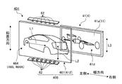
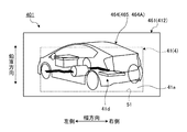
また、図15は、変形例3に係る表示装置の模式的な分解斜視図であり、図16は、変形例3に係る表示装置の奥行き方向前面側の正面図である。図15、図16は、変形例に係る表示装置401のうち主に背面側表示装置4のディスプレイ41、及び、前面側表示装置406に係る構成を取り出しこれらを模式的に図示している。図15、図16に示す変形例に係る表示装置401は、前面側表示装置6にかえて前面側表示装置406を備え、背面側表示装置4と前面側表示装置406とが奥行き方向に重なって設けられることで、ツーレイヤー式表示装置を構成する。   FIG. 15 is a schematic exploded perspective view of a display device according to Modification 3. FIG. 16 is a front view of the display device according to Modification 3 on the front side in the depth direction. FIG. 15 and FIG. 16 schematically show the configurations related to the display 41 of the back side display device 4 and the front side display device 406 out of the display device 401 according to the modification. A display device 401 according to the modification shown in FIGS. 15 and 16 includes a front side display device 406 instead of the front side display device 6, and the rear side display device 4 and the front side display device 406 overlap in the depth direction. By being provided, a two-layer display device is configured.

また、本変形例の前面側表示装置406は、透明文字板61にかえて透明文字板461を備える。透明文字板461は、上述の透明文字板61と同様に、背面側表示装置4の前面側、さらに言えば、文字板5の前面側に重ねて設けられる。透明文字板461は、上述の透明文字板61と同様に、ディスプレイ41から照射された光を透過する透過性を有する透明部材(透明媒体)によって形成される透明導光板である。ただし、以上で説明した透明導光板61は、メイン透明文字板61Aと、一対のサブ透明文字板61B、61Cの3つを含んで構成されるものとして説明したが、透明文字板461は、少なくともディスプレイ41の画像表示面41aの前面側に重ねて設けられる1つの透明文字板によって構成される。ここでは、透明文字板461は、背面側表示装置4の前面側、さらに言えば、文字板5の前面側の全体を覆っている。透明文字板461は、透明文字板61と同様に、図柄(表示意匠)464を構成する凹凸部としての複数の微細な溝465が形成される。図柄464を構成する溝465は、溝65と同様に、透明文字板461の主面上、ここでは、当該透明文字板461の背面側の主面上に形成される。また、複数の微細な溝465は、溝65と同様に、幅方向に沿って形成される。すなわち、溝465の延在方向L1は、幅方向に沿った方向である。また、溝465の延在方向L1は、光源62による光の照射方向(言い換えれば光軸方向)L2、及び、ディスプレイ41が照射する光の偏光方向L3と直交する。これにより、図柄464は、上述の図柄64と同様に、表示構造66(図6参照)、及び、非表示構造67(図6参照)が構成される。ここでは、透明文字板461は、図柄464として、微細な溝465によって、「車の形状を模したアイコン」の実像図柄464Aが描かれている。そして、本変形例に係る表示装置401において、第2層目の表示面である第2表示面412は、図柄464を構成する溝465が形成された透明文字板461の奥行き方向背面側の主面によって構成される。ここでは、第1表示面11と第2表示面412とは、上記と同様に、奥行き方向に沿って間隔をあけて対向して設けられることで、第1表示面11と第2表示面412とが間をあけて重ねて設けられる。   Further, the front side display device 406 of this modification includes a transparent dial plate 461 in place of the transparent dial plate 61. Similar to the transparent dial 61 described above, the transparent dial 461 is provided so as to overlap the front side of the rear display device 4, more specifically, the front side of the dial 5. The transparent dial plate 461 is a transparent light guide plate formed by a transparent member (transparent medium) having transparency that transmits the light irradiated from the display 41, like the transparent dial plate 61 described above. However, the transparent light guide plate 61 described above is described as including the main transparent dial plate 61A and the pair of sub transparent dial plates 61B and 61C. However, the transparent dial plate 461 includes at least The display 41 is configured by a single transparent dial plate provided on the front side of the image display surface 41a of the display 41. Here, the transparent dial plate 461 covers the entire front side of the back side display device 4, that is, the front side of the dial plate 5. Similar to the transparent dial plate 61, the transparent dial plate 461 is formed with a plurality of fine grooves 465 as concave and convex portions constituting the design (display design) 464. Like the groove 65, the groove 465 constituting the pattern 464 is formed on the main surface of the transparent dial plate 461, here, on the main surface on the back side of the transparent dial plate 461. Further, the plurality of fine grooves 465 are formed along the width direction in the same manner as the grooves 65. That is, the extending direction L1 of the groove 465 is a direction along the width direction. The extending direction L1 of the groove 465 is orthogonal to the light irradiation direction (in other words, the optical axis direction) L2 of the light source 62 and the polarization direction L3 of the light irradiated from the display 41. Thereby, the design 464 includes the display structure 66 (see FIG. 6) and the non-display structure 67 (see FIG. 6), similarly to the design 64 described above. Here, on the transparent dial 461, a real image symbol 464A of an “icon imitating the shape of a car” is drawn as a symbol 464 by a fine groove 465. In the display device 401 according to this modification, the second display surface 412 that is the display surface of the second layer is the main surface on the back side in the depth direction of the transparent dial 461 in which the grooves 465 forming the symbol 464 are formed. Consists of faces. Here, similarly to the above, the first display surface 11 and the second display surface 412 are provided to face each other with a gap along the depth direction, as described above. And are provided overlapping each other.

そして、表示装置401は、少なくとも図柄464の一部が第1表示面11と第2表示面412との積層方向に沿って視て第1表示面11の表示領域内と表示領域外とにまたがって描かれる。つまり、図柄464は、第1表示面11における表示領域と非表示領域との境界にまたがって重なるようにして描かれる。ここでは、表示装置401は、図柄464である「車の形状を模したアイコン」の実像図柄464Aが第1表示面11を構成する画像表示面41aの前面側に描かれ、画像表示面41aの略矩形状の表示領域内と表示領域外とにまたがって描かれる。またここでは、第1表示面11と第2表示面412とは、車両情報と図柄464とを連携させた少なくとも1つの情報を表示する。表示装置401は、例えば、ディスプレイ41の画像表示面41a(第1表示面11)に表示される車両情報に関する画像、ここでは、図柄464によって模式的に表された車が搭載する駆動系を模したアイコン画像41dと、透明文字板461(第2表示面412)に描かれ点灯表示された車の形状を模したアイコンの実像図柄464Aとが組み合わされて連携し、当該車が搭載する駆動系の状態に関する車両情報を表示する。この場合であっても、表示装置401は、表示装置1と同様に、第1表示面11の車両情報と第2表示面412の図柄464とで全体として表示領域を相対的に大きく見せる視覚効果を得ることができ、例えば、車が搭載する駆動系の状態をわかり易く報知することができる。なお、アイコン画像41dは、静止した画像に限られず、アニメーション等の動画像も含まれる。   In the display device 401, at least a part of the design 464 is viewed along the stacking direction of the first display surface 11 and the second display surface 412 and spans the display area of the first display surface 11 and the outside of the display area. Drawn. That is, the pattern 464 is drawn so as to overlap the boundary between the display area and the non-display area on the first display surface 11. Here, in the display device 401, the real image symbol 464A of the “icon imitating the shape of a car” as the symbol 464 is drawn on the front side of the image display surface 41a constituting the first display surface 11, and the image display surface 41a It is drawn across a substantially rectangular display area and outside the display area. Further, here, the first display surface 11 and the second display surface 412 display at least one information in which the vehicle information and the symbol 464 are linked. The display device 401 is, for example, an image relating to vehicle information displayed on the image display surface 41a (first display surface 11) of the display 41, here, a drive system mounted on a vehicle schematically represented by a symbol 464. The icon image 41d and the real image pattern 464A of the icon imitating the shape of the car drawn and lit on the transparent dial 461 (second display surface 412) are combined and linked together, and the drive system mounted on the car Displays vehicle information regarding the state of the vehicle. Even in this case, similarly to the display device 1, the display device 401 has a visual effect that makes the display area relatively large as a whole by the vehicle information on the first display surface 11 and the symbol 464 on the second display surface 412. For example, the state of the drive system mounted on the vehicle can be notified in an easy-to-understand manner. Note that the icon image 41d is not limited to a still image, and includes a moving image such as an animation.

また、以上の説明では、第1表示面11と第2表示面12は、車両情報と図柄64とを連携させた少なくとも1つの情報を表示するものとして説明したがこれに限らず、図柄64が第1表示面11の表示領域内と表示領域外とにまたがって描かれていればよい。   In the above description, the first display surface 11 and the second display surface 12 have been described as displaying at least one piece of information in which the vehicle information and the symbol 64 are linked. It is only necessary to be drawn across the display area of the first display surface 11 and the outside of the display area.

以上で説明した図9では、溝65を、底部の角度をほぼ90°(deg)とした直角二等辺三角形をなす略V字状の断面形状であるものとして説明したがこれに限らない。溝65は、例えば、底部の角度が90°(deg)でなくてもよく、また、二等辺三角形でない略V字状の断面形状であってもよい。また、以上の説明では、第2表示面12に形成された図柄64は、凹凸部としての複数の微細な溝65によって構成されるものとして説明したがこれに限らず、光源62からの光を反射させる凹凸部としては、複数の微細なドット、複数の微細な凹凸を有する印刷層等の光反射構造であってもよい。   In FIG. 9 described above, the groove 65 has been described as having a substantially V-shaped cross-sectional shape forming a right isosceles triangle with a bottom angle of approximately 90 ° (deg), but is not limited thereto. For example, the groove 65 may not have a bottom angle of 90 ° (deg), and may have a substantially V-shaped cross-sectional shape that is not an isosceles triangle. Further, in the above description, the pattern 64 formed on the second display surface 12 has been described as being constituted by a plurality of fine grooves 65 as the concavo-convex portions, but the present invention is not limited thereto, and the light from the light source 62 is used. As the concavo-convex portion to be reflected, a light reflecting structure such as a printing layer having a plurality of fine dots or a plurality of fine concavo-convex portions may be used.

1、201、301、401 表示装置
4、304 背面側表示装置
6、306、406 前面側表示装置
11、311 第1表示面
12、312、412 第2表示面
41、341 ディスプレイ
41a、341a 画像表示面
41b 指針画像(画像)
41c 速度計小目盛画像(画像)
41d アイコン画像
42、242 セグメント表示部
52 セグメントバー
61、361、461 透明文字板
62 光源
64、364、464 図柄
64A 速度計大目盛図柄(図柄、指標部)
64a 円弧状の部分
65、365、465 溝(凹凸部)
364A、464A 実像図柄
L1 延在方向
L2 照射方向
L3 偏光方向
1, 201, 301, 401 Display device 4, 304 Rear side display device 6, 306, 406 Front side display device 11, 311 First display surface 12, 312, 412 Second display surface 41, 341 Display 41a, 341a Image display Surface 41b Pointer image (image)
41c Speedometer small scale image (image)
41d Icon image 42, 242 Segment display part 52 Segment bar 61, 361, 461 Transparent dial 62 Light source 64, 364, 464 Design 64A Speedometer large scale design (design, index part)
64a Arc-shaped portions 65, 365, 465 grooves (uneven portions)
364A, 464A Real image pattern L1 Extension direction L2 Irradiation direction L3 Polarization direction

Claims (6)

車両情報を表示する第1表示面と、
前記第1表示面に重ねて設けられ光を透過すると共に、前記第1表示面との積層方向に沿って視て前記第1表示面の表示領域内と表示領域外とにまたがって描かれた図柄を有し、当該図柄を表示する表示状態と、当該図柄を非表示とする非表示状態とに切り替え可能である第2表示面とを備え、
前記第1表示面と前記第2表示面とによって情報を表示することを特徴とする、
表示装置。
A first display surface for displaying vehicle information;
Overlaid on the first display surface, transmits light, and is drawn across the display area and outside the display area of the first display surface as viewed along the stacking direction with the first display surface. A second display surface having a design and capable of switching between a display state for displaying the design and a non-display state for not displaying the design;
Information is displayed on the first display surface and the second display surface,
Display device.
前記第1表示面と前記第2表示面とは、前記車両情報と前記図柄とを連携させた少なくとも1つの情報を表示する、
請求項1に記載の表示装置。
The first display surface and the second display surface display at least one information in which the vehicle information and the symbol are linked,
The display device according to claim 1.
前記第1表示面は、矩形状の表示領域を含み、
前記図柄は、前記第1表示面の矩形状の表示領域内から表示領域外に張り出した円弧状の部分を含む、
請求項1又は請求項2に記載の表示装置。
The first display surface includes a rectangular display area,
The design includes an arc-shaped portion that protrudes from the rectangular display area of the first display surface to the outside of the display area.
The display device according to claim 1.
前記第1表示面は、前記車両情報として指針の画像を表示し、
前記図柄は、前記指針の画像の周りに設けられ当該指針の画像によって指し示される指標部を含んで構成される、
請求項1乃至請求項3のいずれか1項に記載の表示装置。
The first display surface displays an image of a pointer as the vehicle information,
The symbol is configured to include an indicator portion provided around the pointer image and pointed to by the pointer image.
The display device according to claim 1.
前記第2表示面は、前記図柄を構成する凹凸部が形成され、光源から照射される光によって前記図柄を表示する前記表示状態と、前記光源が消灯することで前記図柄を非表示とする前記非表示状態とを切り替え可能である、
請求項1乃至請求項4のいずれか1項に記載の表示装置。
The second display surface is formed with a concavo-convex portion constituting the symbol, the display state in which the symbol is displayed by light irradiated from a light source, and the symbol is not displayed by turning off the light source. It can be switched between non-display state,
The display device according to any one of claims 1 to 4.
前記第1表示面は、一方向に偏光された光によって前記車両情報に関する画像を表示し、
前記凹凸部は、前記第2表示面に形成され前記偏向された光の偏光方向と交差する方向に延在する溝である、
請求項5に記載の表示装置。
The first display surface displays an image related to the vehicle information by light polarized in one direction,
The concavo-convex portion is a groove formed on the second display surface and extending in a direction crossing a polarization direction of the deflected light.
The display device according to claim 5.
JP2015246365A 2014-12-24 2015-12-17 Display device Active JP6646431B2 (en)

Applications Claiming Priority (2)

Application Number Priority Date Filing Date Title
JP2014260373 2014-12-24

Publications (2)

Publication Number Publication Date
JP2016122002A true JP2016122002A (en) 2016-07-07
JP6646431B2 JP6646431B2 (en) 2020-02-14

Family

ID=56116848

Family Applications (1)

Application Number Title Priority Date Filing Date
JP2015246365A Active JP6646431B2 (en) 2014-12-24 2015-12-17 Display device

Country Status (3)

Country Link
US (1) US10192522B2 (en)
JP (1) JP6646431B2 (en)
DE (1) DE102015226570B4 (en)

Cited By (11)

* Cited by examiner, † Cited by third party
Publication number Priority date Publication date Assignee Title
WO2018088024A1 (en) * 2016-11-08 2018-05-17 株式会社デンソー Vehicular display device
JP2018075931A (en) * 2016-11-08 2018-05-17 株式会社デンソー Vehicular display device
JP2018081075A (en) * 2016-11-08 2018-05-24 株式会社デンソー Vehicle display device
JP2018091762A (en) * 2016-12-05 2018-06-14 株式会社デンソー Display device for vehicles
JP2018205291A (en) * 2017-06-05 2018-12-27 株式会社デンソー Display device for vehicle
US10259385B2 (en) 2017-05-25 2019-04-16 Denso Corporation Vehicular display device
KR20190047051A (en) * 2016-11-08 2019-05-07 가부시키가이샤 덴소 Vehicle display device
KR20200023665A (en) * 2018-08-14 2020-03-06 현대자동차주식회사 Cluster structure of vehicle
JP2020083177A (en) * 2018-11-29 2020-06-04 ダイハツ工業株式会社 Vehicular meter unit
JP2021012059A (en) * 2019-07-04 2021-02-04 株式会社デンソー Display device
US11073650B2 (en) 2016-11-08 2021-07-27 Denso Corporation Display device for vehicles

Families Citing this family (14)

* Cited by examiner, † Cited by third party
Publication number Priority date Publication date Assignee Title
JP6201810B2 (en) * 2014-02-26 2017-09-27 日本精機株式会社 Vehicle display device
JP6252501B2 (en) * 2015-01-20 2017-12-27 マツダ株式会社 Vehicle display device
JP6202013B2 (en) * 2015-02-05 2017-09-27 マツダ株式会社 Vehicle display device
JP6673288B2 (en) * 2017-04-27 2020-03-25 株式会社デンソー Display device for vehicles
US20190171064A1 (en) * 2017-11-22 2019-06-06 Pure Depth, Inc. Soft additive image modality for multi-layer display
EP3598259B1 (en) * 2018-07-19 2021-09-01 Panasonic Intellectual Property Management Co., Ltd. Information processing method and information processing system
CN114126922B (en) 2018-11-23 2024-01-05 上海延锋金桥汽车饰件系统有限公司 Vehicle interior component
DE102019207322B4 (en) * 2019-05-20 2021-07-29 Siemens Aktiengesellschaft Optical reading device for a pointer instrument
US11915570B2 (en) * 2020-07-16 2024-02-27 Ventec Life Systems, Inc. System and method for concentrating gas
US11931689B2 (en) 2020-07-16 2024-03-19 Ventec Life Systems, Inc. System and method for concentrating gas
CN114882791A (en) * 2021-02-05 2022-08-09 群创光电股份有限公司 Transparent display device
CN113752832B (en) * 2021-09-13 2022-03-29 黑龙江天有为电子有限责任公司 Automobile instrument panel
CN113895228B (en) * 2021-10-11 2022-05-17 黑龙江天有为电子有限责任公司 Automobile combination instrument panel and automobile
USD1013784S1 (en) * 2021-12-23 2024-02-06 Dory As Digital sign

Family Cites Families (10)

* Cited by examiner, † Cited by third party
Publication number Priority date Publication date Assignee Title
JP4258896B2 (en) * 1999-07-14 2009-04-30 株式会社デンソー Compound display device
JP3804499B2 (en) * 2001-09-25 2006-08-02 株式会社デンソー Combination meter for automobile
JP2003227884A (en) * 2001-11-29 2003-08-15 Casio Comput Co Ltd Light emission and display device and electronic apparatus
JP4568087B2 (en) 2004-01-28 2010-10-27 矢崎総業株式会社 Vehicle display device
EP1666933A1 (en) * 2004-12-02 2006-06-07 Asulab S.A. Dual illumination function optical device and figurative image formation
JP2006201038A (en) * 2005-01-20 2006-08-03 Denso Corp Display device
JP5034961B2 (en) * 2008-01-11 2012-09-26 株式会社デンソー Pointer instrument
JP5239925B2 (en) 2009-02-16 2013-07-17 日本精機株式会社 Display board and instrument device using this display board
JP5413744B2 (en) 2010-07-30 2014-02-12 株式会社デンソー Display device
TWI442110B (en) * 2011-01-26 2014-06-21 Coretronic Corp Light guide plate and light source module

Cited By (16)

* Cited by examiner, † Cited by third party
Publication number Priority date Publication date Assignee Title
KR102277852B1 (en) * 2016-11-08 2021-07-16 가부시키가이샤 덴소 vehicle display device
JP2018075931A (en) * 2016-11-08 2018-05-17 株式会社デンソー Vehicular display device
JP2018081075A (en) * 2016-11-08 2018-05-24 株式会社デンソー Vehicle display device
WO2018088024A1 (en) * 2016-11-08 2018-05-17 株式会社デンソー Vehicular display device
KR20190047051A (en) * 2016-11-08 2019-05-07 가부시키가이샤 덴소 Vehicle display device
JP2019207259A (en) * 2016-11-08 2019-12-05 株式会社デンソー Vehicle display device
US11117468B2 (en) 2016-11-08 2021-09-14 Denso Corporation Display device for vehicle
US11073650B2 (en) 2016-11-08 2021-07-27 Denso Corporation Display device for vehicles
JP2018091762A (en) * 2016-12-05 2018-06-14 株式会社デンソー Display device for vehicles
US10259385B2 (en) 2017-05-25 2019-04-16 Denso Corporation Vehicular display device
JP2018205291A (en) * 2017-06-05 2018-12-27 株式会社デンソー Display device for vehicle
KR20200023665A (en) * 2018-08-14 2020-03-06 현대자동차주식회사 Cluster structure of vehicle
KR102552497B1 (en) 2018-08-14 2023-07-06 현대자동차주식회사 Cluster structure of vehicle
JP2020083177A (en) * 2018-11-29 2020-06-04 ダイハツ工業株式会社 Vehicular meter unit
JP7069454B2 (en) 2018-11-29 2022-05-18 ダイハツ工業株式会社 Vehicle meter unit
JP2021012059A (en) * 2019-07-04 2021-02-04 株式会社デンソー Display device

Also Published As

Publication number Publication date
DE102015226570B4 (en) 2021-12-23
US20160189345A1 (en) 2016-06-30
US10192522B2 (en) 2019-01-29
JP6646431B2 (en) 2020-02-14
DE102015226570A1 (en) 2016-06-30

Similar Documents

Publication Publication Date Title
JP6646431B2 (en) Display device
JP6469666B2 (en) Display device
JP6232013B2 (en) Display device
CN106687772B (en) Display device
JP6510229B2 (en) Display device
JP6585430B2 (en) Display device
JP6412795B2 (en) Display device
US20160207456A1 (en) Vehicle display device
JP2018045098A (en) Aerial display device
JP2005257333A (en) Display device for vehicle
JP2012108470A (en) Head-up display device
JP6539512B2 (en) Display device
US20180001768A1 (en) Head-up display apparatus
JP6365313B2 (en) Display device
JP6522351B2 (en) Display device
JP6615156B2 (en) Vehicle display device
WO2017002289A1 (en) Display device
JP6390324B2 (en) Display device
JP6854197B2 (en) Vehicle display device and design board
JP6384159B2 (en) Display device
JP2022113435A (en) Instrumental device
JP2021012059A (en) Display device
JP2015025715A (en) Display device for vehicle
JP2013096719A (en) Parallactic display board and instrument device having parallactic display board
JP2020003321A (en) Display device

Legal Events

Date Code Title Description
A621 Written request for application examination

Free format text: JAPANESE INTERMEDIATE CODE: A621

Effective date: 20181119

A977 Report on retrieval

Free format text: JAPANESE INTERMEDIATE CODE: A971007

Effective date: 20191015

A131 Notification of reasons for refusal

Free format text: JAPANESE INTERMEDIATE CODE: A131

Effective date: 20191023

A521 Request for written amendment filed

Free format text: JAPANESE INTERMEDIATE CODE: A523

Effective date: 20191121

TRDD Decision of grant or rejection written
A01 Written decision to grant a patent or to grant a registration (utility model)

Free format text: JAPANESE INTERMEDIATE CODE: A01

Effective date: 20200107

A61 First payment of annual fees (during grant procedure)

Free format text: JAPANESE INTERMEDIATE CODE: A61

Effective date: 20200110

R150 Certificate of patent or registration of utility model

Ref document number: 6646431

Country of ref document: JP

Free format text: JAPANESE INTERMEDIATE CODE: R150

R250 Receipt of annual fees

Free format text: JAPANESE INTERMEDIATE CODE: R250

S531 Written request for registration of change of domicile

Free format text: JAPANESE INTERMEDIATE CODE: R313531

R350 Written notification of registration of transfer

Free format text: JAPANESE INTERMEDIATE CODE: R350

R250 Receipt of annual fees

Free format text: JAPANESE INTERMEDIATE CODE: R250