JP6232013B2 - Display device - Google Patents

Display device Download PDF

Info

Publication number
JP6232013B2
JP6232013B2 JP2015111245A JP2015111245A JP6232013B2 JP 6232013 B2 JP6232013 B2 JP 6232013B2 JP 2015111245 A JP2015111245 A JP 2015111245A JP 2015111245 A JP2015111245 A JP 2015111245A JP 6232013 B2 JP6232013 B2 JP 6232013B2
Authority
JP
Japan
Prior art keywords
display
light
display surface
groove
display device
Prior art date
Legal status (The legal status is an assumption and is not a legal conclusion. Google has not performed a legal analysis and makes no representation as to the accuracy of the status listed.)
Active
Application number
JP2015111245A
Other languages
Japanese (ja)
Other versions
JP2016223936A (en
Inventor
順雄 藤田
順雄 藤田
Current Assignee (The listed assignees may be inaccurate. Google has not performed a legal analysis and makes no representation or warranty as to the accuracy of the list.)
Yazaki Corp
Original Assignee
Yazaki Corp
Priority date (The priority date is an assumption and is not a legal conclusion. Google has not performed a legal analysis and makes no representation as to the accuracy of the date listed.)
Filing date
Publication date
Application filed by Yazaki Corp filed Critical Yazaki Corp
Priority to JP2015111245A priority Critical patent/JP6232013B2/en
Priority to US15/163,283 priority patent/US9983347B2/en
Priority to DE102016209086.0A priority patent/DE102016209086B4/en
Publication of JP2016223936A publication Critical patent/JP2016223936A/en
Application granted granted Critical
Publication of JP6232013B2 publication Critical patent/JP6232013B2/en
Active legal-status Critical Current
Anticipated expiration legal-status Critical

Links

Images

Classifications

    • GPHYSICS
    • G02OPTICS
    • G02BOPTICAL ELEMENTS, SYSTEMS OR APPARATUS
    • G02B6/00Light guides; Structural details of arrangements comprising light guides and other optical elements, e.g. couplings
    • G02B6/0001Light guides; Structural details of arrangements comprising light guides and other optical elements, e.g. couplings specially adapted for lighting devices or systems
    • G02B6/0011Light guides; Structural details of arrangements comprising light guides and other optical elements, e.g. couplings specially adapted for lighting devices or systems the light guides being planar or of plate-like form
    • G02B6/0033Means for improving the coupling-out of light from the light guide
    • G02B6/0058Means for improving the coupling-out of light from the light guide varying in density, size, shape or depth along the light guide
    • G02B6/006Means for improving the coupling-out of light from the light guide varying in density, size, shape or depth along the light guide to produce indicia, symbols, texts or the like
    • BPERFORMING OPERATIONS; TRANSPORTING
    • B60VEHICLES IN GENERAL
    • B60QARRANGEMENT OF SIGNALLING OR LIGHTING DEVICES, THE MOUNTING OR SUPPORTING THEREOF OR CIRCUITS THEREFOR, FOR VEHICLES IN GENERAL
    • B60Q1/00Arrangement of optical signalling or lighting devices, the mounting or supporting thereof or circuits therefor
    • B60Q1/26Arrangement of optical signalling or lighting devices, the mounting or supporting thereof or circuits therefor the devices being primarily intended to indicate the vehicle, or parts thereof, or to give signals, to other traffic
    • GPHYSICS
    • G02OPTICS
    • G02BOPTICAL ELEMENTS, SYSTEMS OR APPARATUS
    • G02B6/00Light guides; Structural details of arrangements comprising light guides and other optical elements, e.g. couplings
    • G02B6/0001Light guides; Structural details of arrangements comprising light guides and other optical elements, e.g. couplings specially adapted for lighting devices or systems
    • G02B6/0011Light guides; Structural details of arrangements comprising light guides and other optical elements, e.g. couplings specially adapted for lighting devices or systems the light guides being planar or of plate-like form
    • G02B6/0033Means for improving the coupling-out of light from the light guide
    • G02B6/0035Means for improving the coupling-out of light from the light guide provided on the surface of the light guide or in the bulk of it
    • G02B6/00362-D arrangement of prisms, protrusions, indentations or roughened surfaces

Description

本発明は、表示装置に関する。   The present invention relates to a display device.

車両等に搭載される従来の表示装置として、例えば、特許文献1には、車両の計器を表示する第1表示部と、付加的情報を表示する第2表示部とを備える表示装置が開示されている。当該表示装置の第2表示部は、第1表示部の目盛盤の表側に重ねて複数枚の無色透明の導光板が配置され、当該導光板に溝によって図柄が形成されている。   As a conventional display device mounted on a vehicle or the like, for example, Patent Document 1 discloses a display device including a first display unit that displays a vehicle instrument and a second display unit that displays additional information. ing. In the second display unit of the display device, a plurality of colorless and transparent light guide plates are arranged on the front side of the scale plate of the first display unit, and a pattern is formed on the light guide plate by a groove.

特開2012−32286号公報JP 2012-32286 A

ところで、このような表示装置は、例えば、より多様な表示を実現するべく、上述の特許文献1に記載の第1表示部にかえて、液晶ディスプレイ等によって当該第1表示部で行っている表示と同様の表示を行う場合がある。このような場合に、表示装置は、液晶ディスプレイ等からの光が導光板上で図柄を構成する溝にて回折することで、当該液晶ディスプレイで表示されている画像の虚像が発生するおそれがあり、これにより、視認性が悪化するおそれがある。   By the way, in such a display device, for example, a display performed on the first display unit by a liquid crystal display or the like instead of the first display unit described in Patent Document 1 in order to realize more various displays. May be displayed in the same way. In such a case, the display device may generate a virtual image of the image displayed on the liquid crystal display because the light from the liquid crystal display or the like is diffracted on the light guide plate in the grooves constituting the design. As a result, the visibility may deteriorate.

本発明は、上記の事情に鑑みてなされたものであって、適正な視認性を確保することができる表示装置を提供することを目的とする。   The present invention has been made in view of the above circumstances, and an object thereof is to provide a display device capable of ensuring appropriate visibility.

上記目的を達成するために、本発明に係る表示装置は、光を出射し車両情報を表示する第1表示面と、前記第1表示面に重ねて設けられ前記第1表示面から出射された光を透過すると共に図柄を構成する溝が形成された第2表示面とを備え、前記溝は、前記第1表示面から出射され当該溝で回折した可視光域成分の回折光が車両に応じて予め定まるアイレンジ内で結像しない溝ピッチで複数形成されることを特徴とする。   In order to achieve the above object, a display device according to the present invention is provided with a first display surface that emits light and displays vehicle information, and is superimposed on the first display surface and emitted from the first display surface. A second display surface that transmits light and has a groove that forms a pattern, and the groove emits diffracted light of a visible light region component that is emitted from the first display surface and diffracted by the groove according to the vehicle. And a plurality of groove pitches that do not form an image within a predetermined eye range.

上記目的を達成するために、本発明に係る表示装置は、光を出射し車両情報に関する画像を表示する第1表示面と、前記第1表示面に重ねて設けられ前記第1表示面から出射された光を透過すると共に図柄を構成する溝が形成された第2表示面とを備え、前記第1表示面と前記第2表示面への光の入射面と前記第2表示面からの光の出射面とは、互いに平行であり、前記溝は、水平方向に延在し、溝ピッチが0より大きく0.5μm以下とされることで、前記第1表示面と当該第1表示面の法線との交点を基準として、鉛直方向に当該第1表示面の法線を中心とした20度の角度範囲内に、前記第1表示面から出射され当該溝で回折した可視光域成分の回折光を結像させないことを特徴とする。   In order to achieve the above object, a display device according to the present invention is provided with a first display surface that emits light and displays an image relating to vehicle information, and overlaps with the first display surface and is emitted from the first display surface. And a second display surface on which grooves constituting the design are formed, and the first display surface, the light incident surface on the second display surface, and the light from the second display surface Are parallel to each other, the grooves extend in the horizontal direction, and the groove pitch is set to be greater than 0 and 0.5 μm or less, so that the first display surface and the first display surface are With reference to the intersection with the normal line, the visible light region component emitted from the first display surface and diffracted by the groove within an angle range of 20 degrees centered on the normal line of the first display surface in the vertical direction. The diffracted light is not imaged.

また、上記表示装置では、前記溝ピッチは、前記第1表示面から出射され前記溝で回折した可視光域成分の回折光が予め設定される所定の領域内で結像しない範囲で最大とされるものとすることができる。   In the display device, the groove pitch is maximized in a range where the diffracted light of the visible light region component emitted from the first display surface and diffracted by the groove does not form an image within a predetermined region set in advance. Can be.

また、上記表示装置では、前記第1表示面は、一方向に偏光された光によって前記車両情報を表示し、前記溝は、前記偏向された光の偏光方向と交差する方向に延在するものとすることができる。   In the display device, the first display surface displays the vehicle information by light polarized in one direction, and the groove extends in a direction intersecting with the polarization direction of the deflected light. It can be.

本発明に係る表示装置は、第1表示面に表示される車両情報に関する画像と、第1表示面に重ねて設けられ第1表示面から出射された光を透過する第2表示面に形成された図柄とを組み合わせた表示を行うことができる。この場合、表示装置は、第2表示面の図柄を構成する溝が所定の溝ピッチで複数形成されるので、第1表示面から出射され当該溝で回折した可視光域成分の回折光が車両に応じて予め定まるアイレンジ内で結像しないようにすることができる。この結果、表示装置は、アイレンジ内の目視位置にて、当該第1表示面で表示されている画像の虚像が視認されることを抑制することができるので、適正な視認性を確保することができる、という効果を奏する。   The display device according to the present invention is formed on an image relating to vehicle information displayed on the first display surface and a second display surface that is provided so as to overlap the first display surface and transmits light emitted from the first display surface. Can be displayed in combination with other symbols. In this case, since the display device has a plurality of grooves constituting the design of the second display surface at a predetermined groove pitch, the diffracted light of the visible light region component emitted from the first display surface and diffracted by the grooves is the vehicle. Accordingly, it is possible to prevent image formation within an eye range determined in advance. As a result, the display device can prevent the virtual image of the image displayed on the first display surface from being visually recognized at the viewing position in the eye range, and thus ensure appropriate visibility. There is an effect that can be.

図1は、実施形態に係る表示装置の概略構成を示す分解斜視図である。FIG. 1 is an exploded perspective view illustrating a schematic configuration of a display device according to an embodiment. 図2は、実施形態に係る表示装置の重畳表示装置の概略構成を示す模式的な斜視図である。FIG. 2 is a schematic perspective view illustrating a schematic configuration of the superimposed display device of the display device according to the embodiment. 図3は、図2中のA−Aの模式的な断面図である。3 is a schematic cross-sectional view taken along line AA in FIG. 図4は、図3中の囲み線B内の部分的な断面図である。FIG. 4 is a partial cross-sectional view taken along a surrounding line B in FIG. 図5は、表示装置の輝度実測試験の前提条件について説明する模式図である。FIG. 5 is a schematic diagram for explaining the preconditions for the luminance measurement test of the display device. 図6は、表示装置の輝度実測試験の前提条件について説明する模式図である。FIG. 6 is a schematic diagram for explaining the preconditions for the luminance measurement test of the display device. 図7は、表示装置の輝度実測試験の前提条件について説明する模式図である。FIG. 7 is a schematic diagram for explaining the preconditions for the luminance measurement test of the display device. 図8は、表示装置の輝度実測試験の結果を表す線図である。FIG. 8 is a diagram showing the result of the brightness measurement test of the display device. 図9は、比較例に係る表示装置において虚像が発生する原理について説明する模式図である。FIG. 9 is a schematic diagram illustrating the principle of generating a virtual image in the display device according to the comparative example. 図10は、実施形態に係る表示装置における溝ピッチについて説明する模式図である。FIG. 10 is a schematic diagram illustrating the groove pitch in the display device according to the embodiment. 図11は、実施形態に係る表示装置においてアイレンジ内の目視位置にて虚像が抑制される原理について説明するための模式図である。FIG. 11 is a schematic diagram for explaining the principle that the virtual image is suppressed at the viewing position in the eye range in the display device according to the embodiment. 図12は、実施形態に係る表示装置のディスプレイの輝度分布を表す線図である。FIG. 12 is a diagram showing the luminance distribution of the display of the display device according to the embodiment. 図13は、溝ピッチが1μmである場合のアイレンジER内での結像の有無を評価するための線図である。FIG. 13 is a diagram for evaluating the presence / absence of image formation in the eye range ER when the groove pitch is 1 μm. 図14は、溝ピッチが0.5μmである場合のアイレンジER内での結像の有無を評価するための線図である。FIG. 14 is a diagram for evaluating the presence or absence of imaging within the eye range ER when the groove pitch is 0.5 μm. 図15は、溝ピッチが0.4μmである場合のアイレンジER内での結像の有無を評価するための線図である。FIG. 15 is a diagram for evaluating the presence / absence of image formation in the eye range ER when the groove pitch is 0.4 μm. 図16は、変形例に係る表示装置の概略構成を表す模式的な分解斜視図である。FIG. 16 is a schematic exploded perspective view illustrating a schematic configuration of a display device according to a modification.

以下に、本発明に係る実施形態を図面に基づいて詳細に説明する。なお、この実施形態によりこの発明が限定されるものではない。また、下記実施形態における構成要素には、当業者が置換可能かつ容易なもの、あるいは実質的に同一のものが含まれる。   Embodiments according to the present invention will be described below in detail with reference to the drawings. In addition, this invention is not limited by this embodiment. In addition, constituent elements in the following embodiments include those that can be easily replaced by those skilled in the art or those that are substantially the same.

[実施形態]
図1は、実施形態に係る表示装置の概略構成を示す分解斜視図である。図2は、実施形態に係る表示装置の重畳表示装置の概略構成を示す模式的な斜視図である。図3は、図2中のA−Aの模式的な断面図である。図4は、図3中の囲み線B内の部分的な断面図である。図5、図6、図7は、表示装置の輝度実測試験の前提条件について説明する模式図である。図8は、表示装置の輝度実測試験の結果を表す線図である。図9は、比較例に係る表示装置において虚像が発生する原理について説明する模式図である。図10は、実施形態に係る表示装置における溝ピッチについて説明する模式図である。図11は、実施形態に係る表示装置においてアイレンジ内の目視位置にて虚像が抑制される原理について説明するための模式図である。図12は、実施形態に係る表示装置のディスプレイの輝度分布を表す線図である。図13は、溝ピッチが1μmである場合のアイレンジ内での結像の有無を評価するための線図である。図14は、溝ピッチが0.5μmである場合のアイレンジ内での結像の有無を評価するための線図である。図15は、溝ピッチが0.4μmである場合のアイレンジ内での結像の有無を評価するための線図である。
[Embodiment]
FIG. 1 is an exploded perspective view illustrating a schematic configuration of a display device according to an embodiment. FIG. 2 is a schematic perspective view illustrating a schematic configuration of the superimposed display device of the display device according to the embodiment. 3 is a schematic cross-sectional view taken along line AA in FIG. FIG. 4 is a partial cross-sectional view taken along a surrounding line B in FIG. 5, FIG. 6, and FIG. 7 are schematic diagrams for explaining the preconditions for the luminance measurement test of the display device. FIG. 8 is a diagram showing the result of the brightness measurement test of the display device. FIG. 9 is a schematic diagram illustrating the principle of generating a virtual image in the display device according to the comparative example. FIG. 10 is a schematic diagram illustrating the groove pitch in the display device according to the embodiment. FIG. 11 is a schematic diagram for explaining the principle that the virtual image is suppressed at the viewing position in the eye range in the display device according to the embodiment. FIG. 12 is a diagram showing the luminance distribution of the display of the display device according to the embodiment. FIG. 13 is a diagram for evaluating the presence or absence of imaging within the eye range when the groove pitch is 1 μm. FIG. 14 is a diagram for evaluating the presence or absence of imaging within the eye range when the groove pitch is 0.5 μm. FIG. 15 is a diagram for evaluating the presence or absence of image formation within the eye range when the groove pitch is 0.4 μm.

本実施形態に係る表示装置1は、図1に示すように、いわゆるメータを構成するものであり、例えば、自動車等の車両のダッシュボードに設けられたインストルメントパネルに搭載され、車両の運転に供される種々の情報を表示する。なお、図1に示す表示装置1の幅方向とは、典型的には、この表示装置1が適用される車両の車幅方向に相当する。表示装置1の幅方向において、表示装置1の前面に向かって一方側(図1中向かって手前側)が車両の運転席側に相当し、表示装置1の前面に向かって他方側(図1中向かって奥側)が車両の助手席側に相当するがこの逆でもよい。また、図1に示す表示装置1の奥行き方向とは、典型的には、この表示装置1が適用される車両の前後方向(言い換えれば、車両進行方向)に相当する。また、表示装置1の前面側とは、車両の運転席と対面する側であり、典型的には、当該運転席に座った運転者によって視認される側である。一方、表示装置1の背面側とは、奥行き方向において前面側とは反対側であり、典型的には、インストルメントパネルの内部に収容される側である。   As shown in FIG. 1, the display device 1 according to the present embodiment constitutes a so-called meter. For example, the display device 1 is mounted on an instrument panel provided on a dashboard of a vehicle such as an automobile and is used for driving the vehicle. Displays various information provided. Note that the width direction of the display device 1 shown in FIG. 1 typically corresponds to the vehicle width direction of a vehicle to which the display device 1 is applied. In the width direction of the display device 1, one side (front side in FIG. 1) toward the front surface of the display device 1 corresponds to the driver's seat side of the vehicle, and the other side (FIG. 1) toward the front surface of the display device 1. The rear side (inward) corresponds to the passenger seat side of the vehicle, but this may be reversed. Further, the depth direction of the display device 1 shown in FIG. 1 typically corresponds to the front-rear direction of the vehicle to which the display device 1 is applied (in other words, the vehicle traveling direction). Further, the front side of the display device 1 is the side facing the driver's seat of the vehicle, and is typically the side visually recognized by the driver sitting in the driver's seat. On the other hand, the back side of the display device 1 is the side opposite to the front side in the depth direction, and is typically the side accommodated inside the instrument panel.

具体的には、表示装置1は、筐体2と、画像表示装置としてのディスプレイ3と、文字板4と、重畳表示装置5と、見返し板6とを備える。表示装置1は、奥行き方向の背面側から前面側に向かって、筐体2、ディスプレイ3、文字板4、重畳表示装置5、見返し板6の順で積層された構造となっている。   Specifically, the display device 1 includes a housing 2, a display 3 as an image display device, a dial plate 4, a superimposed display device 5, and a facing plate 6. The display device 1 has a structure in which a housing 2, a display 3, a dial 4, a superimposed display device 5, and a facing plate 6 are stacked in this order from the back side to the front side in the depth direction.

筐体2は、表示装置1を構成する種々の部品が組み付けられこれらを収容するケースを構成するものである。   The housing 2 constitutes a case in which various parts constituting the display device 1 are assembled and accommodated.

ディスプレイ3は、制御装置等を介して駆動制御され、画像表示面3aに種々の画像を表示するものである。ディスプレイ3は、例えば、薄型の液晶ディスプレイを用いることができるが、これに限らず、プラズマディスプレイ、有機ELディスプレイ等を用いることもできる。画像表示面3aに表示される画像としては、例えば、車両の速度やエコ走行等に関する情報の他、積算走行距離、冷却水温、走行用動力源の出力回転数、燃料残量、バッテリ蓄電量等、車両の運転に際して時々刻々と変化する様々な運転に関する運転情報が含まれてもよい。   The display 3 is driven and controlled via a control device or the like, and displays various images on the image display surface 3a. For example, a thin liquid crystal display can be used as the display 3, but not limited thereto, a plasma display, an organic EL display, or the like can also be used. As an image displayed on the image display surface 3a, for example, in addition to information related to the speed of the vehicle, eco-driving, etc., the accumulated travel distance, the cooling water temperature, the output rotational speed of the power source for travel, the remaining amount of fuel, the amount of battery storage In addition, driving information regarding various driving that changes every moment when driving the vehicle may be included.

文字板4は、各種の警告灯(ウォーニングランプ、いわゆるテルテール)、シフトポジションインジケータ、方向指示記号等に応じた種々の記号、文字、図形等が描かれた板状の部材である。文字板4は、背面側から光が照射され、記号、文字、図形等が描かれた部分において当該照射された光が透過されることで、当該記号、文字、図形等が点灯表示される。   The dial 4 is a plate-like member on which various warning lights (warning lamps, so-called telltales), shift position indicators, direction indication symbols, and the like are drawn. The dial 4 is irradiated with light from the back side, and the irradiated light is transmitted through the portion where the symbols, characters, graphics, etc. are drawn, so that the symbols, characters, graphics, etc. are lit and displayed.

上述のディスプレイ3は、前面側の表面が文字板4から露出しており、このディスプレイ3の前面側の表面が画像表示面3aを構成する。当該画像表示面3aは、車両情報に関する実像画像(画像)51aを表示する第1表示面51を構成する。ここで、車両情報は、表示装置1が搭載される車両の車両状態及び走行状況等、上述の様々な運転に関する運転情報を含み、第1表示面51は、これらの情報を実像画像51aとして表示することで運転者等に提示する。第1表示面51は、オン状態で実像画像51aを表示可能な状態となり、オフ状態で当該実像画像51aが非表示となる。   In the display 3 described above, the front surface is exposed from the dial 4, and the front surface of the display 3 constitutes the image display surface 3 a. The said image display surface 3a comprises the 1st display surface 51 which displays the real image image (image) 51a regarding vehicle information. Here, the vehicle information includes driving information relating to the above-described various driving operations such as the vehicle state and traveling state of the vehicle on which the display device 1 is mounted, and the first display surface 51 displays these information as a real image 51a. To the driver. The first display surface 51 is in a state in which the real image 51a can be displayed in the on state, and the real image 51a is not displayed in the off state.

重畳表示装置5は、図1、図2、図3、図4に示すように、透明導光板5aと、光源5bとを有する。透明導光板5aは、画像表示面3aの前面側に重ねて設けられる。透明導光板5aは、ディスプレイ3から照射された光を透過する透過性を有する透明部材(透明媒体)によって形成される。透明導光板5aは、図柄(表示意匠)5cを構成する微細な溝5dが形成される。図柄5cを構成する溝5dは、例えば、当該溝5dに相当する凸形状を設けた金型を用いて透明導光板5aを樹脂成形することによって、透明導光板5aの主面上、ここでは、当該透明導光板5aの背面側の主面上に凹形状となるように形成されてもよい。また、図柄5cを構成する溝5dは、例えば、レーザー加工等の種々の手法による掘り込みによって、透明導光板5aの主面上、ここでは、当該透明導光板5aの背面側の主面上に凹形状となるように形成されてもよい。透明導光板5aに溝5dによって形成される図柄5cとしては、例えば、ディスプレイ3で表示される運転情報と関連するような種々の図柄が含まれてもよい。図1の例では、図柄5cは、例えば、「車両を模した車体記号(アイコン)」であり、図2等の例では、図柄5cは、例えば、数字の「2」であるがこれらに限らない。光源5bは、透明導光板5aの端面に光を照射する。光源5bは、例えば、LED(Light Emitting Diode)素子等によって構成されるが、これに限らない。光源5bは、その光軸方向が透明導光板5aの端面と直交し、かつ、照射された光が透明導光板5aの端面から入射するように設けられている。なお、溝5dの延在方向や光源5bによる光の照射方向等については、後で詳細に説明する。   As shown in FIGS. 1, 2, 3, and 4, the superimposed display device 5 includes a transparent light guide plate 5a and a light source 5b. The transparent light guide plate 5a is provided so as to overlap the front side of the image display surface 3a. The transparent light guide plate 5a is formed by a transparent member (transparent medium) having transparency that transmits light emitted from the display 3. The transparent light guide plate 5a is formed with fine grooves 5d constituting a design (display design) 5c. The groove 5d constituting the pattern 5c is formed on the main surface of the transparent light guide plate 5a by, for example, molding the transparent light guide plate 5a using a mold having a convex shape corresponding to the groove 5d. You may form so that it may become a concave shape on the main surface by the side of the back surface of the said transparent light-guide plate 5a. Further, the grooves 5d constituting the pattern 5c are formed on the main surface of the transparent light guide plate 5a, here, on the main surface on the back side of the transparent light guide plate 5a by digging by various methods such as laser processing, for example. You may form so that it may become a concave shape. The symbols 5c formed by the grooves 5d on the transparent light guide plate 5a may include, for example, various symbols related to driving information displayed on the display 3. In the example of FIG. 1, the symbol 5c is, for example, “a vehicle symbol (icon) imitating a vehicle”. In the example of FIG. 2, the symbol 5c is, for example, the numeral “2”, but is not limited thereto. Absent. The light source 5b irradiates light to the end surface of the transparent light guide plate 5a. The light source 5b is constituted by, for example, an LED (Light Emitting Diode) element or the like, but is not limited thereto. The light source 5b is provided such that the optical axis direction thereof is orthogonal to the end surface of the transparent light guide plate 5a, and the irradiated light is incident from the end surface of the transparent light guide plate 5a. The extending direction of the groove 5d, the light irradiation direction by the light source 5b, and the like will be described in detail later.

重畳表示装置5は、光源5bが制御装置等を介して駆動制御されることで、光源5bの点灯、消灯に基づいて、図柄5cの表示、非表示が切り替えられる。重畳表示装置5は、光源5bが点灯すると図柄5cが表示された状態となり、すなわち、光源5bから照射された光が透明導光板5aの端面に入射して当該透明導光板5a内を伝播し、少なくとも当該入射光の一部の成分が図柄5cを構成する溝5dで前面側に反射し、この結果、運転者等が当該図柄5cを視認可能な状態となる(図3、図4等参照)。この場合、重畳表示装置5は、運転者が前面側(運転席側)から視たときに、透明導光板5a上に表示される図柄5cを、当該透明導光板5aの背面側に位置するディスプレイ3の画像表示面3a上の画像に重畳させて表示して所定の意匠を形成し、これにより、多様な表示を可能とすることができる。一方、重畳表示装置5は、光源5bが消灯すると図柄5cが非表示の状態となり、ディスプレイ3から照射され透明導光板5aを透過した光によって、運転者等が画像表示面3aに表示された種々の画像を視認しやすい状態となる。   In the superimposed display device 5, when the light source 5 b is driven and controlled via a control device or the like, display or non-display of the symbol 5 c is switched based on whether the light source 5 b is turned on or off. When the light source 5b is turned on, the superimposed display device 5 is in a state where the pattern 5c is displayed. That is, the light emitted from the light source 5b is incident on the end surface of the transparent light guide plate 5a and propagates through the transparent light guide plate 5a. At least a part of the component of the incident light is reflected to the front side by the groove 5d constituting the symbol 5c, and as a result, the driver or the like can visually recognize the symbol 5c (see FIGS. 3 and 4). . In this case, the superimposed display device 5 displays a pattern 5c displayed on the transparent light guide plate 5a when the driver views from the front side (driver's seat side) on the back side of the transparent light guide plate 5a. A predetermined design can be formed by superimposing on the image on the third image display surface 3a, thereby enabling various displays. On the other hand, in the superimposed display device 5, when the light source 5b is turned off, the pattern 5c is not displayed, and the driver or the like is displayed on the image display surface 3a by the light emitted from the display 3 and transmitted through the transparent light guide plate 5a. It will be in the state which is easy to visually recognize the image of.

上記のように溝5dが形成された透明導光板5aの背面側の主面は、第1表示面51に重ねて設けられ光を透過すると共に、第1表示面51が実像画像51aを表示可能であるオン状態である状態で、表示状態と非表示状態とを切り替え可能である第2表示面52を構成する。ここで、第2表示面52の表示状態とは、光源5bから照射される光によって実像図柄52aを表示する状態である。実像図柄52aとは、上述した図柄5cであり、ここでは、例えば、上述した「車両を模した車体記号(アイコン)」、すなわち、車両のシンボル等である。一方、第2表示面52の非表示状態とは、光源5bが消灯することで当該実像図柄52aを非表示とする状態である。   The main surface on the back side of the transparent light guide plate 5a in which the grooves 5d are formed as described above is provided so as to overlap the first display surface 51 and transmits light, and the first display surface 51 can display the real image 51a. The second display surface 52 that can be switched between the display state and the non-display state in the ON state is configured. Here, the display state of the second display surface 52 is a state in which the real image symbol 52a is displayed by the light emitted from the light source 5b. The real image pattern 52a is the above-described pattern 5c, and is, for example, the above-described “vehicle body symbol (icon) imitating a vehicle”, that is, a vehicle symbol or the like. On the other hand, the non-display state of the second display surface 52 is a state in which the real image pattern 52a is not displayed when the light source 5b is turned off.

上述の第1表示面51と第2表示面52とは、奥行き方向、言い換えれば、車両進行方向に、重ねられた複数の表示面を構成し、第1表示面51が当該複数の表示面の車両進行方向奥側の表示面を構成し、第2表示面52が当該複数の表示面の車両進行方向手前側(運転者等の目視者の目視位置側)の表示面を構成する。   The first display surface 51 and the second display surface 52 described above constitute a plurality of display surfaces that are overlapped in the depth direction, in other words, the vehicle traveling direction, and the first display surface 51 corresponds to the plurality of display surfaces. A display surface on the far side in the vehicle traveling direction is configured, and the second display surface 52 configures a display surface on the front side in the vehicle traveling direction of the plurality of display surfaces (the viewing position side of a viewer such as a driver).

見返し板6は、文字板4、透明導光板5a等の周囲を囲って当該文字板4、透明導光板5a等を押える枠状の部材である。   The facing plate 6 is a frame-shaped member that surrounds the dial plate 4, the transparent light guide plate 5 a, etc., and presses the dial plate 4, the transparent light guide plate 5 a, etc.

そして、本実施形態の表示装置1は、ディスプレイ3の偏光方向と図柄5c(実像図柄52a)を構成する溝5dの延在方向とが所定の角度範囲で交差するように構成することで、ディスプレイ3と重畳表示装置5とを組み合わせて多様な表示を実現した上で、適正な視認性を確保することができるようにしている。ここで、ディスプレイ3の偏光方向とは、典型的には、ディスプレイ3における最終的な透過軸方向に相当し、溝5dの延在方向とは、典型的には、当該溝5dが延びる方向に相当する。   The display device 1 of the present embodiment is configured such that the polarization direction of the display 3 and the extending direction of the groove 5d constituting the pattern 5c (real image pattern 52a) intersect within a predetermined angle range. 3 and the superimposing display device 5 are combined to realize various displays, and appropriate visibility can be ensured. Here, the polarization direction of the display 3 typically corresponds to the final transmission axis direction in the display 3, and the extending direction of the groove 5d is typically the direction in which the groove 5d extends. Equivalent to.

ここで、本実施形態のディスプレイ3は、一方向に偏光された光を照射し実像画像51a(画像)を表示する構成となっている。すなわち、ディスプレイ3は、バックライトから発せられた光が、偏光板等を介して偏光方向L1(図2等参照)を透過軸方向として揃えられ、当該偏光方向L1(透過軸方向)に沿った振動方向の光を出射することで一方向に偏光された光を出射する。ディスプレイ3は、典型的には、最終的な偏光板の前面が上述の画像表示面3aの表面を構成し、当該偏光板の前面側に透明導光板5aが配置され、偏光方向L1(透過軸方向)に沿った振動方向の光が透明導光板5aに入射する。ここでは、偏光方向L1は、鉛直方向に沿った方向とされている。以下、このディスプレイ3の最終的な偏光方向を「偏光方向L1」という場合がある。   Here, the display 3 of this embodiment is configured to display a real image 51a (image) by irradiating light polarized in one direction. That is, in the display 3, the light emitted from the backlight is aligned with the polarization direction L1 (see FIG. 2 etc.) as the transmission axis direction via the polarizing plate or the like, and along the polarization direction L1 (transmission axis direction). By emitting light in the vibration direction, light polarized in one direction is emitted. In the display 3, typically, the front surface of the final polarizing plate constitutes the surface of the image display surface 3a, the transparent light guide plate 5a is disposed on the front side of the polarizing plate, and the polarization direction L1 (transmission axis) Direction) is incident on the transparent light guide plate 5a. Here, the polarization direction L1 is a direction along the vertical direction. Hereinafter, the final polarization direction of the display 3 may be referred to as “polarization direction L1”.

一方、図柄(表示意匠)5cを構成する複数の微細な溝5dは、例えば、図4等に示すように、略V字状の断面形状で、ピッチが1μm以下(下限値は例えば製造上可能な寸法)で形成されることが好ましい。また、各溝5dは、一方向に延在する直線溝として形成される。また、透明導光板5aは、透明導光板5aにおける図柄5cの領域の材質の透過率と透明導光板5aにおける図柄5cの周囲の領域の材質の透過率とが同等となるように構成される。このような微細な溝5dによって構成される回折格子では、光の振動方向が溝5dの延在方向(図2中の矢印L2等参照)に対して垂直(直交)である場合と、平行である場合とで回折効率が異なる傾向にある。すなわち、このような微細な溝5dによって構成される回折格子は、典型的には、振動方向が溝5dの延在方向L2に対して垂直である光を透過する一方、振動方向が溝5dの延在方向L2に対して平行である光を遮断する傾向にある。つまり、透明導光板5a上に形成された微細な溝5dは、偏光板と類似する作用を示し、溝5dの延在方向L2と直交する方向を透過軸方向とし、当該透過軸方向に振動する光を透過する一方、当該透過軸方向と直交する吸収軸方向(溝5dの延在方向L2)に振動する光の大部分を遮断する。   On the other hand, the plurality of fine grooves 5d constituting the design (display design) 5c have, for example, a substantially V-shaped cross-sectional shape as shown in FIG. Preferably). Each groove 5d is formed as a linear groove extending in one direction. The transparent light guide plate 5a is configured such that the transmittance of the material in the region of the pattern 5c in the transparent light guide plate 5a is equal to the transmittance of the material in the region around the symbol 5c in the transparent light guide plate 5a. In the diffraction grating constituted by such a fine groove 5d, the vibration direction of light is perpendicular (orthogonal) to the extending direction of the groove 5d (see the arrow L2 in FIG. 2) and parallel to the case. The diffraction efficiency tends to be different from that in some cases. That is, the diffraction grating constituted by such a fine groove 5d typically transmits light whose vibration direction is perpendicular to the extending direction L2 of the groove 5d, while the vibration direction is that of the groove 5d. There is a tendency to block light that is parallel to the extending direction L2. That is, the minute groove 5d formed on the transparent light guide plate 5a exhibits an action similar to that of the polarizing plate, and the direction perpendicular to the extending direction L2 of the groove 5d is a transmission axis direction and vibrates in the transmission axis direction. While transmitting light, most of the light vibrating in the absorption axis direction (extending direction L2 of the groove 5d) orthogonal to the transmission axis direction is blocked.

そして、本実施形態の表示装置1は、ディスプレイ3の偏光方向L1と図柄5cを構成する溝5dの延在方向L2とが75°以上105°以下の角度範囲で交差するように構成される。ディスプレイ3の偏光方向(透過軸方向)L1と図柄5cを構成する溝5dの延在方向L2とがなす角度を角度θ(図2参照)とした場合、溝5dは、角度θが[75°≦θ≦105°]の条件式を満たすように透明導光板5a上に形成される。つまり、偏光方向L1と延在方向L2とは、75°以上105°以下の範囲内の所定の角度θを有して交差する。より好ましくは、偏光方向L1と延在方向L2とは、85°以上95°以下の範囲内の所定の角度θを有して交差する。最も好ましくは、ディスプレイ3の偏光方向L1と図柄5cを構成する溝5dの延在方向L2とは直交する。ここでは、溝5dは、溝5dの延在方向L2がディスプレイ3の偏光方向L1と直交し、当該微細な溝5dによって構成される回折格子の透過軸方向が偏光方向L1と平行となるように透明導光板5a上に形成される。なお、ディスプレイ3の偏光方向L1と溝5dの延在方向L2とが直交するという場合、θ=90°である場合に加え、例えば、表示装置1の製造上許容される公差に応じた許容誤差角度αの範囲内での誤差が許容される。   And the display apparatus 1 of this embodiment is comprised so that the polarization direction L1 of the display 3 and the extending direction L2 of the groove | channel 5d which comprises the pattern 5c may cross | intersect in the angle range of 75 degrees or more and 105 degrees or less. When the angle formed by the polarization direction (transmission axis direction) L1 of the display 3 and the extending direction L2 of the groove 5d constituting the pattern 5c is an angle θ (see FIG. 2), the angle θ of the groove 5d is [75 °. ≦ θ ≦ 105 °] is formed on the transparent light guide plate 5a so as to satisfy the conditional expression. That is, the polarization direction L1 and the extending direction L2 intersect with each other with a predetermined angle θ within a range of 75 ° to 105 °. More preferably, the polarization direction L1 and the extending direction L2 intersect with each other with a predetermined angle θ within a range of 85 ° to 95 °. Most preferably, the polarization direction L1 of the display 3 is orthogonal to the extending direction L2 of the groove 5d constituting the pattern 5c. Here, in the groove 5d, the extending direction L2 of the groove 5d is orthogonal to the polarization direction L1 of the display 3, and the transmission axis direction of the diffraction grating constituted by the fine groove 5d is parallel to the polarization direction L1. It is formed on the transparent light guide plate 5a. In addition, when the polarization direction L1 of the display 3 and the extending direction L2 of the groove 5d are orthogonal, in addition to the case of θ = 90 °, for example, an allowable error corresponding to a tolerance allowed in manufacturing the display device 1 Errors within the range of the angle α are allowed.

上記のように構成される表示装置1は、ディスプレイ3の偏光方向L1と溝5dの延在方向L2とが直交するように構成され(θ=90°)、言い換えれば、ディスプレイ3の偏光方向L1と溝5dの透過軸方向とが平行となるように構成される。これにより、表示装置1は、光源5bが消灯している非表示状態において、図柄5c内部の領域では、図柄5c外部の領域と同様に、ディスプレイ3からの光をほぼ全て透過する。この結果、表示装置1は、光源5bが消灯している状態において、透明導光板5aにおける図柄5cの周囲の領域の輝度に対する図柄5cの領域の輝度の比率を表す輝度比(以下、単に「図柄5cの周囲の領域に対する図柄5cの領域の輝度比」という場合がある。)が最大となるので、図柄5cの周囲の領域に対して図柄5cの領域が目立ちにくくなり、図柄5cを視認しにくくすることができる。ここで、図柄5cの周囲の領域に対する図柄5cの領域の輝度比は、典型的には、「図柄5cの領域の輝度/図柄5cの周囲の領域の輝度×100[%]」で表すことができ、当該輝度比が小さくなるほど図柄5cの周囲の領域と図柄5cの領域との輝度差が相対的に大きいことを表す。   The display device 1 configured as described above is configured such that the polarization direction L1 of the display 3 and the extending direction L2 of the groove 5d are orthogonal to each other (θ = 90 °), in other words, the polarization direction L1 of the display 3. And the transmission axis direction of the groove 5d are configured to be parallel to each other. Thereby, in the non-display state in which the light source 5b is turned off, the display device 1 transmits almost all the light from the display 3 in the region inside the symbol 5c as in the region outside the symbol 5c. As a result, in the state where the light source 5b is turned off, the display device 1 has a luminance ratio (hereinafter simply referred to as “pattern”) representing the ratio of the luminance of the area of the symbol 5c to the luminance of the area around the symbol 5c on the transparent light guide plate 5a. The luminance ratio of the area of the pattern 5c with respect to the area around the area 5c is sometimes the largest. Therefore, the area of the pattern 5c is less conspicuous than the area around the pattern 5c, and the pattern 5c is difficult to see. can do. Here, the luminance ratio of the area of the symbol 5c to the area around the symbol 5c is typically represented by “luminance of the area of symbol 5c / luminance of the area around symbol 5c × 100 [%]”. In other words, the smaller the luminance ratio is, the larger the luminance difference between the area around the symbol 5c and the area of the symbol 5c is.

なお、表示装置1は、偏光方向L1と延在方向L2とが直交する状態(θ=90°)に限らず、上述した[75°≦θ≦105°]、より好ましくは[85°≦θ≦95°]の範囲であれば、図柄5cの周囲の領域に対する図柄5cの領域の輝度比が所定の輝度比範囲内に収まるので、図柄5cを視認しにくい状態で維持することができる。ここで、所定の輝度比範囲とは、例えば、90%以上100%以下の範囲、より好ましくは92.5%以上100%以下の範囲である。表示装置1は、上述のように、ディスプレイ3の偏光方向L1と溝5dの延在方向L2とが上記のような角度範囲で交差するように構成されることで、偏光方向L1と延在方向L2とが、図柄5cの周囲の領域の輝度に対する図柄5cの領域の輝度の輝度比が90%以上100%以下となる角度範囲で交差するように構成することができる。   The display device 1 is not limited to the state (θ = 90 °) in which the polarization direction L1 and the extending direction L2 are orthogonal to each other, but the above [75 ° ≦ θ ≦ 105 °], more preferably [85 ° ≦ θ. If it is within the range of ≦ 95 °, the luminance ratio of the area of the symbol 5c to the area around the symbol 5c falls within the predetermined luminance ratio range, so that the symbol 5c can be maintained in a state where it is difficult to visually recognize. Here, the predetermined luminance ratio range is, for example, a range of 90% to 100%, more preferably a range of 92.5% to 100%. As described above, the display device 1 is configured such that the polarization direction L1 of the display 3 and the extending direction L2 of the groove 5d intersect in the above-described angular range, so that the polarizing direction L1 and the extending direction are configured. L2 can be configured to intersect at an angle range in which the luminance ratio of the luminance of the pattern 5c region to the luminance of the region around the symbol 5c is 90% or more and 100% or less.

ここで、図5〜図8を参照して表示装置1に関する輝度実測試験について説明する。ここでは、以上で説明した実施形態に係る表示装置1を用いて透明導光板5aにおける輝度を、輝度測定用カメラによって実測する輝度実測試験を実施した。ここで、表示装置1では、図5に示すような配置となるように、ディスプレイ3、透明導光板5a等を配置すると共に、図6に示すような形状となるように、溝5dを形成した。すなわち、当該表示装置1では、透明導光板5aの奥行き方向の厚さを2mmとし、ディスプレイ3の画像表示面(表面)3aと当該透明導光板5aの裏面(背面)との奥行き方向の間隔を4.5mmとした。そして、当該表示装置1では、透明導光板5aの背面に、図柄5cを構成する溝5dを形成した。本輝度実測試験におけるZ方向(奥行き方向)に対する輝度測定位置は、当該透明導光板5aの溝5dが形成された面上の位置であり、輝度測定用カメラの焦点位置に相当する。そして、当該表示装置1では、溝5dを略V字状の断面形状で、かつ、0.5μmピッチで形成し、各溝5dの奥行き方向の深さを0.25μmとし、底部がなす角度をほぼ90°(deg)とした。また、当該表示装置1では、各溝5dを一方向に延在する直線溝として形成した。本輝度実測試験におけるX方向(幅方向)及びY方向(鉛直方向)に対する輝度測定位置は、図7に示すように、図柄5cの領域と図柄5cの周囲の領域とでそれぞれ複数の位置を選定しこれらの平均値を用いた。また、ディスプレイ3の光源色の点灯条件としては、色度図におけるX=0.63、Y=0.35の赤色の光、X=0.31、Y=0.58の緑色の光、X=0.14、Y=0.05の青色の光を用いてそれぞれ輝度実測試験を実施した。本輝度実測試験では、光源5bを消灯した状態で、画像表示面3aに対して透明導光板5aを相対回転させ偏光方向L1と延在方向L2とがなす角度θを変更させながら、上述した輝度測定位置で輝度測定用カメラを用いて輝度を実測した。   Here, the brightness measurement test for the display device 1 will be described with reference to FIGS. Here, a luminance measurement test was performed in which the luminance of the transparent light guide plate 5a was measured with a luminance measurement camera using the display device 1 according to the embodiment described above. Here, in the display device 1, the display 3, the transparent light guide plate 5 a, and the like are arranged so as to have the arrangement shown in FIG. 5, and the grooves 5 d are formed so as to have the shape shown in FIG. 6. . That is, in the display device 1, the thickness of the transparent light guide plate 5 a in the depth direction is 2 mm, and the distance in the depth direction between the image display surface (front surface) 3 a of the display 3 and the back surface (back surface) of the transparent light guide plate 5 a is set. It was 4.5 mm. And in the said display apparatus 1, the groove | channel 5d which comprises the pattern 5c was formed in the back surface of the transparent light-guide plate 5a. The luminance measurement position with respect to the Z direction (depth direction) in this luminance measurement test is a position on the surface where the groove 5d of the transparent light guide plate 5a is formed, and corresponds to the focal position of the luminance measurement camera. And in the said display apparatus 1, the groove | channel 5d is formed in a substantially V-shaped cross-sectional shape and 0.5 micrometer pitch, the depth of the depth direction of each groove | channel 5d shall be 0.25 micrometer, and the angle which a bottom part makes is made. The angle was approximately 90 ° (deg). In the display device 1, each groove 5 d is formed as a linear groove extending in one direction. As shown in FIG. 7, a plurality of positions are selected for the luminance measurement positions in the X direction (width direction) and the Y direction (vertical direction) in the luminance measurement test in the area of the pattern 5c and the area around the pattern 5c. These average values were used. The lighting conditions of the light source color of the display 3 include red light with X = 0.63 and Y = 0.35 in the chromaticity diagram, green light with X = 0.31 and Y = 0.58, X = 0.14, Y = 0.05 was used, and the brightness | luminance measurement test was implemented, respectively. In this luminance measurement test, the above-described luminance is obtained by changing the angle θ between the polarization direction L1 and the extending direction L2 by rotating the transparent light guide plate 5a relative to the image display surface 3a with the light source 5b turned off. The luminance was measured at the measurement position using a luminance measurement camera.

図8は、上記の輝度実測試験の結果を表している。図8は、横軸を偏光方向L1と延在方向L2とがなす角度θ[deg]とし、縦軸を図柄5cの周囲の領域の輝度に対する図柄5cの領域の輝度の輝度比[%]としている。図8からも明らかなように、表示装置1は、偏光方向L1と延在方向L2とがなす角度θが[75°≦θ≦105°]の範囲内にある場合、赤(線R参照)、緑(線G参照)、青(線B参照)の3色すべてにおいて、図柄5cの周囲の領域に対する図柄5cの領域の輝度比が90%以上100%以下となり、図柄5cを非表示とした場合に、透明導光板5a上の図柄5cを構成する溝5dを視認されにくくすることができることが明らかである。さらには、表示装置1は、角度θが[85°≦θ≦95°]の範囲内にある場合、赤、緑、青の3色すべてにおいて、図柄5cの周囲の領域に対する図柄5cの領域の輝度比が92.5%以上100%以下となり、溝5dをさらに視認されにくくすることができることが明らかである。そして、表示装置1は、角度θが[θ=90°]である場合、すなわち、偏光方向L1と延在方向L2とが直交する場合に、赤、緑、青の3色すべてにおいて、図柄5cの周囲の領域に対する図柄5cの領域の輝度比が最大となり、溝5dを最も視認されにくくすることができることが明らかである。ここでは、表示装置1は、角度θが[θ=90°]である場合、赤色の光を照射した場合の輝度比が97.4%、緑色の光を照射した場合の輝度比が97.6%、青色の光を照射した場合の輝度比が94%となった。   FIG. 8 shows the result of the luminance measurement test. In FIG. 8, the horizontal axis represents the angle θ [deg] formed by the polarization direction L1 and the extending direction L2, and the vertical axis represents the luminance ratio [%] of the luminance of the region of the symbol 5c to the luminance of the region around the symbol 5c. Yes. As is apparent from FIG. 8, the display device 1 is red (see the line R) when the angle θ formed by the polarization direction L1 and the extending direction L2 is within the range of [75 ° ≦ θ ≦ 105 °]. In all three colors, green (see line G) and blue (see line B), the luminance ratio of the pattern 5c area to the surrounding area of the pattern 5c is 90% to 100%, and the pattern 5c is not displayed. In this case, it is clear that the grooves 5d constituting the symbols 5c on the transparent light guide plate 5a can be made difficult to be visually recognized. Furthermore, when the angle θ is within the range of [85 ° ≦ θ ≦ 95 °], the display device 1 can display the region of the symbol 5c with respect to the region around the symbol 5c in all three colors of red, green, and blue. It is apparent that the luminance ratio is 92.5% or more and 100% or less, and the groove 5d can be further hardly seen. When the angle θ is [θ = 90 °], that is, when the polarization direction L1 and the extending direction L2 are orthogonal to each other, the display device 1 displays the pattern 5c in all three colors of red, green, and blue. It is clear that the luminance ratio of the area of the pattern 5c with respect to the area around is maximized, and the groove 5d can be most hardly visually recognized. Here, when the angle θ is [θ = 90 °], the display device 1 has a luminance ratio of 97.4% when irradiated with red light and a luminance ratio of 97. 9 when irradiated with green light. The luminance ratio when irradiated with 6% blue light was 94%.

ここでさらに、本実施形態の表示装置1は、図2等に示すように、溝5dの延在方向L2と重畳表示装置5の光源5bによる光の照射方向L3とが直交するように構成される。つまりここでは、ディスプレイ3の偏光方向L1、及び、光源5bによる光の照射方向L3は、鉛直方向に沿った方向であり、溝5dの延在方向L2は、水平方向に沿った方向である。したがって、表示装置1は、光源5bからの光を、図柄5cを構成する溝5dに対してほぼ垂直に入射するようにすることができるので、透明導光板5a上に図柄5cを表示する場合に、溝5dで前面側(運転席側)に反射される光の量を相対的に増加させることができ、当該図柄5cを鮮明に表示することができる。そして、本実施形態の透明導光板5aは、水平方向の長さが鉛直方向の長さより長く形成され、光源5bは、透明導光板5aの鉛直方向下側又は鉛直方向上側に配置される。本実施形態の光源5bは、図柄5cが形成された領域の鉛直方向下側であって透明導光板5aの鉛直方向下側の端面と対向する位置に、幅方向(水平方向)に沿って等間隔で3つが設けられ、鉛直方向上側に向けて光を照射する。各光源5bは、例えば、前面側から視て見返し板6によって隠れる位置に配置される。   Further, as shown in FIG. 2 and the like, the display device 1 of the present embodiment is configured such that the extending direction L2 of the groove 5d and the light irradiation direction L3 by the light source 5b of the superimposed display device 5 are orthogonal to each other. The That is, here, the polarization direction L1 of the display 3 and the light irradiation direction L3 by the light source 5b are directions along the vertical direction, and the extending direction L2 of the groove 5d is a direction along the horizontal direction. Therefore, the display device 1 can make the light from the light source 5b incident substantially perpendicularly to the grooves 5d constituting the design 5c, so that the design 5c is displayed on the transparent light guide plate 5a. The amount of light reflected to the front side (driver's seat side) by the groove 5d can be relatively increased, and the symbol 5c can be clearly displayed. The transparent light guide plate 5a of the present embodiment is formed such that the horizontal length is longer than the vertical length, and the light source 5b is disposed on the lower side in the vertical direction or the upper side in the vertical direction of the transparent light guide plate 5a. The light source 5b of the present embodiment is located along the width direction (horizontal direction), etc., at a position on the lower side in the vertical direction of the region where the pattern 5c is formed and facing the end surface on the lower side in the vertical direction of the transparent light guide plate 5a. Three are provided at intervals, and irradiates light upward in the vertical direction. Each light source 5b is arrange | positioned in the position concealed by the facing plate 6 seeing from the front side, for example.

第2表示面52は、図3、図4等に示すように、透明導光板5aの背面側の主面に、偏光方向L1、延在方向L2、照射方向L3等が上記のような位置関係となるように複数の微細な溝5dが形成されることで、実像図柄52a(図柄5c)の表示構造53、及び、非表示構造54が構成される。   As shown in FIGS. 3 and 4, the second display surface 52 has a positional relationship such as the polarization direction L <b> 1, the extending direction L <b> 2, the irradiation direction L <b> 3, etc. A plurality of fine grooves 5d are formed so that the display structure 53 and the non-display structure 54 of the real image design 52a (the design 5c) are configured.

ここで、第2表示面52の表示構造53とは、第2表示面52の表示状態にて光源5bから照射される光によって実像図柄52a(図柄5c)を形成するための構造である。ここでは、表示構造53は、第2表示面52の表示状態にて、光源5bから照射された光を、第2表示面52を構成する部材である透明導光板5aの表面に形成された複数の微細な溝5dで反射させることで実像図柄52aを形成する構造である。これにより、表示構造53は、運転者等が第2表示面52上の実像図柄52aを視認可能な状態とすることができる。   Here, the display structure 53 of the second display surface 52 is a structure for forming the real image symbol 52a (the symbol 5c) by the light emitted from the light source 5b in the display state of the second display surface 52. Here, the display structure 53 includes a plurality of light beams emitted from the light source 5b on the surface of the transparent light guide plate 5a, which is a member constituting the second display surface 52, in the display state of the second display surface 52. The real image pattern 52a is formed by reflecting the fine groove 5d. Thereby, the display structure 53 can make the driver | operator etc. the state which can visually recognize the real image design 52a on the 2nd display surface 52. FIG.

一方、第2表示面52の非表示構造54とは、第2表示面52の非表示状態にて表示状態と比較して実像図柄52aを視認し難くするための構造である。さらに言えば、第2表示面52の非表示構造54とは、第2表示面52の非表示状態にて、表示状態と比較して複数の微細な溝5dを視認し難くするための構造である。ここでは、非表示構造54は、光源5bが消灯することで実像図柄52aを視認し難くすると共に、さらに、ディスプレイ3の偏光方向L1と実像図柄52a(図柄5c)を構成する溝5dの延在方向L2とが所定の角度範囲、典型的には、上記のように75°以上105°以下の角度範囲で交差するように溝5dを形成することで、溝5d自体も視認し難くする構造である。これにより、非表示構造54は、第2表示面52上の実像図柄52aの領域と実像図柄52aの周囲の領域とで透過光の振幅がほぼ同等となるようにし、実像図柄52aの領域と実像図柄52aの周囲の領域との輝度に差がほぼない状態とすることができ、これにより、非表示状態にて、実像図柄52a、及び、これを構成する複数の微細な溝5dを視認し難くすることができる。   On the other hand, the non-display structure 54 of the second display surface 52 is a structure for making it difficult to visually recognize the real image pattern 52a as compared with the display state in the non-display state of the second display surface 52. Furthermore, the non-display structure 54 of the second display surface 52 is a structure for making it difficult to visually recognize the plurality of fine grooves 5d in the non-display state of the second display surface 52 compared to the display state. is there. Here, the non-display structure 54 makes it difficult to visually recognize the real image pattern 52a by turning off the light source 5b, and further, the polarization direction L1 of the display 3 and the extension of the groove 5d constituting the real image pattern 52a (the pattern 5c). By forming the groove 5d so that the direction L2 intersects with a predetermined angle range, typically, an angle range of 75 ° to 105 ° as described above, the groove 5d itself is difficult to visually recognize. is there. As a result, the non-display structure 54 is configured so that the amplitude of the transmitted light is substantially the same in the real image pattern 52a area on the second display surface 52 and the area around the real image pattern 52a. It is possible to achieve a state in which there is almost no difference in luminance from the surrounding area of the pattern 52a, and thus it is difficult to visually recognize the real image pattern 52a and the plurality of minute grooves 5d constituting the same in the non-display state. can do.

ここで、以上で説明した表示装置1は、ディスプレイ3の第1表示面51からの出射光が第2表示面52上で実像図柄52aを構成する複数の微細な溝5dで回折することで、第1表示面51で表示されている画像の虚像が発生するおそれがある。   Here, in the display device 1 described above, the emitted light from the first display surface 51 of the display 3 is diffracted on the second display surface 52 by the plurality of fine grooves 5d constituting the real image pattern 52a. There is a possibility that a virtual image of the image displayed on the first display surface 51 may occur.

例えば、図9の比較例に係る表示装置に示すように、第1表示面51から出射され実像図柄52aを構成する複数の微細な溝5dで回折した可視光域成分の回折光が車両に応じて予め定まるアイレンジER内で結像することで、アイレンジER内の目視位置にて、第1表示面51で表示されている画像の虚像が視認されることとなる。ここで、アイレンジERとは、「自動車の運転者アイレンジ」であり、車両に応じて予め定まる運転者DRの視点が位置する領域に相当する。アイレンジERは、典型的には、車両において運転者DRの目の位置の分布を統計的に表したものであり、例えば、運転者DRが運転席に座った状態で所定割合(例えば、95%)の運転者DRの目の位置が含まれる領域に相当する。第1表示面51で表示されている画像の虚像は、光の波長に応じて異なる位置に現れる。   For example, as shown in the display device according to the comparative example of FIG. 9, the diffracted light of the visible light region component emitted from the first display surface 51 and diffracted by the plurality of fine grooves 5d constituting the real image pattern 52a corresponds to the vehicle. By forming an image in the eye range ER determined in advance, a virtual image of the image displayed on the first display surface 51 is visually recognized at the viewing position in the eye range ER. Here, the eye range ER is an “automobile driver eye range” and corresponds to a region where the viewpoint of the driver DR determined in advance according to the vehicle is located. The eye range ER is typically a statistical distribution of the eye position of the driver DR in the vehicle. For example, the eye range ER is a predetermined ratio (for example, 95) with the driver DR sitting on the driver's seat. %) Corresponds to a region including the eye position of the driver DR. The virtual image of the image displayed on the first display surface 51 appears at different positions depending on the wavelength of light.

例えば、図9中、像55は、第1表示面51で表示されている画像の実像であるのに対して、像56Rは、回折光のうちの赤色光による虚像、像56Gは、回折光のうちの緑色光による虚像、像56Bは、回折光のうちの青色光による虚像である。当該比較例に係る表示装置は、上記のように、アイレンジER内の目視位置にて、第1表示面51で表示されている実像画像51aの虚像が視認されるおそれがあり、これにより、視認性が悪化するおそれがある。   For example, in FIG. 9, an image 55 is a real image of an image displayed on the first display surface 51, whereas an image 56 </ b> R is a virtual image by red light of diffracted light, and an image 56 </ b> G is diffracted light. Among them, the virtual image by the green light, the image 56B, is a virtual image by the blue light of the diffracted light. As described above, in the display device according to the comparative example, the virtual image of the real image 51a displayed on the first display surface 51 may be visually recognized at the viewing position in the eye range ER. Visibility may deteriorate.

これに対して、本実施形態の表示装置1は、図10に示すように、第1表示面51から出射され溝5dで回折した可視光域成分の回折光がアイレンジER内で結像しない溝ピッチdで複数の微細な溝5dが形成される。これにより、表示装置1は、アイレンジER内の目視位置にて、虚像が視認されることを抑制し、第1表示面51で表示されている画像の実像(像55)の適正な視認性を確保している。ここで、可視光域成分とは、人が視認できる波長成分であり、例えば、波長が360〜830nmの範囲の成分である。以下、図11、図12、図13、図14、図15、を参照して、本実施形態の表示装置1において、アイレンジER内の目視位置にて虚像が抑制される原理について説明する。   On the other hand, in the display device 1 of the present embodiment, as shown in FIG. 10, the diffracted light of the visible light region component that is emitted from the first display surface 51 and diffracted by the groove 5d does not form an image within the eye range ER. A plurality of fine grooves 5d are formed at the groove pitch d. Thereby, the display apparatus 1 suppresses that a virtual image is visually recognized in the visual position in the eye range ER, and appropriate visibility of the real image (image 55) of the image displayed on the 1st display surface 51 is demonstrated. Is secured. Here, the visible light region component is a wavelength component that can be visually recognized by a person, for example, a component having a wavelength in the range of 360 to 830 nm. Hereinafter, with reference to FIGS. 11, 12, 13, 14, and 15, the principle that a virtual image is suppressed at a viewing position in the eye range ER in the display device 1 of the present embodiment will be described.

以下、図11を参照して具体例を挙げて説明する。図11に示す具体例では、第1表示面51と第2表示面52への光の入射面と第2表示面52からの光の出射面とは、互いに平行であり、溝5dは、上記のように水平方向に延在するものとして説明する。したがってここでは、第1表示面51の法線L5と第2表示面52への光の入射面及び第2表示面52からの光の出射面の法線L6とは一致している。またここでは、溝5dへの入射光は、水平方向に延在する溝5dによって鉛直方向に沿って回折するので、溝5dによる回折光の結像の有無を評価する場合には、アイレンジERとして、鉛直方向に沿った所定の角度範囲での結像の有無を評価すればよい。ここでは、アイレンジERは、車両に搭載される表示装置1の位置と運転席との幾何学的な位置等に応じて、第1表示面51と当該第1表示面51の法線L5との交点Pを基準として、鉛直方向に当該第1表示面51の法線L5を中心とした20度の角度範囲(法線L5の上下10度ずつの角度範囲)を想定する。   Hereinafter, a specific example will be described with reference to FIG. In the specific example shown in FIG. 11, the light incident surface to the first display surface 51 and the second display surface 52 and the light emission surface from the second display surface 52 are parallel to each other, and the groove 5d It will be described as extending in the horizontal direction. Therefore, here, the normal line L5 of the first display surface 51 and the normal line L6 of the light incident surface to the second display surface 52 and the light output surface from the second display surface 52 coincide with each other. Here, since the incident light to the groove 5d is diffracted along the vertical direction by the groove 5d extending in the horizontal direction, the eye range ER is used when evaluating the presence or absence of imaging of the diffracted light by the groove 5d. As described above, the presence / absence of imaging in a predetermined angular range along the vertical direction may be evaluated. Here, the eye range ER corresponds to the first display surface 51 and the normal line L5 of the first display surface 51 according to the geometric position of the display device 1 mounted on the vehicle and the driver's seat. An angle range of 20 degrees centering on the normal line L5 of the first display surface 51 in the vertical direction (an angle range of 10 degrees above and below the normal line L5) is assumed with the intersection point P as a reference.

図11に示すように、微細な溝5dが形成された第2表示面52への入射光、言い換えれば、溝5dへの入射光の入射角(第2表示面52の法線L6と入射光とがなす角度)を「α」とし、第2表示面52からの出射光、言い換えれば、溝5dによる回折光の出射角(第2表示面52の法線L6と出射光とがなす角度)を「β」とし、微細な溝5dの鉛直方向に沿った溝ピッチを「d」とすると、回折の関係式は、例えば、下記の数式(1)で表すことができる。数式(1)において、「λ」は光の波長であり、「m」は、次数(m=±0、1、2、・・・)である。

d(sinα±sinβ)=mλ ・・・ (1)
As shown in FIG. 11, the incident light to the second display surface 52 in which the fine groove 5d is formed, in other words, the incident angle of the incident light to the groove 5d (the normal line L6 and the incident light of the second display surface 52). Is defined as “α”, and the outgoing light from the second display surface 52, in other words, the outgoing angle of the diffracted light from the groove 5d (the angle formed between the normal L6 of the second display surface 52 and the outgoing light). Is “β”, and the groove pitch along the vertical direction of the fine groove 5d is “d”, the relational expression of diffraction can be expressed by the following formula (1), for example. In Equation (1), “λ” is the wavelength of light, and “m” is the order (m = ± 0, 1, 2,...).

d (sin α ± sin β) = mλ (1)

ここで、ディスプレイ3が第1表示面51から出射する出射光は、図12に示すように、特定の角度範囲の外側の角度では輝度が著しく低くなる傾向にある。図12は、横軸をディスプレイ光の出射角(法線L5と出射光とがなす角度)[deg]とし、縦軸を輝度の相対変化率(=(当該出射角における輝度/最大輝度)×100)[%]としている。なおここでは、第1表示面51の法線L5と第2表示面52の入射面、及び、出射面の法線L6とが一致しており、法線L5と法線L6とがなす角度が0であることから、ディスプレイ光の出射角=溝5dへの入射光の入射角αとなる。   Here, as shown in FIG. 12, the emitted light emitted from the first display surface 51 by the display 3 tends to have a remarkably low luminance at an angle outside a specific angle range. In FIG. 12, the horizontal axis represents the emission angle of display light (angle formed between the normal L5 and the emitted light) [deg], and the vertical axis represents the relative change rate of luminance (= (luminance at the emission angle / maximum luminance) × 100) [%]. Here, the normal line L5 of the first display surface 51 and the incident surface of the second display surface 52 and the normal line L6 of the output surface coincide with each other, and the angle formed between the normal line L5 and the normal line L6 is the same. Since it is 0, the emission angle of the display light = the incident angle α of the incident light to the groove 5d.

図12からも明らかなように、ディスプレイ3が第1表示面51から出射する出射光の輝度は、出射角=0、すなわち、法線L5上で最大となり、当該法線L5から離れるほど低くなり、特定の角度範囲、ここでは、±40度の角度範囲から外れると顕著に低下する傾向にある。したがってここでは、溝5dによる回折光の結像の有無を評価する場合には、ディスプレイ3から出射された光のうち、第1表示面51と当該第1表示面51の法線L5との交点Pを基準として、鉛直方向に当該第1表示面51の法線L5を中心とした80度の角度範囲(法線L5の上下40度ずつの角度範囲)の光について、アイレンジER内での結像の有無を評価すれば十分である。   As is clear from FIG. 12, the luminance of the outgoing light emitted from the first display surface 51 by the display 3 is maximized on the outgoing angle = 0, that is, on the normal line L5, and decreases as the distance from the normal line L5 increases. When the angle is out of a specific angle range, here, an angle range of ± 40 degrees, the angle tends to decrease significantly. Therefore, here, when evaluating the presence or absence of the image formation of the diffracted light by the groove 5d, the intersection of the first display surface 51 and the normal line L5 of the first display surface 51 out of the light emitted from the display 3 With reference to P, light in an angle range of 80 degrees in the vertical direction centered on the normal line L5 of the first display surface 51 (an angle range of 40 degrees above and below the normal line L5) in the eye range ER It is sufficient to evaluate the presence or absence of imaging.

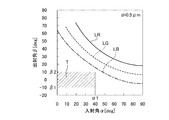
図13、図14、図15は、このような前提のもと、上記の数式(1)を用いて、溝ピッチdを1μm、0.5μm、0.4μmとした場合のそれぞれについて、入射角αと出射角βとを算出し、アイレンジER内での結像の有無を評価した線図である。ここでは、m=1を想定する。図13、図14、図15は、可視光域成分の回折光として、波長λが650nmである赤色光、波長λが550nmである緑色光、波長λが450nmである青色光の回折光がアイレンジER内で結像するか否かについて評価している。図13、図14、図15中、線LBは、上記青色光が入射角αで溝5dに入射した場合の回折光の出射角βの特性を表し、線LGは、上記緑色光が入射角αで溝5dに入射した場合の回折光の出射角βの特性を表し、線LRは、上記赤色光が入射角αで溝5dに入射した場合の回折光の出射角βの特性を表している。図13、図14、図15は、横軸における評価対象となるディスプレイ3からの出射光の角度範囲[0〜α1=0〜40度]と、縦軸におけるアイレンジERの角度範囲[β1〜β2=−10度〜10度]とによって規定される評価対象領域Tに、各線LR、LG、LBが入らなければ、アイレンジER内の目視位置にて当該波長の光の回折光が結像しない、すなわち、虚像が現れないことを表している。   FIG. 13, FIG. 14 and FIG. 15 show the incident angle for each of the cases where the groove pitch d is 1 μm, 0.5 μm and 0.4 μm using the above formula (1) under the above assumption. FIG. 6 is a diagram in which α and an emission angle β are calculated, and the presence or absence of image formation in the eye range ER is evaluated. Here, m = 1 is assumed. 13, 14, and 15 show diffracted light of visible light component as red light having a wavelength λ of 650 nm, green light having a wavelength λ of 550 nm, and blue light having a wavelength λ of 450 nm. Whether or not an image is formed within the range ER is evaluated. 13, 14, and 15, a line LB represents a characteristic of an emission angle β of the diffracted light when the blue light is incident on the groove 5 d at an incident angle α, and a line LG represents the incident angle of the green light. The line LR represents the characteristic of the exit angle β of the diffracted light when incident on the groove 5d at α, and the line LR represents the characteristic of the exit angle β of the diffracted light when the red light enters the groove 5d at the incident angle α. Yes. 13, 14, and 15 show the angle range [0 to α1 = 0 to 40 degrees] of the light emitted from the display 3 to be evaluated on the horizontal axis and the angle range [β1 to the eye range ER on the vertical axis. If the lines LR, LG, and LB do not enter the evaluation target region T defined by β2 = −10 degrees to 10 degrees], the diffracted light of the light of the wavelength is imaged at the viewing position in the eye range ER. No, that is, no virtual image appears.

図13に示すように、溝ピッチdを1μm(d=1μm)とした場合、線LR、LG、LBのすべてが評価対象領域Tにかかっていることから、赤色光、緑色光、及び、青色光のすべてについて、アイレンジER内の目視位置にて回折光が結像し、虚像が現れることとなる(図9で説明した状態に相当する。)。一方、図14に示すように、溝ピッチdを0.5μm(d=0.5μm)とした場合、線LR、LG、LBのすべてが評価対象領域Tから外れていることから、赤色光、緑色光、及び、青色光のすべてについて、アイレンジER内の目視位置にて回折光が結像せず、虚像が現れないこととなる(図10で説明した状態に相当する。)。図15に示すように、溝ピッチdを0.4μm(d=0.4μm)とした場合には、図14の場合と比較して、さらに線LR、LG、LBが評価対象領域Tから離間し、赤色光、緑色光、及び、青色光のすべてについて、アイレンジER内の目視位置にて回折光が結像せず、虚像が現れない。このように、表示装置1は、上記のような前提のもとでは、少なくとも複数の微細な溝5dの溝ピッチdを0.5μm以下とすることで、アイレンジER内の目視位置にて回折光が結像せず、虚像が現れないようにすることができる。   As shown in FIG. 13, when the groove pitch d is 1 μm (d = 1 μm), all of the lines LR, LG, and LB are on the evaluation target region T, so that red light, green light, and blue light For all of the light, diffracted light forms an image at a viewing position in the eye range ER, and a virtual image appears (corresponding to the state described in FIG. 9). On the other hand, as shown in FIG. 14, when the groove pitch d is 0.5 μm (d = 0.5 μm), all of the lines LR, LG, and LB are out of the evaluation target region T. For all of the green light and the blue light, the diffracted light does not form an image at the viewing position in the eye range ER, and the virtual image does not appear (corresponding to the state described in FIG. 10). As shown in FIG. 15, when the groove pitch d is 0.4 μm (d = 0.4 μm), the lines LR, LG, and LB are further separated from the evaluation target region T compared to the case of FIG. However, for all of red light, green light, and blue light, diffracted light does not form an image at a viewing position in the eye range ER, and a virtual image does not appear. As described above, the display device 1 is diffracted at the visual position in the eye range ER by setting the groove pitch d of the plurality of fine grooves 5d to 0.5 μm or less under the above assumption. It is possible to prevent the light from being imaged and the virtual image from appearing.

以上で説明した表示装置1によれば、光を出射し車両情報を表示する第1表示面51、ここでは、車両情報に関する実像画像51aを表示する第1表示面51と、第1表示面51に重ねて設けられ第1表示面51から出射された光を透過すると共に実像図柄52aを構成する溝5dが形成された第2表示面52とを備え、溝5dは、第1表示面51から出射され当該溝5dで回折した可視光域成分の回折光が車両に応じて予め定まるアイレンジER内で結像しない溝ピッチdで複数形成される。   According to the display device 1 described above, the first display surface 51 that emits light and displays vehicle information, here, the first display surface 51 that displays a real image 51a related to vehicle information, and the first display surface 51. And a second display surface 52 formed with a groove 5d forming a real image pattern 52a and transmitting the light emitted from the first display surface 51. The groove 5d is formed from the first display surface 51. A plurality of diffracted light components of the visible light region that are emitted and diffracted by the groove 5d are formed at a groove pitch d that does not form an image within an eye range ER that is predetermined according to the vehicle.

したがって、表示装置1は、第1表示面51に表示される車両情報に関する実像画像51aと、第1表示面51に重ねて設けられ第1表示面51から出射された光を透過する第2表示面52に形成された実像図柄52aとを組み合わせた表示を行うことができる。この場合、表示装置1は、第2表示面52の実像図柄52aを構成する溝5dが所定の溝ピッチdで複数形成されるので、第1表示面51から出射され当該溝5dで回折した可視光域成分の回折光が車両に応じて予め定まるアイレンジER内で結像しないようにすることができる。この結果、表示装置1は、アイレンジER内の目視位置にて、当該第1表示面51で表示されている実像画像51aの虚像が視認されることを抑制することができるので、適正な視認性を確保することができる。例えば、表示装置1は、第2表示面52が非表示状態であるときに、第2表示面52の背面側の第1表示面51の実像画像51aがぼやけて見え難くなることを抑制することができ、第2表示面52を介して実像画像51aを明瞭に透過することができる。   Therefore, the display device 1 is provided with a real image 51a relating to vehicle information displayed on the first display surface 51 and a second display that is provided so as to overlap the first display surface 51 and transmits light emitted from the first display surface 51. A combination of the real image pattern 52a formed on the surface 52 can be displayed. In this case, since the display device 1 has a plurality of grooves 5d forming the real image pattern 52a of the second display surface 52 at a predetermined groove pitch d, the visible light emitted from the first display surface 51 and diffracted by the grooves 5d is visible. It is possible to prevent the diffracted light of the light region component from forming an image within the eye range ER that is predetermined according to the vehicle. As a result, the display device 1 can prevent the virtual image of the real image 51a displayed on the first display surface 51 from being visually recognized at the viewing position in the eye range ER. Sex can be secured. For example, when the second display surface 52 is in a non-display state, the display device 1 prevents the real image 51a of the first display surface 51 on the back side of the second display surface 52 from being blurred and difficult to see. The real image 51a can be clearly transmitted through the second display surface 52.

ここでは、以上で説明した表示装置1によれば、第1表示面51と第2表示面52への光の入射面と第2表示面52からの光の出射面とは、互いに平行であり、溝5dは、水平方向に延在し、溝ピッチdが0より大きく0.5μm以下とされることで、第1表示面51と当該第1表示面51の法線L5との交点Pを基準として、鉛直方向に当該第1表示面51の法線L5を中心とした20度の角度範囲内に、第1表示面51から出射され当該溝5dで回折した可視光域成分の回折光を結像させない。溝ピッチdの下限値は、より好ましくは製造上可能な寸法、例えば、0.1μm程度とするとよい。したがって、表示装置1は、上記のような前提のもと、溝ピッチdが0より大きく0.5μm以下となるように複数の溝5dが形成されることで、第1表示面51から出射され当該溝5dで回折した可視光域成分の回折光が上記の角度範囲内、典型的には、車両に応じて予め定まるアイレンジER内で結像しないようにすることができる。これにより、表示装置1は、上記の角度範囲内、典型的には、アイレンジER内の目視位置にて、当該第1表示面51で表示されている実像画像51aの虚像が視認されることを確実に抑制することができるので、適正な視認性を確保することができる。   Here, according to the display device 1 described above, the light incident surface on the first display surface 51 and the second display surface 52 and the light emission surface from the second display surface 52 are parallel to each other. The groove 5d extends in the horizontal direction, and the groove pitch d is set to be greater than 0 and equal to or less than 0.5 μm, whereby an intersection P between the first display surface 51 and the normal line L5 of the first display surface 51 is set. As a reference, the diffracted light of the visible light region component emitted from the first display surface 51 and diffracted by the groove 5d within an angle range of 20 degrees centered on the normal line L5 of the first display surface 51 in the vertical direction. Do not focus. The lower limit value of the groove pitch d is more preferably a dimension that can be manufactured, for example, about 0.1 μm. Accordingly, the display device 1 emits light from the first display surface 51 by forming the plurality of grooves 5d so that the groove pitch d is greater than 0 and equal to or less than 0.5 μm based on the above assumption. It is possible to prevent the diffracted light of the visible light region component diffracted by the groove 5d from forming an image within the above-mentioned angle range, typically within an eye range ER that is predetermined in accordance with the vehicle. As a result, the display device 1 visually recognizes the virtual image of the real image 51a displayed on the first display surface 51 at the viewing position within the above-described angle range, typically within the eye range ER. Therefore, appropriate visibility can be ensured.

さらに、以上で説明した表示装置1によれば、溝ピッチdは、第1表示面51から出射され溝5dで回折した可視光域成分の回折光が予め設定される所定の領域、ここでは、第1表示面51と当該第1表示面51の法線L5との交点Pを基準として、鉛直方向に当該第1表示面51の法線L5を中心とした20度の角度範囲内、典型的には、アイレンジER内で結像しない範囲で最大とされることが好ましい。これにより、表示装置1は、第1表示面51から出射され当該溝5dで回折した可視光域成分の回折光が車両に応じて予め定まる領域内、ここでは、アイレンジER内で結像しない溝ピッチdとした上で、当該溝ピッチdをできる限り大きくすることで、第2表示面52の表示状態にて、実像図柄52aを構成する溝5dで反射する光の光量をできる限り多くすることができる。この結果、表示装置1は、アイレンジER内の目視位置にて、当該第1表示面51で表示されている実像画像51aの虚像が視認されることを抑制した上で、第2表示面52の表示状態において実像図柄52aを明瞭に表示することができ、この点でも適正な視認性を確保することができる。また、表示装置1は、溝ピッチdをできる限り大きくすることで、例えば、当該微細な溝5dの加工コストを抑制し、製造コストを抑制することができる。   Furthermore, according to the display device 1 described above, the groove pitch d is a predetermined region in which the diffracted light of the visible light region component emitted from the first display surface 51 and diffracted by the groove 5d is set in advance, With reference to the intersection P between the first display surface 51 and the normal line L5 of the first display surface 51, the vertical direction is typically within an angle range of 20 degrees centered on the normal line L5 of the first display surface 51. In this case, it is preferable that the maximum is within a range where no image is formed within the eye range ER. As a result, the display device 1 does not form an image in an area where the diffracted light of the visible light region emitted from the first display surface 51 and diffracted by the groove 5d is predetermined according to the vehicle, in this case, in the eye range ER. By setting the groove pitch d as large as possible after setting the groove pitch d, the amount of light reflected by the grooves 5d constituting the real image pattern 52a is increased as much as possible in the display state of the second display surface 52. be able to. As a result, the display device 1 suppresses the virtual image of the real image 51a displayed on the first display surface 51 from being visually recognized at the viewing position in the eye range ER, and then the second display surface 52. In this display state, the real image pattern 52a can be clearly displayed, and appropriate visibility can be ensured also in this respect. Moreover, the display apparatus 1 can suppress the processing cost of the said fine groove | channel 5d, for example, and can suppress manufacturing cost by enlarging the groove pitch d as much as possible.

さらに、以上で説明した表示装置1によれば、第1表示面51は、一方向に偏光された光によって車両情報、ここでは車両情報に関する実像画像51aを表示し、溝5dは、偏向された光の偏光方向L1と交差する方向に延在する。したがって、表示装置1は、第2表示面52の非表示状態にて表示状態と比較して実像図柄52aを構成する溝5d自体を視認し難くすることができる。   Furthermore, according to the display device 1 described above, the first display surface 51 displays vehicle information, here, a real image 51a relating to vehicle information by light polarized in one direction, and the groove 5d is deflected. It extends in a direction intersecting with the polarization direction L1 of the light. Therefore, the display device 1 can make it difficult to visually recognize the groove 5d itself constituting the real image pattern 52a in the non-display state of the second display surface 52 as compared with the display state.

より詳細には、以上で説明した表示装置1によれば、一方向に偏光された光を照射し画像(実像画像51a)を表示する画像表示面3aを有するディスプレイ3と、画像表示面3aに重ねて設けられディスプレイ3から照射された光を透過すると共に図柄5c(実像図柄52a)を構成する溝5dが形成された透明導光板5a、及び、透明導光板5aの端面に光を照射する光源5bを有し、光源5bの点灯、消灯に基づいて、図柄5cの表示、非表示が切り替えられる重畳表示装置5とを備える。そして、ディスプレイ3の偏光方向L1と溝5dの延在方向L2とは、75°以上105°以下の角度範囲で交差する。これにより、この表示装置1によれば、ディスプレイ3の偏光方向L1と溝5dの延在方向L2とは、光源5bが消灯され画像表示面3aに画像が表示された状態で、透明導光板5aにおける図柄5cの周囲の領域の輝度に対する図柄5cの領域の輝度の輝度比が90%以上100%以下となる角度範囲で交差する構成となる。なお、透明導光板5aは、図柄5cの領域の材質の透過率と図柄5cの周囲の領域の材質の透過率とが同等となるように構成されている。   More specifically, according to the display device 1 described above, the display 3 having the image display surface 3a that irradiates light polarized in one direction and displays an image (real image 51a), and the image display surface 3a. A transparent light guide plate 5a in which grooves 5d constituting the design 5c (real image design 52a) are formed and light is applied to the end surface of the transparent light guide plate 5a while transmitting the light irradiated from the display 3 in an overlapping manner. 5b, and a superimposed display device 5 that can switch between display and non-display of the symbol 5c based on turning on and off of the light source 5b. The polarization direction L1 of the display 3 and the extending direction L2 of the groove 5d intersect at an angle range of 75 ° to 105 °. Thus, according to the display device 1, the polarization direction L1 of the display 3 and the extending direction L2 of the groove 5d are such that the light source 5b is turned off and an image is displayed on the image display surface 3a. The luminance ratio of the luminance of the area of the symbol 5c to the luminance of the area around the symbol 5c in FIG. The transparent light guide plate 5a is configured such that the transmittance of the material in the area of the symbol 5c is equal to the transmittance of the material in the area around the symbol 5c.

したがって、表示装置1は、ディスプレイ3の画像表示面3a上の画像(実像画像51a)の表示と、画像表示面3aに重ねて設けられた重畳表示装置5の透明導光板5a上の図柄5c(実像図柄52a)の表示とを組み合わせて多様な表示態様を実現することができる。そして、この表示装置1は、ディスプレイ3の偏光方向L1と溝5dの延在方向L2とが所定の角度範囲で交差するように構成されることから、透明導光板5a上の図柄5cを非表示とした場合に、透明導光板5aにおける図柄5cの周囲の領域の輝度に対する図柄5cの領域の輝度の輝度比を相対的に大きくすることができる。これにより、表示装置1は、光源5bを消灯し微細な溝5dによって構成された透明導光板5a上の図柄5cを非表示とした場合に、透明導光板5a上の図柄5cを構成する溝5dを視認されにくくすることができ、ディスプレイ3の画像表示面3a上に表示される画像の視認性が阻害されることを抑制することができる。この結果、この表示装置1は、例えば、多様な表示を実現した上で、適正な視認性を確保することができる。   Therefore, the display device 1 displays the image (real image 51a) on the image display surface 3a of the display 3, and the symbol 5c on the transparent light guide plate 5a of the superimposed display device 5 provided to overlap the image display surface 3a ( Various display modes can be realized by combining the display of the real image pattern 52a). And this display apparatus 1 is comprised so that the polarization direction L1 of the display 3 and the extending direction L2 of the groove | channel 5d may cross | intersect within a predetermined angle range, Therefore The pattern 5c on the transparent light-guide plate 5a is not displayed. In this case, the luminance ratio of the luminance of the area of the symbol 5c to the luminance of the area around the symbol 5c in the transparent light guide plate 5a can be relatively increased. Thus, when the display device 1 turns off the light source 5b and hides the symbol 5c on the transparent light guide plate 5a constituted by the fine grooves 5d, the groove 5d constituting the symbol 5c on the transparent light guide plate 5a. Can be prevented from being visually recognized, and the visibility of the image displayed on the image display surface 3a of the display 3 can be suppressed from being hindered. As a result, the display device 1 can ensure proper visibility, for example, while realizing various displays.

つまり、表示装置1は、ディスプレイ3の画像表示面3aの前面側に図柄5cの意匠を表示し、背景の画像表示面3a上の画像情報と図柄5cの意匠とを立体的に組み合わせて表示できるので、例えば、立体的で斬新な表示を行うことができる。その上で、表示装置1は、微細な溝5dによって図柄5cが構成される重畳表示装置5において、光源5bの消灯時に図柄5cの意匠が見えにくくなり、透明導光板5aの背景の画像表示面3aを見通すことができ、必要に応じて光源5bの点灯時に図柄5cの意匠が現れるようにすることができる。   That is, the display device 1 can display the design of the design 5c on the front side of the image display surface 3a of the display 3, and can display the image information on the background image display surface 3a and the design of the design 5c in a three-dimensional combination. Therefore, for example, a stereoscopic and novel display can be performed. In addition, in the display device 1, the design of the design 5 c becomes difficult to see when the light source 5 b is turned off in the superimposed display device 5 in which the design 5 c is configured by the fine grooves 5 d, and the background image display surface of the transparent light guide plate 5 a is displayed. 3a can be seen, and the design of the pattern 5c can appear when the light source 5b is turned on as necessary.

また、以上で説明した表示装置1によれば、ディスプレイ3の偏光方向L1と溝5dの延在方向L2とは、直交する。したがって、表示装置1は、透明導光板5a上の図柄5cを非表示とした場合に、図柄5cの周囲の領域に対する図柄5cの領域の輝度比が最大になるようにすることができる。これにより、表示装置1は、透明導光板5a上の図柄5cを非表示とした場合に、確実に溝5dを視認されにくくすることができ、ディスプレイ3の画像表示面3a上に表示される画像の視認性が阻害されることを確実に抑制することができる。   Further, according to the display device 1 described above, the polarization direction L1 of the display 3 and the extending direction L2 of the groove 5d are orthogonal to each other. Accordingly, the display device 1 can maximize the luminance ratio of the area of the symbol 5c to the area around the symbol 5c when the symbol 5c on the transparent light guide plate 5a is not displayed. Accordingly, the display device 1 can reliably prevent the groove 5d from being visually recognized when the symbol 5c on the transparent light guide plate 5a is not displayed, and an image displayed on the image display surface 3a of the display 3 It is possible to reliably prevent the visibility of the image from being hindered.

さらに、以上で説明した表示装置1によれば、溝5dの延在方向L2と光源5bによる光の照射方向L3とは、直交する。したがって、表示装置1は、光源5bからの光を、図柄5cを構成する溝5dに対してほぼ垂直に入射するようにすることができるので、透明導光板5a上に図柄5cを表示する場合に、溝5dで前面側(運転席側)に反射される光の量を相対的に増加させることができ、当該図柄5cを鮮明に表示することができる。   Furthermore, according to the display device 1 described above, the extending direction L2 of the groove 5d and the light irradiation direction L3 by the light source 5b are orthogonal to each other. Therefore, the display device 1 can make the light from the light source 5b incident substantially perpendicularly to the grooves 5d constituting the design 5c, so that the design 5c is displayed on the transparent light guide plate 5a. The amount of light reflected to the front side (driver's seat side) by the groove 5d can be relatively increased, and the symbol 5c can be clearly displayed.

さらに、以上で説明した表示装置1によれば、ディスプレイ3の偏光方向L1、及び、光源5bによる光の照射方向L3は、鉛直方向に沿った方向であり、溝5dの延在方向L2は、水平方向に沿った方向であり、透明導光板5aは、水平方向の長さが鉛直方向の長さより長く形成され、光源5bは、透明導光板5aの鉛直方向下側又は鉛直方向上側に配置される。したがって、表示装置1は、光源5bを溝5dに近接させて配置し、溝5dの延在方向L2と光源5bによる光の照射方向L3とを直交させ、光源5bからの光を溝5dに対してほぼ垂直に入射させる構成を、よりコンパクトに実現することができる。   Further, according to the display device 1 described above, the polarization direction L1 of the display 3 and the light irradiation direction L3 by the light source 5b are directions along the vertical direction, and the extending direction L2 of the groove 5d is: The transparent light guide plate 5a has a horizontal length longer than the vertical length, and the light source 5b is disposed on the lower side in the vertical direction or the upper side in the vertical direction of the transparent light guide plate 5a. The Therefore, the display device 1 arranges the light source 5b close to the groove 5d, makes the extending direction L2 of the groove 5d orthogonal to the light irradiation direction L3 of the light source 5b, and causes the light from the light source 5b to be directed to the groove 5d. Therefore, the configuration in which light is incident substantially perpendicularly can be realized more compactly.

なお、上述した本発明の実施形態に係る表示装置は、上述した実施形態に限定されず、特許請求の範囲に記載された範囲で種々の変更が可能である。   The display device according to the above-described embodiment of the present invention is not limited to the above-described embodiment, and various modifications can be made within the scope described in the claims.

以上の説明では、ディスプレイ3は、1つで構成されるものとして説明したが2つ以上が組み合わせられて構成されてもよい。   In the above description, the display 3 has been described as being configured by one, but may be configured by combining two or more.

以上で説明した表示装置1は、ディスプレイ3の偏光方向L1と溝5dの延在方向L2とが75°以上105°以下の角度範囲で交差するように構成され、言い換えれば、透明導光板5aにおける図柄5cの周囲の領域の輝度に対する図柄5cの領域の輝度の輝度比が90%以上100%以下となる角度範囲で交差するように構成されればよい。表示装置1は、例えば、ディスプレイ3の偏光方向L1が鉛直方向に対して傾斜していてもよく、この場合であってもディスプレイ3の偏光方向L1と溝5dの延在方向L2とが上記のような関係になっていればよい。   The display device 1 described above is configured such that the polarization direction L1 of the display 3 and the extending direction L2 of the groove 5d intersect at an angle range of 75 ° to 105 °, in other words, in the transparent light guide plate 5a. What is necessary is just to be comprised so that the brightness | luminance ratio of the brightness | luminance of the area | region of the pattern 5c with respect to the brightness | luminance of the area | region around the pattern 5c may cross | intersect in the angle range used as 90 to 100%. In the display device 1, for example, the polarization direction L1 of the display 3 may be inclined with respect to the vertical direction. Even in this case, the polarization direction L1 of the display 3 and the extending direction L2 of the groove 5d are the above-described directions. It only has to be a relationship like this.

以上の説明では、光源5bは、図柄5cが形成された領域の鉛直方向下側であって透明導光板5aの鉛直方向下側の端面と対向する位置に幅方向(水平方向)に沿って等間隔で3つが設けられ、鉛直方向上側に向けて光を照射するものとして説明したが、これに限らず、透明導光板5aの鉛直方向上側に設けられてもよいし、透明導光板5aの幅方向側方に設けられてもよい。   In the above description, the light source 5b is located along the width direction (horizontal direction) at a position on the lower side in the vertical direction of the region where the pattern 5c is formed and facing the lower end surface of the transparent light guide plate 5a in the vertical direction. Although it has been described that three are provided at intervals and irradiate light toward the upper side in the vertical direction, the present invention is not limited thereto, and may be provided on the upper side in the vertical direction of the transparent light guide plate 5a, or the width of the transparent light guide plate 5a. It may be provided in the direction side.

以上の説明では、溝5dは、水平方向に延在するものとして説明したがこれに限らない。例えば、溝5dが鉛直方向に延在する場合、溝5dに入射した光は、鉛直方向に延在する溝5dによって水平方向に沿って回折することになる。この場合、溝5dによる回折光の結像の有無を評価する際には、アイレンジERとして、水平方向に沿った所定の角度範囲を想定すればよい。   In the above description, the groove 5d has been described as extending in the horizontal direction, but the present invention is not limited thereto. For example, when the groove 5d extends in the vertical direction, the light incident on the groove 5d is diffracted along the horizontal direction by the groove 5d extending in the vertical direction. In this case, when evaluating the presence / absence of image formation of diffracted light by the groove 5d, a predetermined angular range along the horizontal direction may be assumed as the eye range ER.

例えば、以上で説明した図柄5cを構成する溝5dは、透明導光板5aの奥行き方向前面側の主面上に形成されてもよく、当該透明導光板5aの奥行き方向前面側の主面が第2表示面52を構成してもよい。   For example, the groove 5d constituting the symbol 5c described above may be formed on the main surface on the front side in the depth direction of the transparent light guide plate 5a, and the main surface on the front side in the depth direction of the transparent light guide plate 5a is first. Two display surfaces 52 may be configured.

また、以上で説明した表示装置1は、図1に示すように、第2表示面52を構成する部材である透明導光板5aの端面の所定の部位に反射材57が設けられることで、さらなる適正な視認性を確保するようにしてもよい。具体的には、反射材57は、第2表示面52を構成する透明導光板5aの端面であって光源5bからの光が入射する入射端面と当該光の照射方向に対向する端面に設けられる。ここでは、反射材57は、透明導光板5aの鉛直方向上側の端面であって鉛直方向に光源5bと対向する端面に設けられる。反射材57は、光源5bからの光を凹凸部としての溝5d側に反射する。反射材57は、例えば、ホットスタンプ箔、ミラー箔等によって構成されるが、これに限らず光源5bからの光を溝5d側に反射する材料であればなんでもよい。これにより、表示装置1は、透明導光板5aの入射端面と当該光の照射方向に対向する端面に設けられた反射材57によって、光源5bからの光を溝5d側に反射することで、当該溝5dで反射する光量を相対的に多くすることができる。この結果、表示装置1は、溝5dによって形成される実像図柄52aにおける輝度が不足することを抑制することができ、当該実像図柄52aが視認し難くなること抑制することができるので、適正な視認性を確保することができる。特に、表示装置1は、第2表示面52の背面側の第1表示面51でも実像画像51aを表示する構成であり、また、複数の微細な溝5dの溝ピッチdを0.5μm以下とすることで当該微細な溝5dで反射する光量が相対的に少なくなりやすい構成であることから、表示状態において、第2表示面52で表示される実像図柄52aが見え難くなる傾向にある。これに対して、表示装置1は、上記のように反射材57を備えることで、第2表示面52の表示状態において凹凸部(溝5d)で反射する光量を相対的に多くすることができるので、このような構造であっても適正な視認性を確保することができる。また、表示装置1は、反射材57の作用によって実像図柄52aの輝度ムラを抑制することもできるので、この点でも適正な視認性を確保することができる。   In addition, as shown in FIG. 1, the display device 1 described above is further provided with a reflective member 57 at a predetermined portion of the end surface of the transparent light guide plate 5 a that is a member constituting the second display surface 52. You may make it ensure appropriate visibility. Specifically, the reflective member 57 is provided on the end face of the transparent light guide plate 5a constituting the second display surface 52, and on the end face facing the incident direction of the light incident from the light source 5b. . Here, the reflective member 57 is provided on the end surface on the upper side in the vertical direction of the transparent light guide plate 5a and facing the light source 5b in the vertical direction. The reflective material 57 reflects the light from the light source 5b toward the groove 5d as an uneven portion. The reflector 57 is made of, for example, a hot stamp foil, a mirror foil, or the like, but is not limited thereto, and any material that reflects light from the light source 5b toward the groove 5d may be used. Thereby, the display device 1 reflects the light from the light source 5b to the groove 5d side by the reflecting material 57 provided on the end surface facing the incident end surface of the transparent light guide plate 5a and the light irradiation direction. The amount of light reflected by the groove 5d can be relatively increased. As a result, the display device 1 can suppress the luminance of the real image symbol 52a formed by the grooves 5d from being insufficient, and can suppress the real image symbol 52a from becoming difficult to visually recognize. Sex can be secured. In particular, the display device 1 is configured to display the real image 51a on the first display surface 51 on the back side of the second display surface 52, and the groove pitch d of the plurality of fine grooves 5d is 0.5 μm or less. As a result, the amount of light reflected by the minute groove 5d tends to be relatively small, and thus the real image pattern 52a displayed on the second display surface 52 tends to be difficult to see in the display state. On the other hand, the display device 1 includes the reflector 57 as described above, so that the amount of light reflected by the uneven portion (groove 5d) in the display state of the second display surface 52 can be relatively increased. Therefore, even if it is such a structure, appropriate visibility can be ensured. Moreover, since the display apparatus 1 can also suppress the luminance unevenness of the real image pattern 52a by the action of the reflecting material 57, it is possible to ensure appropriate visibility also in this respect.

また、以上の説明では、第1表示面51は、一方向に偏光された光によって、車両情報として、車両情報に関する実像画像51aを表示するものとして説明したがこれに限らず、実像画像51a以外で車両情報を表示するものであってもよい。図16に示す変形例に係る表示装置201は、アナログ計器、及び、その文字板の表面(奥行き方向前面側の面)によって第1表示面251が構成される。この場合、表示装置201は、典型的には、奥行き方向背面側から前面側に向かって、背面側光源260、偏光板261、文字板262、指針263、重畳表示装置5の透明導光板5aの順で積層された構造となっている。図16の例では、微細な溝5dによって形成される図柄5c(実像図柄52a)は、例えば、「注意マーク(三角形の中に感嘆符(エクスクラメーション・マーク)を模したアイコン)」であり、溝5dの延在方向L2は、水平方向に沿った方向である。第2表示面52は、図柄5cを構成する溝5dが形成された透明導光板5aの奥行き方向背面側の主面によって構成される。   In the above description, the first display surface 51 is described as displaying the real image 51a related to the vehicle information as the vehicle information by the light polarized in one direction. However, the present invention is not limited to this, and other than the real image 51a. The vehicle information may be displayed. In the display device 201 according to the modification shown in FIG. 16, the first display surface 251 is configured by the analog instrument and the surface of the dial (the surface on the front side in the depth direction). In this case, the display device 201 typically has a rear light source 260, a polarizing plate 261, a dial 262, a pointer 263, and the transparent light guide plate 5a of the superimposed display device 5 from the rear side in the depth direction to the front side. The structure is laminated in order. In the example of FIG. 16, the pattern 5c (real image pattern 52a) formed by the minute groove 5d is, for example, “attention mark (an icon that imitates an exclamation mark in an triangle)”. The extending direction L2 of the groove 5d is a direction along the horizontal direction. The 2nd display surface 52 is comprised by the main surface of the depth direction back side of the transparent light-guide plate 5a in which the groove | channel 5d which comprises the pattern 5c was formed.

そして、背面側光源260、文字板262、指針263は、車両に関する種々の計測値を当該指針263によってアナログ式で表示するアナログ計器(ここでは一例として回転計であるがこれに限らない。)を構成する。背面側光源260は、筐体2(図1等参照)内に設けられ奥行き方向背面側から前面側に向けて光を照射するものである。ここでは、背面側光源260、1つを図示しているが複数設けられてもよい。背面側光源260は、例えば、LED素子等によって構成されるがこれに限らない。文字板262は、表示する車両情報に応じた種々の図柄、記号、文字列等が描かれた板状の部材であり、略矩形状に形成され、背面側光源260の奥行き方向前面側に設けられる。文字板262は、例えば、透明生地のポリカーボネイト製シートであり、暗色系のインクによって、上記図柄、記号、文字列等に対応した形状が中抜きされた印刷が施される。文字板262は、背面側光源260から光が照射され、図柄、記号、文字列等が描かれた部分において当該照射された光が透過されることで、当該図柄、記号、文字列等が点灯表示される。文字板262は、車両情報に関する図柄、記号、文字列として、例えば、指標部262aや報知記号262bが形成されている。文字板262は、指標部262a、各種報知記号262bの部分が上述の中抜きされた部分であり、すなわち、光を透過する部分である。指標部262aは、背面側光源260から照射される光を透過し指針263によって指し示されるものである。各指標部262aは、指針263の先端の回動軌跡に沿った円弧、当該円弧に沿って等間隔で付された複数の目盛、数字等を含んで構成される。各報知記号262bは、警告する必要がある事象に対応して点灯するいわゆる各種の警告灯(ウォーニングランプ、いわゆるテルテール)等を含んで構成され、背面側光源260から照射される光を透過し当該背面側光源260の点灯、消灯に基づいて表示、非表示が切り替えられるものである。指針263は、文字板262の奥行き方向前面側に位置し、筐体2(図1等参照)内に設けられるモータが駆動することで回動し、車両に関する種々の計測値(車速、回転数等)に応じて指標部262aの所定の位置を指し示す。本変形例の第1表示面251は、背面側光源260から照射される光を所定の形状で透過することで車両情報を表示する表示面であり、ここでは、指標部262a、報知記号262b等を含んで構成される文字板262の奥行き方向前面側の面によって構成される。   And the back side light source 260, the dial 262, and the pointer 263 are analog instruments (in this example, a tachometer, but not limited thereto) that display various measurement values related to the vehicle in an analog manner using the pointer 263. Configure. The back side light source 260 is provided in the housing 2 (see FIG. 1 and the like) and emits light from the back side in the depth direction toward the front side. Here, although one back side light source 260 is illustrated, a plurality of light sources may be provided. Although the back side light source 260 is comprised by the LED element etc., for example, it is not restricted to this. The dial plate 262 is a plate-like member on which various symbols, symbols, character strings, and the like corresponding to the vehicle information to be displayed are drawn, is formed in a substantially rectangular shape, and is provided on the front side in the depth direction of the back side light source 260. It is done. The dial plate 262 is, for example, a polycarbonate sheet made of a transparent fabric, and is printed with a dark color ink in which the shape corresponding to the design, symbol, character string, etc. is hollowed out. The dial 262 is irradiated with light from the back side light source 260, and the irradiated light is transmitted through a portion where the design, symbol, character string, etc. are drawn, so that the design, symbol, character string, etc. is lit. Is displayed. The dial 262 is formed with, for example, an indicator 262a and a notification symbol 262b as symbols, symbols, and character strings related to vehicle information. The dial 262 is a portion where the indicator portion 262a and the various notification symbols 262b are hollowed out, that is, a portion that transmits light. The indicator portion 262 a transmits light emitted from the back side light source 260 and is indicated by the pointer 263. Each indicator portion 262a is configured to include an arc along the turning trajectory of the tip of the pointer 263, a plurality of scales, numbers, and the like attached at equal intervals along the arc. Each of the notification symbols 262b includes so-called various warning lights (warning lamps, so-called telltales) that are turned on in response to an event that needs to be warned, and transmits the light emitted from the back side light source 260. The display and non-display can be switched based on whether the back side light source 260 is turned on or off. The pointer 263 is located on the front side in the depth direction of the dial 262, and is rotated by driving a motor provided in the housing 2 (see FIG. 1 and the like), so that various measurement values (vehicle speed, rotation speed) related to the vehicle are obtained. Etc.) to indicate a predetermined position of the indicator portion 262a. The first display surface 251 of this modification is a display surface that displays vehicle information by transmitting the light emitted from the back-side light source 260 in a predetermined shape. Here, the indicator portion 262a, the notification symbol 262b, etc. Is constituted by the surface on the front side in the depth direction of the dial plate 262 configured to include

偏光板261は、背面側光源260と透明導光板5aの第2表示面52との間に設けられ背面側光源260から第2表示面52に向けて照射された光を一方向に偏光された光にするものである。ここでは、偏光板261は、略矩形状に形成され、文字板262の奥行き方向背面側の面に設けられるが、文字板262の奥行き方向前面側の面に設けられてもよいし、透明導光板5aの奥行き方向背面側の面に設けられてもよい。偏光板261は、背面側光源260から発せられた光を、偏光方向L4(図16等参照)を透過軸方向として揃え、当該偏光方向L4(透過軸方向)に沿った振動方向の光を出射することで一方向に偏光された光を第2表示面52側に出射する。ここでは、偏光板261によって偏光された光の偏光方向L4は、鉛直方向に沿った方向とされている。つまり、溝5dの延在方向L2と偏光板261による偏光方向L4とは、直交する。この場合であっても、表示装置1は、溝5dが偏光方向L4と交差する方向に延在するようにして形成されることで、第2表示面52の非表示状態で実像図柄52aを構成する溝5dを見えにくい構造とすることができ、その上で、アイレンジER内の目視位置にて、当該第1表示面51で表示されている実像画像51aの虚像が視認されることを抑制することができ、適正な視認性を確保することができる。   The polarizing plate 261 is provided between the back side light source 260 and the second display surface 52 of the transparent light guide plate 5a, and polarized in one direction with respect to the light emitted from the back side light source 260 toward the second display surface 52. It is what makes it light. Here, the polarizing plate 261 is formed in a substantially rectangular shape and is provided on the surface of the dial 262 on the back side in the depth direction. However, the polarizing plate 261 may be provided on the surface of the dial 262 on the front side in the depth direction, or may be transparent. You may provide in the surface of the depth direction back side of the optical plate 5a. The polarizing plate 261 aligns the light emitted from the back-side light source 260 with the polarization direction L4 (see FIG. 16 etc.) as the transmission axis direction, and emits light in the vibration direction along the polarization direction L4 (transmission axis direction). As a result, light polarized in one direction is emitted to the second display surface 52 side. Here, the polarization direction L4 of the light polarized by the polarizing plate 261 is a direction along the vertical direction. That is, the extending direction L2 of the groove 5d and the polarization direction L4 by the polarizing plate 261 are orthogonal to each other. Even in this case, the display device 1 is configured so that the groove 5d extends in a direction intersecting with the polarization direction L4, so that the real image pattern 52a is configured in the non-display state of the second display surface 52. The groove 5d to be viewed can be made difficult to see, and the virtual image of the real image 51a displayed on the first display surface 51 is suppressed from being viewed at the viewing position in the eye range ER. It is possible to ensure proper visibility.

1、201 表示装置
5a 透明導光板
5b 光源
5c 図柄
5d 溝
51、251 第1表示面
51a 実像画像(画像)
52 第2表示面
52a 実像図柄(図柄)
261 偏光板
d 溝ピッチ
ER アイレンジ
L1、L4 偏光方向
L2 延在方向
L3 照射方向
L5、L6 法線
1,201 Display device 5a Transparent light guide plate 5b Light source 5c Pattern 5d Grooves 51, 251 First display surface 51a Real image (image)
52 2nd display surface 52a Real image design (design)
261 Polarizing plate d Groove pitch ER Eye range L1, L4 Polarization direction L2 Extension direction L3 Irradiation direction L5, L6 Normal line

Claims (3)

光を出射し車両情報に関する画像を表示する第1表示面と、
前記第1表示面に重ねて設けられ前記第1表示面から出射された光を透過すると共に図柄を構成する溝が形成された第2表示面とを備え、
前記第1表示面と前記第2表示面への光の入射面と前記第2表示面からの光の出射面とは、互いに平行であり、
前記溝は、水平方向に延在し、溝ピッチが0より大きく0.5μm以下とされることで、前記第1表示面と当該第1表示面の法線との交点を基準として、鉛直方向に当該第1表示面の法線を中心とした20度の角度範囲内に、前記第1表示面から出射され当該溝で回折した可視光域成分の回折光を結像させないことを特徴とする、
表示装置。
A first display surface for emitting light and displaying an image relating to vehicle information;
A second display surface provided on the first display surface so as to transmit light emitted from the first display surface and having a groove forming a symbol;
The light incident surface to the first display surface and the second display surface and the light emission surface from the second display surface are parallel to each other,
The groove extends in the horizontal direction, and the groove pitch is set to be greater than 0 and 0.5 μm or less, so that the vertical direction is based on the intersection of the first display surface and the normal line of the first display surface. In addition, the diffracted light of the visible light region component emitted from the first display surface and diffracted by the groove is not imaged within an angle range of 20 degrees centered on the normal line of the first display surface. ,
Display device.
前記溝ピッチは、前記第1表示面から出射され前記溝で回折した可視光域成分の回折光が予め設定される所定の領域内で結像しない範囲で最大とされる、
請求項1に記載の表示装置。
The groove pitch is maximized in a range where the diffracted light of the visible light region component emitted from the first display surface and diffracted by the groove does not form an image within a predetermined region set in advance.
The display device according to claim 1 .
前記第1表示面は、一方向に偏光された光によって前記車両情報を表示し、
前記溝は、前記偏向された光の偏光方向と交差する方向に延在する、
請求項1又は請求項2に記載の表示装置。
The first display surface displays the vehicle information by light polarized in one direction,
The groove extends in a direction intersecting a polarization direction of the deflected light;
The display device according to claim 1 .
JP2015111245A 2015-06-01 2015-06-01 Display device Active JP6232013B2 (en)

Priority Applications (3)

Application Number Priority Date Filing Date Title
JP2015111245A JP6232013B2 (en) 2015-06-01 2015-06-01 Display device
US15/163,283 US9983347B2 (en) 2015-06-01 2016-05-24 Display device
DE102016209086.0A DE102016209086B4 (en) 2015-06-01 2016-05-25 display device

Applications Claiming Priority (1)

Application Number Priority Date Filing Date Title
JP2015111245A JP6232013B2 (en) 2015-06-01 2015-06-01 Display device

Publications (2)

Publication Number Publication Date
JP2016223936A JP2016223936A (en) 2016-12-28
JP6232013B2 true JP6232013B2 (en) 2017-11-15

Family

ID=57281912

Family Applications (1)

Application Number Title Priority Date Filing Date
JP2015111245A Active JP6232013B2 (en) 2015-06-01 2015-06-01 Display device

Country Status (3)

Country Link
US (1) US9983347B2 (en)
JP (1) JP6232013B2 (en)
DE (1) DE102016209086B4 (en)

Families Citing this family (8)

* Cited by examiner, † Cited by third party
Publication number Priority date Publication date Assignee Title
WO2014199629A1 (en) * 2013-06-14 2014-12-18 株式会社デンソー Display device for vehicle
DE112014005403B4 (en) * 2013-11-26 2023-02-02 Yazaki Corporation Dial with radial lines and automotive dial with radial lines
CN113147580A (en) 2015-04-10 2021-07-23 麦克赛尔株式会社 Vehicle with image projection part
DE102017223657A1 (en) * 2017-12-22 2019-06-27 Zf Friedrichshafen Ag Transparent display for a switching device
JP6886442B2 (en) * 2018-09-07 2021-06-16 矢崎総業株式会社 Dial
DE102019120215A1 (en) * 2019-07-26 2021-01-28 Valeo Schalter Und Sensoren Gmbh Method and driver assistance system for providing visual information about a first vehicle in the vicinity of a second vehicle, computer program and computer-readable medium
CN113415235A (en) * 2021-07-26 2021-09-21 重庆长安汽车股份有限公司 Atmosphere lamp device for automobile instrument panel
KR20230066947A (en) * 2021-11-08 2023-05-16 현대모비스 주식회사 Lamp for vehicle

Family Cites Families (13)

* Cited by examiner, † Cited by third party
Publication number Priority date Publication date Assignee Title
JPH05319138A (en) * 1992-05-22 1993-12-03 Toyota Autom Loom Works Ltd Display device for vehicle
DE4244452C2 (en) 1992-12-23 1996-09-19 Porsche Ag Display instrument for motor vehicles
US6054932A (en) * 1998-11-20 2000-04-25 Gartner; William J. LED traffic light and method manufacture and use thereof
EP1666933A1 (en) * 2004-12-02 2006-06-07 Asulab S.A. Dual illumination function optical device and figurative image formation
US20070263137A1 (en) * 2006-05-09 2007-11-15 Victor Company Of Japan, Limited Illuminating device and display device
WO2009025034A1 (en) * 2007-08-22 2009-02-26 Pioneer Corporation Image display unit
US20100259485A1 (en) * 2009-04-08 2010-10-14 Cheng-Yen Chuang Touch keyboard input device enabling pattern switching
US20110194167A1 (en) * 2009-07-20 2011-08-11 Jeanette Elisabeth Jackson Multi-segmented displays
US8248265B2 (en) * 2009-09-17 2012-08-21 Toyota Motor Engineering & Manufacturing North America, Inc. Vehicle console display buttons and vehicle consoles incorporating the same
JP5413744B2 (en) 2010-07-30 2014-02-12 株式会社デンソー Display device
JP5925489B2 (en) * 2011-12-28 2016-05-25 株式会社恭和 Graphic system that improves the three-dimensional appearance of the liquid crystal display
US8764266B2 (en) * 2012-03-30 2014-07-01 GE Lighting Solutions, LLC Edge-lit flat panel repetitive lighting fixture
EP3427968B2 (en) * 2013-03-12 2023-03-01 Toppan Printing Co., Ltd. Display

Also Published As

Publication number Publication date
JP2016223936A (en) 2016-12-28
DE102016209086A1 (en) 2016-12-01
DE102016209086B4 (en) 2019-06-19
US9983347B2 (en) 2018-05-29
US20160347246A1 (en) 2016-12-01

Similar Documents

Publication Publication Date Title
JP6232013B2 (en) Display device
JP6646431B2 (en) Display device
JP6469666B2 (en) Display device
JP5323132B2 (en) Vehicle instrument
JP6510229B2 (en) Display device
JP6412795B2 (en) Display device
JP5659679B2 (en) Display device
JP6585430B2 (en) Display device
JP2009069087A (en) Display apparatus
JP6539512B2 (en) Display device
JP5601705B2 (en) In-vehicle display device
JP6856320B2 (en) Display device
JP2009150858A (en) Display device
JP6615156B2 (en) Vehicle display device
JP4637680B2 (en) Instrument
JP6286748B2 (en) Vehicle display device
JP5742729B2 (en) Pointer display device
JP2008196908A (en) Display panel for instrument
JP2009068858A (en) Display apparatus
JP2015025715A (en) Display device for vehicle
JP6384159B2 (en) Display device
JP6390324B2 (en) Display device
JP2014213662A (en) Display device for vehicle
WO2019054162A1 (en) Display device
JP2018008579A (en) Display device for vehicle

Legal Events

Date Code Title Description
A977 Report on retrieval

Free format text: JAPANESE INTERMEDIATE CODE: A971007

Effective date: 20170720

A131 Notification of reasons for refusal

Free format text: JAPANESE INTERMEDIATE CODE: A131

Effective date: 20170815

A521 Request for written amendment filed

Free format text: JAPANESE INTERMEDIATE CODE: A523

Effective date: 20170919

TRDD Decision of grant or rejection written
A01 Written decision to grant a patent or to grant a registration (utility model)

Free format text: JAPANESE INTERMEDIATE CODE: A01

Effective date: 20171010

A61 First payment of annual fees (during grant procedure)

Free format text: JAPANESE INTERMEDIATE CODE: A61

Effective date: 20171020

R150 Certificate of patent or registration of utility model

Ref document number: 6232013

Country of ref document: JP

Free format text: JAPANESE INTERMEDIATE CODE: R150

R250 Receipt of annual fees

Free format text: JAPANESE INTERMEDIATE CODE: R250

R250 Receipt of annual fees

Free format text: JAPANESE INTERMEDIATE CODE: R250

R250 Receipt of annual fees

Free format text: JAPANESE INTERMEDIATE CODE: R250

S531 Written request for registration of change of domicile

Free format text: JAPANESE INTERMEDIATE CODE: R313531

R350 Written notification of registration of transfer

Free format text: JAPANESE INTERMEDIATE CODE: R350

R250 Receipt of annual fees

Free format text: JAPANESE INTERMEDIATE CODE: R250