JP2016120565A - Image processing apparatus, image processing system, image processing method, and computer program - Google Patents
Image processing apparatus, image processing system, image processing method, and computer program Download PDFInfo
- Publication number
- JP2016120565A JP2016120565A JP2014262241A JP2014262241A JP2016120565A JP 2016120565 A JP2016120565 A JP 2016120565A JP 2014262241 A JP2014262241 A JP 2014262241A JP 2014262241 A JP2014262241 A JP 2014262241A JP 2016120565 A JP2016120565 A JP 2016120565A
- Authority
- JP
- Japan
- Prior art keywords
- image processing
- end effector
- robot
- selection
- robot controller
- Prior art date
- Legal status (The legal status is an assumption and is not a legal conclusion. Google has not performed a legal analysis and makes no representation as to the accuracy of the status listed.)
- Granted
Links
Images


Classifications
-
- B—PERFORMING OPERATIONS; TRANSPORTING
- B25—HAND TOOLS; PORTABLE POWER-DRIVEN TOOLS; MANIPULATORS
- B25J—MANIPULATORS; CHAMBERS PROVIDED WITH MANIPULATION DEVICES
- B25J9/00—Programme-controlled manipulators
- B25J9/16—Programme controls
- B25J9/1694—Programme controls characterised by use of sensors other than normal servo-feedback from position, speed or acceleration sensors, perception control, multi-sensor controlled systems, sensor fusion
- B25J9/1697—Vision controlled systems
-
- G—PHYSICS
- G05—CONTROLLING; REGULATING
- G05B—CONTROL OR REGULATING SYSTEMS IN GENERAL; FUNCTIONAL ELEMENTS OF SUCH SYSTEMS; MONITORING OR TESTING ARRANGEMENTS FOR SUCH SYSTEMS OR ELEMENTS
- G05B2219/00—Program-control systems
- G05B2219/30—Nc systems
- G05B2219/39—Robotics, robotics to robotics hand
- G05B2219/39369—Host and robot controller and vision processing
-
- G—PHYSICS
- G05—CONTROLLING; REGULATING
- G05B—CONTROL OR REGULATING SYSTEMS IN GENERAL; FUNCTIONAL ELEMENTS OF SUCH SYSTEMS; MONITORING OR TESTING ARRANGEMENTS FOR SUCH SYSTEMS OR ELEMENTS
- G05B2219/00—Program-control systems
- G05B2219/30—Nc systems
- G05B2219/39—Robotics, robotics to robotics hand
- G05B2219/39397—Map image error directly to robot movement, position with relation to world, base not needed, image based visual servoing
-
- G—PHYSICS
- G05—CONTROLLING; REGULATING
- G05B—CONTROL OR REGULATING SYSTEMS IN GENERAL; FUNCTIONAL ELEMENTS OF SUCH SYSTEMS; MONITORING OR TESTING ARRANGEMENTS FOR SUCH SYSTEMS OR ELEMENTS
- G05B2219/00—Program-control systems
- G05B2219/30—Nc systems
- G05B2219/39—Robotics, robotics to robotics hand
- G05B2219/39484—Locate, reach and grasp, visual guided grasping
-
- G—PHYSICS
- G05—CONTROLLING; REGULATING
- G05B—CONTROL OR REGULATING SYSTEMS IN GENERAL; FUNCTIONAL ELEMENTS OF SUCH SYSTEMS; MONITORING OR TESTING ARRANGEMENTS FOR SUCH SYSTEMS OR ELEMENTS
- G05B2219/00—Program-control systems
- G05B2219/30—Nc systems
- G05B2219/40—Robotics, robotics mapping to robotics vision
- G05B2219/40425—Sensing, vision based motion planning
-
- G—PHYSICS
- G05—CONTROLLING; REGULATING
- G05B—CONTROL OR REGULATING SYSTEMS IN GENERAL; FUNCTIONAL ELEMENTS OF SUCH SYSTEMS; MONITORING OR TESTING ARRANGEMENTS FOR SUCH SYSTEMS OR ELEMENTS
- G05B2219/00—Program-control systems
- G05B2219/30—Nc systems
- G05B2219/40—Robotics, robotics mapping to robotics vision
- G05B2219/40607—Fixed camera to observe workspace, object, workpiece, global
-
- Y—GENERAL TAGGING OF NEW TECHNOLOGICAL DEVELOPMENTS; GENERAL TAGGING OF CROSS-SECTIONAL TECHNOLOGIES SPANNING OVER SEVERAL SECTIONS OF THE IPC; TECHNICAL SUBJECTS COVERED BY FORMER USPC CROSS-REFERENCE ART COLLECTIONS [XRACs] AND DIGESTS
- Y10—TECHNICAL SUBJECTS COVERED BY FORMER USPC
- Y10S—TECHNICAL SUBJECTS COVERED BY FORMER USPC CROSS-REFERENCE ART COLLECTIONS [XRACs] AND DIGESTS
- Y10S901/00—Robots
- Y10S901/02—Arm motion controller
- Y10S901/09—Closed loop, sensor feedback controls arm movement
Landscapes
- Engineering & Computer Science (AREA)
- Robotics (AREA)
- Mechanical Engineering (AREA)
- Manipulator (AREA)
Abstract
Description
本発明は、複雑なロボット動作制御プログラムを逐一コーディングすることなく、高い精度でロボットの動作を制御することができる画像処理装置、画像処理システム、画像処理方法及びコンピュータプログラムに関する。 The present invention relates to an image processing apparatus, an image processing system, an image processing method, and a computer program that can control the operation of a robot with high accuracy without coding a complicated robot operation control program one by one.
撮像装置によりロボットの作業領域を撮像して、撮像された画像内のワークの位置を検出し、検出されたワークの位置情報を撮像された画像に基づいて算出することで、ロボットの動作を高い精度で制御する制御システムが多々開発されている。例えば特許文献1では、撮像装置を含むセンサにより検出された情報に基づいてロボットの動作を制御するロボット制御装置が開示されている。また、特許文献2では、外部のコンピュータでコンパイルしたロードモジュール(ロボット動作制御プログラム)を送信することでロボットの動作を制御するロボット制御装置が開示されている。
By picking up the work area of the robot with the image pickup device, detecting the position of the work in the picked-up image, and calculating the position information of the detected work based on the picked-up image, the operation of the robot is enhanced. Many control systems have been developed to control with precision. For example,
このように従来のロボット制御システムでは、精緻な動作制御をするべく、画像処理装置において表示される座標系で算出された位置座標を、ロボットコントローラがエンドエフェクタを動作させる座標系の位置座標へと座標変換している。座標変換を行うための変換式を算出する処理をキャリブレーションと呼んでいる。ここで、エンドエフェクタとは、例えばワークを把持して固着できるロボットアームの先端部分を意味する。 As described above, in the conventional robot control system, the position coordinate calculated in the coordinate system displayed on the image processing apparatus is changed to the position coordinate of the coordinate system in which the robot controller operates the end effector in order to perform precise motion control. The coordinates are converted. The process of calculating a conversion formula for performing coordinate conversion is called calibration. Here, the end effector means, for example, a tip portion of a robot arm that can hold and fix a workpiece.
ロボットのエンドエフェクタに対する動作(移動)命令は、画像処理装置が、撮像した画像に基づく位置座標を、キャリブレーション結果に基づいて実際の位置座標の座標値に変換する。画像処理装置は、変換された座標値とともに動作(移動)命令をロボットコントローラへ送信する。 In the operation (movement) command for the end effector of the robot, the image processing apparatus converts position coordinates based on the captured image into coordinate values of actual position coordinates based on the calibration result. The image processing apparatus transmits an operation (movement) command together with the converted coordinate values to the robot controller.
ロボットコントローラがロボットを正しく動作させるためには、ロボットの動作プログラムをユーザが作成する必要がある。動作プログラムには、例えばロボットのエンドエフェクタを原点位置に復帰させる、エンドエフェクタを特定の位置に移動させる、ワークを把持する、ワークを解放する等の一連の動作がシーケンシャルに記述されている。 In order for the robot controller to operate the robot correctly, it is necessary for the user to create a robot operation program. In the operation program, for example, a series of operations such as returning the end effector of the robot to the original position, moving the end effector to a specific position, gripping the workpiece, and releasing the workpiece are sequentially described.
しかし、ユーザは、画像処理装置とのデータ通信を含む一連の動作についてもプログラムを作成する必要があり、ロボットの動作を制御するためには、ロボットコントローラ用の動作プログラムだけでなく、画像処理装置が関連する一連の動作についてもプログラムを作成する必要が生じる。したがって、システム全体の立ち上げまでに相当の時間を要するという問題点があった。 However, the user needs to create a program for a series of operations including data communication with the image processing apparatus. In order to control the operation of the robot, not only the operation program for the robot controller but also the image processing apparatus It is necessary to create a program for a series of operations related to. Therefore, there is a problem that it takes a considerable time to start up the entire system.
本発明は斯かる事情に鑑みてなされたものであり、複雑なロボット動作制御プログラムを逐一コーディングすることなく、高い精度でロボットの動作を制御することができる画像処理装置、画像処理システム、画像処理方法及びコンピュータプログラムを提供することを目的とする。 The present invention has been made in view of such circumstances, and an image processing apparatus, an image processing system, and an image processing capable of controlling a robot operation with high accuracy without coding a complicated robot operation control program one by one. It is an object to provide a method and a computer program.
上記目的を達成するために第1発明に係る画像処理装置は、ロボットの動作を制御するロボットコントローラとデータ通信することが可能な通信装置と、前記ロボットによる操作対象である対象物を撮像する撮像装置とを有する画像処理装置であって、前記ロボットのエンドエフェクタの移動先の各位置座標である第一の座標値を取得する移動座標取得手段と、前記エンドエフェクタの各移動先にて対象物を撮像するよう前記撮像装置の動作を制御する撮像制御手段と、各移動先にて撮像された対象物の画像に基づいて、対象物の位置座標である第二の座標値を検出する画像検出手段と、少なくとも前記第一の座標値へ前記エンドエフェクタを移動させる動作又は前記第二の座標値へ前記エンドエフェクタを移動させる動作を含む複数の動作の中から、前記ロボットコントローラに実行させる複数の動作の選択を受け付け、選択を受け付けた複数の動作の実行順序の設定を受け付ける動作設定受付手段と、該動作設定受付手段で選択を受け付けた複数の動作それぞれに対応する動作プログラムを、設定を受け付けた実行順序に従って生成するプログラム生成手段とを備えることを特徴とする。 In order to achieve the above object, an image processing apparatus according to a first aspect of the present invention includes a communication device capable of data communication with a robot controller that controls the operation of a robot, and imaging for imaging an object that is an operation target by the robot. An image processing apparatus comprising: a movement coordinate acquisition unit configured to acquire a first coordinate value that is a position coordinate of each movement destination of the end effector of the robot; and a target object at each movement destination of the end effector. And image detection for detecting a second coordinate value, which is a position coordinate of the object, based on an image of the object imaged at each movement destination, and an imaging control means for controlling the operation of the imaging apparatus to image And a plurality of operations including an operation of moving the end effector to at least the first coordinate value or an operation of moving the end effector to the second coordinate value Receiving a selection of a plurality of operations to be executed by the robot controller, a setting receiving unit for receiving a setting of an execution order of the plurality of operations for which the selection has been received, and a plurality of operations receiving the selection by the operation setting receiving unit Program generating means for generating an operation program corresponding to each in accordance with an execution order in which settings are accepted is provided.
また、第2発明に係る画像処理装置は、第1発明において、前記プログラム生成手段は、設定を受け付けた実行順序に従って、選択を受け付けた複数の動作に対応する各動作プログラムを、編集可能なテキストデータとして生成することが好ましい。 In the image processing apparatus according to a second invention, in the first invention, the program generating means can edit each operation program corresponding to a plurality of operations for which the selection has been accepted in accordance with the execution order for which the setting has been accepted. It is preferable to generate as data.
また、第3発明に係る画像処理装置は、第1又は第2発明において、前記動作設定受付手段は、前記ロボットコントローラから受信する、前記撮像装置で対象物の撮像を開始するタイミングを示す撮像トリガ、又は処理切替命令ごとに、少なくとも動作の種類及び動作順序を含む動作条件の設定を受け付けることが好ましい。 An image processing apparatus according to a third aspect of the present invention is the image processing trigger according to the first or second aspect, wherein the operation setting accepting unit indicates timing to start capturing an object with the image capturing apparatus, which is received from the robot controller. Alternatively, it is preferable to accept the setting of operation conditions including at least the type of operation and the operation sequence for each process switching command.
また、第4発明に係る画像処理装置は、第3発明において、前記プログラム生成手段は、前記ロボットコントローラによる動作のうち、少なくとも前記第一の座標値又は前記第2の座標値へ前記エンドエフェクタを移動させる動作、前記撮像トリガを送信する動作を含む一連の複数の動作について動作プログラムを生成することが好ましい。 According to a fourth aspect of the present invention, in the third aspect, the program generation means moves the end effector to at least the first coordinate value or the second coordinate value among the operations by the robot controller. It is preferable to generate an operation program for a series of a plurality of operations including an operation to move and an operation to transmit the imaging trigger.
また、第5発明に係る画像処理装置は、第1乃至第4発明のいずれか1つにおいて、前記動作設定受付手段は、前記エンドエフェクタに対する待機指令の設定を受け付けることが好ましい。 In the image processing device according to a fifth aspect of the present invention, in any one of the first to fourth aspects, the operation setting accepting unit preferably accepts a setting of a standby command for the end effector.
また、第6発明に係る画像処理装置は、第1乃至第5発明のいずれか1つにおいて、前記ロボットの種別の選択を受け付けるロボット選択受付手段を備え、前記プログラム生成手段は、選択を受け付けた前記ロボットの種別ごとに規定されたフォーマットに従って前記動作プログラムを生成することが好ましい。 According to a sixth aspect of the present invention, in any one of the first to fifth aspects, the image processing apparatus includes a robot selection receiving unit that receives a selection of the type of the robot, and the program generation unit receives the selection. Preferably, the operation program is generated according to a format defined for each type of the robot.
また、第7発明に係る画像処理装置は、第1乃至第6発明のいずれか1つにおいて、前記プログラム生成手段は、前記ロボットコントローラとのデータ通信を確立する前記動作プログラムを生成することが好ましい。 In the image processing device according to a seventh aspect of the present invention, in any one of the first to sixth aspects, the program generation unit preferably generates the operation program for establishing data communication with the robot controller. .
また、第8発明に係る画像処理装置は、第1乃至第7発明のいずれか1つにおいて、前記第一の座標値又は前記第2の座標値へ前記エンドエフェクタを移動させる移動命令を前記ロボットコントローラへ送信する移動命令送信手段を備えることが好ましい。 An image processing apparatus according to an eighth aspect of the present invention is the image processing apparatus according to any one of the first to seventh aspects, wherein the robot has a movement command for moving the end effector to the first coordinate value or the second coordinate value. It is preferable to provide a movement command transmission means for transmitting to the controller.
また、第9発明に係る画像処理装置は、第1乃至第7発明のいずれか1つにおいて、撮像された対象物が表示されている画像上で指定を受け付けた位置に前記エンドエフェクタを移動させる移動命令を前記ロボットコントローラへ送信する移動命令送信手段を備えることが好ましい。 An image processing apparatus according to a ninth aspect of the present invention is the image processing apparatus according to any one of the first to seventh aspects, wherein the end effector is moved to a position where designation is received on an image on which the captured object is displayed. It is preferable to include a movement command transmission means for transmitting a movement command to the robot controller.
また、第10発明に係る画像処理装置は、第1乃至第9発明のいずれか1つにおいて、前記エンドエフェクタの複数の第一の座標値を取得し、複数の第一の座標値の中から前記エンドエフェクタの移動先として一の第一の座標値の選択を受け付ける移動先選択手段を備えることが好ましい。 According to a tenth aspect of the present invention, in any one of the first to ninth aspects, the image processing apparatus obtains a plurality of first coordinate values of the end effector and selects from among the plurality of first coordinate values. It is preferable that a destination selection unit that receives selection of one first coordinate value as the destination of the end effector is provided.
次に、上記目的を達成するために第11発明に係る画像処理システムは、ロボットの動作を制御するロボットコントローラと、該ロボットコントローラとデータ通信することが可能に接続された通信装置、及び前記ロボットによる操作対象である対象物を撮像する撮像装置を含む画像処理装置とで構成される画像処理システムであって、前記画像処理装置は、前記ロボットのエンドエフェクタの移動先の各位置座標である第一の座標値を取得する移動座標取得手段と、前記エンドエフェクタの各移動先にて対象物を撮像するよう前記撮像装置の動作を制御する撮像制御手段と、各移動先にて撮像された対象物の画像に基づいて、対象物の位置座標である第二の座標値を検出する画像検出手段と、少なくとも前記第一の座標値へ前記エンドエフェクタを移動させる動作又は前記第二の座標値へ前記エンドエフェクタを移動させる動作を含む複数の動作の中から、前記ロボットコントローラに実行させる複数の動作の選択を受け付け、選択を受け付けた複数の動作の実行順序の設定を受け付ける動作設定受付手段と、該動作設定受付手段で選択を受け付けた複数の動作それぞれに対応する動作プログラムを、設定を受け付けた実行順序に従って生成するプログラム生成手段とを備えることを特徴とする。 Next, in order to achieve the above object, an image processing system according to an eleventh aspect of the present invention is a robot controller for controlling the operation of a robot, a communication device connected so as to be able to perform data communication with the robot controller, and the robot An image processing system including an image processing device including an imaging device that captures an object that is an operation target by the image processing device, wherein the image processing device is the position coordinates of the movement destination of the end effector of the robot. Moving coordinate acquisition means for acquiring one coordinate value, imaging control means for controlling the operation of the imaging device to image an object at each movement destination of the end effector, and an object imaged at each movement destination Image detecting means for detecting a second coordinate value, which is a position coordinate of the object, based on an image of the object, and at least the first coordinate value From a plurality of operations including an operation of moving a kuta or an operation of moving the end effector to the second coordinate value, a plurality of operations to be executed by the robot controller are received, and a plurality of operations are received. An operation setting receiving means for receiving the setting of the execution order of the program, and a program generating means for generating an operation program corresponding to each of the plurality of operations received by the operation setting receiving means in accordance with the execution order of receiving the settings. It is characterized by.
また、第12発明に係る画像処理システムは、第11発明において、前記プログラム生成手段は、設定を受け付けた実行順序に従って、選択を受け付けた複数の動作に対応する各動作プログラムを、編集可能なテキストデータとして生成することが好ましい。 An image processing system according to a twelfth aspect of the present invention is the image processing system according to the eleventh aspect, wherein the program generating means can edit each operation program corresponding to a plurality of operations having received selections in accordance with the execution order in which the settings have been received. It is preferable to generate as data.
また、第13発明に係る画像処理システムは、第11又は第12発明において、前記動作設定受付手段は、前記ロボットコントローラから受信する、前記撮像装置で対象物の撮像を開始するタイミングを示す撮像トリガ、又は処理切替命令ごとに、少なくとも動作の種類及び動作順序を含む動作条件の設定を受け付けることが好ましい。 An image processing system according to a thirteenth aspect of the present invention is the image processing trigger according to the eleventh or twelfth aspect, wherein the operation setting accepting means indicates a timing to start capturing an object with the imaging device, received from the robot controller. Alternatively, it is preferable to accept the setting of operation conditions including at least the type of operation and the operation sequence for each process switching command.
また、第14発明に係る画像処理システムは、第13発明において、前記プログラム生成手段は、前記ロボットコントローラによる動作のうち、少なくとも前記第一の座標値又は前記第2の座標値へ前記エンドエフェクタを移動させる動作、前記撮像トリガを送信する動作を含む一連の複数の動作について動作プログラムを生成することが好ましい。 An image processing system according to a fourteenth aspect of the present invention is the image processing system according to the thirteenth aspect, wherein the program generating means moves the end effector to at least the first coordinate value or the second coordinate value among the operations by the robot controller. It is preferable to generate an operation program for a series of a plurality of operations including an operation to move and an operation to transmit the imaging trigger.
また、第15発明に係る画像処理システムは、第11乃至第14発明のいずれか1つにおいて、前記動作設定受付手段は、前記エンドエフェクタに対する待機指令の設定を受け付けることが好ましい。 In the image processing system according to a fifteenth aspect of the present invention, in any one of the eleventh to fourteenth aspects, the operation setting reception unit preferably receives a setting of a standby command for the end effector.
また、第16発明に係る画像処理システムは、第11乃至第15発明のいずれか1つにおいて、前記画像処理装置は、前記ロボットの種別の選択を受け付けるロボット選択受付手段を備え、前記プログラム生成手段は、選択を受け付けた前記ロボットの種別ごとに規定されたフォーマットに従って前記動作プログラムを生成することが好ましい。 The image processing system according to a sixteenth aspect of the present invention is the image processing system according to any one of the eleventh to fifteenth aspects, wherein the image processing apparatus includes a robot selection receiving unit that receives a selection of the type of the robot. Preferably, the operation program is generated according to a format defined for each type of the robot that has received the selection.
また、第17発明に係る画像処理システムは、第11乃至第16発明のいずれか1つにおいて、前記プログラム生成手段は、前記ロボットコントローラとのデータ通信を確立する前記動作プログラムを生成することが好ましい。 In the image processing system according to a seventeenth aspect of the present invention, in any one of the eleventh to sixteenth aspects, the program generation unit preferably generates the operation program for establishing data communication with the robot controller. .
また、第18発明に係る画像処理システムは、第11乃至第17発明のいずれか1つにおいて、前記画像処理装置は、前記第一の座標値又は前記第2の座標値へ前記エンドエフェクタを移動させる移動命令を前記ロボットコントローラへ送信する移動命令送信手段を備えることが好ましい。 An image processing system according to an eighteenth aspect of the present invention is the image processing system according to any one of the eleventh to seventeenth aspects, wherein the image processing apparatus moves the end effector to the first coordinate value or the second coordinate value. It is preferable that a movement command transmission means for transmitting a movement command to be transmitted to the robot controller is provided.
また、第19発明に係る画像処理システムは、第11乃至第17発明のいずれか1つにおいて、前記画像処理装置は、撮像された対象物が表示されている画像上で指定を受け付けた位置に前記エンドエフェクタを移動させる移動命令を前記ロボットコントローラへ送信する移動命令送信手段を備えることが好ましい。 An image processing system according to a nineteenth aspect of the present invention is the image processing system according to any one of the eleventh to seventeenth aspects, wherein the image processing apparatus is located at a position where the designation is received on the image on which the captured object is displayed. It is preferable that the apparatus includes a movement command transmission unit that transmits a movement command for moving the end effector to the robot controller.
また、第20発明に係る画像処理システムは、第11乃至第19発明のいずれか1つにおいて、前記画像処理装置は、前記エンドエフェクタの複数の第一の座標値を取得し、複数の第一の座標値の中から前記エンドエフェクタの移動先として一の第一の座標値の選択を受け付ける移動先選択手段を備えることが好ましい。 An image processing system according to a twentieth invention is the image processing system according to any one of the eleventh to nineteenth inventions, wherein the image processing device acquires a plurality of first coordinate values of the end effector. It is preferable to include a destination selection means for accepting selection of one first coordinate value as the destination of the end effector from among the coordinate values.
次に、上記目的を達成するために第21発明に係る画像処理方法は、ロボットの動作を制御するロボットコントローラと、該ロボットコントローラとデータ通信することが可能に接続された通信装置、及び前記ロボットによる操作対象である対象物を撮像する撮像装置を含む画像処理装置とで構成される画像処理システムで実行することが可能な画像処理方法であって、前記画像処理装置は、前記ロボットのエンドエフェクタの移動先の各位置座標である第一の座標値を取得する工程と、前記エンドエフェクタの各移動先にて対象物を撮像するよう前記撮像装置の動作を制御する工程と、各移動先にて撮像された対象物の画像に基づいて、対象物の位置座標である第二の座標値を検出する工程と、少なくとも前記第一の座標値へ前記エンドエフェクタを移動させる動作又は前記第二の座標値へ前記エンドエフェクタを移動させる動作を含む複数の動作の中から、前記ロボットコントローラに実行させる複数の動作の選択を受け付け、選択を受け付けた複数の動作の実行順序の設定を受け付ける工程と、選択を受け付けた複数の動作それぞれに対応する動作プログラムを、設定を受け付けた実行順序に従って生成する工程とを含むことを特徴とする。 Next, in order to achieve the above object, an image processing method according to a twenty-first aspect of the present invention is a robot controller for controlling the operation of a robot, a communication device connected so as to be able to perform data communication with the robot controller, and the robot An image processing method that can be executed by an image processing system including an image processing device including an imaging device that captures an object that is an operation target by the robot, wherein the image processing device is an end effector of the robot Obtaining a first coordinate value that is each position coordinate of the movement destination, a step of controlling the operation of the imaging device so as to image a target object at each movement destination of the end effector, and each movement destination Detecting a second coordinate value, which is a position coordinate of the target object, based on the image of the target object imaged in the step, and at least converting the end error to the first coordinate value. Receiving a selection of a plurality of operations to be executed by the robot controller from a plurality of operations including an operation of moving an actuator or an operation of moving the end effector to the second coordinate value. And a step of generating an operation program corresponding to each of a plurality of operations for which selection has been received in accordance with the execution order for which the setting has been received.
次に、上記目的を達成するために第22発明に係るコンピュータプログラムは、ロボットの動作を制御するロボットコントローラとデータ通信することが可能な通信装置と、前記ロボットによる操作対象である対象物を撮像する撮像装置とを有する画像処理装置で実行することが可能なコンピュータプログラムであって、前記画像処理装置を、前記ロボットのエンドエフェクタの移動先の各位置座標である第一の座標値を取得する移動座標取得手段、前記エンドエフェクタの各移動先にて対象物を撮像するよう前記撮像装置の動作を制御する撮像制御手段、各移動先にて撮像された対象物の画像に基づいて、対象物の位置座標である第二の座標値を検出する画像検出手段、少なくとも前記第一の座標値へ前記エンドエフェクタを移動させる動作又は前記第二の座標値へ前記エンドエフェクタを移動させる動作を含む複数の動作の中から、前記ロボットコントローラに実行させる複数の動作の選択を受け付け、選択を受け付けた複数の動作の実行順序の設定を受け付ける動作設定受付手段、及び該動作設定受付手段で選択を受け付けた複数の動作それぞれに対応する動作プログラムを、設定を受け付けた実行順序に従って生成するプログラム生成手段として機能させることを特徴とする。 Next, in order to achieve the above object, a computer program according to the twenty-second invention images a communication device capable of data communication with a robot controller that controls the operation of a robot, and an object to be operated by the robot. A computer program that can be executed by an image processing apparatus having an imaging device that acquires a first coordinate value that is each position coordinate of a movement destination of an end effector of the robot. Based on the moving coordinate acquisition means, the imaging control means for controlling the operation of the imaging device so as to image the object at each destination of the end effector, the object based on the image of the object imaged at each destination Image detecting means for detecting a second coordinate value which is a position coordinate of the image, and a movement for moving the end effector to at least the first coordinate value Alternatively, among a plurality of operations including an operation of moving the end effector to the second coordinate value, a selection of a plurality of operations to be executed by the robot controller is accepted, and an execution order of the plurality of operations that have received the selection is set. And an operation setting reception unit that receives the setting and an operation program corresponding to each of the plurality of operations received by the operation setting reception unit according to the execution order in which the setting is received.
第1発明、第11発明、第21発明及び第22発明では、画像処理装置は、ロボットのエンドエフェクタの移動先の各位置座標である第一の座標値を取得する。そして、エンドエフェクタの各移動先にて対象物を撮像し、各移動先にて撮像された対象物の画像に基づいて、対象物の位置座標である第二の座標値を検出する。少なくとも第一の座標値へエンドエフェクタを移動させる動作又は第二の座標値へエンドエフェクタを移動させる動作を含む複数の動作の中から、ロボットコントローラに実行させる複数の動作の選択を受け付け、選択を受け付けた複数の動作の実行順序の設定を受け付ける。選択を受け付けた複数の動作それぞれに対応する動作プログラムを、設定を受け付けた実行順序に従って生成する。これにより、画像処理装置からロボットコントローラに対してロボットの動作を制御する動作プログラムを画像処理装置内で生成することができるので、ロボットの種別ごとに異なる機械語を理解していない作業者(ユーザ)であっても、ロボットの動作を高い精度で制御することができる動作プログラムを作成することが可能となる。したがって、すべての動作プログラムが完成する都度、動作を確認する煩雑な手順が不要となるので、システムとして早期に立ち上げることが可能となる。 In the first invention, the eleventh invention, the twenty-first invention, and the twenty-second invention, the image processing apparatus acquires a first coordinate value that is each position coordinate of the movement destination of the end effector of the robot. Then, the object is imaged at each movement destination of the end effector, and a second coordinate value that is a position coordinate of the object is detected based on the image of the object imaged at each movement destination. Accepts a selection of a plurality of operations to be executed by the robot controller from a plurality of operations including an operation of moving the end effector to at least the first coordinate value or an operation of moving the end effector to the second coordinate value. Accepts the setting of the execution order of the accepted operations. An operation program corresponding to each of a plurality of operations for which selection has been accepted is generated in accordance with the execution order for which settings have been accepted. As a result, an operation program for controlling the operation of the robot from the image processing apparatus to the robot controller can be generated in the image processing apparatus, so that an operator (user) who does not understand the machine language that differs for each robot type. However, it is possible to create an operation program that can control the operation of the robot with high accuracy. Therefore, a complicated procedure for confirming the operation is not required every time all the operation programs are completed, so that the system can be started up early.
第2発明及び第12発明では、設定を受け付けた実行順序に従って、選択を受け付けた複数の動作に対応する各動作プログラムを、編集可能なテキストデータとして生成する。これにより、テキストデータを編集することで、所望の動作プログラムとして編集することができ、ユーザの希望に沿った動作制御をすることが可能となる。 In the second and twelfth inventions, each operation program corresponding to a plurality of operations for which selection has been accepted is generated as editable text data in accordance with the execution order for which the setting has been accepted. Thus, by editing the text data, it can be edited as a desired operation program, and the operation can be controlled according to the user's desire.
第3発明及び第13発明では、ロボットコントローラから受信する、撮像装置で対象物の撮像を開始するタイミングを示す撮像トリガ、又は処理切替命令ごとに、少なくとも動作の種類及び動作順序を含む動作条件の設定を受け付けるので、撮像トリガ、又は処理切替命令に応じて動作条件を変更することができ、動作条件に応じた適切なタイミングで対象物を撮像して表示されている画像上の対象物の位置座標を検出することが可能となる。 In the third and thirteenth inventions, at least an operation condition including an operation type and an operation sequence is received for each imaging trigger or processing switching command received from the robot controller and indicating the timing of starting imaging of an object by the imaging device. Since the setting is accepted, the operation condition can be changed according to the imaging trigger or the process switching command, and the position of the object on the image displayed by imaging the object at an appropriate timing according to the operation condition Coordinates can be detected.
第4発明及び第14発明では、ロボットコントローラによる動作のうち、少なくとも第一の座標値又は第2の座標値へエンドエフェクタを移動させる動作、撮像トリガを送信する動作を含む一連の複数の動作について動作プログラムを生成するので、主たる動作については自動的に生成することができ、対象物を把持する、対象物を解放する、他のデバイスとのデータ通信を確立する等の特殊な動作については、ユーザがテキストデータを編集することにより書き加えることができる。 In the fourth invention and the fourteenth invention, a series of a plurality of operations including an operation of moving the end effector to at least the first coordinate value or the second coordinate value and an operation of transmitting an imaging trigger among the operations by the robot controller. Since the operation program is generated, the main operation can be automatically generated.For special operations such as grasping the object, releasing the object, establishing data communication with other devices, The user can add text by editing the text data.
第5発明及び第15発明では、エンドエフェクタに対する待機指令の設定を受け付けるので、撮像までの待機時間を設定することで、動作直後の振動を抑制し、撮像時のロボットの位置を安定させることができる。これにより、撮像装置をロボットに取り付けた状態での検出、あるいは対象物をロボットに把持させた状態での位置検出の精度を高くすることが可能となる。 In the fifth and fifteenth inventions, since the setting of the standby command for the end effector is accepted, the vibration immediately after the operation can be suppressed and the position of the robot at the time of imaging can be stabilized by setting the standby time until imaging. it can. Accordingly, it is possible to increase the accuracy of detection in a state where the imaging device is attached to the robot, or position detection in a state where the object is held by the robot.
第6発明及び第16発明では、ロボットの種別の選択を受け付け、選択を受け付けたロボットの種別ごとに規定されたフォーマットに従って動作プログラムを生成するので、ロボットの種別が変更された場合であっても、ロボットの種別に応じた動作プログラムを生成することが可能となる。 In the sixth invention and the sixteenth invention, the selection of the robot type is accepted, and the operation program is generated according to the format defined for each type of robot that has accepted the selection. Therefore, even if the robot type is changed It is possible to generate an operation program according to the type of robot.
第7発明及び第17発明では、ロボットコントローラとのデータ通信を確立する動作プログラムを生成するので、コーディングが煩雑な通信部分のプログラムについてもユーザが直接コーディングする必要がなく、システム全体を早期に立ち上げることが可能となる。 In the seventh and seventeenth inventions, since an operation program for establishing data communication with the robot controller is generated, the user does not need to code the program of the communication part that is complicated to code, and the entire system stands up early. It is possible to raise.
第8発明及び第18発明では、第一の座標値又は第2の座標値へエンドエフェクタを移動させる移動命令をロボットコントローラへ送信するので、画像処理装置からロボットの動作を制御することができ、一定の動作によりロボットの試運転をすることも可能となる。 In the eighth invention and the eighteenth invention, since the movement command for moving the end effector to the first coordinate value or the second coordinate value is transmitted to the robot controller, the operation of the robot can be controlled from the image processing apparatus, It is also possible to perform a trial run of the robot with a certain movement.
第9発明及び第19発明では、撮像された対象物が表示されている画像上で指定を受け付けた位置にエンドエフェクタを移動させる移動命令をロボットコントローラへ送信するので、画像上で対象物の移動先を指定するだけでロボットの動作を制御することが可能となる。 In the ninth and nineteenth inventions, a movement command for moving the end effector to the position where the designation is received on the image on which the captured object is displayed is transmitted to the robot controller. It is possible to control the operation of the robot simply by specifying the destination.
第10発明及び第20発明では、エンドエフェクタの複数の第一の座標値を取得し、複数の第一の座標値の中からエンドエフェクタの移動先として一の第一の座標値の選択を受け付けるので、取得した複数の第一の座標値の中から、エンドエフェクタの移動先を選択することができ、新たに移動先を指定する処理が不要となる。 In the tenth invention and the twentieth invention, a plurality of first coordinate values of the end effector are obtained, and selection of one first coordinate value as a destination of the end effector is received from the plurality of first coordinate values. Therefore, the movement destination of the end effector can be selected from the acquired plurality of first coordinate values, and processing for newly designating the movement destination becomes unnecessary.
本発明によれば、画像処理装置からロボットコントローラに対してロボットの動作を制御する動作プログラムを画像処理装置内で生成することができるので、ロボットの種別ごとに異なる機械語を理解していない作業者(ユーザ)であっても、ロボットの動作を高い精度で制御することができる動作プログラムを作成することが可能となる。したがって、すべての動作プログラムが完成する都度、動作を確認する煩雑な手順が不要となるので、システムとして早期に立ち上げることが可能となる。 According to the present invention, an operation program for controlling the operation of the robot from the image processing apparatus to the robot controller can be generated in the image processing apparatus. Even a person (user) can create an operation program that can control the operation of the robot with high accuracy. Therefore, a complicated procedure for confirming the operation is not required every time all the operation programs are completed, so that the system can be started up early.
以下、本発明の実施の形態に係る画像処理システムについて、図面に基づいて具体的に説明する。 Hereinafter, an image processing system according to an embodiment of the present invention will be specifically described with reference to the drawings.
(実施の形態1)
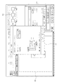
図1は、本発明の実施の形態1に係る画像処理システムの構成を示す模式図である。
(Embodiment 1)
FIG. 1 is a schematic diagram showing a configuration of an image processing system according to
図1に示すように、本実施の形態1に係る画像処理システムは、対象物(ワーク)6を移動させるマニピュレータ(ロボット)1、マニピュレータ1の動作を制御するロボットコントローラ2、画像処理装置3、及び撮像装置4で構成されている。マニピュレータ1の先端には、対象物6を把持又は解放することが可能なエンドエフェクタ5が設けられており、ロボットコントローラ2はエンドエフェクタ5の開閉動作も制御する。
As shown in FIG. 1, an image processing system according to the first embodiment includes a manipulator (robot) 1 that moves an object (workpiece) 6, a
撮像装置4は、例えばカラーCCDカメラであり、移動する対象物であるワーク6を撮像する。撮像された画像に基づいて、後述するキャリブレーションを実行することにより、実際のワーク6の位置座標(エンドエフェクタ5の移動位置の座標)と、画面に表示された画像上の位置座標とをリンクさせることができる。
The
マニピュレータ1は、3本のアームで構成されており、2本のアームが互いになす角度、及びアーム支点の回転により、エンドエフェクタ5を所望の位置へ移動させる。
The
図2は、本発明の実施の形態1に係る画像処理システムの画像処理装置3の構成例を示すブロック図である。本発明の実施の形態1に係る画像処理装置3は、少なくともCPU(中央演算装置)等で構成された制御部31、メモリ32、記憶装置33、入出力インタフェース34、表示インタフェース35、通信インタフェース36及び上述したハードウェアを接続する内部バス37で構成されている。
FIG. 2 is a block diagram illustrating a configuration example of the
制御部31は、内部バス37を介して画像処理装置3の上述したようなハードウェア各部と接続されており、上述したハードウェア各部の動作を制御するとともに、記憶装置33に記憶されているコンピュータプログラムに従って、種々のソフトウェア的機能を実行する。メモリ32は、SRAM、SDRAM等の揮発性メモリで構成され、コンピュータプログラムの実行時にロードモジュールが展開され、コンピュータプログラムの実行時に発生する一時的なデータ等を記憶する。
The
記憶装置33は、内蔵される固定型記憶装置(ハードディスク)、SRAM等の揮発性メモリ、ROM等の不揮発性メモリ等で構成されている。記憶装置33に記憶されているコンピュータプログラムは、プログラム及びデータ等の情報を記録したDVD、CD−ROM等の可搬型記録媒体からダウンロード、あるいは通信インタフェース36を介してダウンロードされ、実行時には記憶装置33からメモリ32へ展開して実行される。
The
通信インタフェース(通信装置)36は内部バス37に接続されており、インターネット、LAN、WAN等の外部のネットワークに接続されることにより、外部のコンピュータ等とデータ送受信を行うことが可能となっている。
A communication interface (communication device) 36 is connected to an
入出力インタフェース34は、キーボード38、マウス39等のデータ入力媒体と接続され、データの入力を受け付ける。また、表示インタフェース35は、CRTモニタ、LCD等の表示装置40と接続され、所定の画像を表示する。
The input /
従来、マニピュレータ1の動作制御は、ロボットコントローラ2に記憶されているシーケンシャルな動作制御プログラムにより行われていた。その場合、マニピュレータ1のエンドエフェクタ5の実際の位置座標と、画像処理装置3に表示されている画像上の位置座標との間でキャリブレーションを実行する必要がある。
Conventionally, the operation control of the
キャリブレーションは、複数の位置座標について、マニピュレータ1のエンドエフェクタ5の実際の位置座標と、画像処理装置3に表示されている画像上の位置座標との間の変換式を算出する。座標変換の方法は、特に限定されるものではなく、例えばアフィン変換で変換する。
The calibration calculates a conversion formula between the actual position coordinates of the

(式1)に示すように、マニピュレータ1のエンドエフェクタ5の実際の位置座標(x’、y’)と、画像処理装置3に表示されている画像上の位置座標(x、y)とに基づいて、6つの自由度を有する変換式の係数a、b、c、d、e、fを求める。対応する位置座標が6つを超える場合には、最小二乗法を用いれば良い。
As shown in (Expression 1), the actual position coordinates (x ′, y ′) of the
図3は、従来のキャリブレーションの処理手順を示すフローチャートである。図3に示すように、ロボットコントローラ2は、マニピュレータ1に撮像対象となるマークを付与したワーク6を、キャリブレーションターゲットとして把持させた状態で、エンドエフェクタ5をキャリブレーション位置へと移動させる(ステップS301)。
FIG. 3 is a flowchart showing a conventional calibration processing procedure. As shown in FIG. 3, the
ロボットコントローラ2は、移動したエンドエフェクタ5の位置座標(x’、y’)を取得して(ステップS302)、計測命令及び取得した位置座標(x’、y’)を画像処理装置3へ送信する(ステップS303)。画像処理装置3は、ロボットコントローラ2から計測命令及び取得した位置座標(x’、y’)を受信し(ステップS304)、エンドエフェクタ5の動作領域を撮像する(ステップS305)。
The
画像処理装置3は、エンドエフェクタ5の動作領域の画像を表示し、表示されている画像上の位置座標(x、y)を検出する(ステップS306)。ロボットコントローラ2は、キャリブレーション用のすべての位置座標(x’、y’)について画像上の位置座標(x、y)を検出したか否かを判断する(ステップS307)。ロボットコントローラ2が、まだすべての位置座標(x’、y’)について画像上の位置座標(x、y)を検出していないと判断した場合(ステップS307:NO)、ロボットコントローラ2は、次の移動命令を発行し(ステップS308)、処理をステップS301へ戻して、上述した処理を繰り返す。
The
ロボットコントローラ2が、すべての位置座標(x’、y’)について画像上の位置座標(x、y)を検出したと判断した場合(ステップS307:YES)、画像処理装置3は、(式1)に従って変換式を算出する(ステップS309)。具体的には、6つの係数a、b、c、d、e、fを求める。
When the
しかし、従来のキャリブレーションでは、マニピュレータ1の種別ごとに固有のシーケンシャルな制御プログラムが必要となる。したがって、機種ごとに個別の制御プログラムによりキャリブレーションを実行しなければならない。そこで、画像処理装置3において主たるキャリブレーションを実行する。
However, the conventional calibration requires a unique sequential control program for each type of
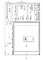
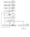
図4は、本発明の実施の形態1に係る画像処理システムのキャリブレーションの処理手順を示すフローチャートである。図4に示すように、画像処理装置3は、マニピュレータ1に撮像対象となるマークを付与したワーク6を、キャリブレーションターゲットとして把持させた状態で、キャリブレーションの開始位置を設定する(ステップS401)。図5は、本発明の実施の形態1に係る画像処理装置3の開始位置設定画面の例示図である。
FIG. 4 is a flowchart showing a calibration processing procedure of the image processing system according to the first embodiment of the present invention. As shown in FIG. 4, the
図5に示すように、撮像された対象物6の画像は画像表示領域55に表示されている。キャリブレーションの実行ボタンのうち、開始位置設定ボタン51が選択されると、開始位置設定画面56がポップアップ表示され、開始位置を設定する。この場合、ジョグ操作ボタン57を選択することで、マニピュレータ1のエンドエフェクタ5を所定の位置に移動させることができる。したがって、移動先を確認しながらキャリブレーションの開始位置を設定することができる。
As shown in FIG. 5, the captured image of the
なお、移動パターンを設定する前に、検出ツールを設定することができる。図6は、本発明の実施の形態1に係る画像処理装置3の検出ツール設定画面の例示図である。
Note that the detection tool can be set before setting the movement pattern. FIG. 6 is an exemplary view of a detection tool setting screen of the
図6に示すように、キャリブレーションの実行ボタンのうち、検出ツール設定ボタン52が選択されると、検出ツール選択領域61が表示される。ユーザは、画像表示領域55に表示されている画像を見ながら、検出ツール選択領域61において検出ツールを選択する。図6の例では、輪郭検出ツールを選択している。これ以外に、例えば濃淡検出ツールを選択しても良い。
As shown in FIG. 6, when the detection
図4に戻って、画像処理装置3は、マニピュレータ1のエンドエフェクタ5の移動パターンを設定する(ステップS402)。図7及び図8は、本発明の実施の形態1に係る画像処理装置3の移動パターンの設定画面の例示図である。
Returning to FIG. 4, the
図7に示すように、キャリブレーションの実行ボタンのうち、キャリブレーションボタン53が選択されると、移動パターン設定画面71がポップアップ表示される。ここで、移動パターンの設定ボタン72を選択すると、図8に示すように、詳細設定画面73がポップアップ表示される。
As shown in FIG. 7, when the
詳細設定画面73では、キャリブレーション実行時の検出パターンを設定する。例えば、3×3の9個、5×5の25個等の設定を受け付ける。所定の移動距離を設定することで、詳細設定画面73の下部に表示されるような移動パターンが設定される。
On the
図4に戻って、画像処理装置3は移動命令をロボットコントローラ2へ送信する(ステップS403)。ロボットコントローラ2は、移動命令を受信して(ステップS404)、移動命令をマニピュレータ1の種別に応じて解釈する(ステップS405)。すなわち、マニピュレータ1を稼働させることが可能な機械語のロードモジュールに翻訳する。
Returning to FIG. 4, the
ロボットコントローラ2は、エンドエフェクタ5を移動命令で指定されている位置へと移動させ(ステップS406)。ロボットコントローラ2は、エンドエフェクタ5の移動先の位置座標(x’、y’)を取得して(ステップS407)、取得した位置座標(x’、y’)を画像処理装置3へ送信する(ステップS408)。
The
画像処理装置3は、ロボットコントローラ2から、取得した位置座標(x’、y’)を受信し(ステップS409)、エンドエフェクタ5の動作領域を撮像する(ステップS410)。画像処理装置3は、動作領域の画像を表示し、表示されている画像上の位置座標(x、y)を検出する(ステップS411)。
The
なお、表示されている画像上のどの位置の位置座標(x、y)を検出するかは、設定されている検出ツールを用いて画像中から検出する。例えば検出ツールとして、輪郭検出ツールが選択されている場合、検出される輪郭領域を指定する必要がある。 Note that the position coordinates (x, y) on the displayed image to be detected are detected from the image using a set detection tool. For example, when the contour detection tool is selected as the detection tool, it is necessary to specify the contour region to be detected.
図9及び図10は、本発明の実施の形態1に係る画像処理装置3の輪郭検出ツールを用いる場合の検出条件設定画面の例示図である。図9に示すように、ツール表示領域91において、選択されている「輪郭検出ツール」が表示されている。そして、パターン編集領域92において、輪郭パターンの形状を設定する。図9の例では矩形領域に設定されている。
9 and 10 are exemplary diagrams of a detection condition setting screen when the contour detection tool of the
そして、画像表示領域55に表示されている対象物において、マウス等でドラッグ操作をしながら、輪郭パターンを検出する検出領域93を設定する。図9の例では、対象物を囲むように設定しているが、特にこのような設定に限定されるものではない。
Then, a
検出領域93が設定されると、図10に示すように、検出条件設定画面94において、検出条件を設定する。検出条件としては、例えば対象物の傾きの許容範囲である「角度範囲」、検出する個数を示す「検出個数」、どの程度まで類似していれば検出するかを示す「相関値下限」等を設定する。
When the
また、検出ツールとして、濃淡検出ツールを選択しても良い。濃淡検出ツールが選択されている場合であっても、検出する領域を設定する必要がある。 Moreover, you may select the light / dark detection tool as a detection tool. Even when the shading detection tool is selected, it is necessary to set the detection area.
図11及び図12は、本発明の実施の形態1に係る画像処理装置3の濃淡検出ツールを用いる場合の検出条件設定画面の例示図である。図11に示すように、ツール表示領域91において、選択されている「濃淡検出ツール」が表示されている。そして、パターン編集領域92において、輪郭パターンの形状を設定する。図11の例では矩形領域に設定されている。
FIG. 11 and FIG. 12 are examples of detection condition setting screens when the shading detection tool of the
そして、画像表示領域55に表示されている対象物において、マウス等でドラッグ操作をしながら、輪郭パターンを検出する検出領域93を設定する。図11の例では、対象物を囲むように設定しているが、特にこのような設定に限定されるものではない。
Then, a
検出領域93が設定されると、図12に示すように、検出条件設定領域121において、検出条件を設定する。検出条件としては、例えば対象物の傾きの許容範囲である「角度範囲」、検出する個数を示す「検出個数」、どの程度まで類似していれば検出するかを示す「相関値下限」等の他、検出感度(サーチ感度)あるいは検出精度(サーチ精度)についても設定することができる。形状が同じであっても、濃淡差等に違いが生じている場合が想定されるからである。
When the
図4に戻って、画像処理装置3は、キャリブレーション用のすべての位置座標(x’、y’)について画像上の位置座標(x、y)を検出したか否かを判断する(ステップS412)。画像処理装置3が、まだすべての位置座標(x’、y’)について画像上の位置座標(x、y)を検出していないと判断した場合(ステップS412:NO)、画像処理装置3は、次の移動命令を発行し(ステップS413)、処理をステップS403へ戻して、上述した処理を繰り返す。
Returning to FIG. 4, the
画像処理装置3が、すべての位置座標(x’、y’)について画像上の位置座標(x、y)を検出したと判断した場合(ステップS412:YES)、画像処理装置3は、(式1)に従って変換式を算出する(ステップS414)。具体的には、6つの係数a、b、c、d、e、fを求める。
When the
なお、キャリブレ−ションとして二次元のアフィン変換を用いる例について説明しているが、もちろん三次元のアフィン変換を用いても良い。 In addition, although the example which uses a two-dimensional affine transformation as a calibration is demonstrated, of course, you may use a three-dimensional affine transformation.
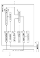
図13は、本発明の実施の形態1に係る画像処理装置3の機能ブロック図である。画像処理装置3の移動座標取得部301は、移動命令に応じて移動したエンドエフェクタ5の各位置座標である第一の座標値(x’、y’)を取得する。
FIG. 13 is a functional block diagram of the
なお、移動座標取得部301において取得する第一の座標値(x’、y’)は、画像処理装置3からの移動命令に応じてエンドエフェクタ5が移動した各位置において、ロボットコントローラ2から取得した座標値としているが、画像処理装置3で表示されている画像上で指定されたマニピュレータ(ロボット)1の移動目標座標をそのまま第一の座標値としても良い。
The first coordinate values (x ′, y ′) acquired by the movement coordinate
撮像制御部302は、エンドエフェク5が移動した各移動先にて対象物を撮像するよう撮像装置4の動作を制御する。これにより、ロボットコントローラ2から取得した移動先のエンドエフェクタ5の位置座標である第一の座標値(x’、y’)に対応する領域を撮像するよう制御することで、取得した第一の座標値(x’、y’)との間でキャリブレーションを実行することができる。
The
画像検出部303は、各移動先にて撮像された対象物6の画像に基づいて対象物の位置座標である第二の座標値(x、y)を検出する。キャリブレーション実行部304は、取得した複数の第一の座標値(x’、y’)と、検出した複数の第二の座標値(x、y)とに基づいて、両座標間の変換規則を算出する。例えば二次元のキャリブレーションを実行する場合、上述した(式1)に座標値を代入して、係数a、b、c、d、e、fを求める。
The
キャリブレーションを実行することにより、ロボットコントローラ2から取得した移動先のエンドエフェクタ5の位置座標である第一の座標値(x’、y’)を指定して移動命令を送信するだけでなく、各移動先にて撮像された対象物の6の画像に基づいて検出された第二の座標値(x、y)から第一の座標値(x’、y’)を算出することができ、移動命令を送信することができる。つまり、画像処理装置3からロボットコントローラ2に対して動作の指令を送信することができるようになる。
By executing the calibration, not only the first coordinate value (x ′, y ′) that is the position coordinate of the
動作設定受付部305は、少なくとも第一の座標値(x’、y’)へエンドエフェクタ5を移動させる動作又は第二の座標値(x、y)へエンドエフェクタ5を移動させる動作(具体的にはキャリブレーション結果を用いて第一の座標値へ変換した座標値へ移動させる動作)を含む複数の動作の中から、ロボットコントローラ2に実行させる複数の動作の選択を受け付け、選択を受け付けた複数の動作の実行順序の設定を受け付ける。
The operation
具体的には、まず移動先の位置データを記憶する。図14は、本発明の実施の形態1に係る画像処理装置3の位置データ登録画面の例示図である。まず、マニピュレータ(ロボット)1のエンドエフェクタ5を撮像位置へ移動させる。移動命令は、画像処理装置3からロボットコントローラ2へ送信する。
Specifically, first, position data of the movement destination is stored. FIG. 14 is an exemplary view of a position data registration screen of the
エンドエフェクタ5の位置データは、第一の座標値(x’、y’)としてロボットコントローラ2から移動座標取得部301により取得する。図14(a)には、取得した第一の座標値が表示されている。
The position data of the
そして、登録ボタン141をマウス等でクリック操作することにより、取得した第一の座標値を識別子、例えば「POS001」とともに記憶する。第一の座標値が1つでも記憶されている場合、図14(b)に示すように、移動ボタン142が使用可能な状態となる。位置データを選択して移動ボタン142をマウス等でクリック操作することにより、移動命令を送信することができる。
Then, by clicking the
図15は、本発明の実施の形態1に係る画像処理装置3の位置データ選択画面の例示図である。図15に示すように、位置データ選択領域151に、既に記憶されている位置データ候補が表示されている。ユーザは、この中から1つの位置データを選択すれば良い。
FIG. 15 is an exemplary view of a position data selection screen of the
また、表示されている画像上で位置の指定を受け付けても良い。図16は、本発明の実施の形態1に係る画像処理装置3の位置データ選択画面の他の例示図である。図16の例では、位置データ選択領域151が存在しない。あくまでも撮像された画像が表示されている画像表示領域55において、現在の位置を「十」印161で表示している。ユーザは、マウス等のクリック操作により、移動先の位置「+」印162を指定すれば良い。
Further, the designation of the position on the displayed image may be accepted. FIG. 16 is another exemplary view of the position data selection screen of the
すなわち、位置データ選択画面は、図13の移動先選択部309として機能する。移動先選択部309は、エンドエフェクタ5の複数の第一の座標値を取得し、複数の第一の座標値の中からエンドエフェクタ5の移動先として一の第一の座標値の選択を受け付ける。
That is, the position data selection screen functions as the movement
図13に戻って、動作設定受付部305は、ロボットコントローラ2から受信する、撮像装置4で対象物6の撮像を開始するタイミングを示す撮像トリガごとに、少なくとも動作の種類及び動作順序を含む動作条件の設定も受け付ける。設定を受け付けた撮像トリガごとの動作条件をロボットコントローラ2から受信したタイミングで、撮像装置4によりワーク6を撮像する。撮像トリガとしては、特にどのような情報でなければならないという限定はない。少なくとも撮像装置4に撮像を開始するタイミングを知らせる信号であれば足りる。
Returning to FIG. 13, the operation
動作設定受付部305は、エンドエフェクタ5に対する待機指令の設定を受け付けても良い。撮像までの待機時間を設定を受け付けることで、動作直後の振動を抑制し、撮像時のエンドエフェクタ5の位置を安定させることができる。これにより、撮像装置4をエンドエフェクタ5に取り付けた状態での検出、あるいはワーク6をエンドエフェクタ5に把持させた状態での位置検出の精度を高くすることが可能となる。
The operation
プログラム生成部306は、動作設定受付部305で選択を受け付けた複数の動作それぞれに対応する動作プログラムを、設定を受け付けた実行順序に従って生成する。具体的には、設定を受け付けた実行順序に従って、選択を受け付けた複数の動作に対応する各動作プログラムを、編集可能なテキストデータとして生成する。
The
自動的に生成するとともに、ユーザの意向により自由にカスタマイズできるように、プログラム生成部306は、例えばロボットコントローラ2による動作のうち、少なくとも第一の座標値又は第2の座標値へエンドエフェクタ5を移動させる動作、撮像トリガを送信する動作を含む、ロボットコントローラ2に実行させる一連の複数の動作について動作プログラムを生成すれば良い。もちろん、ロボットコントローラ2とのデータ通信を確立する動作プログラムを生成しても良い。
The
また、マニピュレータ(ロボット)1の種別によって動作プログラムのフォーマットが異なるので、プログラム生成部306は、動作設定受付部305で選択を受け付けた複数の動作それぞれに対応する動作プログラムを、設定を受け付けた実行順序に従って生成する。
In addition, since the format of the operation program differs depending on the type of the manipulator (robot) 1, the
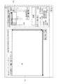
図17は、本発明の実施の形態1に係る画像処理装置3のプログラム生成画面の例示図である。図17において、シーケンス選択領域171では、動作プログラムに組み込む動作の候補である動作リストが表示されている。ユーザは、表示されている動作リストの中から、生成されるプログラムで実行したい動作を選択する。
FIG. 17 is a view showing an example of a program generation screen of the
また、生成されるプログラムで制御する対象となるマニピュレータ(ロボット)1の製造元であるメーカを、メーカ選択領域172において選択する(ロボット選択受付部307)。生成される動作プログラムは、メーカごとに仕様が異なるからである。ロボット選択受付部307は、ロボットの種別の選択を受け付け、プログラム生成部306は、選択を受け付けたマニピュレータ1の種別ごとに規定されたフォーマットに従って動作プログラムを生成する。
In addition, a manufacturer that is the manufacturer of the manipulator (robot) 1 to be controlled by the generated program is selected in the manufacturer selection area 172 (robot selection reception unit 307). This is because the generated operation program has different specifications for each manufacturer. The robot
ここで、動作リストの中から選択することができるのは、エンドエフェクタ5の移動、撮像トリガの送信等の動作(以下、汎用動作)のみである。選択することができない動作としては、例えばエンドエフェクタ5の詳細な動作(ピッキング、リリース等)、他に接続されている外部機器の動作等(以下、特殊動作)である。動作プログラムの一部として、まず汎用動作に相当する部分のみ編集可能な形式で自動生成する。そして、最終的には、ユーザが特殊動作に相当する部分を編集することにより、動作プログラムを完成することができる。
Here, only operations such as movement of the
すべての設定が完了した状態で、プログラム出力ボタン173をマウス等によりクリック操作することにより、ロボットコントローラ2の動作プログラムが生成される。図18は、本発明の実施の形態1に係るロボットコントローラ2の動作プログラムの例示図である。
When all settings are completed, an operation program for the
図18に示すように、ソースコード181は、画像処理装置3とのデータ通信を確立する命令である。ソースコード182は、撮像装置4を退避させる命令である。ソースコード183は、画像処理装置3に対する座標値取得命令である。
As illustrated in FIG. 18, the
ソースコード184は、画像処理装置3から座標値を受信する命令である。ソースコード185は、実際のマニピュレータ1の位置座標に変換する命令である。
The
ソースコード186は、マニピュレータ1のエンドエフェクタ5を移動の最終位置へ移動させる命令である。ソースコード187は、コメント欄であり、ユーザ自身がソースコードを記述することで、よりユーザニーズに応じた動作プログラムを生成することができる。ソースコード188は、画像処理装置3とのデータ通信を解除する命令である。
The
図13に戻って、移動命令送信部308は、第一の座標値又は第2の座標値へエンドエフェクタ5を移動させる移動命令をロボットコントローラ2へ送信する。なお、図16に示すように移動先の位置情報の指定を受け付けた場合には、画像上で指定を受け付けた位置にエンドエフェクタ5を移動させる移動命令をロボットコントローラ2へ送信する。
Returning to FIG. 13, the movement
また、ロボットコントローラ2は、動作を制御するマニピュレータ(ロボット)1の種別に応じて、移動命令を変換する必要がある。図19は、本発明の実施の形態1に係るロボットコントローラ2の機能ブロック図である。
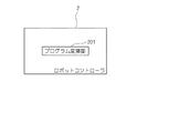
Further, the
図19に示すように、ロボットコントローラ2は、プログラム変換部201を備えている。プログラム変換部201は、マニピュレータ(ロボット)1の種別ごとに提供されており、移動命令をマニピュレータ1の種別に応じたエンドエフェクタ5への移動命令に変換する。これにより、使用するマニピュレータ1の種別に応じた変換プログラムをロボットコントローラ2にインストールすることができ、マニピュレータ1の種別に応じたエンドエフェクタ5の移動命令に変換することができる。
As illustrated in FIG. 19, the
図20は、本発明の実施の形態1に係るロボットコントローラ2の変換プログラムの処理手順を示すフローチャートである。図20に示すように、ロボットコントローラ2は、画像処理装置3とデータ通信を確立し(ステップS2001)、移動命令を受信したか否かを判断する(ステップS2002)。
FIG. 20 is a flowchart showing the processing procedure of the conversion program of the
ロボットコントローラ2が、受信していないと判断した場合(ステップS2002:NO)、ロボットコントローラ2は、受信待ち状態となる。ロボットコントローラ2が、受信したと判断した場合(ステップS2002:YES)、ロボットコントローラ2は、最初の移動命令を解釈する(ステップS2003)。
When the
ロボットコントローラ2は、解釈した移動命令の内容に沿って移動命令を切り替えて、マニピュレータ1のエンドエフェクタ5を移動させる(ステップS2004)。ロボットコントローラ2は、すべての移動命令を解釈したか否かを判断する(ステップS2005)。
The
ロボットコントローラ2が、まだ解釈していない移動命令があると判断した場合(ステップS2005:NO)、ロボットコントローラ2は、次の移動命令を解釈して(ステップS2006)、処理をステップS2004へ戻して上述した処理を繰り返す。ロボットコントローラ2が、すべての移動命令を解釈したと判断した場合(ステップS2005:YES)、ロボットコントローラ2は、処理を終了する。
When the
図21は、本発明の実施の形態1に係る画像処理システムのシステム構築手順を示すフローチャートである。図21に示すように、画像処理装置3は、図4に示すキャリブレーションを実行し(ステップS2101)、位置座標の変換式を求める。
FIG. 21 is a flowchart showing a system construction procedure of the image processing system according to the first embodiment of the present invention. As shown in FIG. 21, the
画像処理装置3は、ワーク6を検出する検出ツールの選択を受け付ける(ステップS2102)。具体的には、図6に示す検出ツール設定画面の検出ツール設定領域61において検出ツールを選択する。
The
画像処理装置3は、動作プログラムを作成する(ステップS2103)。画像処理装置3は、試運転で動作を確認したサンプルプログラムの詳細を編集して(ステップS2104)、運用段階へ移行させる(ステップS2105)。
The
図22は、本発明の実施の形態1に係る画像処理装置3の動作プログラム作成の処理手順を示すフローチャートである。図22に示すように、画像処理装置3は、移動先の位置データを一又は複数記憶する(ステップS2201)。
FIG. 22 is a flowchart showing a processing procedure for creating an operation program of the
画像処理装置3は、動作の実行順序である動作シーケンスを記憶し(ステップS2202)、マニピュレータ(ロボット)1のメーカの選択を受け付ける(ステップS2203)。動作シーケンスは、例えば図17に示すプログラム生成画面のシーケンス選択領域171において、実行したい処理(移動)の順番にプルダウンメニューの中から選択する。また、メーカの選択は、例えば図17に示すプログラム生成画面のメーカ選択領域172において選択する。
The
画像処理装置3は、試運転を行って(ステップS2204)、その時点のサンプルプログラムを出力する(ステップS2205)。つまり、従来はプログラムが完成していないと動作確認をすることができなかったのに対して、基本動作が正しいか否かを試運転で確認しながら詳細を詰めることができる点に本願の特徴がある。
The
ユーザは、マニピュレータ(ロボット)1の動作が、所望の動作であるか否かを判断して(ステップS2206)、ユーザが所望の動作ではないと判断した場合(ステップS2206:NO)、画像処理装置3は、サンプルプログラムの編集を受け付けて(ステップS2207)、処理をステップS2204へ戻して、上述した処理を繰り返す。ユーザが所望の動作であると判断した場合(ステップS2206:YES)、画像処理装置3は、サンプルプログラムの送信依頼を受け付けて、サンプルプログラムのソースコードをテキストデータとして出力する(ステップS2208)。
When the user determines whether the operation of the manipulator (robot) 1 is a desired operation (step S2206) and determines that the operation is not a desired operation (step S2206: NO), the
マニピュレータ(ロボット)1の試運転時の動作は特に限定されるものではない。図23は、本発明の実施の形態1に係る画像処理システムにおける試運転時の動作を説明するための模式図である。 The operation at the time of trial operation of the manipulator (robot) 1 is not particularly limited. FIG. 23 is a schematic diagram for explaining an operation during a test run in the image processing system according to the first embodiment of the present invention.
本実施の形態1に係る画像処理システムは、まず図23(a)に示すように、ワーク6を撮像できるよう、マニピュレータ1のエンドエフェクタ5をワーク6が載置されている位置とは異なる位置「POS000」へ移動させる。この状態で、図23(b)に示すように、撮像トリガに応じてワーク6を撮像し、最後に図23(c)に示すように、ワーク6を把持するべく、マニピュレータ1のエンドエフェクタ5をワーク6が載置されている位置(検出位置)へと移動させる。
In the image processing system according to the first embodiment, first, as shown in FIG. 23A, the
斯かる動作をマニピュレータ(ロボット)1にさせるべく、ロボットコントローラ2で実行される動作プログラムは、プログラム生成画面から容易に生成することができる。図24は、本発明の実施の形態1に係る画像処理装置3のプログラム生成画面の例示図である。
In order to make the manipulator (robot) 1 perform such an operation, the operation program executed by the
図24において、シーケンス選択領域241では、生成されるプログラムで実行したい処理(動作)をプルダウンメニューの中から選択する。また、生成されるプログラムで制御する対象となるマニピュレータ(ロボット)1の製造元であるメーカを、メーカ選択領域242において選択する。生成されるプログラムは、メーカごとに仕様が異なるからである。
In FIG. 24, in a
図24の例では、事前に登録されている位置座標(図24では識別子として「POS000」)へ移動し、撮像開始のタイミングを示す撮像トリガを発行して、ワーク6を把持する位置まで移動する動作を制御するプログラムを生成するよう指定している。全ての指定が完了した時点で、プログラム出力ボタン243をマウス等によりクリック操作することで、ロボットコントローラ2の動作プログラムが生成される。
In the example of FIG. 24, it moves to a position coordinate registered in advance (“POS000” as an identifier in FIG. 24), issues an imaging trigger indicating the timing of imaging start, and moves to a position where the
図25は、本発明の実施の形態1に係る画像処理システムの試運転時の処理手順を示すフローチャートである。図25に示すように、画像処理装置3は、所定位置(図24の例では「POS000」)への移動命令をロボットコントローラ2へ送信する(ステップS2501)。
FIG. 25 is a flowchart showing a processing procedure during a test run of the image processing system according to the first embodiment of the present invention. As shown in FIG. 25, the
ロボットコントローラ2は、画像処理装置3からの移動命令を受信し(ステップS2502)、移動命令をマニピュレータ1の種別に応じて解釈する(ステップS2503)。すなわち、マニピュレータ1を稼働させることが可能な機械語のロードモジュールに翻訳する。
The
ロボットコントローラ2は、エンドエフェクタ5を移動命令で指定されている位置(図24の例では「POS000」)へと移動させ(ステップS2504)、撮像命令を画像処理装置3へ送信する(ステップS2505)。
The
画像処理装置3は、撮像命令を受信し(ステップS2506)、エンドエフェクタ5の動作領域を撮像する(ステップS2507)。画像処理装置3は、エンドエフェクタ5の動作領域の画像を表示し、表示されている画像上のワーク6の位置座標(x、y)を検出し(ステップS2508)、キャリブレーションにより求めてある変換式を用いて位置座標(x’、y’)へ変換する(ステップS2509)。
The
画像処理装置3は、位置座標(x’、y’)への移動命令をロボットコントローラ2へ送信する(ステップS2510)。ロボットコントローラ2は、移動命令を受信して(ステップS2511)、変換された位置座標(x’、y’)へエンドエフェクタ5を移動する(ステップS2512)
The
なお、試運転の実行に備えて、2つの実行モードを準備しておくことが好ましい。例えば1つは「ティーチングモード」、もう1つは「自動運転モード」である。 In addition, it is preferable to prepare two execution modes in preparation for execution of a test run. For example, one is “teaching mode” and the other is “automatic operation mode”.
「ティーチングモード」では、ユーザが動作を確認しながらサンプルプログラムを更新するためのモードである。したがって、ユーザは、マニピュレータ1の近傍で作業をしている可能性が高いので、安全を確保するために低速動作に限定し、何らかのスイッチを意識的に押下げ続けている状態でないと動作しないよう設定されている。
In the “teaching mode”, the user updates the sample program while confirming the operation. Therefore, since the user is likely to work in the vicinity of the
また、「自動運転モード」では、「ティーチングモード」のような動作制限は存在しない。その代わり、ユーザの安全を確保するために、例えば所定の範囲内に人が存在することを人感センサが検知した場合には動作しない等の対策を施す必要はある。なお、キャリブレーションの実行時には、ユーザが近傍に存在する可能性が高いので、「ティーチングモード」の時だけ動作できる、といったロボットコントローラ2における制限機能を付与することが好ましい。
Further, in the “automatic operation mode”, there is no operation restriction like the “teaching mode”. Instead, in order to ensure the safety of the user, it is necessary to take measures such as not operating when the human sensor detects that a person is present within a predetermined range. Note that when performing calibration, it is highly possible that the user is in the vicinity. Therefore, it is preferable to provide a restriction function in the
以上のように本実施の形態1によれば、画像処理装置3からロボットコントローラ2に対してマニピュレータ(ロボット)1の動作を制御する動作プログラムを画像処理装置3内で生成することができるので、マニピュレータ1の種別ごとに異なる機械語を理解していない作業者(ユーザ)であっても、マニピュレータ1の動作を高い精度で制御することができる動作プログラムを作成することが可能となる。したがって、すべての動作プログラムが完成する都度、動作を確認する煩雑な手順が不要となるので、システムとして早期に立ち上げることが可能となる。
As described above, according to the first embodiment, an operation program for controlling the operation of the manipulator (robot) 1 from the
(実施の形態2)
本発明の実施の形態2に係る画像処理システムの構成、画像処理装置3の構成は、実施の形態1と同様であることから、同一の機能を有する構成要素については同一の符号を付することにより詳細な説明は省略する。本実施の形態2は、設定条件を切り替えて動作を切り替えることが可能な動作プログラムを生成する点で、実施の形態1とは相違する。
(Embodiment 2)
Since the configuration of the image processing system according to the second embodiment of the present invention and the configuration of the
実施の形態2では、ワーク6のピッキングの実行を例に挙げて説明する。図26は、本発明の実施の形態2に係る画像処理システムにおけるピッキングの実行を説明するための模式図である。図26に示すように、本実施の形態2に係る画像処理システムは、ワーク6をピックアップ位置261からプレース位置262へと移動させる。具体的には、撮像装置4でピックアップ位置261のワーク6を撮像しながら、ワーク6をマニピュレータ1のエンドエフェクタ5で把持し、プレース位置262まで移動してからワーク6を解放する。
In the second embodiment, execution of picking of the
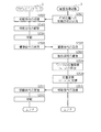
図27は、本発明の実施の形態2に係る画像処理システムのピッキングの処理手順を示すフローチャートである。図27に示すように、ロボットコントローラ2は、マニピュレータ1のエンドエフェクタ5により撮像対象であるワーク6を撮像装置4で撮像することができない事態を回避するために、マニピュレータ1のエンドエフェクタ5を撮像領域内から移動する(ステップS2701)。
FIG. 27 is a flowchart showing a picking processing procedure of the image processing system according to the second embodiment of the present invention. As shown in FIG. 27, the
ロボットコントローラ2は、撮像命令を画像処理装置3へ送信する(ステップS2702)。画像処理装置3は、撮像命令を受信して(ステップS2703)、ワーク6を撮像する(ステップS2704)。画像処理装置3は、ワーク6の画像を表示し、表示されている画像上のワーク6の位置座標(x、y)を検出して(ステップS2705)、キャリブレーションにより求めてある変換式を用いて位置座標(x’、y’)へ変換する(ステップS2706)。画像処理装置3は、変換された位置座標(x’、y’)をロボットコントローラ2へ送信する(ステップS2707)。
The
ロボットコントローラ2は、位置座標(x’、y’)を受信し(ステップS2708)、ワーク6を把持するピックアップ位置261へエンドエフェクタ5を移動させる(ステップS2709)。ロボットコントローラ2は、エンドエフェクタ5にワーク6を把持させる(ステップS2710)。
The
ロボットコントローラ2は、ワーク6を把持しながらエンドエフェクタ5をプレース位置262へ移動させ(ステップS2711)、ワーク6を解放させる(ステップS2712)。なお、破線で囲まれている範囲の処理、すなわちステップS2710、ステップS2712以外の処理は、マニピュレータ1の動作を制御する動作プログラムを自動生成することができる。
The
ワーク6のエンドエフェクタ5で把持した位置がずれているため、撮像位置を補正する必要がある場合も生じうる。図28は、本発明の実施の形態2に係る画像処理システムにおける撮像位置を補正する場合のピッキングの実行を説明するための模式図である。
Since the position gripped by the
図28に示すように、本実施の形態2に係る画像処理システムは、ワーク6をピックアップ位置261からプレース位置262へと移動させる。図26とは異なり、ワーク6をマニピュレータ1のエンドエフェクタ5で把持し、プレース位置262まで移動する間の状態を撮像装置4で撮像する。つまり、マニピュレータ1のエンドエフェクタ5で把持された時点でワーク6の存在位置が機械的にずれるので、そのずれを補正する。
As shown in FIG. 28, the image processing system according to the second embodiment moves the
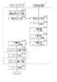
図29は、本発明の実施の形態2に係る画像処理システムの撮像位置を補正する場合のピッキングの処理手順を示すフローチャートである。図29に示すように、ロボットコントローラ2は、マニピュレータ1のエンドエフェクタ5をピックアップ位置261へ移動する(ステップS2901)。
FIG. 29 is a flowchart showing a picking processing procedure when the imaging position of the image processing system according to the second embodiment of the present invention is corrected. As shown in FIG. 29, the
ロボットコントローラ2は、ワーク6を把持し(ステップS2902)、撮像装置4によりマニピュレータ1のエンドエフェクタ5で把持されたワーク6を撮像する位置へと移動する(ステップS2903)。ロボットコントローラ2は、撮像命令を画像処理装置3へ送信する(ステップS2904)
The
画像処理装置3は、撮像命令を受信して(ステップS2905)、ワーク6を撮像する(ステップS2906)。画像処理装置3は、ワーク6の画像を表示し、表示されている画像上のワーク6の位置座標(x、y)を検出して(ステップS2907)、キャリブレーションにより求めてある変換式を用いて位置座標(x’、y’)へ変換する(ステップS2908)。画像処理装置3は、変換された位置座標(x’、y’)をロボットコントローラ2へ送信する(ステップS2909)。
The
ロボットコントローラ2は、位置座標(x’、y’)を受信し(ステップS2910)、移動命令で指定した位置座標へエンドエフェクタ5を移動させる(ステップS2911)。ロボットコントローラ2は、位置座標(x’、y’)が移動命令で指定した位置座標と一定範囲内に収束しているか否かを判断する(ステップS2912)。
The
ロボットコントローラ2が、位置座標(x’、y’)が移動命令で指定した位置座標と一定範囲内に収束していないと判断した場合(ステップS2912:NO)、ロボットコントローラ2は、処理をステップS2904へ戻して、上述した処理を繰り返す。ロボットコントローラ2が、位置座標(x’、y’)が移動命令で指定した位置座標と一定範囲内に収束したと判断した場合(ステップS2912:YES)、ロボットコントローラ2は、ワーク6を把持しながらエンドエフェクタ5をプレース位置262へ移動させ(ステップS2913)、ワーク6を解放させる(ステップS2914)。なお、破線で囲まれている範囲の処理、すなわちステップS2902、ステップS2912、ステップS2914以外の処理は、マニピュレータ1の動作を制御する動作プログラムを自動生成することができる。
When the
ピッキングの実行についても、条件が変更された場合には、生成される動作プログラムが変動する。例えば撮像位置が相違する、画像から検出する位置が相違する、マニピュレータ1のメーカが相違する等、条件の相違に対応して動作プログラムを切り替えることが好ましい。
As for the execution of picking, when the condition is changed, the generated operation program varies. For example, it is preferable to switch the operation program in response to different conditions, such as different imaging positions, different positions detected from images, different manufacturers of the
図30は、本発明の実施の形態2に係る画像処理システムの異なる動作条件の設定例を示す条件設定画面の例示図である。まず図30(a)に示すように、「条件0」として、条件設定領域3001において撮像位置を「POS0」、画像から検出する位置を「A」と設定しており、メーカ設定領域3002において、マニピュレータ1のメーカを「メーカA」と設定している。一方、図30(b)に示すように、「条件1」として、条件設定領域3001において撮像位置を「POS1」、画像から検出する位置を「B」と設定しており、メーカ設定領域3002において、マニピュレータ1のメーカを「メーカA」と設定している。ここでは、同じメーカのマニピュレータ1に異なる動作をさせている。
FIG. 30 is an exemplary diagram of a condition setting screen showing an example of setting different operating conditions of the image processing system according to the second embodiment of the present invention. First, as shown in FIG. 30A, as “
図31は、本発明の実施の形態2に係る画像処理システムの異なる動作条件に切り替え可能な動作プログラムの例示図である。図31に示すように、ソースコード3100は、画像処理装置3とのデータ通信を確立する命令である。ソースコード3101は、Val0の値に応じて動作条件の切り替えを実行する命令である。
FIG. 31 is an exemplary diagram of an operation program that can be switched to different operation conditions of the image processing system according to the second embodiment of the present invention. As shown in FIG. 31, the
具体的には、Val0の値が‘0’である場合、条件0に基づくソースコード3102を実行し、Val0の値が‘1’である場合、条件1に基づくソースコード3103を実行することになる。なお、ソースコード3100は、自動的に生成しても良いし、ユーザが書き加えても良い。
Specifically, when the value of Val0 is “0”, the
図32は、本発明の実施の形態2に係る画像処理システムにおける動作条件の切り替えが必要となるピッキングの実行を説明するための模式図である。図32に示すように、本実施の形態2に係る画像処理システムは、ワーク6A又はワーク6Bをピックアップ位置261からプレース位置262へと移動させる。
FIG. 32 is a schematic diagram for explaining execution of picking that requires switching of operating conditions in the image processing system according to the second embodiment of the present invention. As shown in FIG. 32, the image processing system according to the second embodiment moves the
具体的には、撮像装置4でピックアップ位置261のワーク6A又はワーク6Bを撮像しながら、ワーク6A又はワーク6Bをマニピュレータ1のエンドエフェクタ5で把持し、プレース位置262まで移動してからワーク6A又はワーク6Bを解放する。同時に2つのワークを保持することはできないので、まずはワーク6Aを把持して移動する動作プログラムを、次にワーク6Bを把持して移動する動作プログラムを、それぞれ実行する。
Specifically, the
図33A及び図33Bは、本発明の実施の形態2に係る画像処理システムの動作条件の切り替えを含むピックアップの処理手順を示すフローチャートである。図33A及び図33Bに示すように、ロボットコントローラ2は、動作条件の切り替えについて、画像処理装置3で設定を受け付けた条件がどの条件であるかを判断する(ステップS3301)。ロボットコントローラ2が、条件‘0’へ切り替えの設定を受け付けていると判断した場合(ステップS3301:‘0’)、ロボットコントローラ2は、条件‘0’への切替命令を画像処理装置3へ送信する(ステップS3302)。
FIG. 33A and FIG. 33B are flowcharts showing the processing procedure of the pickup including switching of operating conditions of the image processing system according to the second embodiment of the present invention. As illustrated in FIGS. 33A and 33B, the
切替命令としては、本実施の形態2に示すように、個別に切替命令を送信しても良いし、後述する撮像命令(撮像トリガ)に含ませても良い。つまり、撮像装置4で対象物6の撮像を開始するタイミングを示す撮像トリガで条件を切り替えても良い。撮像トリガごとに、少なくとも動作の種類及び動作順序を含む動作条件の設定を受け付けているので、撮像トリガに応じて動作条件を切り替えることができ、動作に応じた適切なタイミングで対象物6を撮像して、表示されている画像上の対象物6の位置座標を検出することが可能となる。
As the switching command, as shown in the second embodiment, the switching command may be transmitted individually, or may be included in an imaging command (imaging trigger) described later. That is, the condition may be switched by an imaging trigger indicating the timing at which the
画像処理装置3は、切替命令を受信して(ステップS3303)、応答信号をロボットコントローラ2へ送信する(ステップS3304)。ロボットコントローラ2は、応答信号を受信して(ステップS3305)、位置POS0へマニピュレータ1のエンドエフェクタ5を移動させる(ステップS3306)。
The
ロボットコントローラ2は、撮像命令を画像処理装置3へ送信する(ステップS3307)。画像処理装置3は、撮像命令を受信して(ステップS3308)、ワーク6を撮像する(ステップS3309)。画像処理装置3は、ワーク6の画像を表示し、表示されている画像上のワーク6の位置座標(x、y)を検出して(ステップS3310)、キャリブレーションにより求めてある変換式を用いて位置座標(x’、y’)へ変換する(ステップS3311)。画像処理装置3は、変換された位置座標(x’、y’)をロボットコントローラ2へ送信する(ステップS3312)。
The
ロボットコントローラ2は、位置座標(x’、y’)を受信し(ステップS3313)、位置座標(x’、y’)で示されているワーク6を把持するピックアップ位置261へ、マニピュレータ1のエンドエフェクタ5を移動させる(ステップS3314)。ロボットコントローラ2は、エンドエフェクタ5にワーク6を把持させ(ステップS3315)、ワーク6を把持しながらエンドエフェクタ5をプレース位置262へ移動させて(ステップS3316)、ワーク6を解放させる(ステップS3317)。
The
ロボットコントローラ2が、条件‘1’へ切り替えの設定を受け付けていると判断した場合(ステップS3301:‘1’)、ロボットコントローラ2は、条件‘1’への切替命令を画像処理装置3へ送信する(ステップS3320)。
If the
画像処理装置3は、切替命令を受信して(ステップS3321)、応答信号をロボットコントローラ2へ送信する(ステップS3322)。ロボットコントローラ2は、応答信号を受信して(ステップS3323)、位置POS1へマニピュレータ1のエンドエフェクタ5を移動させる(ステップS3324)。
The
ロボットコントローラ2は、撮像命令を画像処理装置3へ送信する(ステップS3325)。画像処理装置3は、撮像命令を受信して(ステップS3326)、ワーク6を撮像する(ステップS3327)。画像処理装置3は、ワーク6の画像を表示し、表示されている画像上のワーク6の位置座標(x、y)を検出して(ステップS3328)、キャリブレーションにより求めてある変換式を用いて位置座標(x’、y’)へ変換する(ステップS3329)。画像処理装置3は、変換された位置座標(x’、y’)をロボットコントローラ2へ送信する(ステップS3330)。
The
ロボットコントローラ2は、位置座標(x’、y’)を受信し(ステップS3331)、位置座標(x’、y’)で示されているワーク6を把持するピックアップ位置261へ、マニピュレータ1のエンドエフェクタ5を移動させる(ステップS3332)。ロボットコントローラ2は、エンドエフェクタ5にワーク6を把持させ(ステップS3333)、ワーク6を把持しながらエンドエフェクタ5をプレース位置262へ移動させて(ステップS3334)、ワーク6を解放させる(ステップS3335)。なお、破線で囲まれている範囲の処理、すなわちステップS3315、ステップS3317、ステップS3333、ステップS3335以外の処理は、マニピュレータ1の動作を制御する動作プログラムを自動生成することができる。
The
以上のように本実施の形態2によれば、画像処理装置3からロボットコントローラ2に対してマニピュレータ1のエンドエフェクタ5の動作を制御する移動命令、動作命令を送信することができるので、ユーザがマニピュレータ(ロボット)1の種別ごとに異なる機械語を理解する必要がなく、マニピュレータ1を試運転することにより正しく動作するか否かを確認することが可能となる。したがって、すべての動作プログラムが完成する都度、動作を確認する煩雑な手順が不要となるので、システムとして早期に立ち上げることが可能となる。
As described above, according to the second embodiment, since the
なお、本発明は上記実施例に限定されるものではなく、本発明の趣旨の範囲内であれば多種の変更、改良等が可能である。例えばロボットコントローラ2の代わりにモーションコントローラを用いることで、適用範囲を拡大することができる。
The present invention is not limited to the above-described embodiments, and various changes and improvements can be made within the scope of the present invention. For example, the application range can be expanded by using a motion controller instead of the
また、従来、ロボットコントローラ2で移動目標位置を取得する場合、画像処理装置3からは相対的な位置座標を受信していた。例えば、画像処理装置3では、移動することにより生ずる差分である、差分距離X(X方向の差分)、差分距離Y(Y方向の差分)及び差分角度(XY平面上での回転角度)θを画像から検出し、ロボットコントローラ2は、受信した差分距離X、差分距離Y及び差分角度θを基準位置に加算することにより、移動目標位置を特定していた。
Conventionally, when the movement target position is acquired by the
しかし、本実施の形態では、基準位置を含む座標系を画像処理装置3に記憶しておくことができる。したがって、ロボットコントローラ2に対して、差分距離X、差分距離Y及び差分角度θという相対的な位置座標ではなく、画像処理装置3内で算出した移動目標位置の座標値そのものを送信することができる。
However, in the present embodiment, a coordinate system including the reference position can be stored in the
これにより、マニピュレータ1のエンドエフェクタ5を移動させる場合に、ロボットコントローラ2側で基準座標を記憶しておく必要がない。したがって、画像処理装置3のみで移動目標位置の座標値を出力することができ、ワーク6を交換するときに、改めて新たなワーク6について基準座標を設定する必要もなく、操作が煩雑にならない。
Thus, when the
1 マニピュレータ(ロボット)
2 ロボットコントローラ
3 画像処理装置
4 撮像装置
5 エンドエフェクタ
6 対象物(ワーク)
31 制御部
32 メモリ
33 記憶装置
36 通信インタフェース
1 Manipulator (robot)
2
31
Claims (22)
前記ロボットによる操作対象である対象物を撮像する撮像装置と
を有する画像処理装置であって、
前記ロボットのエンドエフェクタの移動先の各位置座標である第一の座標値を取得する移動座標取得手段と、
前記エンドエフェクタの各移動先にて対象物を撮像するよう前記撮像装置の動作を制御する撮像制御手段と、
各移動先にて撮像された対象物の画像に基づいて、対象物の位置座標である第二の座標値を検出する画像検出手段と、
少なくとも前記第一の座標値へ前記エンドエフェクタを移動させる動作又は前記第二の座標値へ前記エンドエフェクタを移動させる動作を含む複数の動作の中から、前記ロボットコントローラに実行させる複数の動作の選択を受け付け、選択を受け付けた複数の動作の実行順序の設定を受け付ける動作設定受付手段と、
該動作設定受付手段で選択を受け付けた複数の動作それぞれに対応する動作プログラムを、設定を受け付けた実行順序に従って生成するプログラム生成手段と
を備えることを特徴とする画像処理装置。 A communication device capable of data communication with a robot controller that controls the operation of the robot;
An image processing apparatus having an imaging device that images an object that is an operation target by the robot,
Movement coordinate acquisition means for acquiring a first coordinate value which is each position coordinate of the movement destination of the end effector of the robot;
Imaging control means for controlling the operation of the imaging apparatus so as to image a target object at each destination of the end effector;
Image detecting means for detecting a second coordinate value, which is a position coordinate of the object, based on the image of the object imaged at each destination;
Selection of a plurality of operations to be executed by the robot controller from among a plurality of operations including an operation of moving the end effector to at least the first coordinate value or an operation of moving the end effector to the second coordinate value And an operation setting accepting unit for accepting setting of an execution order of a plurality of operations for which selection has been accepted,
An image processing apparatus comprising: a program generation unit configured to generate an operation program corresponding to each of a plurality of operations whose selection is received by the operation setting reception unit according to an execution order in which the setting is received.
前記プログラム生成手段は、選択を受け付けた前記ロボットの種別ごとに規定されたフォーマットに従って前記動作プログラムを生成することを特徴とする請求項1乃至5のいずれか一項に記載の画像処理装置。 Robot selection receiving means for receiving selection of the robot type,
The image processing apparatus according to claim 1, wherein the program generation unit generates the operation program in accordance with a format defined for each type of the robot that has received a selection.
該ロボットコントローラとデータ通信することが可能に接続された通信装置、及び前記ロボットによる操作対象である対象物を撮像する撮像装置を含む画像処理装置とで構成される画像処理システムであって、
前記画像処理装置は、
前記ロボットのエンドエフェクタの移動先の各位置座標である第一の座標値を取得する移動座標取得手段と、
前記エンドエフェクタの各移動先にて対象物を撮像するよう前記撮像装置の動作を制御する撮像制御手段と、
各移動先にて撮像された対象物の画像に基づいて、対象物の位置座標である第二の座標値を検出する画像検出手段と、
少なくとも前記第一の座標値へ前記エンドエフェクタを移動させる動作又は前記第二の座標値へ前記エンドエフェクタを移動させる動作を含む複数の動作の中から、前記ロボットコントローラに実行させる複数の動作の選択を受け付け、選択を受け付けた複数の動作の実行順序の設定を受け付ける動作設定受付手段と、
該動作設定受付手段で選択を受け付けた複数の動作それぞれに対応する動作プログラムを、設定を受け付けた実行順序に従って生成するプログラム生成手段と
を備えることを特徴とする画像処理システム。 A robot controller that controls the operation of the robot;
An image processing system including a communication device connected to be able to perform data communication with the robot controller, and an image processing device including an imaging device that images an object that is an operation target by the robot,
The image processing apparatus includes:
Movement coordinate acquisition means for acquiring a first coordinate value which is each position coordinate of the movement destination of the end effector of the robot;
Imaging control means for controlling the operation of the imaging apparatus so as to image a target object at each destination of the end effector;
Image detecting means for detecting a second coordinate value, which is a position coordinate of the object, based on the image of the object imaged at each destination;
Selection of a plurality of operations to be executed by the robot controller from among a plurality of operations including an operation of moving the end effector to at least the first coordinate value or an operation of moving the end effector to the second coordinate value And an operation setting accepting unit for accepting setting of an execution order of a plurality of operations for which selection has been accepted,
An image processing system comprising: a program generation unit that generates an operation program corresponding to each of a plurality of operations whose selection is received by the operation setting reception unit according to an execution order in which the setting is received.
前記ロボットの種別の選択を受け付けるロボット選択受付手段を備え、
前記プログラム生成手段は、選択を受け付けた前記ロボットの種別ごとに規定されたフォーマットに従って前記動作プログラムを生成することを特徴とする請求項11乃至15のいずれか一項に記載の画像処理システム。 The image processing apparatus includes:
Robot selection receiving means for receiving selection of the robot type,
The image processing system according to claim 11, wherein the program generation unit generates the operation program according to a format defined for each type of the robot that has received a selection.
前記第一の座標値又は前記第2の座標値へ前記エンドエフェクタを移動させる移動命令を前記ロボットコントローラへ送信する移動命令送信手段を備えることを特徴とする請求項11乃至17のいずれか一項に記載の画像処理システム。 The image processing apparatus includes:
18. A movement command transmission unit that transmits a movement command for moving the end effector to the first coordinate value or the second coordinate value to the robot controller. The image processing system described in 1.
撮像された対象物が表示されている画像上で指定を受け付けた位置に前記エンドエフェクタを移動させる移動命令を前記ロボットコントローラへ送信する移動命令送信手段を備えることを特徴とする請求項11乃至17のいずれか一項に記載の画像処理システム。 The image processing apparatus includes:
18. A movement command transmitting means for transmitting a movement command for moving the end effector to a position where designation is received on an image on which an imaged target is displayed is provided to the robot controller. The image processing system according to any one of the above.
前記エンドエフェクタの複数の第一の座標値を取得し、複数の第一の座標値の中から前記エンドエフェクタの移動先として一の第一の座標値の選択を受け付ける移動先選択手段を備えることを特徴とする請求項11乃至19のいずれか一項に記載の画像処理システム。 The image processing apparatus includes:
A destination selection means for acquiring a plurality of first coordinate values of the end effector and receiving a selection of one first coordinate value as a destination of the end effector from among the plurality of first coordinate values; The image processing system according to claim 11, wherein:
該ロボットコントローラとデータ通信することが可能に接続された通信装置、及び前記ロボットによる操作対象である対象物を撮像する撮像装置を含む画像処理装置とで構成される画像処理システムで実行することが可能な画像処理方法であって、
前記画像処理装置は、
前記ロボットのエンドエフェクタの移動先の各位置座標である第一の座標値を取得する工程と、
前記エンドエフェクタの各移動先にて対象物を撮像するよう前記撮像装置の動作を制御する工程と、
各移動先にて撮像された対象物の画像に基づいて、対象物の位置座標である第二の座標値を検出する工程と、
少なくとも前記第一の座標値へ前記エンドエフェクタを移動させる動作又は前記第二の座標値へ前記エンドエフェクタを移動させる動作を含む複数の動作の中から、前記ロボットコントローラに実行させる複数の動作の選択を受け付け、選択を受け付けた複数の動作の実行順序の設定を受け付ける工程と、
選択を受け付けた複数の動作それぞれに対応する動作プログラムを、設定を受け付けた実行順序に従って生成する工程と
を含むことを特徴とする画像処理方法。 A robot controller that controls the operation of the robot;
An image processing system comprising: a communication device connected so as to be able to perform data communication with the robot controller; and an image processing device including an imaging device that images an object that is an operation target of the robot. A possible image processing method,
The image processing apparatus includes:
Obtaining a first coordinate value which is each position coordinate of the movement destination of the end effector of the robot;
Controlling the operation of the imaging device to image a target at each destination of the end effector;
Detecting a second coordinate value that is a position coordinate of the object based on an image of the object imaged at each destination; and
Selection of a plurality of operations to be executed by the robot controller from among a plurality of operations including an operation of moving the end effector to at least the first coordinate value or an operation of moving the end effector to the second coordinate value And accepting the setting of the execution order of a plurality of operations for which selection has been accepted, and
And a step of generating an operation program corresponding to each of the plurality of operations for which selection has been received in accordance with an execution order for which the setting has been received.
前記ロボットによる操作対象である対象物を撮像する撮像装置と
を有する画像処理装置で実行することが可能なコンピュータプログラムであって、
前記画像処理装置を、
前記ロボットのエンドエフェクタの移動先の各位置座標である第一の座標値を取得する移動座標取得手段、
前記エンドエフェクタの各移動先にて対象物を撮像するよう前記撮像装置の動作を制御する撮像制御手段、
各移動先にて撮像された対象物の画像に基づいて、対象物の位置座標である第二の座標値を検出する画像検出手段、
少なくとも前記第一の座標値へ前記エンドエフェクタを移動させる動作又は前記第二の座標値へ前記エンドエフェクタを移動させる動作を含む複数の動作の中から、前記ロボットコントローラに実行させる複数の動作の選択を受け付け、選択を受け付けた複数の動作の実行順序の設定を受け付ける動作設定受付手段、及び
該動作設定受付手段で選択を受け付けた複数の動作それぞれに対応する動作プログラムを、設定を受け付けた実行順序に従って生成するプログラム生成手段
として機能させることを特徴とするコンピュータプログラム。 A communication device capable of data communication with a robot controller that controls the operation of the robot;
A computer program that can be executed by an image processing device having an imaging device that images an object that is an operation target by the robot,
The image processing apparatus;
A movement coordinate acquisition means for acquiring a first coordinate value which is each position coordinate of the movement destination of the end effector of the robot;
An imaging control means for controlling the operation of the imaging apparatus so as to image a target object at each destination of the end effector;
Image detecting means for detecting a second coordinate value, which is a position coordinate of the object, based on an image of the object imaged at each destination;
Selection of a plurality of operations to be executed by the robot controller from among a plurality of operations including an operation of moving the end effector to at least the first coordinate value or an operation of moving the end effector to the second coordinate value The operation setting accepting means for accepting the setting of the execution order of the plurality of actions accepted for selection, and the operation order corresponding to each of the plurality of actions accepted for selection by the action setting accepting means for executing the setting. A computer program that functions as a program generation unit that generates a program according to the above.
Priority Applications (2)
| Application Number | Priority Date | Filing Date | Title |
|---|---|---|---|
| JP2014262241A JP6486678B2 (en) | 2014-12-25 | 2014-12-25 | Image processing apparatus, image processing system, image processing method, and computer program |
| US14/956,414 US10065320B2 (en) | 2014-12-25 | 2015-12-02 | Image processing apparatus, image processing system, image processing method, and computer program |
Applications Claiming Priority (1)
| Application Number | Priority Date | Filing Date | Title |
|---|---|---|---|
| JP2014262241A JP6486678B2 (en) | 2014-12-25 | 2014-12-25 | Image processing apparatus, image processing system, image processing method, and computer program |
Publications (2)
| Publication Number | Publication Date |
|---|---|
| JP2016120565A true JP2016120565A (en) | 2016-07-07 |
| JP6486678B2 JP6486678B2 (en) | 2019-03-20 |
Family
ID=56163182
Family Applications (1)
| Application Number | Title | Priority Date | Filing Date |
|---|---|---|---|
| JP2014262241A Active JP6486678B2 (en) | 2014-12-25 | 2014-12-25 | Image processing apparatus, image processing system, image processing method, and computer program |
Country Status (2)
| Country | Link |
|---|---|
| US (1) | US10065320B2 (en) |
| JP (1) | JP6486678B2 (en) |
Cited By (1)
| Publication number | Priority date | Publication date | Assignee | Title |
|---|---|---|---|---|
| JPWO2021085501A1 (en) * | 2019-10-28 | 2021-05-06 |
Families Citing this family (10)
| Publication number | Priority date | Publication date | Assignee | Title |
|---|---|---|---|---|
| JP6486679B2 (en) | 2014-12-25 | 2019-03-20 | 株式会社キーエンス | Image processing apparatus, image processing system, image processing method, and computer program |
| EP3189947A1 (en) * | 2016-01-07 | 2017-07-12 | Sick Ag | Method for configuring and operating a monitored automated workcell and configuration device |
| JP6497374B2 (en) | 2016-10-27 | 2019-04-10 | 株式会社安川電機 | Robot system, robot system control method, operation command generation device, and program |
| CN109407603B (en) * | 2017-08-16 | 2020-03-06 | 北京猎户星空科技有限公司 | Method and device for controlling mechanical arm to grab object |
| JP6810087B2 (en) * | 2018-03-29 | 2021-01-06 | ファナック株式会社 | Machine learning device, robot control device and robot vision system using machine learning device, and machine learning method |
| JP7069971B2 (en) * | 2018-03-30 | 2022-05-18 | セイコーエプソン株式会社 | Controls, robots, and robot systems |
| CN108858186B (en) * | 2018-05-30 | 2021-05-07 | 南昌大学 | Method for detecting, identifying and tracking infrared object by using trolley |
| CN109531575A (en) * | 2018-12-29 | 2019-03-29 | 深圳市哎哟不错机器人科研有限公司 | Robot based on Color control |
| CN110275532B (en) * | 2019-06-21 | 2020-12-15 | 珠海格力智能装备有限公司 | Robot control method and device and visual equipment control method and device |
| JP2022017739A (en) * | 2020-07-14 | 2022-01-26 | 株式会社キーエンス | Image processing apparatus |
Citations (18)
| Publication number | Priority date | Publication date | Assignee | Title |
|---|---|---|---|---|
| JPS60101609A (en) * | 1983-11-08 | 1985-06-05 | Matsushita Electric Ind Co Ltd | Robot controller |
| JPH03126102A (en) * | 1989-10-12 | 1991-05-29 | Sony Corp | Device and method for robot control |
| JPH0655476A (en) * | 1992-07-31 | 1994-03-01 | Citizen Watch Co Ltd | Robot instruction device |
| JPH06149345A (en) * | 1992-11-04 | 1994-05-27 | Yamatake Honeywell Co Ltd | Robot action teaching device |
| JPH06278064A (en) * | 1993-03-31 | 1994-10-04 | Citizen Watch Co Ltd | Method for converting coordinate of visual sensor |
| JPH07299793A (en) * | 1994-05-11 | 1995-11-14 | Toyota Autom Loom Works Ltd | Robot interference preventive controlling device |
| JPH08194518A (en) * | 1995-01-19 | 1996-07-30 | Komatsu Ltd | Work robot teaching device and work program composition device |
| JP2000135689A (en) * | 1998-10-30 | 2000-05-16 | Fanuc Ltd | Image processor for robot |
| JP2000153478A (en) * | 1998-09-03 | 2000-06-06 | Ricoh Elemex Corp | Robot system |
| JP2000181522A (en) * | 1998-12-11 | 2000-06-30 | Denso Corp | Robot system |
| US6681151B1 (en) * | 2000-12-15 | 2004-01-20 | Cognex Technology And Investment Corporation | System and method for servoing robots based upon workpieces with fiducial marks using machine vision |
| US6889118B2 (en) * | 2001-11-28 | 2005-05-03 | Evolution Robotics, Inc. | Hardware abstraction layer for a robot |
| JP2008068348A (en) * | 2006-09-13 | 2008-03-27 | National Institute Of Advanced Industrial & Technology | Robot work teaching system and work teaching method for robot |
| JP2008513867A (en) * | 2004-09-22 | 2008-05-01 | シーメンス アクチエンゲゼルシヤフト | Method for operating an automatic device and device for carrying out the method |
| JP2010092335A (en) * | 2008-10-09 | 2010-04-22 | Seiko Epson Corp | Operation sequence generation device, control method and program of operation sequence generation device |
| JP2012218119A (en) * | 2011-04-11 | 2012-11-12 | Canon Inc | Information processing apparatus, method for controlling the same, and program |
| US8355816B2 (en) * | 2008-03-10 | 2013-01-15 | Toyota Jidosha Kabushiki Kaisha | Action teaching system and action teaching method |
| US20140288710A1 (en) * | 2013-03-19 | 2014-09-25 | Kabushiki Kaisha Yaskawa Denki | Robot system and calibration method |
Family Cites Families (6)
| Publication number | Priority date | Publication date | Assignee | Title |
|---|---|---|---|---|
| JPH04134501A (en) | 1990-09-27 | 1992-05-08 | Toshiba Corp | Robot controller |
| JPH0991022A (en) | 1995-09-20 | 1997-04-04 | Yaskawa Electric Corp | Robot controller |
| US9195233B2 (en) * | 2006-02-27 | 2015-11-24 | Perrone Robotics, Inc. | General purpose robotics operating system |
| EP2981397B1 (en) * | 2013-04-05 | 2017-06-14 | ABB Schweiz AG | A robot system and method for calibration |
| JP5939213B2 (en) * | 2013-08-09 | 2016-06-22 | 株式会社安川電機 | Robot control apparatus and robot control method |
| JP6486679B2 (en) | 2014-12-25 | 2019-03-20 | 株式会社キーエンス | Image processing apparatus, image processing system, image processing method, and computer program |
-
2014
- 2014-12-25 JP JP2014262241A patent/JP6486678B2/en active Active
-
2015
- 2015-12-02 US US14/956,414 patent/US10065320B2/en not_active Expired - Fee Related
Patent Citations (18)
| Publication number | Priority date | Publication date | Assignee | Title |
|---|---|---|---|---|
| JPS60101609A (en) * | 1983-11-08 | 1985-06-05 | Matsushita Electric Ind Co Ltd | Robot controller |
| JPH03126102A (en) * | 1989-10-12 | 1991-05-29 | Sony Corp | Device and method for robot control |
| JPH0655476A (en) * | 1992-07-31 | 1994-03-01 | Citizen Watch Co Ltd | Robot instruction device |
| JPH06149345A (en) * | 1992-11-04 | 1994-05-27 | Yamatake Honeywell Co Ltd | Robot action teaching device |
| JPH06278064A (en) * | 1993-03-31 | 1994-10-04 | Citizen Watch Co Ltd | Method for converting coordinate of visual sensor |
| JPH07299793A (en) * | 1994-05-11 | 1995-11-14 | Toyota Autom Loom Works Ltd | Robot interference preventive controlling device |
| JPH08194518A (en) * | 1995-01-19 | 1996-07-30 | Komatsu Ltd | Work robot teaching device and work program composition device |
| JP2000153478A (en) * | 1998-09-03 | 2000-06-06 | Ricoh Elemex Corp | Robot system |
| JP2000135689A (en) * | 1998-10-30 | 2000-05-16 | Fanuc Ltd | Image processor for robot |
| JP2000181522A (en) * | 1998-12-11 | 2000-06-30 | Denso Corp | Robot system |
| US6681151B1 (en) * | 2000-12-15 | 2004-01-20 | Cognex Technology And Investment Corporation | System and method for servoing robots based upon workpieces with fiducial marks using machine vision |
| US6889118B2 (en) * | 2001-11-28 | 2005-05-03 | Evolution Robotics, Inc. | Hardware abstraction layer for a robot |
| JP2008513867A (en) * | 2004-09-22 | 2008-05-01 | シーメンス アクチエンゲゼルシヤフト | Method for operating an automatic device and device for carrying out the method |
| JP2008068348A (en) * | 2006-09-13 | 2008-03-27 | National Institute Of Advanced Industrial & Technology | Robot work teaching system and work teaching method for robot |
| US8355816B2 (en) * | 2008-03-10 | 2013-01-15 | Toyota Jidosha Kabushiki Kaisha | Action teaching system and action teaching method |
| JP2010092335A (en) * | 2008-10-09 | 2010-04-22 | Seiko Epson Corp | Operation sequence generation device, control method and program of operation sequence generation device |
| JP2012218119A (en) * | 2011-04-11 | 2012-11-12 | Canon Inc | Information processing apparatus, method for controlling the same, and program |
| US20140288710A1 (en) * | 2013-03-19 | 2014-09-25 | Kabushiki Kaisha Yaskawa Denki | Robot system and calibration method |
Cited By (3)
| Publication number | Priority date | Publication date | Assignee | Title |
|---|---|---|---|---|
| JPWO2021085501A1 (en) * | 2019-10-28 | 2021-05-06 | ||
| JP7408676B2 (en) | 2019-10-28 | 2024-01-05 | 京セラ株式会社 | Painting equipment and wiping method |
| US11919031B2 (en) | 2019-10-28 | 2024-03-05 | Kyocera Corporation | Coating device and wiping method |
Also Published As
| Publication number | Publication date |
|---|---|
| JP6486678B2 (en) | 2019-03-20 |
| US20160184997A1 (en) | 2016-06-30 |
| US10065320B2 (en) | 2018-09-04 |
Similar Documents
| Publication | Publication Date | Title |
|---|---|---|
| JP6486678B2 (en) | Image processing apparatus, image processing system, image processing method, and computer program | |
| JP6410388B2 (en) | Image processing apparatus, image processing system, image processing method, and computer program | |
| EP2608938B1 (en) | Vision-guided alignment system and method | |
| CN110154017B (en) | Conveyor tracking system and calibration method | |
| CN107871328B (en) | Machine vision system and calibration method implemented by machine vision system | |
| US10137574B2 (en) | Image processing apparatus, image processing system, image processing method, and computer program | |
| JP2017042859A (en) | Picking system, and processing device and method therefor and program | |
| JP5371927B2 (en) | Coordinate system calibration method and robot system | |
| CN105269578A (en) | Teaching apparatus and robot system | |
| TWI404609B (en) | Parameters adjustment method of robotic arm system and adjustment apparatus | |
| CN106182042B (en) | Equipment or object are selected by camera | |
| JP2016185572A (en) | Robot, robot control device, and robot system | |
| JP2017015396A (en) | Inspection method, inspection apparatus, processing apparatus, program, and recording medium | |
| JP2016031284A (en) | Control system, robot system, and control method | |
| CN109945780B (en) | Object inspection system and object inspection method | |
| JP2019168520A (en) | Information processing device, information processing method, program, and image measuring device | |
| US11590657B2 (en) | Image processing device, control method thereof, and program storage medium | |
| JP2019098409A (en) | Robot system and calibration method | |
| JP6926906B2 (en) | Robot system, control device and robot control method | |
| JP7427370B2 (en) | Imaging device, image processing device, image processing method, calibration method for imaging device, robot device, method for manufacturing articles using robot device, control program, and recording medium | |
| JP2013024773A (en) | Three-dimensional measuring method | |
| JP6772630B2 (en) | 3D measuring device and 3D object recognition method | |
| JP2020034484A (en) | Image inspection device | |
| JP6897398B2 (en) | 3D shape measuring device, robot system, and 3D shape measuring method | |
| JP2012168136A (en) | Image measurement device, auto-focus control method and auto-focus control program |
Legal Events
| Date | Code | Title | Description |
|---|---|---|---|
| A621 | Written request for application examination |
Free format text: JAPANESE INTERMEDIATE CODE: A621 Effective date: 20170831 |
|
| A977 | Report on retrieval |
Free format text: JAPANESE INTERMEDIATE CODE: A971007 Effective date: 20180807 |
|
| A131 | Notification of reasons for refusal |
Free format text: JAPANESE INTERMEDIATE CODE: A131 Effective date: 20180822 |
|
| A521 | Request for written amendment filed |
Free format text: JAPANESE INTERMEDIATE CODE: A523 Effective date: 20181017 |
|
| TRDD | Decision of grant or rejection written | ||
| A01 | Written decision to grant a patent or to grant a registration (utility model) |
Free format text: JAPANESE INTERMEDIATE CODE: A01 Effective date: 20190205 |
|
| A61 | First payment of annual fees (during grant procedure) |
Free format text: JAPANESE INTERMEDIATE CODE: A61 Effective date: 20190220 |
|
| R150 | Certificate of patent or registration of utility model |
Ref document number: 6486678 Country of ref document: JP Free format text: JAPANESE INTERMEDIATE CODE: R150 |
|
| R250 | Receipt of annual fees |
Free format text: JAPANESE INTERMEDIATE CODE: R250 |