JP2016118439A - Position detection device - Google Patents
Position detection device Download PDFInfo
- Publication number
- JP2016118439A JP2016118439A JP2014257481A JP2014257481A JP2016118439A JP 2016118439 A JP2016118439 A JP 2016118439A JP 2014257481 A JP2014257481 A JP 2014257481A JP 2014257481 A JP2014257481 A JP 2014257481A JP 2016118439 A JP2016118439 A JP 2016118439A
- Authority
- JP
- Japan
- Prior art keywords
- component
- calculation means
- amplitude ratio
- signals
- output
- Prior art date
- Legal status (The legal status is an assumption and is not a legal conclusion. Google has not performed a legal analysis and makes no representation as to the accuracy of the status listed.)
- Pending
Links
Images

Landscapes
- Transmission And Conversion Of Sensor Element Output (AREA)
Abstract
Description
本発明は、測定変位に対応して正弦波状に変化するとともに互いに90度位相が異なる2つの信号を出力する位置センサからの出力信号を位置情報に変換する位置検出装置に関する。 The present invention relates to a position detection device that converts an output signal from a position sensor that outputs two signals that change in a sinusoidal shape corresponding to a measured displacement and that are 90 degrees out of phase with each other into position information.
測定変位に対応して正弦波状に変化し、互いに90度位相が異なる2つの信号を出力する位置センサからの出力信号に含まれる2つの信号の振幅比・位相差成分を、前記2つの信号の自乗和の平方根を演算する半径演算手段を用いて求め、オフセット成分を自動的に除去し、高精度な位置情報に変換する位置検出装置が、特許文献1に開示されている。図2は特許文献1から引用した図であり、本発明に関して必要性がない装置等に関しては省略している。 The amplitude ratio / phase difference component of the two signals included in the output signal from the position sensor that outputs two signals that change in a sinusoidal shape corresponding to the measured displacement and that are 90 degrees out of phase with each other is obtained. Patent Document 1 discloses a position detection device that uses a radius calculation means for calculating the square root of the sum of squares, automatically removes an offset component, and converts it into highly accurate position information. FIG. 2 is a diagram quoted from Patent Document 1 and omits devices and the like that are not necessary for the present invention.
図2のロータ1は、外周部に波長λ=10度のピッチで1回転内に36個の凹凸を有する磁性体からできており、回転軸に固定されている。そして回転軸が回転するとロータ外周部の凹凸によるリラクタンス変化により、2種類の検出コイル2と3では、回転変位θ/36の余弦波アナログ信号ACと正弦波アナログ信号ASが発生する。これらの信号は、それぞれAD変換器4,5により、デジタル信号DC,DSに変換される。
The rotor 1 in FIG. 2 is made of a magnetic material having 36 irregularities in one rotation at a pitch of a wavelength λ = 10 degrees on the outer peripheral portion, and is fixed to a rotating shaft. When the rotating shaft rotates, the two types of
電源投入時、記憶器6と7には、位置検出装置製造時に測定された信号DC,DSに対する振幅比・位相差成分が記憶されている。乗算器8は記憶器6からの位相差成分PJと信号DCを乗算する。減算器9は乗算器8の出力信号と信号DSを減算し、信号DSに含まれる信号DCに対する位相差成分を除去する。乗算器10は記憶器7からの振幅比成分BJと減算器9から出力される位相差成分除去後の信号DSを乗算し、信号DSに含まれる信号DCに対する振幅比成分を除去する。その結果、乗算器10からは信号DSに含まれる信号DCに対する振幅比・位相差成分を除去した信号DSCが出力される。
When the power is turned on, the
内挿演算器12で、信号DC,DSCは2変数を入力とする逆正接演算が行われ、回転軸の1/36回転内の回転量を示す位置信号IPに変換される。また、信号DC,DSCは、半径演算器11により、式1の計算が行われ、信号DC,DSCの自乗和の平方根であるリサージュ円の半径量RDが出力される。なお、SQRTは平方根、^2は2乗を表す。
RD=SQRT(DC^2+DSC^2) ・・・(式1)
In the
RD = SQRT (DC ^ 2 + DSC ^ 2) (Formula 1)
なお、オフセットや位相差や振幅比等の内挿精度を悪化させる成分があった場合の半径量の変化について、表計算ツール等で数値解析を行うと、悪化させる成分の量と同じか、少なくとも1/2程度の変化が得られることが判明している。また、2つの信号の一方にオフセット誤差があると、半径量はλの波長で余弦波状に変化し、他方にオフセット誤差があると、半径量はλの波長で正弦波状に変化することが判明している。また、2つの信号に振幅差があると、半径量はλ/2の波長で余弦波状に変化することが判明している。また、2つの信号に位相差があると、半径量はλ/2の波長で正弦波状に変化することが判明している。その他、2つの信号の一方に2次高調波歪みがあると、半径量はλとλ/3の波長を持つ2つの同振幅の正弦波状に変化し、他方に2次高調波歪みがあると、半径量はλとλ/3の波長を持つ2つの同振幅の余弦波状に変化することが判明している。また、波長λのピッチで変化する2つの信号の変化量に比べ、半径量の変化は極めて変動が小さいことは明らかである。以上から、特許文献1に開示の技術は、変動の小さな半径量をもとに、オフセットや位相差や振幅比等の内挿精度を悪化させる成分を定量的に求めるものである。 Regarding the change in radius when there is a component that deteriorates the interpolation accuracy such as offset, phase difference, amplitude ratio, etc., if numerical analysis is performed with a spreadsheet tool etc., it is the same as the amount of the component that deteriorates, or at least It has been found that a change of about ½ can be obtained. Also, if one of the two signals has an offset error, the radius amount changes in a cosine wave shape at the wavelength of λ, and if the other has an offset error, the radius amount changes in a sine wave shape at the wavelength of λ. doing. It has also been found that if there is an amplitude difference between the two signals, the radius amount changes in a cosine wave shape at a wavelength of λ / 2. Further, it has been found that if there is a phase difference between the two signals, the radius amount changes sinusoidally at a wavelength of λ / 2. In addition, if there is a second-order harmonic distortion in one of the two signals, the radius will change to two sinusoidal waves of the same amplitude having wavelengths of λ and λ / 3, and the second harmonic distortion will be in the other It has been found that the radius varies into two cosine waves of the same amplitude having wavelengths of λ and λ / 3. In addition, it is clear that the change in the radius amount is very small compared to the change amount of the two signals that change at the pitch of the wavelength λ. From the above, the technique disclosed in Patent Document 1 quantitatively obtains a component that deteriorates the interpolation accuracy such as offset, phase difference, amplitude ratio, and the like based on a radius amount with small fluctuation.
フーリエ解析器(FFT)13では、回転位置がλ変化するごとに、内挿演算器12が出力した内挿値IPと、λ/2n(nは3以上の整数)の位置変化ごとの半径量RDに相当する値に基づき、フーリエ解析が行われる。
In the Fourier analyzer (FFT) 13, every time the rotational position changes by λ, the interpolation value IP output from the
演算器14では、FFT13が演算した半径量RDの波長λ/2の正弦成分である信号S2と、平均半径である信号RDAに対して、式2の計算が行われ、信号DPが出力される。
DP=2*S2/RDA ・・・(式2)
In the
DP = 2 * S2 / RDA (Formula 2)
減算器16では、記憶器6が記憶する信号DSの位相差成分を除去するための信号PJから、演算器14が出力した信号DPが減算される。減算器16が減算した信号は、FFT13からの記憶指令信号SETにより、記憶器6に記憶され、信号DSの位相差修正値として使用される。
In the
以上の構成により、波長λの回転変化だけで、信号DSの信号DCに対する位相差が90度に対してどれだけずれているか検出し、信号DSから位相差成分を除去することが可能である。 With the above configuration, it is possible to detect how much the phase difference of the signal DS with respect to the signal DC is shifted from 90 degrees by only the rotation change of the wavelength λ, and to remove the phase difference component from the signal DS.
演算器15では、FFT13が演算した半径量RDの波長λ/2の余弦成分である信号C2と、平均半径である信号RDAに対して、式3の計算が行われ、信号DBが出力される。
DB=(RDA+C2)/(RDA−C2) ・・・(式3)
In the
DB = (RDA + C2) / (RDA-C2) (Formula 3)
乗算器17では、記憶器7が記憶する信号DSの振幅比成分を除去するための信号BJと演算器15が出力した信号DBとが乗算される。乗算器17が乗算した信号は、FFT13からの記憶指令信号SETにより、記憶器7に記憶され、信号DSの振幅比修正値として使用される。
In the
以上の構成により、波長λの回転変化だけで、信号DSの信号DCに対する振幅比が1に対して異なる量を高精度に同定し、信号DSから除去することが可能である。 With the above configuration, it is possible to accurately identify and remove from the signal DS an amount in which the amplitude ratio of the signal DS to the signal DC is different from 1, only by the rotational change of the wavelength λ.
特許文献1に記載されている半径量RDより、振幅比・位相差成分を演算する方法では、フーリエ解析を行うために波長λピッチ内で2のn乗分の1の位置変化ごとの半径量RDに相当する値を算出しなければならない。しかし、ADサンプル周期あたり2のn乗分のλ以上位置が変化する速度ではフーリエ解析を行うことが出来ないため、振幅比・位相差成分を抽出することが出来ないという問題がある。
In the method of calculating the amplitude ratio / phase difference component from the radius amount RD described in Patent Document 1, in order to perform Fourier analysis, the radius amount for each position change of 1 /
本発明の位置検出装置は、測定変位に応じた位置情報を出力する位置検出装置であって、正弦波状に変化する90度位相の異なる2つの信号を出力する位置センサと、前記位置センサからの2つの出力信号の振幅比成分を除去する振幅比成分除去手段と、前記振幅比成分除去後の2つの信号を位置情報に変換する内挿演算手段と、前記位置センサからの2つの信号の自乗和の平方根を演算する半径演算手段と、前記半径演算手段の出力の変動成分と前記内挿演算手段からの位置情報を元にした2倍の周波数の余弦波とを其々乗算する相関演算手段と、前記相関演算手段の出力値のDC成分を抽出するDC成分抽出手段と、を備え、前記振幅比成分除去手段は、前記DC成分抽出手段の出力値に基づいて、前記振幅比成分を除去する、ことを特徴とする。 The position detection device of the present invention is a position detection device that outputs position information corresponding to a measured displacement, a position sensor that outputs two signals that are 90 degrees out of phase that change sinusoidally, and Amplitude ratio component removing means for removing the amplitude ratio component of the two output signals, an interpolation calculating means for converting the two signals after removal of the amplitude ratio component into position information, and the square of the two signals from the position sensor Radius calculating means for calculating the square root of the sum, and correlation calculating means for multiplying the fluctuation component of the output of the radius calculating means and a cosine wave having a double frequency based on position information from the interpolation calculating means, respectively. And DC component extraction means for extracting the DC component of the output value of the correlation calculation means, wherein the amplitude ratio component removal means removes the amplitude ratio component based on the output value of the DC component extraction means Special To.
本発明の位置検出装置は、測定変位に応じた位置情報を出力する位置検出装置であって、正弦波状に変化する90度位相の異なる2つの信号を出力する位置センサと、前記位置センサからの2つの出力信号の位相差成分を除去する位相差成分除去手段と、前記位相差成分除去後の2つの信号を位置情報に変換する内挿演算手段と、前記位置センサからの2つの信号の自乗和の平方根を演算する半径演算手段と、前記半径演算手段の出力の変動成分と前記内挿演算手段からの位置情報を元にした2倍の周波数の正弦波とを其々乗算する相関演算手段と、前記相関演算手段の出力値のDC成分を抽出するDC成分抽出手段と、を備え、前記位相差成分除去手段は、前記DC成分抽出手段の出力値に基づいて、前記位相差成分を除去する、ことを特徴とする。 The position detection device of the present invention is a position detection device that outputs position information corresponding to a measured displacement, a position sensor that outputs two signals that are 90 degrees out of phase that change sinusoidally, and Phase difference component removal means for removing the phase difference component of the two output signals, interpolation calculation means for converting the two signals after the phase difference component removal into position information, and the square of the two signals from the position sensor Radius calculation means for calculating the square root of the sum, and correlation calculation means for multiplying the fluctuation component of the output of the radius calculation means and a sine wave having a double frequency based on the position information from the interpolation calculation means, respectively. And DC component extracting means for extracting a DC component of the output value of the correlation calculating means, wherein the phase difference component removing means removes the phase difference component based on the output value of the DC component extracting means. Special To.
好適な態様では、前記DC成分抽出手段は、前記相関演算手段の出力を入力とする低域通過フィルタから成り、前記位置検出装置は、さらに、前記内挿演算手段からの位置情報を微分演算することで速度信号に変換する速度変換手段と、前記速度信号の値に基づいて設定される前記振幅比成分を記憶する振幅比記憶手段、を備えることを特徴とする。 In a preferred aspect, the DC component extraction means comprises a low-pass filter that receives the output of the correlation calculation means, and the position detection device further performs differential calculation of position information from the interpolation calculation means. In this manner, the apparatus includes a speed conversion unit that converts the signal into a speed signal, and an amplitude ratio storage unit that stores the amplitude ratio component set based on the value of the speed signal.
好適な態様では、前記DC成分抽出手段は、前記相関演算手段の出力を入力とする低域通過フィルタから成り、前記位置検出装置は、さらに、前記内挿演算手段からの位置情報を微分演算することで速度信号に変換する速度変換手段と、前記速度信号の値に基づいて設定される前記位相差成分を記憶する位相差記憶手段、を備えることを特徴とする。 In a preferred aspect, the DC component extraction means comprises a low-pass filter that receives the output of the correlation calculation means, and the position detection device further performs differential calculation of position information from the interpolation calculation means. And a phase difference storage unit for storing the phase difference component set based on the value of the speed signal.
他の好適な態様では、振幅比成分除去における前記相関演算手段は、前記半径演算手段の出力値のDC成分を出力する低域通過フィルタを有し、前記半径演算手段の出力値からDC成分を除去することにより、前記半径演算手段の出力の変動成分を入力とする、ことを特徴とする。 In another preferred aspect, the correlation calculation means in amplitude ratio component removal has a low-pass filter that outputs a DC component of the output value of the radius calculation means, and the DC component is output from the output value of the radius calculation means. By removing, the fluctuation component of the output of the radius calculation means is input.
他の好適な態様では、位相差成分除去における前記相関演算手段は、前記半径演算手段の出力値のDC成分を出力する低域通過フィルタを有し、前記半径演算手段の出力値からDC成分を除去することにより、前記半径演算手段の出力の変動成分を入力とする、ことを特徴とする。 In another preferred aspect, the correlation calculation means in phase difference component removal has a low-pass filter that outputs a DC component of the output value of the radius calculation means, and the DC component is output from the output value of the radius calculation means. By removing, the fluctuation component of the output of the radius calculation means is input.
本発明によれば、フーリエ変換を用いずとも、半径演算手段の出力と位置センサの2つの信号の相関演算により、振幅比・位相差成分に相当する成分を抽出できる。このため、特許文献1と同様に振幅比・位相差成分を高精度に同定することが可能である。また、AD変換器のサンプル周期あたり2のn乗分のλ以上位置が変化する回転速度の場合でも高精度に振幅比・位相差を同定することが可能である。したがって、高速回転でも振幅比・位相差の経時変化を正確に同定し、かつ精度悪化成分を除去し、内挿精度を大幅に向上させることが可能である。つまり、位置検出装置の高精度化と高速化を両立させることができる。 According to the present invention, a component corresponding to the amplitude ratio / phase difference component can be extracted by the correlation calculation of the output of the radius calculation means and the two signals of the position sensor without using the Fourier transform. For this reason, it is possible to identify the amplitude ratio / phase difference component with high accuracy as in Patent Document 1. Further, it is possible to identify the amplitude ratio and the phase difference with high accuracy even in the case of a rotational speed at which the position changes by λ of 2 n powers per sample period of the AD converter. Accordingly, it is possible to accurately identify the change over time in the amplitude ratio / phase difference even at high speed rotation, remove the accuracy deterioration component, and greatly improve the interpolation accuracy. That is, it is possible to achieve both high accuracy and high speed of the position detection device.
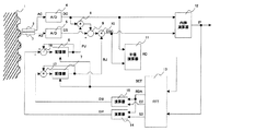
以下、図1に基づいて本発明の実施形態を説明する。なお、図1に示した構成要件のうち、図2と同様の機能を有するものは図2と同一の符号を付し、重複する説明を省略する。 Hereinafter, an embodiment of the present invention will be described with reference to FIG. 1 having the same functions as those in FIG. 2 are denoted by the same reference numerals as those in FIG. 2, and redundant descriptions are omitted.
半径演算器11から出力される半径量RDは低域通過フィルタ18に入力され、半径量RDのDC成分である信号RDDCが出力される。そして半径RDから信号RDDCが減算器19により減算され、半径RDの変動成分である信号RDACが出力される。2倍角正弦波テーブル20は、内挿演算器12より出力される1/36回転内の位置信号IPを元に、回転変位θ/36の2倍の周波数の正弦波信号2STを出力する。2倍角余弦波テーブル21は、内挿演算器12より出力される1/36回転内の位置信号IPを元に、回転変位θ/36の2倍の周波数の余弦波信号2CTを出力する。乗算器22は信号RDACと2倍角正弦波信号2STを相関演算し、信号RDA2Sを出力する。乗算器23は信号RDACと2倍角余弦波信号2CTを相関演算し、信号RDA2Cを出力する。DC成分抽出手段である低域通過フィルタ24,25に信号RDA2S,RDA2Cが入力され、信号RDA2S,RDA2CのDC成分R2SDC,R2CDCが出力される。
The radius amount RD output from the
演算器26は、式4に示される演算を行い、信号DSに含まれる、信号DCに対する位相差変位信号DPAを出力する。
DPA=R2SDC*4/RDD ・・・(式4)
The
DPA = R2SDC * 4 / RDD (Formula 4)
演算器27は、式5に示される演算を行い、信号DSに含まれる、信号DCに対する振幅比変位信号DBAを出力する。
DBA=(RDD+R2CDC*2)/(RDD−R2CDC*2)/RDD ・・・(式5)
The
DBA = (RDD + R2CDC * 2) / (RDD-R2CDC * 2) / RDD (Formula 5)
減算器16は、記憶器6が記憶する信号DSの位相差成分を除去するための信号PJから、演算器26が出力した信号DPAを減算し、減算信号PJDFを出力する。この減算信号PJDFは位相差変位分を含んだ位相差成分となる。
The
低域通過フィルタ18,24,25のカットオフ周波数よりも低い周波数で回転する場合、低域通過フィルタ18,24,25はDC成分を抽出できないため、低速回転では、位相差変位分を含んだ位相差信号PJDFの記憶器6への設定を止める必要がある。内挿演算器12が出力した内挿値IPを微分演算することにより、速度変換器28は速度信号VELを出力する。速度信号VELは記憶器30に記憶されている設定速度と比較器29にて比較され、速度信号VELが設定速度よりも大きい速度の場合、比較器29は記憶指令信号SETを出力する。記憶器6は記憶指令信号SETが入力された時、減算器16が出力する位相差変位分を含んだ位相差信号PJDFを記憶し、信号DSの位相差修正値として使用される。したがって、低域通過フィルタ18,24,25のカットオフ周波数より十分高い回転速度の場合のみ、位相差成分である信号PJが更新される。
When rotating at a frequency lower than the cut-off frequency of the low-
乗算器17は、記憶器7が記憶する信号DSの振幅比を除去するための信号BJから、演算器27が出力した信号DBAを乗算し、乗算信号BJDFを出力する。この乗算信号BJDFは振幅比変位分を含んだ振幅比成分となる。
The
記憶器7は、記憶指令信号SETが入力されたとき、乗算器17が出力する振幅比変位分を含んだ振幅比信号BJDFを記憶し、信号DSの振幅比修正値として使用される。したがって、低域通過フィルタ18,24,25のカットオフ周波数より十分高い回転速度の場合のみ、振幅比成分である信号BJが更新される。
The storage device 7 stores the amplitude ratio signal BJDF including the amplitude ratio displacement output from the
1 ロータ、2,3 検出コイル、4,5 AD変換器、6,7,30 記憶器、8,
10,17,22,23 乗算器、9,16,19 減算器、11 半径演算器、12 内挿演算器、13 フーリエ解析器、14,15,26,27 演算器、18,24,25 低域通過フィルタ、20 2倍角正弦波テーブル、21 2倍角余弦波テーブル、28 速度変換器、29 比較器。
1 rotor, 2, 3 detection coil, 4, 5 AD converter, 6, 7, 30 memory, 8,
10, 17, 22, 23 Multiplier, 9, 16, 19 Subtractor, 11 Radius calculator, 12 Interpolator, 13 Fourier analyzer, 14, 15, 26, 27 Calculator, 18, 24, 25 Low Band pass filter, 20 double angle sine wave table, 21 double angle cosine wave table, 28 speed converter, 29 comparator.
Claims (6)
正弦波状に変化する90度位相の異なる2つの信号を出力する位置センサと、
前記位置センサからの2つの出力信号の振幅比成分を除去する振幅比成分除去手段と、
前記振幅比成分除去後の2つの信号を位置情報に変換する内挿演算手段と、
前記位置センサからの2つの信号の自乗和の平方根を演算する半径演算手段と、
前記半径演算手段の出力の変動成分と前記内挿演算手段からの位置情報を元にした2倍の周波数の余弦波とを其々乗算する相関演算手段と、
前記相関演算手段の出力値のDC成分を抽出するDC成分抽出手段と、
を備え、
前記振幅比成分除去手段は、前記DC成分抽出手段の出力値に基づいて、前記振幅比成分を除去する、
ことを特徴とする位置検出装置。 A position detection device that outputs position information according to measurement displacement,
A position sensor that outputs two signals that are 90 degrees out of phase that change sinusoidally;
Amplitude ratio component removing means for removing amplitude ratio components of two output signals from the position sensor;
Interpolation operation means for converting the two signals after the amplitude ratio component removal into position information;
Radius calculating means for calculating the square root of the sum of squares of two signals from the position sensor;
Correlation calculation means for multiplying a fluctuation component of the output of the radius calculation means and a cosine wave having a double frequency based on position information from the interpolation calculation means,
DC component extraction means for extracting the DC component of the output value of the correlation calculation means;
With
The amplitude ratio component removing unit removes the amplitude ratio component based on an output value of the DC component extracting unit;
A position detecting device characterized by that.
正弦波状に変化する90度位相の異なる2つの信号を出力する位置センサと、
前記位置センサからの2つの出力信号の位相差成分を除去する位相差成分除去手段と、
前記位相差成分除去後の2つの信号を位置情報に変換する内挿演算手段と、
前記位置センサからの2つの信号の自乗和の平方根を演算する半径演算手段と、
前記半径演算手段の出力の変動成分と前記内挿演算手段からの位置情報を元にした2倍の周波数の正弦波とを其々乗算する相関演算手段と、
前記相関演算手段の出力値のDC成分を抽出するDC成分抽出手段と、
を備え、
前記位相差成分除去手段は、前記DC成分抽出手段の出力値に基づいて、前記位相差成分を除去する、
ことを特徴とする位置検出装置。 A position detection device that outputs position information according to measurement displacement,
A position sensor that outputs two signals that are 90 degrees out of phase that change sinusoidally;
Phase difference component removing means for removing a phase difference component of two output signals from the position sensor;
Interpolation calculation means for converting the two signals after the phase difference component removal into position information;
Radius calculating means for calculating the square root of the sum of squares of two signals from the position sensor;
Correlation calculation means for multiplying the fluctuation component of the output of the radius calculation means and a sine wave of double frequency based on the position information from the interpolation calculation means,
DC component extraction means for extracting the DC component of the output value of the correlation calculation means;
With
The phase difference component removing unit removes the phase difference component based on an output value of the DC component extracting unit;
A position detecting device characterized by that.
前記位置検出装置は、さらに、
前記内挿演算手段からの位置情報を微分演算することで速度信号に変換する速度変換手段と、
前記速度信号の値に基づいて設定される前記振幅比成分を記憶する振幅比記憶手段、
を備えることを特徴とする請求項1に記載の位置検出装置。 The DC component extraction unit is composed of a low-pass filter that receives the output of the correlation calculation unit,
The position detection device further includes:
Speed conversion means for converting the position information from the interpolation calculation means into a speed signal by performing a differential operation;
Amplitude ratio storage means for storing the amplitude ratio component set based on the value of the speed signal;
The position detection device according to claim 1, further comprising:
前記位置検出装置は、さらに、
前記内挿演算手段からの位置情報を微分演算することで速度信号に変換する速度変換手段と、
前記速度信号の値に基づいて設定される前記位相差成分を記憶する位相差記憶手段、
を備えることを特徴とする請求項2に記載の位置検出装置。 The DC component extraction unit is composed of a low-pass filter that receives the output of the correlation calculation unit,
The position detection device further includes:
Speed conversion means for converting the position information from the interpolation calculation means into a speed signal by performing a differential operation;
Phase difference storage means for storing the phase difference component set based on the value of the speed signal;
The position detection apparatus according to claim 2, further comprising:
ことを特徴とする請求項1または3に記載の位置検出装置。 The correlation calculation means has a low-pass filter that outputs a DC component of the output value of the radius calculation means, and removes the DC component from the output value of the radius calculation means, thereby outputting the output of the radius calculation means. Taking the fluctuation component as input,
The position detection device according to claim 1 or 3, wherein
ことを特徴とする請求項2または4に記載の位置検出装置。 The correlation calculation means has a low-pass filter that outputs a DC component of the output value of the radius calculation means, and removes the DC component from the output value of the radius calculation means, thereby outputting the output of the radius calculation means. Taking the fluctuation component as input,
The position detection device according to claim 2 or 4, wherein
Priority Applications (1)
| Application Number | Priority Date | Filing Date | Title |
|---|---|---|---|
| JP2014257481A JP2016118439A (en) | 2014-12-19 | 2014-12-19 | Position detection device |
Applications Claiming Priority (1)
| Application Number | Priority Date | Filing Date | Title |
|---|---|---|---|
| JP2014257481A JP2016118439A (en) | 2014-12-19 | 2014-12-19 | Position detection device |
Publications (1)
| Publication Number | Publication Date |
|---|---|
| JP2016118439A true JP2016118439A (en) | 2016-06-30 |
Family
ID=56242962
Family Applications (1)
| Application Number | Title | Priority Date | Filing Date |
|---|---|---|---|
| JP2014257481A Pending JP2016118439A (en) | 2014-12-19 | 2014-12-19 | Position detection device |
Country Status (1)
| Country | Link |
|---|---|
| JP (1) | JP2016118439A (en) |
Cited By (2)
| Publication number | Priority date | Publication date | Assignee | Title |
|---|---|---|---|---|
| CN108072388A (en) * | 2016-11-14 | 2018-05-25 | 约翰内斯.海德汉博士有限公司 | Position-measurement device and the method for running position measuring device |
| CN115070529A (en) * | 2022-06-10 | 2022-09-20 | 桂林桂北机器有限责任公司 | Positioning method for workbench of surface grinding machine |
Citations (6)
| Publication number | Priority date | Publication date | Assignee | Title |
|---|---|---|---|---|
| US6415237B1 (en) * | 1999-10-12 | 2002-07-02 | Texas Instruments Incorporated | Electronic correction for rotary transducer spin frequency noise |
| JP2008232649A (en) * | 2007-03-16 | 2008-10-02 | Okuma Corp | Position detection device |
| JP2010156554A (en) * | 2008-12-26 | 2010-07-15 | Okuma Corp | Position detecting apparatus |
| US20100303460A1 (en) * | 2009-05-27 | 2010-12-02 | Bradley Hunter | Encoder interpolator with enhanced precision |
| JP2012032230A (en) * | 2010-07-29 | 2012-02-16 | Okuma Corp | Position detector |
| JP2014157069A (en) * | 2013-02-15 | 2014-08-28 | Okuma Corp | Position detector |
-
2014
- 2014-12-19 JP JP2014257481A patent/JP2016118439A/en active Pending
Patent Citations (6)
| Publication number | Priority date | Publication date | Assignee | Title |
|---|---|---|---|---|
| US6415237B1 (en) * | 1999-10-12 | 2002-07-02 | Texas Instruments Incorporated | Electronic correction for rotary transducer spin frequency noise |
| JP2008232649A (en) * | 2007-03-16 | 2008-10-02 | Okuma Corp | Position detection device |
| JP2010156554A (en) * | 2008-12-26 | 2010-07-15 | Okuma Corp | Position detecting apparatus |
| US20100303460A1 (en) * | 2009-05-27 | 2010-12-02 | Bradley Hunter | Encoder interpolator with enhanced precision |
| JP2012032230A (en) * | 2010-07-29 | 2012-02-16 | Okuma Corp | Position detector |
| JP2014157069A (en) * | 2013-02-15 | 2014-08-28 | Okuma Corp | Position detector |
Cited By (2)
| Publication number | Priority date | Publication date | Assignee | Title |
|---|---|---|---|---|
| CN108072388A (en) * | 2016-11-14 | 2018-05-25 | 约翰内斯.海德汉博士有限公司 | Position-measurement device and the method for running position measuring device |
| CN115070529A (en) * | 2022-06-10 | 2022-09-20 | 桂林桂北机器有限责任公司 | Positioning method for workbench of surface grinding machine |
Similar Documents
| Publication | Publication Date | Title |
|---|---|---|
| JP4568298B2 (en) | Position detection device | |
| JP5178374B2 (en) | Detection device | |
| JP6005781B2 (en) | Resolver device | |
| JP5529666B2 (en) | Position detection device | |
| JP2006112859A (en) | Encoder output signal corrector | |
| JP6100552B2 (en) | Position detection device | |
| JP5371720B2 (en) | POSITION SIGNAL CORRECTION DEVICE AND POSITION SIGNAL CORRECTION METHOD | |
| US6768956B2 (en) | High precision position detecting apparatus capable of removing error contained in signal | |
| JP2016118439A (en) | Position detection device | |
| JP2010156554A (en) | Position detecting apparatus | |
| CN111609791B (en) | Method for extracting and compensating modulation depth in PGC phase demodulation method | |
| JP6688166B2 (en) | Position detector | |
| JP2013002921A (en) | Measuring device | |
| KR100897476B1 (en) | Apparatus and method for compensating output signal of magnetic encoder | |
| JP5981277B2 (en) | Position detection device | |
| CN111699365B (en) | Method and apparatus for detecting amount of positional change based on motion of moving body | |
| JP3914818B2 (en) | Rotation angle detector | |
| KR102051820B1 (en) | Apparatus for detecting rotation angle of a asynchronous resolver and Method thereof | |
| WO2014010063A1 (en) | Motor controller | |
| JP2010139487A (en) | Error determination method, error determination device, position detecting method, and algorithm |
Legal Events
| Date | Code | Title | Description |
|---|---|---|---|
| A621 | Written request for application examination |
Free format text: JAPANESE INTERMEDIATE CODE: A621 Effective date: 20170728 |
|
| A977 | Report on retrieval |
Free format text: JAPANESE INTERMEDIATE CODE: A971007 Effective date: 20180627 |
|
| A131 | Notification of reasons for refusal |
Free format text: JAPANESE INTERMEDIATE CODE: A131 Effective date: 20180710 |
|
| A521 | Request for written amendment filed |
Free format text: JAPANESE INTERMEDIATE CODE: A523 Effective date: 20180814 |
|
| A131 | Notification of reasons for refusal |
Free format text: JAPANESE INTERMEDIATE CODE: A131 Effective date: 20190115 |
|
| A02 | Decision of refusal |
Free format text: JAPANESE INTERMEDIATE CODE: A02 Effective date: 20190709 |