JP2013002921A - Measuring device - Google Patents
Measuring device Download PDFInfo
- Publication number
- JP2013002921A JP2013002921A JP2011133543A JP2011133543A JP2013002921A JP 2013002921 A JP2013002921 A JP 2013002921A JP 2011133543 A JP2011133543 A JP 2011133543A JP 2011133543 A JP2011133543 A JP 2011133543A JP 2013002921 A JP2013002921 A JP 2013002921A
- Authority
- JP
- Japan
- Prior art keywords
- signal
- frequency
- component
- error component
- measurement
- Prior art date
- Legal status (The legal status is an assumption and is not a legal conclusion. Google has not performed a legal analysis and makes no representation as to the accuracy of the status listed.)
- Pending
Links
- 238000005259 measurement Methods 0.000 claims abstract description 74
- 230000000737 periodic effect Effects 0.000 claims abstract description 29
- 125000004122 cyclic group Chemical group 0.000 claims description 73
- 238000001514 detection method Methods 0.000 claims description 26
- 239000000284 extract Substances 0.000 claims 1
- 230000001360 synchronised effect Effects 0.000 description 36
- 230000014509 gene expression Effects 0.000 description 28
- 238000012545 processing Methods 0.000 description 28
- 230000007274 generation of a signal involved in cell-cell signaling Effects 0.000 description 14
- 238000007792 addition Methods 0.000 description 12
- 238000006073 displacement reaction Methods 0.000 description 12
- 230000003287 optical effect Effects 0.000 description 12
- 238000010586 diagram Methods 0.000 description 10
- 230000010354 integration Effects 0.000 description 7
- 238000005070 sampling Methods 0.000 description 7
- 230000001133 acceleration Effects 0.000 description 4
- 238000000034 method Methods 0.000 description 4
- 230000006870 function Effects 0.000 description 2
- 230000020169 heat generation Effects 0.000 description 2
- 238000012546 transfer Methods 0.000 description 2
- 238000013461 design Methods 0.000 description 1
- 238000001914 filtration Methods 0.000 description 1
- 238000007689 inspection Methods 0.000 description 1
- 238000003754 machining Methods 0.000 description 1
- 239000004065 semiconductor Substances 0.000 description 1
Images


Classifications
-
- G—PHYSICS
- G01—MEASURING; TESTING
- G01B—MEASURING LENGTH, THICKNESS OR SIMILAR LINEAR DIMENSIONS; MEASURING ANGLES; MEASURING AREAS; MEASURING IRREGULARITIES OF SURFACES OR CONTOURS
- G01B9/00—Measuring instruments characterised by the use of optical techniques
- G01B9/02—Interferometers
- G01B9/02055—Reduction or prevention of errors; Testing; Calibration
- G01B9/02056—Passive reduction of errors
- G01B9/02059—Reducing effect of parasitic reflections, e.g. cyclic errors
-
- G—PHYSICS
- G01—MEASURING; TESTING
- G01B—MEASURING LENGTH, THICKNESS OR SIMILAR LINEAR DIMENSIONS; MEASURING ANGLES; MEASURING AREAS; MEASURING IRREGULARITIES OF SURFACES OR CONTOURS
- G01B9/00—Measuring instruments characterised by the use of optical techniques
- G01B9/02—Interferometers
- G01B9/02001—Interferometers characterised by controlling or generating intrinsic radiation properties
- G01B9/02002—Interferometers characterised by controlling or generating intrinsic radiation properties using two or more frequencies
-
- G—PHYSICS
- G01—MEASURING; TESTING
- G01B—MEASURING LENGTH, THICKNESS OR SIMILAR LINEAR DIMENSIONS; MEASURING ANGLES; MEASURING AREAS; MEASURING IRREGULARITIES OF SURFACES OR CONTOURS
- G01B9/00—Measuring instruments characterised by the use of optical techniques
- G01B9/02—Interferometers
- G01B9/02083—Interferometers characterised by particular signal processing and presentation
- G01B9/02084—Processing in the Fourier or frequency domain when not imaged in the frequency domain
Abstract
Description
本発明は、位置を測定する測定装置に関する。 The present invention relates to a measuring apparatus for measuring a position.
精密な機械加工や検査工程では、対象物の位置または変位をnm〜μmの精度で測定する必要があり、干渉計の原理を用いた測長装置が用いられることが多い。その中で、ヘテロダイン干渉計は、高精度な測長を行うために用いられている。ヘテロダイン干渉計は、周波数fr(角周波数ωr=2π×fr)で変調された基準信号と、周波数frで変調されかつ対象物の位置情報を含む測定信号とを検出する。この測定信号は、変調によるfrの周波数シフトに加え対象物の移動速度に応じたドップラーシフトによる周波数シフト±fdを伴うため、測定信号の周波数は(fr±fd)となる。これら基準信号と測定信号の周波数の差を求めることにより±fdが検出される。±fdの周波数差を時間積分することにより位相差が算出され、算出された位相差から対象物の位置または変位が算出される。
干渉計を構成する光学部品における反射や散乱等により上記ドップラーシフトに依存した周期的な測長誤差が発生する。周期誤差の周波数は、光学部品の配置や特性により異なり、例えば、fd/2、−fd、2fd、3fd、・・・等、ドップラーシフトによる周波数シフトfdに対して低次から高次までの様々な周期誤差を含む場合がある。
In precise machining and inspection processes, it is necessary to measure the position or displacement of an object with an accuracy of nm to μm, and a length measuring device using the principle of an interferometer is often used. Among them, the heterodyne interferometer is used to perform highly accurate length measurement. The heterodyne interferometer detects a reference signal modulated at a frequency fr (angular frequency ωr = 2π × fr) and a measurement signal modulated at the frequency fr and including position information of an object. Since this measurement signal is accompanied by a frequency shift ± fd by Doppler shift corresponding to the moving speed of the object in addition to the frequency shift of fr by modulation, the frequency of the measurement signal is (fr ± fd). ± fd is detected by calculating the frequency difference between the reference signal and the measurement signal. A phase difference is calculated by time-integrating the frequency difference of ± fd, and the position or displacement of the object is calculated from the calculated phase difference.
Periodic measurement errors that depend on the Doppler shift occur due to reflection, scattering, and the like in the optical components constituting the interferometer. The frequency of the cyclic error varies depending on the arrangement and characteristics of the optical components. For example, fd / 2, −fd, 2fd, 3fd,... In some cases.
特許文献1には従来のヘテロダイン干渉計が開示されている。特許文献1に開示のヘテロダイン干渉計は、例えば、120MHzのA/D変換器で基準信号と測定信号を検出し、10MHz毎にDFT(Discrete Fourier Transform)演算を行う。前記ヘテロダイン干渉計は、さらにCORDIC(Coordinate Rotation Digital Computer)演算を行って位相を算出して位置または変位を測定する。
前記ヘテロダイン干渉計は、さらにDFTからの出力よりドップラーシフトに依存した周期誤差を検出し、算出された位相より差し引くことにより周期誤差を補正する。この従来技術では、−fd、0、2fd、3fdの周期誤差を補正することが示されている。一般に、DFTは膨大な演算量を必要とすることが知られ、N個のデータに対するDFTはN2回の複素数乗算とN×(N−1)回の複素加算が必要となる。例えば、N=72のデータのDFTに要する複素数乗算は5184回、複素加算は5112回となる。この演算を10MHz毎に行うと、1秒間に複素数乗算は5.184×10¹⁰回、複素加算は5.112×10¹⁰回の演算が必要となる。このような高速且つ大規模な演算を行うには、極めて高速なDSP(Digital Signal Processor)やFPGA(Field Programmable Gate Array)を用い、超高速乗算及び加算の大規模並列演算を必要とする。そのため、デジタル信号処理部に高コスト、高発熱、高負荷演算を要する。 The heterodyne interferometer further detects a periodic error depending on the Doppler shift from the output from the DFT, and corrects the periodic error by subtracting it from the calculated phase. In this prior art, it is shown that periodic errors of −fd, 0, 2fd, and 3fd are corrected. In general, it is known that DFT requires an enormous amount of computation, and DFT for N data requires N 2 complex multiplications and N × (N−1) complex additions. For example, the complex number multiplication required for DFT of N = 72 data is 5184 times, and the complex addition is 5112 times. If this calculation is performed every 10 MHz, complex number multiplication requires 5.184 × 10 10 times and complex addition requires 5.112 × 10 10 times. In order to perform such a high-speed and large-scale operation, an extremely high-speed DSP (Digital Signal Processor) or FPGA (Field Programmable Gate Array) is used, and a large-scale parallel operation of ultrafast multiplication and addition is required. Therefore, high cost, high heat generation, and high load calculation are required for the digital signal processing unit.
ヘテロダイン干渉計の周期誤差は、測長精度の低下を招き、高精度な測長を行う場合はその低減が必須となる。周期誤差の周波数は、光学部品の配置や特性により異なり、fd/2、−fd、2fd、3fd、・・・等のドップラーシフトfdに対して低次から高次までの様々な周期誤差を含む可能性があり、これらの周期誤差を低減する必要がある。しかしながら特許文献1で示されたヘテロダイン干渉計では、超高速乗算および加算の大規模並列演算が必要となり、デジタル信号処理部の高コスト、高発熱、高負荷演算を要し、結果として測長装置の大型化、高コスト化を招く。
The periodic error of the heterodyne interferometer causes a decrease in length measurement accuracy, and it is essential to reduce the length when performing highly accurate length measurement. The frequency of the cyclic error varies depending on the arrangement and characteristics of the optical component, and includes various cyclic errors from low to high order with respect to Doppler shift fd such as fd / 2, −fd, 2fd, 3fd,. There is a possibility that these cyclic errors need to be reduced. However, the heterodyne interferometer disclosed in
これらの点に鑑み、本発明は、対象物の位置を高精度に測定する測定装置を低コストで提供することを目的とする。 In view of these points, an object of the present invention is to provide a measurement apparatus that measures the position of an object with high accuracy at low cost.
本発明の一つの側面は、第1周波数で変調された基準光から基準信号を取得し、前記第1周波数での変調に加えて対象物の移動に起因して第2周波数で変調された測定光から測定信号を取得し、前記基準信号と前記測定信号との位相差を算出して前記対象物の位置を測定する測定装置であって、前記第2周波数をfdとして、前記測定信号を前記第1周波数で復調することによって前記第2周波数の成分、周波数がn×fd(ただしn=1/2、2、3、・・・)の前記第2周波数の周期誤差成分及び高調波成分を含む信号を生成する復調部と、前記復調部で生成された信号から前記高調波成分を除去して前記第2周波数の成分及び前記周期誤差成分を含む信号を出力するデシメーションフィルタと、前記デシメーションフィルタから出力された信号に含まれる前記周期誤差成分を検出する検出部と、前記デシメーションフィルタから出力された信号から前記検出部により検出された前記周期誤差成分を除去して前記第2周波数の成分の信号を出力する除去部と、前記除去部から出力された信号に基づいて前記対象物の位置を演算する演算部と、を備えることを特徴とする。 One aspect of the present invention obtains a reference signal from a reference light modulated at a first frequency, and a measurement modulated at a second frequency due to movement of an object in addition to the modulation at the first frequency. A measurement device that acquires a measurement signal from light, calculates a phase difference between the reference signal and the measurement signal, and measures the position of the object, wherein the measurement signal is the second frequency as fd. By demodulating at the first frequency, the second frequency component, the frequency error component of the second frequency having a frequency of n × fd (where n = 1/2, 2, 3,...) And the harmonic component are obtained. A demodulator that generates a signal including the signal, a decimation filter that removes the harmonic component from the signal generated by the demodulator and outputs a signal including the second frequency component and the cyclic error component, and the decimation filter Output from A detection unit for detecting the cyclic error component included in the received signal, and outputting the signal of the second frequency component by removing the cyclic error component detected by the detection unit from the signal output from the decimation filter And a calculating unit that calculates the position of the object based on a signal output from the removing unit.
本発明によれば、対象物の位置を高精度に測定する測定装置を低コストで提供することが可能となる。 ADVANTAGE OF THE INVENTION According to this invention, it becomes possible to provide the measuring apparatus which measures the position of a target object with high precision at low cost.
以下に、第1周波数で変調された基準光から基準信号を取得し、第1周波数での変調に加えて対象物の移動に起因して第2周波数で変調された測定光から測定信号を取得し、対象物の位置を測定する本発明の測定装置について、詳細に説明する。 Below, a reference signal is acquired from the reference light modulated at the first frequency, and in addition to the modulation at the first frequency, the measurement signal is acquired from the measurement light modulated at the second frequency due to the movement of the object. The measuring device of the present invention for measuring the position of the object will be described in detail.
[実施例1]
図12は、ヘテロダイン干渉計を利用した本発明に係る測定装置の構成図である。光源600は、レーザ光源で、例えば、波長が632.8nmのHeNeレーザ、波長が640〜2880nmの半導体レーザであるDFBレーザやVCSELレーザにより構成される。光を変調する変調部400は、AOM(Acousto−Optic Modulator:音響光学変調器)等により構成される。信号処理部100から式1に基づく信号Vfrで変調部400を駆動することにより、変調部400を出射するレーザ光は第1周波数fr(第1角周波数ωr=2πfr)で変調を受ける。
Vfr=Va×sin(2π×fr×t)・・・(1)
[Example 1]
FIG. 12 is a configuration diagram of a measuring apparatus according to the present invention using a heterodyne interferometer. The
Vfr = Va × sin (2π × fr × t) (1)
第1周波数frで変調されたレーザ光の一方は基準光P1として信号処理部100に入射する。第1周波数frで変調されたレーザ光の他方は、干渉計500に含まれる対象物に照射され対象物から反射された測定光P2として信号処理部100に入射する。測定光P2は、第1周波数での変調に加えて対象物の移動に起因するドップラーシフトによって第2周波数fd(第2角周波数ωd=2πfd)で変調される。基準光P1および測定光P2は、それぞれ式2、式3で表される。ただし、基準光強度をA、測定光強度をB、第1周波数をfr、第2周波数をfd、基準光の固定位相をθr、測定光の固定位相をθdとする。
P1=(A/2)×{sin(2π×fr×t+θr)+1}・・・(2)
P2=(B/2)×[sin{2π×(fr+fd)×t+θd}+1]・・・(3)
One of the laser beams modulated at the first frequency fr enters the
P1 = (A / 2) × {sin (2π × fr × t + θr) +1} (2)
P2 = (B / 2) × [sin {2π × (fr + fd) × t + θd} +1] (3)
第2周波数fdでの変調は、対象物の移動速度に応じて発生する変調であり、式4で表される。ただし、対象物の移動速度をv、光源の波長をλ、干渉計の構成により決まる次数をjとする。
fd = j×v/λ・・・(4)
The modulation at the second frequency fd is modulation that occurs according to the moving speed of the object, and is expressed by
fd = j × v / λ (4)
ドップラーシフトによる第2周波数での変調は、対象物の移動方向に応じて+fd、または−fdの極性を有する。例えば、λ=1.55μmの光源を用い、v=1m/s、j=4の場合、fd=2.58MHzとなる。 The modulation at the second frequency by the Doppler shift has a polarity of + fd or −fd depending on the moving direction of the object. For example, when a light source of λ = 1.55 μm is used, v = 1 m / s, and j = 4, fd = 2.58 MHz.
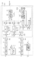
図1は、実施例1の信号処理部100の構成である。基準光P1及び測定光P2は、それぞれ第1および第2受光器2,12により電流に変換される。第1および第2受光器2,12として、例えば、PINフォトダイオードやアバランシェフォトダイオード等が用いられる。第1および第2受光器2,12の出力は、第1および第2I/V変換器4,14に入力されて電圧に変換される。第1および第2I/V変換器4,14は、例えば、抵抗とOPアンプにより構成される。第1および第2I/V変換器4,14の出力は、第1および第2フィルタ6,16に入力される。第1および第2フィルタは、LPF(Low Pass Filter)として高帯域を制限するか、又は、基準光P1および測定光P2が交流信号であるため、直流をカットし高帯域を制限するBPF(Band Pass Filter)としてもよい。その場合、式2、式3は、直流成分がカットされ、交流信号であるサイン項のみが検出され、式5、式6のように変形される。
P1’=(A/2)×sin(2π×fr×t+θr)・・・(5)
P2’=(B/2)*sin{2π×(fr+fd)×t+θd}・・・(6)
FIG. 1 illustrates a configuration of the
P1 ′ = (A / 2) × sin (2π × fr × t + θr) (5)
P2 ′ = (B / 2) * sin {2π × (fr + fd) × t + θd} (6)
第1および第2フィルタ6,16の出力は、第1および第2A/D変換器8,18に入力され、サンプリング周波数fspでサンプリングされてデジタル基準信号とデジタル測定信号とに変換される。このようにして取得されたデジタル信号は、デジタル信号処理部200に入力される。デジタル信号処理部200は、例えば、デジタル信号を高速に処理することが可能な、FPGAやASICやDSP等により構成される。ASICは、Application Specific Integrated Circuitの略称である。
The outputs of the first and
デジタル基準信号は、位相を同期する位相同期部(PLL:Phase Locked Loop)250に入力される。ここで、図10に基づいてPLL250の動作の説明を行う。デジタル基準信号は、位相比較器260に入力される。位相比較器260は、例えば、乗算器により構成される。位相比較器260の出力は、フィルタ演算部262に入力され、位相比較器260からの高調波成分を除去する。フィルタ演算部262の出力は積分演算部264に入力される。
The digital reference signal is input to a phase synchronization unit (PLL: Phase Locked Loop) 250 that synchronizes phases. Here, the operation of the
この積分演算部264による積分演算は、位相比較器260の出力偏差をゼロとするための積分制御用で、比例積分制御として安定な制御を行うよう構成してもよい。積分演算部264の出力は、加算器268に入力され、初期値266と加算される。初期値266は、第1周波数変調frに相当する初期値が設定されている。積分演算部270とサイン演算部272、及び、積分演算部270とコサイン演算部274は、VCO(Voltage Controlled Oscillator:電圧制御発振器)に相当するサイン信号とコサイン信号の生成部である。これらの動作は下式7、8で表される。ただし、積分演算部264の出力をVi、初期値266の出力をV0とする。
サイン信号=sin{∫(Vi+V0)dt}・・・(7)
コサイン信号=cos{∫(Vi+V0)dt}・・・(8)
The integration calculation by the
Sine signal = sin {∫ (V i + V 0 ) dt} (7)
Cosine signal = cos {∫ (V i + V 0 ) dt} (8)
サイン演算部272及びコサイン演算部274は、例えば、予め求められたサインとコサインの値をテーブルとしてメモリに保存しておき、式7、式8の{ }内の値に応じてテーブルを参照してサイン信号とコサイン信号を生成するよう構成してもよい。サイン信号の振幅レンジを12bit、時間分解能を10bit(×1024)とした場合に必要なメモリ容量は、12bit×1024=12.288kbitである。また、サイン信号の振幅レンジを16bit、時間分解能を12bit(×4096)とした場合に必要なメモリ容量は、16bit×4096=65.536kbitである。これらのメモリ容量は、FPGAやASIC、またはDSP等に内蔵されているメモリを使用することにより容易に実現することができる。また、PLL250の演算は、乗算器および加算器ともに数個程度で実現できるため、デジタル信号処理の演算負荷は極めて低くすることが可能となる。
The
コサイン演算部274の出力は位相比較器260にフィードバックされ、先に述べた積分演算部264により、位相比較器260の出力偏差がゼロとなるようにサイン信号とコサイン信号を生成する。出力偏差がゼロとなるため、デジタル基準信号と式7で与えられるサイン演算部272の出力P1_sinは完全に周波数と位相が同期する。また、式8で与えられるコサイン演算部274の出力P1_cosは、位相が90度ずれた同期信号となり、式9、式10で表される。ただし、Vbは振幅である。
P1_sin=Vb×sin(2π×fr×t+θr)・・・(9)
P1_cos=Vb×cos(2π×fr×t+θr)・・・(10)
The output of the
P1_sin = Vb × sin (2π × fr × t + θr) (9)
P1_cos = Vb × cos (2π × fr × t + θr) (10)
次に図1に戻り、デジタル信号処理部200の説明を続ける。PLL250で生成されたデジタル基準信号に同期したサイン信号P1_sinとコサイン信号P1_cosは、デジタル測定信号P2’に対し、第1および第2同期検波部10,20で乗算される。第1および第2同期検波部10,20は、例えば、乗算器で構成される。式6、式9、式10より第1および第2同期検波部10,20の出力は、それぞれ式11、式12で表される。
Next, returning to FIG. 1, the description of the digital
第1同期検波部10の出力
P2’×P1_cos
=(B/2)×sin{2π×(fr+fd)×t+θd}×Vb×cos(2π×fr×t+θr)
=(B×Vb/4)×[sin(2π×fd×t+θd−θr)+sin{2π×(2fr+fd)×t+θd+θr}]・・・(11)
第2同期検波部20の出力
P2’×P1_sin
=(B/2)×sin{2π×(fr+fd)×t+θd}×Vb×sin(2π×fr×t+θr)
=(B×Vb/4)×[cos(2π×fd×t+θd−θr)−cos{2π×(2fr+fd)×t+θd+θr}]・・・(12)
Output P2 ′ × P1_cos of the first
= (B / 2) × sin {2π × (fr + fd) × t + θd} × Vb × cos (2π × fr × t + θr)
= (B × Vb / 4) × [sin (2π × fd × t + θd−θr) + sin {2π × (2fr + fd) × t + θd + θr}] (11)
Output P2 ′ × P1_sin of the second
= (B / 2) × sin {2π × (fr + fd) × t + θd} × Vb × sin (2π × fr × t + θr)
= (B × Vb / 4) × [cos (2π × fd × t + θd−θr) −cos {2π × (2fr + fd) × t + θd + θr}] (12)
式11、式12の各最終式右辺の第1項は、対象物の移動速度に応じて発生する周波数fdの第2周波数の成分のコサイン部分とサイン部分である。また、式11、式12の各最終式右辺の第2項は、第1および第2同期検波部10,20で発生する周波数(2fr+fd)の高調波成分を含む項である。第1および第2同期検波部10,20は、測定信号を第1周波数で復調することによって前記第2周波数の成分、周波数がn×fd(ただしn=1/2、2、3、・・・)の周期誤差成分及び高調波成分を含む信号を生成する復調部を構成している。
The first term on the right side of each final expression in Expression 11 and
第1および第2同期検波部10,20の出力は、それぞれ第1および第2デシメーションフィルタ30,50に入力される。第1および第2デシメーションフィルタ30,50は、デジタル信号処理の演算負荷を低下させるため、デシメーション周波数でフィルタリングして、第1および第2同期検波部10,20で発生した周波数(2fr+fd)の高調波成分を減衰させる。
The outputs of the first and second
図9に基づいて第1および第2デシメーションフィルタ30,50の動作の説明を行う。第1、2デシメーションフィルタ30,50は、サンプリング周波数fspで動作する積分演算とデシメーション周波数fmで動作する微分演算により構成されるCICフィルタ(Cascaded Integrator−Comb Filter)であってもよい。この場合の第1および第2デシメーションフィルタの伝達関数は下式13で与えられる。ここで、H(f)はデシメーションフィルタの伝達関数、Dは遅延差(1または2)、mはデシメーション比(2以上の整数)、Nは積分器と微分器の段数である。
|H(f)|=|{sin(π×D×f/fsp)/sin(π×f/fsp/m)}N|・・・(13)
The operation of the first and second decimation filters 30 and 50 will be described with reference to FIG. The first and second decimation filters 30 and 50 may be CIC filters (cascaded integrator-comb filters) configured by an integral operation that operates at the sampling frequency fsp and a differential operation that operates at the decimation frequency fm. The transfer functions of the first and second decimation filters in this case are given by the following equation (13). Here, H (f) is a transfer function of a decimation filter, D is a delay difference (1 or 2), m is a decimation ratio (an integer of 2 or more), and N is the number of stages of an integrator and a differentiator.
| H (f) | = | {sin (π × D × f / fsp) / sin (π × f / fsp / m)} N | (13)
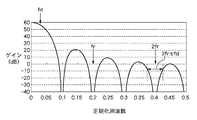
図9では、N=2の場合のCICフィルタの構成が示されている。ここでD=2、m=5、N=3とした場合のCICフィルタの特性例を図11に示す。fsp=100MHzであるが、この場合にデジタル信号処理できる信号周波数は50MHzであるため、横軸はサンプリング周波数100MHzに対して実際にデジタル信号処理される信号周波数との比を正規化周波数として表している。m=5より、デシメーション周波数fm=20MHzとなるが、この場合にデジタル信号処理される信号周波数はデシメーション周波数の1/2である10MHzとなる。このため、図11では、正規化周波数=0.1、即ち10MHzでゲインが急激に減衰するノッチ特性が現れる。図11には、fr=20MHz、fd=2.58MHzの場合が記されている。 FIG. 9 shows the configuration of the CIC filter when N = 2. FIG. 11 shows a characteristic example of the CIC filter when D = 2, m = 5, and N = 3. Although fsp = 100 MHz, the signal frequency that can be digitally processed in this case is 50 MHz. Therefore, the horizontal axis represents the ratio between the sampling frequency of 100 MHz and the signal frequency that is actually digitally processed as a normalized frequency. Yes. From m = 5, the decimation frequency fm = 20 MHz. In this case, the signal frequency for digital signal processing is 10 MHz, which is ½ of the decimation frequency. For this reason, in FIG. 11, a notch characteristic in which the gain rapidly attenuates at the normalized frequency = 0.1, that is, 10 MHz appears. FIG. 11 shows the case of fr = 20 MHz and fd = 2.58 MHz.
図11には、fr=20MHz、fd=2.58MHzの場合が記されている。第1および第2同期検波部10,20による高調波成分の周波数は、(2fr+fd)=40±2.58MHzとなり、ICフィルタのノッチ特性で効率的に除去されることが分かる。第1および第2デシメーションフィルタ30,50は、復調部で生成された信号から高調波成分を除去して第2周波数の成分及び周期誤差成分を含む信号を出力するデシメーションフィルタを構成している。
FIG. 11 shows the case of fr = 20 MHz and fd = 2.58 MHz. It can be seen that the frequency of the harmonic component by the first and second
次に図1に戻りデジタル信号処理部200の説明を続ける。第1および第2デシメーションフィルタ30,50の出力は、位相演算部60に入力され、位相演算部60の出力は位置演算部70に入力される。位相演算部60は、第1および第2デシメーションフィルタ30,50からの信号より下式14のアークタンジェント演算を行う。
位相角
=tan−1[B×Vb/4×sin(2π×fd×t+θd−θr)
/{B×Vb/4×cos(2π×fd×t+θd−θr)}]
=tan−1 {sin(2π×fd×t+θd−θr)
/cos(2π×fd×t+θd−θr)}・・・(14)
Next, returning to FIG. 1, the description of the digital
Phase angle = tan −1 [B × Vb / 4 × sin (2π × fd × t + θd−θr)
/ {B × Vb / 4 × cos (2π × fd × t + θd−θr)}]
= Tan −1 {sin (2π × fd × t + θd−θr)
/ Cos (2π × fd × t + θd−θr)} (14)
式14よりデジタル基準信号とデジタル測定信号との位相差が算出される。位置演算部70は、位相演算部60からの位相差を位置または変位に変換する。例えば、対象物の位置または変位Lは、式4式より下式15で表される。ここで、θは位相角である。
L=(λ/j)×∫(fd)dt
={(λ/j)/(2π)}×θ・・・(15)
From
L = (λ / j) × ∫ (fd) dt
= {(Λ / j) / (2π)} × θ (15)
位置係数(λ/j)は、式15より、λ=1.55μm、j=4の場合、(λ/j)=387.5nmである。これは、位相角の出力θ=2πのときにL=387.5nmの位置または変位となることを表す。式14の位相角の時間微分、または、式15の位置または変位の時間微分は、対象物の移動速度に応じたドップラーシフトによる周波数シフトfdに応じた値を示す。
ここで、第2周波数frに対応する第2角周波数ωdは下式16で表される。
ωd=2π×fd・・・(16)
The position coefficient (λ / j) is (λ / j) = 387.5 nm when λ = 1.55 μm and j = 4 from Equation 15. This represents a position or displacement of L = 387.5 nm when the phase angle output θ = 2π. The time derivative of the phase angle in
Here, the second angular frequency ωd corresponding to the second frequency fr is expressed by the following
ωd = 2π × fd (16)
図1では、位相演算部60にてωdを算出して信号生成部380に出力する例が示されているが、上記のように位置演算部70にてωdを算出するよう構成してもよい。尚、第1および第2A/D変換器8,18、第1および第2デシメーションフィルタ30,50、周波数変調駆動部92へのタイミング周波数fsp、fm、frは、タイミング生成部80にて生成される。位相演算部60、位置演算部70は、除去部から出力された信号に基づいて前記対象物の位置を演算する演算部を構成している。また、位相演算部60、位置演算部70は、デシメーションフィルタから出力された信号から基準信号と測定信号の位相差の変化量又は対象物の位置の変化量の暫定値を演算し、該演算された変化量の暫定値から第2周波数の暫定値を演算する演算部を構成している。
Although FIG. 1 shows an example in which ωd is calculated by the
干渉計からの測定光には、干渉計を構成する光学部品における反射や散乱、および不完全性により上記ドップラーシフトに依存した第2周波数fdに対して周期的な誤差信号(周期誤差成分)が重畳する場合がある。周期誤差成分の周波数は、光学部品の配置や特性により異なり、例えばfd/2、2fd、3fd、・・・等の低次から高次までの様々な周波数を含む場合がある。この周期誤差成分により位置演算部70の出力には測長誤差が発生する。周期誤差成分の検出除去部300は、第1角周波数ωr(=2π×fr)で復調して得られる復調信号に含まれる不要な誤差信号nωd(n=1/2、2、3、・・・)を検出する。図1では、誤差信号nωdの検出に、第2デシメーションフィルタ50の出力を使用する例が示されているが、第1デシメーションフィルタ30の出力を使用するよう構成してもよい。
The measurement light from the interferometer has a periodic error signal (periodic error component) with respect to the second frequency fd depending on the Doppler shift due to reflection, scattering, and imperfection in the optical components constituting the interferometer. May overlap. The frequency of the cyclic error component varies depending on the arrangement and characteristics of the optical component, and may include various frequencies from low to high, such as fd / 2, 2fd, 3fd,. Due to this cyclic error component, a length measurement error occurs in the output of the
図2に、入力信号(ωr+nωd、n=1/2、1、-1、2、3)と、復調に用いる信号(×ωr、×(ωr−ωd)、×(ωr+2ωd))に対する復調信号としての出力と高調波成分を示す。実施例1では、第1角周波数ωrにより復調を行う。この場合の復調信号に含まれる不要な誤差信号は、左側の欄の太実線で囲まれた(1/2)ωd、2ωd、3ωdである。このとき、入力信号(ωr+ωd)に対する復調信号の出力はωdとなり、(ωr−ωd)に対する復調信号の出力は−ωdとなる。このため、両者の復調信号の周波数は同一となり、合成されてしまうため分離して検出することはできない。一方、高調波成分は、(2ωr+nωd)の高い周波数となるため、第1または第2デシメーションフィルタ30,50により除去される。 FIG. 2 shows a demodulated signal for an input signal (ωr + nωd, n = 1/2, 1, −1, 2, 3) and signals used for demodulation (× ωr, × (ωr−ωd), × (ωr + 2ωd)). Shows the output and harmonic components. In the first embodiment, demodulation is performed using the first angular frequency ωr. In this case, unnecessary error signals included in the demodulated signal are (1/2) ωd, 2ωd, and 3ωd surrounded by a thick solid line in the left column. At this time, the output of the demodulated signal for the input signal (ωr + ωd) is ωd, and the output of the demodulated signal for (ωr−ωd) is −ωd. For this reason, both demodulated signals have the same frequency and are combined and cannot be detected separately. On the other hand, since the harmonic component has a high frequency of (2ωr + nωd), it is removed by the first or second decimation filters 30 and 50.
第2デシメーションフィルタ50からの出力信号は、必要に応じてフィルタ306により、更にフィルタリングされてもよいし、デシメーションフィルタによりデシメーション及びフィルタリングを行ってもよい。周波数解析部320は、フーリエ変換演算を行う演算部である。周波数解析部320は、演算負荷を低減するため、FFT(Fast Fourier Transform)演算を行ってもよい。FFTは複素加算と複素乗算による演算で構成され、サンプル数をNと置くと、各演算回数は式17、式18で表される。
複素加算=N×log2N・・・(17)
複素乗算=N/2×log2N・・・(18)
The output signal from the
Complex addition = N × log 2 N (17)
Complex multiplication = N / 2 × log 2 N (18)
サンプリング周波数fspとFFTによる周波数分解能Δfとは、式19で表される関係にある。
Δf=fsp/N・・・(19)
The sampling frequency fsp and the frequency resolution Δf by FFT have a relationship represented by Expression 19.
Δf = fsp / N (19)
本実施例では、測定信号を第1角周波数ωrで復調して復調信号を生成し、デシメーションフィルタ30,50に入力して不要な信号の振幅と位相を算出する。そのため、ωrの第1角周波数成分が除去され、ωrの角周波数に対し十分低い角周波数で信号検出の演算を行うことができる。例えば、サンプリング周波数fspを100MHz、ωrによる復調後のデシメーションフィルタ50によるデシメーション周波数fmを20MHz、フィルタ306によるデシメーション周波数fm2を10MHzとする。その場合の周波数解析部320のFFT演算は、サンプル数Nが128の場合、複素加算回数が896、複素乗算回数が448、周波数分解能Δfが78.13kHzとなる。例えば、λが1.55μmの光源で、j=4の場合、fd=78.13kHz〜5MHz、即ち、速度v=0.03〜1.94m/sにおける復調信号に含まれる角周波数nωd(n=1/2、2、3、・・・)の周期誤差成分を検出することができる。尚、この演算を78.13kHz毎に行う場合、1秒間に複素加算は7.00×107回、複素乗算は3.5×107回の演算が必要となる。FPAG等の高速演算器では、加算、乗算を100MHz(108)以上のサイクルで実行することが可能であり、上記の演算を極めて少ない演算負荷で容易に実行することができる。
In the present embodiment, the measurement signal is demodulated at the first angular frequency ωr to generate a demodulated signal, which is input to the decimation filters 30 and 50 to calculate the amplitude and phase of unnecessary signals. Therefore, the first angular frequency component of ωr is removed, and signal detection calculation can be performed at an angular frequency sufficiently lower than the angular frequency of ωr. For example, the sampling frequency fsp is 100 MHz, the decimation frequency fm by the
このように、実施例1では、検出除去部300は、測定信号を第1角周波数ωrで復調し、デシメーションフィルタに入力した後、角周波数nωd(n=1/2、2、3、・・・)の周期誤差成分をFFT等でフーリエ変換演算を行うことにより検出する。このため、ωrの角周波数成分が除去され、角周波数ωrに対し十分低い角周波数で周期誤差成分を検出するための演算を行うことができる。従って、対象物の位置または変位を測定するヘテロダイン干渉計において、デジタル信号処理の演算負荷を低減してドップラーシフトに対する低次から高次までの様々な周期誤差成分の補正を行い、低コストで高精度な位置または変位を測定することが可能となる。周波数解析部320は、周期誤差成分nωd(n=1/2、2、3、・・・)の振幅と位相を算出し、出力する。信号生成部380はこの振幅と位相より、測定信号に含まれる周期誤差成分を除去するための信号A0,B0を生成する。
Thus, in the first embodiment, the detection and
図3により信号生成部380の動作の説明を行う。周波数解析部320より周期誤差成分nωd(n=1/2、2、3、・・・)の振幅AMPと位相OFSが入力される。また、位相演算部60(または位置演算部70)よりωdの暫定値が入力される。ωdの暫定値は乗算器382にて不要な誤差信号の次数n(n=1/2、2、3、・・・)と乗算され、nωdが出力される。サイン/コサイン生成部384では、(nωd×t+OFS)の演算が行われ、この値によるサイン信号とコサイン信号が出力される。ここでtは時間である。
The operation of the
サイン信号とコサイン信号の生成は、例えば、予め求められたサインとコサインの値をテーブルとしてメモリに保存しておき、(nωd×t+OFS)の値に応じてテーブルを参照してサイン信号とコサイン信号を生成するよう構成してもよい。振幅レンジを10bit、時間分解能を10bit(×1024)、とした場合に必要なメモリ容量は、10bit×1024=10.24kbitである。サイン/コサイン生成部384からのサイン信号とコサイン信号は、乗算器386,388にて振幅AMPが乗算される。これにより、信号生成部380からの出力信号は、周期誤差成分nωd(n=1/2、2、3、・・・)に対し、振幅と位相が一致した信号となる。
The generation of the sine signal and the cosine signal is performed by, for example, storing the sine and cosine values obtained in advance as a table in a memory and referring to the table according to the value of (nωd × t + OFS). May be configured to generate. The required memory capacity when the amplitude range is 10 bits and the time resolution is 10 bits (× 1024) is 10 bits × 1024 = 10.24 kbit. The sine signal and the cosine signal from the sine /
乗算器386,388からの出力信号A0,B0即ち除去信号は、加減算器302,304に入力され、第1および第2デシメーションフィルタ30,50からの測定信号に含まれる不要な周期誤差成分を除去する。信号生成部380で生成する信号は、測定信号に含まれる周期誤差成分の次数n(n=1/2、2、3、・・・)に対し、例えば、n=1/2の信号のみの場合や、n=1/2、2、3の複数の信号の場合が有り得る。これらの周期誤差成分は、干渉計を構成する光学部品における反射や散乱、および不完全性により発生し、周期誤差成分の周波数は、光学部品の配置や特性により異なるため、設計や部品特性に応じて生成する信号を決定すればよい。複数の周期誤差成分を除去する場合、複数の信号生成部380を設けて複数の除去信号を生成し、それらの除去信号を加減算器302,304にて加算して、測定信号に含まれる不要な周期誤差成分を除去するよう構成してもよい。
Output signals A0 and B0 from the
実施例1のフィルタ306、周波数解析部320、信号生成部380は、デシメーションフィルタ30、50から出力された信号に含まれる周期誤差成分を検出する検出部を構成している。また、加減算器302,304は、デシメーションフィルタ30、50から出力された信号から検出部により検出された周期誤差成分を除去して第2周波数の成分の信号を出力する除去部を構成している。
The
従って、本発明によれば、測定信号を第1角周波数ωrで復調し、デシメーションフィルタ30、50により高調波を除去するとともにそれ以降のデジタル信号処理の処理速度を低下させて周期誤差成分を検出して除去する。これにより、周期誤差成分の検出に必要なデジタル信号処理部の演算負荷を著しく低減させることができ、ドップラーシフトに対する低次から高次までの様々な周期誤差成分を除去して高精度で且つ低コストな位置または変位の測定装置を構成することが可能となる。 Therefore, according to the present invention, the measurement signal is demodulated at the first angular frequency ωr, the harmonics are removed by the decimation filters 30 and 50, and the processing speed of the subsequent digital signal processing is reduced to detect the cyclic error component. And remove. As a result, it is possible to remarkably reduce the calculation load of the digital signal processing unit necessary for detecting the cyclic error component, and it is possible to remove various cyclic error components from the low order to the high order with respect to the Doppler shift with high accuracy and low An expensive position or displacement measuring device can be configured.
[実施例2]
次に、図4に基づいて実施例2を説明する。実施例1と同じ動作をするものは同じ番号を付け、その説明を割愛する。実施例1と異なる構成は、検出除去部300aである。測定信号に含まれる周期誤差成分の振幅と位相を求めるため、実施例2の周期誤差成分を検出し、除去する検出除去部300aは、実施例1で用いたフーリエ変換演算を行う周波数解析部320に代わり、第3および第4同期検波部310,312を有する。測定信号を角周波数ωrで復調して得られた復調信号に対し、更に、nωd(n=1/2、2、3、・・・)の周波数を有する周期誤差成分のコサイン信号またはサイン信号を乗算することにより第3および第4同期検波部310,312により復調を行う。
[Example 2]
Next, Example 2 will be described with reference to FIG. Components that perform the same operations as in the first embodiment are given the same numbers, and descriptions thereof are omitted. A configuration different from the first embodiment is a
図2を参照すると、入力信号(ωr+nωd、n=1/2、1、-1、2、3)に対して復調に用いる信号をωrとした場合の復調信号に含まれる周期誤差成分は、左側欄の太実線で囲まれた(1/2)ωd、2ωd、3ωdである。この時、入力信号(ωr+ωd)に対する復調信号の出力はωdとなり、(ωr−ωd)に対する復調信号の出力は−ωdとなる。このため、両者の周波数は同一となり、合成されてしまうため分離して検出することはできない。一方、高調波成分は、(2ωr+nωd)の高い周波数となるため、第1または第2デシメーションフィルタ30,50により除去される。信号生成部380aでは、第3および第4同期検波部310,312に入力するnωd(n=1/2、2、3、・・・)の周波数を有する周期誤差成分のコサイン信号とサイン信号を生成する。
Referring to FIG. 2, the cyclic error component included in the demodulated signal when the signal used for demodulation is ωr with respect to the input signal (ωr + nωd, n = 1/2, 1, −1, 2, 3) is (1/2) ωd, 2ωd, and 3ωd surrounded by a thick solid line in the column. At this time, the output of the demodulated signal for the input signal (ωr + ωd) is ωd, and the output of the demodulated signal for (ωr−ωd) is −ωd. For this reason, both frequencies become the same, and since they are combined, they cannot be detected separately. On the other hand, since the harmonic component has a high frequency of (2ωr + nωd), it is removed by the first or second decimation filters 30 and 50. In the
図5に信号生成部380aの構成図を示す。位相演算部60よりωdが入力される。実施例1で説明したように、位置演算部70にてωdを算出するよう構成してもよい。ωdは乗算器382にて周期誤差成分の次数n(n=1/2、2、3、・・・)と乗算され、nωdが出力される。サイン/コサイン生成部384aでは、nωd×tの演算が行われ、この値によるサイン信号とコサイン信号が出力される。ここでtは時間である。サイン信号とコサイン信号の生成は、例えば、予め求められたサインとコサインの値をテーブルとしてメモリに保存しておき、(nωd×t)の値に応じてテーブルを参照してサイン信号とコサイン信号を生成するよう構成してもよい。
FIG. 5 shows a configuration diagram of the
振幅レンジを10bit、時間分解能を10bit(×1024)、とした場合に必要なメモリ容量は、10bit×1024=10.24kbitである。サイン/コサイン生成部384aからのコサイン信号とサイン信号は、第3および第4同期検波部310,312に入力され、第2デシメーションフィルタ50からの出力信号を復調する。尚、図4では、第2デシメーションフィルタ50からの信号を第3および第4同期検波部310,312により復調しているが、第1デシメーションフィルタ30からの信号を復調するよう構成しても良い。
The required memory capacity when the amplitude range is 10 bits and the time resolution is 10 bits (× 1024) is 10 bits × 1024 = 10.24 kbit. The cosine signal and sine signal from the sine /
第3および第4同期検波部310,312の出力はフィルタ307,308に入力される。フィルタ307,308は、LPF(Low Pass filter)であってもよいし、CICフィルタ等によるデシメーションフィルタでもよい。フィルタ307,308からの信号は振幅位相演算部330に入力される。
The outputs of the third and fourth
第2同期検波部20により周波数変調成分である第1周波数ωrは除去され、第2デシメーションフィルタ50の出力は、ωd及び周期誤差成分nωd(n=1/2、2、3、・・・)となる。第3および第4同期検波部310,312は、信号生成部380aからの信号であるcos(2π×n×fd×t)とsin(2π×n×fd×t)により、下式20、21のような復調信号を生成する。ここで、Vnは第2デシメーションフィルタ50からの周期誤差成分の振幅であり、θnは第2デシメーションフィルタ50からの周期誤差成分の位相である。
Vn×cos(2π×n×fd×t+θn)×cos(2π×n×fd×t)
=Vn/2×{cos(θn)+cos(4π×n×fd×t+θn)}・・・(20)
Vn×cos(2π×n×fd×t+θn)×sin(2π×n×fd×t)
=Vn/2×{−sin(θn)+sin(4π×n×fd×t+θn)}・・・(21)
The second
Vn × cos (2π × n × fd × t + θn) × cos (2π × n × fd × t)
= Vn / 2 × {cos (θn) + cos (4π × n × fd × t + θn)} (20)
Vn × cos (2π × n × fd × t + θn) × sin (2π × n × fd × t)
= Vn / 2 * {-sin (θn) + sin (4π × n × fd × t + θn)} (21)
式20、式21の右辺の第2項は高調波成分で、フィルタ307,308で除去される。従って、フィルタ307,308の出力信号は下式22,23で表される。
フィルタ307の出力=Vn/2×cos(θn)・・・(22)
フィルタ308の出力=−Vn/2×sin(θn)・・・(23)
The second term on the right side of
Output of
Output of
振幅位相演算部330は式22、式23で表される入力信号に対し図6に示すような演算を行う。即ち、下式24,25の演算を行う。
振幅AMP=√[{Vn/2×cos(θn)}2+
{−Vn/2×sin(θn)}2]×√2
=Vn・・・(24)
位相OFS=atan[{−Vn/2×sin(θn)}/
{Vn/2×cos(θn)}]×(−1)
=atan{sin(θn)/cos(θn)}・・・(25)
The amplitude /
Amplitude AMP = √ [{Vn / 2 × cos (θn)} 2 +
{−Vn / 2 × sin (θn)} 2 ] × √2
= Vn (24)
Phase OFS = atan [{−Vn / 2 × sin (θn)} /
{Vn / 2 × cos (θn)}] × (−1)
= Atan {sin (θn) / cos (θn)} (25)
これにより、周期誤差成分nωd(n=1/2、2、3、・・・)の振幅Vnと位相θnを算出することができる。この振幅と位相より、測定信号に含まれる周期誤差成分を除去するための除去信号を生成する方法は、実施例1と同様である。例えば、λ=1.55μmの光源で、j=4、fd=78.13kHz〜5MHz、即ち、速度v=0.03〜1.94m/s、fr=20MHzにおける復調信号に含まれる周期誤差成分を検出する場合考える。サンプリング周波数fsp=100MHz、ωrによる復調後の第2のデシメーションフィルタ50によるデシメーション周波数fm=20MHzとする。第3および第4の同期検波部310,312の出力は、式20、式21の右辺第1項の周期誤差成分の位相θnと、第2項の高調波成分(4π×n×fd×t+θn)で表される。検出すべき振幅Vnと位相θnは直流信号で表され、フィルタ307,308により高調波成分を除去する。
Thereby, the amplitude Vn and the phase θn of the cyclic error component nωd (n = 1/2, 2, 3,...) Can be calculated. A method of generating a removal signal for removing the cyclic error component included in the measurement signal from the amplitude and phase is the same as that in the first embodiment. For example, with a light source of λ = 1.55 μm, j = 4, fd = 78.13 kHz to 5 MHz, that is, a cyclic error component included in a demodulated signal at a speed v = 0.03 to 1.94 m / s, fr = 20 MHz Think when you detect. Sampling frequency fsp = 100 MHz, and decimation frequency fm = 20 MHz by
例えばn=1/2の場合、高調波成分は2×n×fd=78.13kHz〜5MHzとなる。また、図2に示した入力信号と×ωrによる復調信号における信号の振幅は、測定信号である(ωr+ωd)とωrにより生じるωd成分が最も大きい。(1/2)ωdで復調した場合、両者の差分である(1/2)ωd=39.07kHzが復調信号に現れる。ここで、フィルタ307,308に図11に示すようなデシメーションフィルタを用いた場合を考える。デシメーション周波数fm2=100kHzとすると、検出すべき振幅Vnと位相θn(直流信号)に対して除去すべき(1/2)ωd=39.07kHz(正規化周波数=0.4付近)は、−60dB以下の除去率となり、十分な除去率を得ることができる。
For example, when n = 1/2, the harmonic component is 2 × n × fd = 78.13 kHz to 5 MHz. Further, the amplitude of the input signal shown in FIG. 2 and the signal demodulated by xωr has the largest ωd component generated by the measurement signal (ωr + ωd) and ωr. When demodulating with (1/2) ωd, the difference between them (1/2) ωd = 39.07 kHz appears in the demodulated signal. Here, a case where a decimation filter as shown in FIG. 11 is used for the
このように、実施例2では、測定信号を角周波数ωrで復調して復調信号を生成し、デシメーションフィルタ30、50により高調波を除去するとともにそれ以降のデジタル信号処理の処理速度を低下させる。更に、復調信号に対し周波数nωd(n=1/2、2、3、・・・)のサイン信号とコサイン信号により復調を行う第3、第4同期検波部310,312と該同期検波部からの信号に対するフィルタ(またはデシメーションフィルタ)307,308を有する。これにより検出すべき周期誤差成分の振幅と位相は直流信号となり、フィルタ307,308により高調波成分が除去され、デジタル信号処理の処理速度を低下させて周期誤差成分を検出して除去することが可能となる。また、実施例2では、周期誤差成分nωd(n=1/2、2、3、・・・)の周波数成分を位相演算部60または位置演算部70で算出したωdより生成する。このため対象物が大きな加速度で移動し、ωdの値が大きく変化する場合でも正確なnωdの周期誤差成分の信号を生成することができ、より正確に周期誤差成分を検出することが可能となり、高精度な干渉計を構成することができる。
As described above, in the second embodiment, the demodulated signal is generated by demodulating the measurement signal at the angular frequency ωr, the harmonics are removed by the decimation filters 30 and 50, and the processing speed of the subsequent digital signal processing is reduced. Further, third and fourth
実施例2における検出除去部300aで検出および除去可能な測定信号に含まれる周期誤差成分の次数nは、n=1/2、2、3、・・・である。例えば、n=1/2の信号のみの場合や、n=1/2、2、3の複数の信号の場合が有り得る。これらの誤差信号は、干渉計を構成する光学部品における反射や散乱、および不完全性により発生し、周期誤差成分の周波数は、光学部品の配置や特性により異なるため、設計や部品特性に応じて生成する周期誤差成分を決定すればよい。複数の周期誤差成分を除去する場合、複数組の第3、第4同期検波部、フィルタ、振幅位相演算部、信号生成部を設けて複数の除去信号を生成し、それらの除去信号を加減算器302,304にて加算して、測定信号に含まれる周期誤差成分を除去しうる。
The order n of the cyclic error component included in the measurement signal that can be detected and removed by the
なお、実施例2では、周期誤差成分の検出に、実施例1のFFTに代えて、第3、第4同期検波部310,312と該同期検波部からの信号に対するフィルタ(またはデシメーションフィルタ)307,308を用いる。第2のデシメーションフィルタ50によるデシメーション周波数fm=20MHzとすると、第3、第4同期検波部310、312の乗算演算の回数は共に2×10⁷回で、フィルタ(又はデシメーションフィルタ)307,308においても同等の演算回数となる。FPAG等の高速演算器では、加算、乗算を100MHz(108)以上のサイクルで実行することが可能であり、上記の演算を極めて少ない演算負荷で容易に実行することができる。従って、実施例2によれば、デジタル信号処理の演算負荷を低減してドップラーシフトに対する低次から高次までの様々な周期誤差成分を検出して除去し、低コストで高精度な位置または変位を測定することが可能となる。また、対象物が大きな加速度で移動する場合でも周期誤差成分nωd(n=1/2、2、3、・・・)を正確に検出することが可能となり、より高精度な干渉計を構成することができる。
In the second embodiment, instead of the FFT in the first embodiment, the cyclic error component is detected by the third and fourth
[実施例3]
次に、図7に基づいて実施例3を説明する。実施例1、実施例2と同じ動作をするものは同じ番号を付け、その説明を割愛する。実施例1と異なる構成は、周期誤差成分を検出し除去する検出除去部300bである。実施例3と実施例1及び実施例2との差異は、測定信号に含まれる−ωdの周期誤差成分の振幅と位相を検出可能な点である。尚、実施例3においても、実施例1及び実施例2と同様に、nωd(n=1/2、2、3、・・・)の周期誤差成分を検出することが可能である。
[Example 3]
Next, Example 3 will be described with reference to FIG. Components that perform the same operations as those in the first embodiment and the second embodiment are given the same numbers, and the description thereof is omitted. A configuration different from that of the first embodiment is a
測定信号に含まれる周期誤差成分は、干渉計を構成する光学部品における反射や散乱、および不完全性により発生し、周期誤差成分の周波数は、光学部品の配置や特性により異なる。実施例1及び実施例2では、周期誤差成分nωdの次数n(n=1/2、2、3、・・・)において、一つの次数の場合や複数の次数を検出する場合の例を挙げた。しかしながら、光学部品の配置や特性によっては、n=−1の場合も起こり得る。図2に示す通り、入力信号(ωr+nωd、n=1/2、1、-1、2、3)に対して復調に用いる信号を(×ωr)とした場合、入力信号(ωr+ωd)に対する復調信号の出力はωdとなり、(ωr−ωd)に対する復調信号の出力は−ωdとなる。このため、両者の周波数は同一となり、合成されてしまうため分離して検出することはできない。 The periodic error component included in the measurement signal is generated due to reflection, scattering, and imperfection in the optical component constituting the interferometer, and the frequency of the periodic error component varies depending on the arrangement and characteristics of the optical component. In the first embodiment and the second embodiment, an example in which one order or a plurality of orders is detected in the order n (n = 1/2, 2, 3,...) Of the cyclic error component nωd is given. It was. However, depending on the arrangement and characteristics of the optical component, a case where n = −1 may occur. As shown in FIG. 2, when the signal used for demodulation is (× ωr) for the input signal (ωr + nωd, n = 1/2, 1, −1, 2, 3), the demodulated signal for the input signal (ωr + ωd) Output becomes ωd, and the output of the demodulated signal with respect to (ωr−ωd) becomes −ωd. For this reason, both frequencies become the same, and since they are combined, they cannot be detected separately.
そこで図7に示すように、測定信号に含まれる周期誤差成分の振幅と位相を求めるため、測定信号のA/D変換器8の出力を第3、第4同期検波部310,312に入力し、変調成分と周波数(ωr−ωd)のサイン信号及びコサイン信号とにより復調を行う。この場合、復調信号において、図2の中央の×(ωr−ωd)の出力の太実線で囲まれた0、即ち、直流信号が検出すべき周期誤差成分−ωdの信号成分となる。その他の周期誤差成分nωd(n=1/2、2、3、・・・)は、(3/2)ωd、2ωd、3ωd、4ωdとなり、ωdの高調波となる。
Therefore, as shown in FIG. 7, in order to obtain the amplitude and phase of the cyclic error component included in the measurement signal, the output of the A /
図8に信号生成部380bの構成図を示す。位相演算部60よりωdが入力される。実施例1で説明したように、位置演算部70にてωdを算出するよう構成してもよい。ωdは乗算器382にて次数n=−1と乗算され、(−ωd)が出力される。一方、PLL250からの基準信号に同期したサイン信号とコサイン信号が入力され、サイン/コサイン生成部384bで、(ωr−ωd)×tの演算が行われ、この値によるサイン信号とコサイン信号が出力される。ここでtは時間である。尚、PLL250からの信号は、基準信号に同期した角周波数信号ωrであってもよい。
FIG. 8 shows a configuration diagram of the
サイン信号とコサイン信号の生成は、例えば、予め求められたサインとコサインの値をテーブルとしてメモリに保存しておき、(ωr−ωd)×tの値に応じてテーブルを参照してサイン信号とコサイン信号を生成するよう構成してもよい。振幅レンジを10bit、時間分解能を10bit(×1024)、とした場合に必要なメモリ容量は、10bit×1024=10.24kbitである。サイン/コサイン生成部384bからのコサイン信号とサイン信号は、第3および第4同期検波部310,312に入力され、測定信号のA/D変換器8からの出力信号を復調する。
The generation of the sine signal and the cosine signal is performed by, for example, storing the sine and cosine values obtained in advance in a memory as a table and referring to the table according to the value of (ωr−ωd) × t A cosine signal may be generated. The required memory capacity when the amplitude range is 10 bits and the time resolution is 10 bits (× 1024) is 10 bits × 1024 = 10.24 kbit. The cosine signal and sine signal from the sine /
第3および第4同期検波部310,312の出力はフィルタ307,308に入力される。フィルタ307,308は、LPF(Low Pass filter)であってもよいし、CICフィルタ等によるデシメーションフィルタでもよい。フィルタ307,308からの信号は振幅位相演算部330に入力される。また、サイン/コサイン生成部384bでは、振幅位相演算部330からの位相OFS信号により、(−ωd)×t+OFSの演算が行われ、この値によるサイン信号とコサイン信号が出力される。これ以外の構成と動作は、実施例1及び実施例2と同様である。
The outputs of the third and fourth
ここで、第3および第4同期検波部310,312からの復調信号は、信号生成部380bからの信号であるcos{2π×(fr−fd)×t}とsin{2π×(fr−fd)×t}により、式26,式27のような信号を生成する。ここで、Vnはデシメーションフィルタからの周期誤差成分の振幅、θnはデシメーションフィルタからの周期誤差成分の位相である。
Vn×cos{2π×(fr−fd)×t+θn}×cos{2π×(fr−fd)×t}
=Vn/2×{cos(θn)+cos(4π×(fr−fd)×t+θn)}・・・(26)
Vn×cos{2π×(fr−fd)×t+θn}×sin{2π×(fr−fd)×t}
=Vn/2×{−sin(θn)+sin(4π×(fr−fd)×t+θn)}・・・(27)
Here, the demodulated signals from the third and fourth
Vn × cos {2π × (fr−fd) × t + θn} × cos {2π × (fr−fd) × t}
= Vn / 2 × {cos (θn) + cos (4π × (fr−fd) × t + θn)} (26)
Vn × cos {2π × (fr−fd) × t + θn} × sin {2π × (fr−fd) × t}
= Vn / 2 * {-sin ([theta] n) + sin (4 [pi] * (fr-fd) * t + [theta] n)} (27)
式26、式27の右辺第2項は高調波成分で、フィルタ307,308で除去される。右辺第1項が検出すべき周期誤差成分−ωdの成分で、振幅と位相が直流信号として検出される。従って、フィルタ307,308の出力信号は実施例2で説明した式22、式23で表される。
The second term on the right side of Equation 26 and Equation 27 is a harmonic component and is removed by the
以上、実施例3として測定信号に含まれる−ωdの周期誤差成分の振幅と位相の検出方法に関する説明を行ったが、実施例1及び実施例2と同様に、nωd(n=1/2、2、3、・・・)の周期誤差成分を検出することが可能である。図2の右側に入力信号×(ωr+2ωd)とした場合の復調信号の周波数成分を示す。この場合、太実線で囲まれた0、即ち、直流信号が検出すべき周期誤差成分+2ωdの成分となる。その他の周期誤差成分nωd(n=1/2、1、−1、3、・・・)は、(−3/2)ωd、−ωd、−3ωd、ωdとなり、ωdの高調波となる。これらの高調波はフィルタ307,308で除去される。
As described above, the method for detecting the amplitude and phase of the cyclic error component of −ωd included in the measurement signal has been described as the third embodiment. However, similarly to the first and second embodiments, nωd (n = 1/2, 2, 3,...) Can be detected. The frequency component of the demodulated signal when the input signal × (ωr + 2ωd) is shown on the right side of FIG. In this case, 0 surrounded by a thick solid line, that is, a component of the cyclic error component + 2ωd to be detected by the DC signal. Other periodic error components nωd (n = 1/2, 1, −1, 3,...) Are (−3/2) ωd, −ωd, −3ωd, and ωd, and are harmonics of ωd. These harmonics are removed by
実施例3の実施例2との差異は、測定信号を角周波数(ωr+nωd)(n=1/2、−1、2、3、・・・)の周波数成分を有するサイン信号とコサイン信号により復調して復調信号を生成する第3および第4同期検波部310,312の動作周波数である。例えば、第3および第4同期検波部310,312は、サンプリング周波数fsp=100MHzで測定信号と(ωr−ωd)の乗算を行う。それ以降のフィルタ307,308によるデシメーション周波数は、実施例2と同様で、例えば、fm2=100kHzとして振幅位相演算部330を構成することができる。従って、実施例3においても、変調ωrの周波数に対し十分低い周波数で周期誤差成分を検出するための演算を行うことができる。例えば、第3および第4同期検波部310,312の周波数をfsp=100MHzとすると、乗算演算の回数は、それぞれ108回である。フィルタ(またはデシメーションフィルタ)307,308以降はデシメーション周波数を例えばfm2=100kHzとすると、演算回数は著しく低減される。FPAG等の高速演算器では、加算、乗算を100MHz(108)以上のサイクルで実行することが可能であり、上記の演算を極めて少ない演算負荷で容易に実行することができる。
The difference between the third embodiment and the second embodiment is that the measurement signal is demodulated by a sine signal and a cosine signal having frequency components of an angular frequency (ωr + nωd) (n = 1/2, −1, 2, 3,...). This is the operating frequency of the third and fourth
このように、実施例3では、測定信号を角周波数(ωr+nωd)(n=1/2、−1、2、3、・・・)の周波数成分を有するサイン信号とコサイン信号により復調して復調信号を生成し、フィルタ307,308によりωrの周波数成分及び高調波が除去される。これにより検出すべき周期誤差成分の振幅と位相は直流信号となり、ωrの周波数に対しデジタル信号処理の処理速度を低下させて周期誤差成分を検出して除去することが可能となる。また、誤差信号−ωdの成分を位相演算部60または位置演算部70で算出したωdより生成する。このため対象物が大きな加速度で移動し、ωdの値が大きく変化する場合でも正確なnωdの信号を生成することができ、より正確に誤差信号を検出することが可能となり、高精度な干渉計を構成することができる。
As described above, in the third embodiment, the measurement signal is demodulated by demodulating the sine signal and the cosine signal having frequency components of the angular frequency (ωr + nωd) (n = 1/2, −1, 2, 3,...). A signal is generated, and the frequency components and harmonics of ωr are removed by the
従って、実施例3によれば、デジタル信号処理の演算負荷を低減してドップラーシフトに対する低次から高次までの様々な周期誤差成分を検出して除去し、低コストで高精度な位置または変位を測定することが可能となる。また、対象物が大きな加速度で移動する場合でも周期誤差成分nωd(n=1/2、2、3、・・・)を正確に検出することが可能となり、より高精度な干渉計を構成することができる。 Therefore, according to the third embodiment, the calculation load of digital signal processing is reduced to detect and remove various cyclic error components from the low order to the high order with respect to the Doppler shift, and the position or displacement with high accuracy at low cost. Can be measured. In addition, even when the object moves with a large acceleration, it becomes possible to accurately detect the cyclic error component nωd (n = 1/2, 2, 3,...), Thereby forming a more accurate interferometer. be able to.
Claims (9)
前記第2周波数をfdとして、
前記測定信号を前記第1周波数で復調することによって前記第2周波数の成分、周波数がn×fd(ただしn=1/2、2、3、・・・)の前記第2周波数の周期誤差成分及び高調波成分を含む信号を生成する復調部と、
前記復調部で生成された信号から前記高調波成分を除去して前記第2周波数の成分及び前記周期誤差成分を含む信号を出力するデシメーションフィルタと、
前記デシメーションフィルタから出力された信号に含まれる前記周期誤差成分を検出する検出部と、
前記デシメーションフィルタから出力された信号から前記検出部により検出された前記周期誤差成分を除去して前記第2周波数の成分の信号を出力する除去部と、
前記除去部から出力された信号に基づいて前記対象物の位置を演算する演算部と、
を備えることを特徴とする測定装置。 Obtaining a reference signal from the reference light modulated at the first frequency, obtaining a measurement signal from the measurement light modulated at the second frequency due to the movement of the object in addition to the modulation at the first frequency, A measurement device that calculates a phase difference between the reference signal and the measurement signal and measures the position of the object,
Assuming that the second frequency is fd,
By demodulating the measurement signal at the first frequency, the second frequency component, and the frequency error component of the second frequency having a frequency of n × fd (where n = 1/2, 2, 3,...). And a demodulator that generates a signal including harmonic components,
A decimation filter that removes the harmonic component from the signal generated by the demodulator and outputs a signal including the second frequency component and the cyclic error component;
A detection unit for detecting the cyclic error component included in the signal output from the decimation filter;
A removal unit that removes the cyclic error component detected by the detection unit from the signal output from the decimation filter and outputs a signal of the second frequency component;
A calculation unit that calculates the position of the object based on the signal output from the removal unit;
A measuring apparatus comprising:
前記除去部は、前記検出部により生成された信号を用いて前記周期誤差成分を除去する、
ことを特徴とする請求項1に記載の測定装置。 The detection unit calculates the amplitude and phase of the periodic error component by performing a Fourier transform operation on the signal output from the decimation filter, and uses the calculated amplitude and phase to calculate the period to be removed by the removal unit Generate error component signal,
The removing unit removes the cyclic error component using the signal generated by the detecting unit;
The measuring apparatus according to claim 1.
前記除去部は、前記検出部により生成された信号を用いて前記周期誤差成分を除去する、
ことを特徴とする請求項1に記載の測定装置。 The detection unit demodulates the signal output from the decimation filter at the frequency of the periodic error component, removes a harmonic component from the demodulated signal, and removes the periodic error from the signal from which the harmonic component has been removed. Calculating the amplitude and phase of the component, and using the calculated amplitude and phase to generate a signal of a cyclic error component to be removed by the removal unit;
The removing unit removes the cyclic error component using the signal generated by the detecting unit;
The measuring apparatus according to claim 1.
前記検出部は、前記演算部により演算された前記第2周波数の暫定値を使用して前記周期誤差成分の周波数の信号を生成し、該生成された信号を用いて前記デシメーションフィルタから出力された信号を復調する
、ことを特徴とする請求項3に記載の測定装置。 The calculation unit calculates a provisional value of a change amount of a phase difference between the reference signal and the measurement signal or a change amount of a position of the target object from a signal output from the decimation filter, and calculates the calculated change amount. Calculating the provisional value of the second frequency from the provisional value;
The detection unit generates a signal of the frequency of the cyclic error component using the provisional value of the second frequency calculated by the calculation unit, and is output from the decimation filter using the generated signal 4. The measuring apparatus according to claim 3, wherein the signal is demodulated.
前記第1周波数をfrとし、前記第2周波数をfdとして、n=1/2、−1、2、3、・・・とし、
前記測定信号を前記第1周波数で復調することによって前記第2周波数の成分、周波数がn×fdである前記第2周波数の周期誤差成分及び高調波成分を含む信号を生成する復調部と、
前記復調部で生成された信号から前記高調波成分を除去して前記第2周波数の成分及び前記周期誤差成分を含む信号を出力するデシメーションフィルタと、
前記測定信号を(fr+n×fd)の周波数で復調することによって前記周期誤差成分を検出する検出部と、
前記デシメーションフィルタから出力された信号から前記検出部により検出された前記周期誤差成分を除去して前記第2周波数の成分の信号を出力する除去部と、
前記除去部から出力された信号に基づいて前記対象物の位置を演算する演算部と、
を備えることを特徴とする測定装置。 Obtaining a reference signal from the reference light modulated at the first frequency, obtaining a measurement signal from the measurement light modulated at the second frequency due to the movement of the object in addition to the modulation at the first frequency, A measurement device that calculates a phase difference between the reference signal and the measurement signal and measures the position of the object,
The first frequency is fr, the second frequency is fd, and n = 1/2, −1, 2, 3,.
A demodulator that demodulates the measurement signal at the first frequency to generate a signal including a component of the second frequency, a cyclic error component of the second frequency having a frequency of n × fd, and a harmonic component;
A decimation filter that removes the harmonic component from the signal generated by the demodulator and outputs a signal including the second frequency component and the cyclic error component;
A detector for detecting the cyclic error component by demodulating the measurement signal at a frequency of (fr + n × fd);
A removal unit that removes the cyclic error component detected by the detection unit from the signal output from the decimation filter and outputs a signal of the second frequency component;
A calculation unit that calculates the position of the object based on the signal output from the removal unit;
A measuring apparatus comprising:
前記除去部は、前記検出部により生成された信号を用いて前記周期誤差成分を除去する、
ことを特徴とする請求項5に記載の測定装置。 The detection unit demodulates the measurement signal with a signal demodulated at the frequency of (fr + n × fd), removes a harmonic component from the demodulated signal, and extracts the harmonic component from the signal from which the harmonic component has been removed. Calculating the amplitude and phase of the cyclic error component, and generating a signal of the cyclic error component to be removed by the removing unit using the calculated amplitude and phase;
The removing unit removes the cyclic error component using the signal generated by the detecting unit;
The measuring apparatus according to claim 5.
前記検出部は、前記演算部により演算された前記第2周波数の暫定値を使用して前記(fr+n×fd)の周波数の信号を生成し、該生成された信号を用いて前記測定信号を復調する、
ことを特徴とする請求項6に記載の測定装置。 The calculation unit calculates a provisional value of a change amount of a phase difference between the reference signal and the measurement signal or a change amount of a position of the target object from a signal output from the decimation filter, and calculates the calculated change amount. Calculating the provisional value of the second frequency from the provisional value;
The detection unit generates a signal of the frequency (fr + n × fd) using the provisional value of the second frequency calculated by the calculation unit, and demodulates the measurement signal using the generated signal. To
The measuring apparatus according to claim 6.
Priority Applications (2)
| Application Number | Priority Date | Filing Date | Title |
|---|---|---|---|
| JP2011133543A JP2013002921A (en) | 2011-06-15 | 2011-06-15 | Measuring device |
| US13/483,615 US20120320381A1 (en) | 2011-06-15 | 2012-05-30 | Measurement apparatus and measurement method |
Applications Claiming Priority (1)
| Application Number | Priority Date | Filing Date | Title |
|---|---|---|---|
| JP2011133543A JP2013002921A (en) | 2011-06-15 | 2011-06-15 | Measuring device |
Publications (2)
| Publication Number | Publication Date |
|---|---|
| JP2013002921A true JP2013002921A (en) | 2013-01-07 |
| JP2013002921A5 JP2013002921A5 (en) | 2014-07-10 |
Family
ID=47353441
Family Applications (1)
| Application Number | Title | Priority Date | Filing Date |
|---|---|---|---|
| JP2011133543A Pending JP2013002921A (en) | 2011-06-15 | 2011-06-15 | Measuring device |
Country Status (2)
| Country | Link |
|---|---|
| US (1) | US20120320381A1 (en) |
| JP (1) | JP2013002921A (en) |
Families Citing this family (5)
| Publication number | Priority date | Publication date | Assignee | Title |
|---|---|---|---|---|
| US9207062B2 (en) * | 2012-12-10 | 2015-12-08 | The Johns Hopkins University | Distortion corrected optical coherence tomography system |
| CN103267965B (en) * | 2013-05-20 | 2015-01-28 | 中国路桥工程有限责任公司 | Multi-target micro-variation measurement data processing system and method |
| EP2853905B1 (en) * | 2013-09-30 | 2018-09-19 | Airbus Defence and Space Limited | Phase angle measurement using residue number system analogue-to-digital conversion |
| US10642243B2 (en) * | 2018-03-01 | 2020-05-05 | Semiconductor Components Industries, Llc | Methods and apparatus for an encoder |
| CN112816913A (en) * | 2021-01-28 | 2021-05-18 | 厦门拓宝科技有限公司 | Method and device for rapidly detecting power failure of single-phase alternating voltage signal, storage medium, program product and terminal equipment |
Citations (5)
| Publication number | Priority date | Publication date | Assignee | Title |
|---|---|---|---|---|
| JPH09189537A (en) * | 1996-01-06 | 1997-07-22 | Canon Inc | Measuring method using optical heterodyne interference and device using the method |
| JP2003028717A (en) * | 2001-07-13 | 2003-01-29 | Advantest Corp | Instrument, method and program for measuring wavelength of light, and recording medium with the program recorded thereon |
| US20030030816A1 (en) * | 2001-08-11 | 2003-02-13 | Eom Tae Bong | Nonlinearity error correcting method and phase angle measuring method for displacement measurement in two-freqency laser interferometer and displacement measurement system using the same |
| JP2006170796A (en) * | 2004-12-15 | 2006-06-29 | National Institute Of Advanced Industrial & Technology | Method and device of reducing periodic error of optical interferometer |
| JP2008510170A (en) * | 2004-08-16 | 2008-04-03 | ザイゴ コーポレーション | Periodic error correction in interferometer systems. |
Family Cites Families (3)
| Publication number | Priority date | Publication date | Assignee | Title |
|---|---|---|---|---|
| US6597459B2 (en) * | 2000-05-16 | 2003-07-22 | Zygo Corporation | Data age adjustments |
| US7126695B2 (en) * | 2003-10-10 | 2006-10-24 | The Boeing Company | Heterodyne frequency modulated signal demodulator and method of operating the same |
| US7576868B2 (en) * | 2007-06-08 | 2009-08-18 | Zygo Corporation | Cyclic error compensation in interferometry systems |
-
2011
- 2011-06-15 JP JP2011133543A patent/JP2013002921A/en active Pending
-
2012
- 2012-05-30 US US13/483,615 patent/US20120320381A1/en not_active Abandoned
Patent Citations (5)
| Publication number | Priority date | Publication date | Assignee | Title |
|---|---|---|---|---|
| JPH09189537A (en) * | 1996-01-06 | 1997-07-22 | Canon Inc | Measuring method using optical heterodyne interference and device using the method |
| JP2003028717A (en) * | 2001-07-13 | 2003-01-29 | Advantest Corp | Instrument, method and program for measuring wavelength of light, and recording medium with the program recorded thereon |
| US20030030816A1 (en) * | 2001-08-11 | 2003-02-13 | Eom Tae Bong | Nonlinearity error correcting method and phase angle measuring method for displacement measurement in two-freqency laser interferometer and displacement measurement system using the same |
| JP2008510170A (en) * | 2004-08-16 | 2008-04-03 | ザイゴ コーポレーション | Periodic error correction in interferometer systems. |
| JP2006170796A (en) * | 2004-12-15 | 2006-06-29 | National Institute Of Advanced Industrial & Technology | Method and device of reducing periodic error of optical interferometer |
Also Published As
| Publication number | Publication date |
|---|---|
| US20120320381A1 (en) | 2012-12-20 |
Similar Documents
| Publication | Publication Date | Title |
|---|---|---|
| JP5582990B2 (en) | measuring device | |
| CN110411486B (en) | PGC-DCDM demodulation method insensitive to phase delay and modulation depth | |
| JP2013002921A (en) | Measuring device | |
| JP2014109481A (en) | Measurement method and measurement device | |
| JP6252089B2 (en) | Two-wave sine wave phase modulation interferometer | |
| US8922779B2 (en) | Digital signal processing method and device of fiber-optic gyroscope, and fiber-optic gyroscope | |
| CN104964735A (en) | Laser phase generated carrier doppler vibration signal detection system and demodulation method | |
| JP6005409B2 (en) | Redundant resolver device | |
| CN111609791B (en) | Method for extracting and compensating modulation depth in PGC phase demodulation method | |
| US6794857B2 (en) | Apparatus and method for measuring a phase delay characteristic | |
| JP2014163854A (en) | Measuring device | |
| CN204758116U (en) | Detecting system of laser phase carrier doppler vibration signal | |
| EP3220545B1 (en) | Phase measuring device and apparatuses using phase measuring device | |
| EP3447505B1 (en) | Phase measurement device and instrument in which phase measurement device is applied | |
| Oka et al. | Real-time phase demodulator for optical heterodyne detection processes | |
| EP2648044A2 (en) | Measurement apparatus and measurement method | |
| JP3108866B2 (en) | Laser vibration displacement measuring device | |
| JP2010164501A (en) | Signal processing apparatus and measurement device | |
| KR20100077861A (en) | Compensating apparatus and method for heterodyne laser interferometer | |
| JP2016208340A (en) | Lock-in amplifier | |
| JP6809695B2 (en) | Asynchronous FRA | |
| JP7380382B2 (en) | range finder | |
| JP2017020814A (en) | Heterodyne interferometer measurement device, and product manufacturing method | |
| JP2019152614A (en) | Displacement measuring device | |
| JP6729737B1 (en) | Optical coherent sensor |
Legal Events
| Date | Code | Title | Description |
|---|---|---|---|
| A521 | Request for written amendment filed |
Free format text: JAPANESE INTERMEDIATE CODE: A523 Effective date: 20140522 |
|
| A621 | Written request for application examination |
Free format text: JAPANESE INTERMEDIATE CODE: A621 Effective date: 20140522 |
|
| A977 | Report on retrieval |
Free format text: JAPANESE INTERMEDIATE CODE: A971007 Effective date: 20150223 |
|
| A131 | Notification of reasons for refusal |
Free format text: JAPANESE INTERMEDIATE CODE: A131 Effective date: 20150302 |
|
| A02 | Decision of refusal |
Free format text: JAPANESE INTERMEDIATE CODE: A02 Effective date: 20150626 |