JP2016106938A - Image processing device, ct device, image processing method, and program - Google Patents
Image processing device, ct device, image processing method, and program Download PDFInfo
- Publication number
- JP2016106938A JP2016106938A JP2014248937A JP2014248937A JP2016106938A JP 2016106938 A JP2016106938 A JP 2016106938A JP 2014248937 A JP2014248937 A JP 2014248937A JP 2014248937 A JP2014248937 A JP 2014248937A JP 2016106938 A JP2016106938 A JP 2016106938A
- Authority
- JP
- Japan
- Prior art keywords
- image
- correction
- pixel
- luminance
- projection
- Prior art date
- Legal status (The legal status is an assumption and is not a legal conclusion. Google has not performed a legal analysis and makes no representation as to the accuracy of the status listed.)
- Pending
Links
- 238000012545 processing Methods 0.000 title claims abstract description 101
- 238000003672 processing method Methods 0.000 title claims description 4
- 238000012937 correction Methods 0.000 claims abstract description 196
- 238000003702 image correction Methods 0.000 claims abstract description 28
- 230000005855 radiation Effects 0.000 claims abstract description 16
- 230000001678 irradiating effect Effects 0.000 claims abstract description 8
- 238000000034 method Methods 0.000 claims description 55
- 230000002159 abnormal effect Effects 0.000 claims description 51
- 238000003860 storage Methods 0.000 claims description 37
- 230000002708 enhancing effect Effects 0.000 claims description 3
- 235000019557 luminance Nutrition 0.000 description 76
- 238000002591 computed tomography Methods 0.000 description 51
- 238000010586 diagram Methods 0.000 description 14
- 238000012935 Averaging Methods 0.000 description 4
- 238000001514 detection method Methods 0.000 description 4
- 238000003384 imaging method Methods 0.000 description 2
- 238000010521 absorption reaction Methods 0.000 description 1
- 238000004891 communication Methods 0.000 description 1
- 238000013170 computed tomography imaging Methods 0.000 description 1
- 238000004590 computer program Methods 0.000 description 1
- 239000000470 constituent Substances 0.000 description 1
- 238000007796 conventional method Methods 0.000 description 1
- 238000009826 distribution Methods 0.000 description 1
- 230000000694 effects Effects 0.000 description 1
- 239000000284 extract Substances 0.000 description 1
- 230000014509 gene expression Effects 0.000 description 1
- 238000009499 grossing Methods 0.000 description 1
- 238000004519 manufacturing process Methods 0.000 description 1
- 239000000203 mixture Substances 0.000 description 1
- 238000012986 modification Methods 0.000 description 1
- 230000004048 modification Effects 0.000 description 1
- 230000002093 peripheral effect Effects 0.000 description 1
- 239000004065 semiconductor Substances 0.000 description 1
Images
Landscapes
- Apparatus For Radiation Diagnosis (AREA)
Abstract
Description
本発明は、X線CTの画像処理装置、CT装置、画像処理方法及びプログラムに関する。 The present invention relates to an X-ray CT image processing apparatus, a CT apparatus, an image processing method, and a program.
X線CT(Computed Tomography)の再構成画像には、リングアーチファクトとよばれるリング状のアーチファクトが発生することがある。アーチファクトとは、実際には存在しないが画像に描画されるノイズのようなものである。リングアーチファクトが発生すると、画像に写る対象物を正確に評価することが難しくなるため、リングアーチファクトを補正する技術が提案されている。
例えば、特許文献1には、リングアーチファクトの半径が画像の中心部から一定であることを利用してリングアーチファクトを除去する方法が記載されている。この方法では、まず、再構成画像に対して中心部を原点とする直交座標から極座標へ変換した中間画像を生成する。そして、中間画像からラインアーチファクトを検出して、検出したラインアーチファクトを画像処理によって除去し、その画像を直交座標に変換し直すことでリングアーチファクトを補正する。
In a reconstructed image of X-ray CT (Computed Tomography), a ring-shaped artifact called a ring artifact may occur. Artifacts are like noise that does not actually exist but is drawn on the image. When ring artifacts occur, it becomes difficult to accurately evaluate an object appearing in an image. Therefore, a technique for correcting ring artifacts has been proposed.
For example, Patent Document 1 describes a method for removing ring artifacts by utilizing the fact that the radius of ring artifacts is constant from the center of an image. In this method, first, an intermediate image is generated by converting the reconstructed image from orthogonal coordinates with the center as the origin into polar coordinates. Then, line artifacts are detected from the intermediate image, the detected line artifacts are removed by image processing, and the ring artifacts are corrected by converting the images back into orthogonal coordinates.
上述の方法は、リングアーチファクトの半径に十分な長さがあり、リングアーチファクトがリング状に表れている場合には有効である。しかし、リングアーチファクトの半径が0の場合、つまり、中心部に輝点が表示されたような場合、その輝点がリングアーチファクトであるか、実際に存在する対象物が写し出されたものであるのかを判断することが難しく、中心部のリングアーチファクトの補正が困難であるという課題があった。 The above-described method is effective when the radius of the ring artifact has a sufficient length and the ring artifact appears in a ring shape. However, if the radius of the ring artifact is 0, that is, if a bright spot is displayed at the center, is the bright spot a ring artifact or an object that actually exists? It is difficult to determine the above, and there is a problem that it is difficult to correct ring artifacts in the center.
そこでこの発明は、上述の課題を解決することのできる画像処理装置、CT装置、画像処理方法及びプログラムを提供することを目的としている。 Therefore, an object of the present invention is to provide an image processing apparatus, a CT apparatus, an image processing method, and a program that can solve the above-described problems.
本発明の第1の態様は、さまざまな角度から放射線を被検体に照射して生成した前記角度ごとの投影データを取得し、前記取得した複数の投影データを重ね合わせて重合画像を生成する重合画像生成部と、前記重合画像の各画素において、当該画素と周囲の画素との輝度の差に基づいて各画素の輝度の値を決定した差分画像を生成し、さらに前記差分画像の符号を反転させた補正用画像を生成する補正用画像生成部と、前記複数の投影画像に基づいて生成する再構成画像を、前記補正用画像に基づいて補正する画像補正部と、を備える画像処理装置である。 A first aspect of the present invention is a method of acquiring projection data for each angle generated by irradiating a subject with radiation from various angles, and superimposing the acquired plurality of projection data to generate a superimposed image. In each pixel of the superimposed image, the image generation unit generates a difference image in which the luminance value of each pixel is determined based on the luminance difference between the pixel and the surrounding pixels, and further inverts the sign of the difference image An image processing apparatus comprising: a correction image generation unit that generates a corrected image that has been corrected; and an image correction unit that corrects a reconstructed image generated based on the plurality of projection images based on the correction image. is there.
本発明の第2の態様における前記補正用画像生成部は、前記重合画像の各画素において、当該画素の輝度からその周囲の画素の輝度を減じた値を各画素の輝度とする差分画像を生成し、さらに前記差分画像の符号を反転させた補正用画像を生成する。 The correction image generation unit according to the second aspect of the present invention generates, for each pixel of the superimposed image, a difference image in which each pixel has a luminance obtained by subtracting the luminance of the surrounding pixels from the luminance of the pixel. Further, a correction image in which the sign of the difference image is inverted is generated.
本発明の第3の態様における前記補正用画像生成部は、前記重合画像の各画素において、当該画素の輝度がその周囲の画素の輝度に対して所定の閾値以上異なる場合に、当該画素が強調された差分画像を生成し、さらに前記差分画像の符号を反転させた補正用画像を生成する。 In the third aspect of the present invention, the correction image generation unit emphasizes each pixel of the overlapped image when the luminance of the pixel is different from the luminance of the surrounding pixels by a predetermined threshold or more. The generated difference image is generated, and a correction image in which the sign of the difference image is inverted is generated.
本発明の第4の態様における前記投影データは、前記被検体に照射された放射線を検出した情報に基づいて生成された前記角度ごとの投影画像のそれぞれについて高周波を強調する処理を行った画像であって、前記重合画像生成部は、前記高周波を強調する処理を行った複数の画像を重ね合わせるとともに各画素の輝度を平均化した重合画像を生成する。 The projection data according to the fourth aspect of the present invention is an image obtained by performing a process of emphasizing a high frequency for each of the projection images for each angle generated based on information obtained by detecting radiation applied to the subject. And the said superimposition image production | generation part produces | generates the superposition image which averaged the brightness | luminance of each pixel while superimposing the some image which performed the process which emphasizes the said high frequency.
本発明の第5の態様における前記投影データは、前記被検体に照射された放射線を検出した情報に基づいて生成された前記角度ごとの投影画像であって、前記重合画像生成部は、前記複数の投影画像を重ね合わせるとともに各画素の輝度を平均化した重合画像を生成する。 In the fifth aspect of the present invention, the projection data is a projection image for each angle generated based on information obtained by detecting radiation irradiated to the subject, and the superimposed image generation unit includes the plurality of projection images. A superimposed image is generated by superimposing the projected images and averaging the luminance of each pixel.
本発明の第6の態様における画像処理装置は、前記補正用画像生成部が生成した補正用画像を記憶した記憶部から、1つ又は複数の補正用画像を取得し、前記取得した補正用画像に基づいて統合補正用画像を生成する統合補正用画像生成部、をさらに備え、前記画像補正部は、前記統合補正用画像に基づいて前記再構成画像を補正する。 The image processing apparatus according to the sixth aspect of the present invention acquires one or a plurality of correction images from the storage unit storing the correction images generated by the correction image generation unit, and acquires the acquired correction images. An integrated correction image generation unit that generates an integrated correction image based on the image correction unit, and the image correction unit corrects the reconstructed image based on the integrated correction image.
本発明の第7の態様における前記統合補正用画像生成部は、前記取得した複数の補正用画像における画素ごとの輝度の平均値を算出して、前記算出した平均値を対応する各画素の輝度の値とする前記統合補正用画像を生成する。 The integrated correction image generation unit according to the seventh aspect of the present invention calculates an average value of luminance for each pixel in the acquired plurality of correction images, and uses the calculated average value for the luminance of each corresponding pixel. The integrated correction image having the value of is generated.
本発明の第8の態様における前記統合補正用画像生成部は、前記取得した複数の補正用画像における画素ごとの輝度の中間値を算出して、前記算出した中間値を対応する各画素の輝度の値とする前記統合補正用画像を生成する。 The integrated correction image generation unit according to the eighth aspect of the present invention calculates an intermediate value of luminance for each pixel in the acquired plurality of correction images, and uses the calculated intermediate value for the luminance of each pixel corresponding to the calculated intermediate value. The integrated correction image having the value of is generated.
本発明の第9の態様における前記統合補正用画像生成部は、前記取得した複数の補正用画像における画素ごとの輝度の重み付き平均値を算出して、前記算出した重み付き平均値を対応する各画素の輝度の値とする前記統合補正用画像を生成する。 The integrated correction image generation unit according to the ninth aspect of the present invention calculates a weighted average value of luminance for each pixel in the acquired plurality of correction images, and corresponds to the calculated weighted average value. The integrated correction image having the luminance value of each pixel is generated.
本発明の第10の態様における画像補正部は、前記再構成画像に前記補正用画像を逆投影して補正を行う。 The image correction unit according to the tenth aspect of the present invention performs correction by back projecting the correction image onto the reconstructed image.
本発明の第11の態様における画像処理装置は、前記投影画像を逆投影して前記再構成画像を生成する画像再構成部、をさらに備え、前記画像補正部は、前記投影画像に前記補正用画像を重ね合わせて補正後の投影画像を生成し、前記画像再構成部は、前記補正後の投影画像を逆投影して再構成画像を生成する。 The image processing apparatus according to an eleventh aspect of the present invention further includes an image reconstruction unit that back-projects the projection image to generate the reconstructed image, and the image correction unit applies the correction image to the projection image. The images are superimposed to generate a corrected projection image, and the image reconstruction unit backprojects the corrected projection image to generate a reconstructed image.
本発明の第12の態様における画像処理装置は、前記補正用画像において、周囲の画素との輝度の差が所定の範囲となる画素を検出し、前記検出した画素の輝度を補間する値を、当該画素の周囲の画素の輝度に基づいて決定する異常画素補間部、をさらに備え、前記画像補正部は、前記補正用画像に代えて前記異常画素補間部が決定した値に基づいて補正を行う。 In the image processing device according to the twelfth aspect of the present invention, the correction image detects a pixel in which a difference in luminance from surrounding pixels is within a predetermined range, and interpolates the luminance of the detected pixel, An abnormal pixel interpolation unit that is determined based on luminance of pixels around the pixel, and the image correction unit performs correction based on a value determined by the abnormal pixel interpolation unit instead of the correction image. .
本発明の第13の態様は、第1の態様から第12の態様の何れか1つに記載の画像処理装置、を備えたCT装置である。 A thirteenth aspect of the present invention is a CT apparatus including the image processing apparatus according to any one of the first to twelfth aspects.
本発明の第14の態様は、さまざまな角度から放射線を被検体に照射して生成した前記角度ごとの投影データを取得し、前記取得した複数の投影データを重ね合わせて重合画像を生成し、前記重合画像の各画素において、当該画素と周囲の画素との輝度の差に基づいて各画素の輝度の値を決定した差分画像を生成し、さらに前記差分画像の符号を反転させた補正用画像を生成し、前記複数の投影画像に基づいて生成する再構成画像を、前記補正用画像に基づいて補正する、画像処理方法である。 According to a fourteenth aspect of the present invention, projection data for each angle generated by irradiating a subject with radiation from various angles is acquired, and a superimposed image is generated by superimposing the plurality of acquired projection data. In each pixel of the superimposed image, a correction image is generated by generating a difference image in which the luminance value of each pixel is determined based on a difference in luminance between the pixel and surrounding pixels, and the sign of the difference image is inverted. And a reconstructed image generated based on the plurality of projection images is corrected based on the correction image.
本発明の第15の態様は、画像処理装置のコンピュータを、さまざまな角度から放射線を被検体に照射して生成した前記角度ごとの投影データを取得し、前記取得した複数の投影データを重ね合わせて重合画像を生成する手段、前記重合画像の各画素において、当該画素と周囲の画素との輝度の差に基づいて各画素の輝度の値を決定した画像を生成し、さらに前記差分画像の符号を反転させた補正用画像を生成する手段、前記複数の投影画像に基づいて生成する再構成画像を、前記補正用画像に基づいて補正する手段、として機能させるためのプログラムである。 According to a fifteenth aspect of the present invention, a computer of an image processing apparatus acquires projection data for each angle generated by irradiating a subject with radiation from various angles, and superimposes the acquired plurality of projection data. Means for generating a superimposed image, and for each pixel of the superimposed image, generates an image in which the luminance value of each pixel is determined based on a luminance difference between the pixel and the surrounding pixels, and further, a code of the difference image Is a program for causing the image to be corrected to generate a correction image and a means for correcting the reconstructed image generated based on the plurality of projection images based on the correction image.
本発明によれば、CT再構成画像の中央部に生じたリングアーチファクトの補正が可能になる。 According to the present invention, it is possible to correct ring artifacts generated in the center portion of a CT reconstruction image.
<第一実施形態>
以下、本発明の第一実施形態による画像処理装置を図1〜図6を参照して説明する。
図1は、本発明の第一実施形態における画像処理装置の一例を示すブロック図である。
画像処理装置10は、被検体に照射した放射線(X線)に基づいて生成した投影画像から再構成画像を生成するとともに、投影画像に生じたリングアーチファクトを検出し、検出したリングアーチファクトをCT再構成画像から消去する機能を有している。
<First embodiment>
The image processing apparatus according to the first embodiment of the present invention will be described below with reference to FIGS.
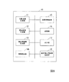
FIG. 1 is a block diagram showing an example of an image processing apparatus according to the first embodiment of the present invention.
The
投影画像生成部11は、被検体に向けて線源から照射されたX線を検出した情報に基づいて投影画像を生成する。X線は、さまざまな角度から被検体に対して照射され、投影画像生成部11は、それぞれの角度に対応する投影画像を生成する。
重合画像生成部12は、複数の投影データを重ね合わせて重合画像を生成する。投影データとは、例えば、投影画像生成部11が生成した投影画像や、投影画像に高周波を強調する処理を行った画像のことである。また、投影データを重ね合わせるとは、例えば、複数の投影データについて、画素ごとの輝度を合計し、合計した値を投影データの数で除算し平均値を算出することである。また、重合画像とは、複数の投影データの画素ごとの輝度の平均値を、対応する各画素の輝度値とする画像(以下、平均画像と呼ぶ)のことである。
補正用画像生成部13は、重合画像の各画素において、当該画素の輝度からその周囲の画素の輝度を減じた輝度を示す差分画像を生成し、さらに強調画像の符号を反転させた補正用画像を生成する。
画像補正部14は、後述する画像再構成部15が複数の投影画像に基づいて生成するCT再構成画像を、補正用画像に基づいて補正する。本実施形態において画像補正部14は、投影画像を逆投影したCT再構成画像に対して、補正用画像を逆投影して補正を行う。
The projection
The superimposed
The correction
The
画像再構成部15は、投影画像の再構成を行い、CT再構成画像を生成する。
記憶部16は、複数の投影画像や生成した補正用画像など諸々の情報を記憶する。
出力部17は、画像補正部14による補正後の再構成CT画像を画像処理装置10に接続された表示装置等に出力する。
The
The
The
図2は、投影画像と投影画像における高周波成分との関係を説明する図である。
図2(a)は、CT装置で被検体22を撮影する様子を示している。CT装置に設けられた線源21は、被検体22に対してX線を照射する。X線は、被検体22を通過し、線源21と被検体22を挟んで対向する位置に設けられた検出器23によって検出される。
図2(b)は、検出器23が検出するX線強度と検出位置との関係を示したグラフである。上述のとおり検出器23は、線源21からのX線を検出するが、被検体22がX線を吸収する度合いに応じて、検出器23が検出するX線の強度に差が生じる。図2(b)が示すように、被検体22によってX線が吸収された部分は、検出されるX線強度は低い値となる。また、被検体22にX線の吸収率が高い部分(符号24)があると、その部分に対応するX線強度の検出値はさらに低い値となる。検出器23は、検出したX線の強度に応じた電気信号を生成し、画像処理装置10に出力する。画像処理装置10では、投影画像生成部11が、取得した電気信号に基づいて、各画素の輝度をX線強度の検出値に応じた値とする投影画像を生成する。投影画像生成部11は、さまざまな角度からX線を照射したときに検出器23が検出したX線強度に基づいて、それぞれの角度に対応する投影画像を生成する。投影画像においては、各画素の輝度は、白黒の濃淡で表され、X線強度の強い部分はより黒く表示され、X線強度の弱い部分はより白く表示される。
図2(c)は、投影画像生成部11が生成した投影画像において空間高周波成分を強調した輝度と画素位置との関係を示したグラフである。図2(b)で丸印を付した部分は、高周波成分の強度が大きい部分である。図2(c)において、符号25で示したような部分は、X線の検出強度に変化が無く、投影画像上の濃淡にも変化がないため空間周波数は低く高周波成分強調輝度は小さい。一方、図2(c)において、丸を付した部分では、隣接する部分に比べ空間周波数は高く、高周波成分強調輝度は大きくなる。
FIG. 2 is a diagram for explaining the relationship between the projected image and the high-frequency component in the projected image.
FIG. 2A shows a state in which the subject 22 is imaged by the CT apparatus. A
FIG. 2B is a graph showing the relationship between the X-ray intensity detected by the
FIG. 2C is a graph showing the relationship between the luminance and the pixel position in which the spatial high-frequency component is emphasized in the projection image generated by the projection
図3は、投影画像における異常画素と強調輝度との関係を説明する図である。
図3(a)は、被検体22をある角度から撮影して得られた投影画像である。符号26は、異常画素である。このような異常画素は、例えば、検出器23のあるチャンネルが損傷していて信号が出力されないような場合に生じる。
図3(b)は、図3(a)の投影画像において符号27で示した並びの画素の高周波成分強調輝度と画素位置との関係を示したグラフである。図2を用いて説明したように被検体22と周りの空間との境界などでは、空間周波数が高くなる。さらに、図3(a)においては、異常画素26とその周囲の画素との間の濃淡に差がある為、異常画素26に対応する部分の空間周波数は、高周波となる。
図3(c)は、被検体22を図3(a)とは別のある角度から撮影して得られた投影画像の一例である。図3(d)は、図3(c)の投影画像において符号27で示した並びの画素の高周波成分強調輝度と画素位置との関係を示したグラフである。図3(d)では、図3(b)と同様に、異常画素26に対応する部分の空間周波数が高周波となる。
FIG. 3 is a diagram for explaining the relationship between abnormal pixels and enhanced luminance in a projected image.
FIG. 3A is a projection image obtained by photographing the subject 22 from a certain angle.
FIG. 3B is a graph showing the relationship between the high-frequency component enhanced luminance and the pixel position of the pixels in the arrangement indicated by
FIG. 3C is an example of a projection image obtained by imaging the subject 22 from a certain angle different from that in FIG. FIG. 3D is a graph showing the relationship between the high-frequency component emphasizing brightness and the pixel position of the pixel array indicated by
一般的にCT画像を生成するためには、再構成と呼ばれる処理を行う。CT画像の再構成では、さまざまな角度からX線を照射して生成した各投影画像について、高周波成分を強調する処理を行い、高周波強調処理を行った後の各画像を逆投影してCT再構成画像を生成する。また、逆投影とは、各投影画像をX線照射した方向に戻した画像を生成し、それらの画像を重ね合わせることである。その際、各投影画像に異常画素26のような部分があると、高周波強調処理によってその部分が強調され、逆投影後のCT画像においてリングアーチファクトが生じる原因となる。例えば検出器のチャンネルの一つが損傷している場合などは、そのチャンネルが出力するX線の強度は、周囲の検出素子が検出する強度と常に異なり且つ一定となる。すると、投影画像におけるその素子に対応する画素の輝度も、どの角度から撮影した投影画像であっても周囲の画素とは異なる輝度を示すことになり、これが逆投影してできた画像においてリングアーチファクトとなる。本実施形態では、この性質に注目し、再構築前の投影画像中でリングアーチファクトを引き起こす原因となる異常画素26を検出し、リングアーチファクトを補正する処理を行う。次に図4を用いて本実施形態によるリングアーチファクトの補正処理について説明する。
In general, in order to generate a CT image, a process called reconstruction is performed. In the reconstruction of CT images, high-frequency component enhancement processing is performed on each projection image generated by irradiating X-rays from various angles, and each image after high-frequency enhancement processing is back-projected to perform CT reconstruction. Generate a composition image. Further, the back projection is to generate an image obtained by returning each projection image in the direction of X-ray irradiation and superimpose these images. At this time, if there is a portion such as an
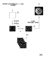
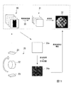
図4は、本発明の第一実施形態における画像処理装置によるリングアーチファクトの補正処理の概略図である。
符号20を付した左下の図は、CT装置によって、被検体22をX線撮影する様子を示している。CT装置は、X線の検出器23を被検体22の周りを回転させてさまざまな角度から被検体にX線を照射する。投影画像生成部11は、各角度における投影画像を生成し記憶部16に記録する。
FIG. 4 is a schematic diagram of ring artifact correction processing by the image processing apparatus according to the first embodiment of the present invention.
The lower left diagram with
符号30は、投影画像生成部11が生成した投影画像群を示している。画像再構成部15は、投影画像群30のそれぞれに対して高周波を強調する処理を行った画像(符号31)を生成し、それらの画像31を逆投影してCT再構成画像32を生成する。図4の破線で囲んだ一連の処理が再構成処理である。CT再構成画像32は、被検体22の3次元画像である。
次に本実施形態におけるリングアーチファクトの補正方法について説明する。まず、重合画像生成部12が、画像再構成の手順における高周波強調処理後の画像31のそれぞれを重ね合わせて、画素ごとに輝度の平均値を算出した平均画像(符号33)を生成する。平均画像33において、リングアーチファクトの原因となる異常画素が存在する場合は、その異常画素は、周囲の画素と異なる白黒の濃度で表示される。他の問題が無い画素では、さまざまな角度から撮影され、さまざまな輝度を有する各画像31の画素によって輝度が平均化され周囲の画素と差が小さい輝度を示すようになる。
次に、補正用画像生成部13が、平均画像33においてある当該画素の輝度からその周囲の画素の輝度を減じた輝度を示す差分画像を生成する(差分処理)。例えば、補正用画像生成部13は、差分画像の生成を次の式(1)及び式(2)に基づいて行う。
Next, a ring artifact correction method according to this embodiment will be described. First, the superimposed
Next, the correction
ここで、A(x,y)は画素位置(x,y)の平均画像の輝度、S(x,y)は平均画像を画像幅方向に平滑化した平滑化画像の画素位置(x,y)の輝度、H(x,y)は差分画像の画素位置(x,y)の輝度、Skerは平滑化する幅を表すパラメータである。
この差分処理は、リングアーチファクトの原因となる異常画素だけを抽出するために行う。次に、補正用画像生成部13は、差分処理を行った平均画像33について、符号反転処理を行って補正用画像(符号34)を生成する。
最後に画像補正部14は、補正用画像34をCT再構成画像32に逆投影する。これにより、再構成画像に生じたリングアーチファクトが補正用画像34によって打ち消され、CT再構成画像32に生じたリングアーチファクトが低減する。
Here, A (x, y) is the luminance of the average image at the pixel position (x, y), and S (x, y) is the pixel position (x, y) of the smoothed image obtained by smoothing the average image in the image width direction. ), H (x, y) is a parameter representing the luminance of the pixel position (x, y) of the difference image, and S ker is a parameter representing the width to be smoothed.
This difference process is performed to extract only abnormal pixels that cause ring artifacts. Next, the correction
Finally, the
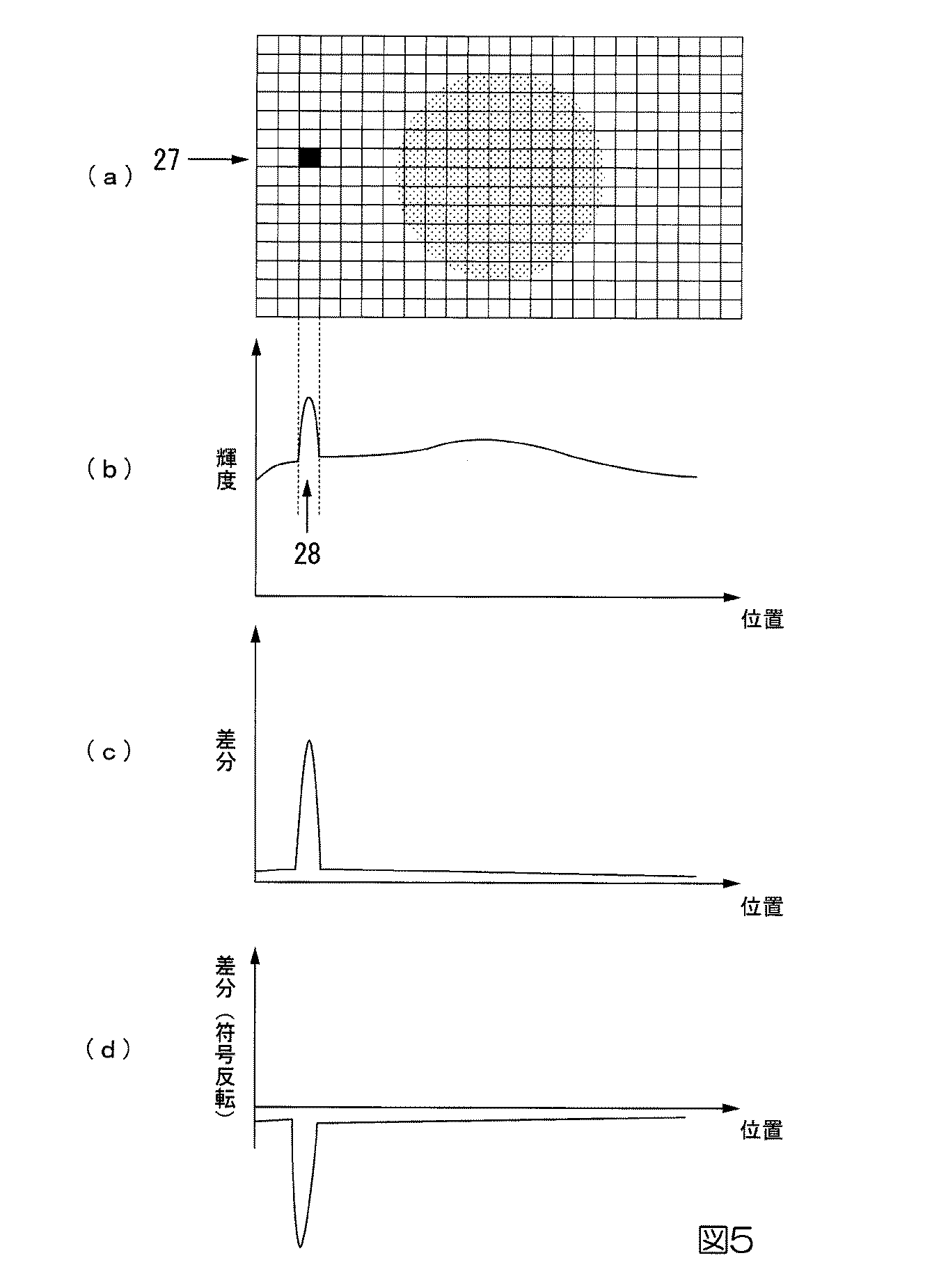
図5は、本発明の第一実施形態における補正用画像を説明する図である。
図5を用いて補正用画像34について説明する。図5(a)は、平均画像33の一例である。本実施形態の平均画像33とは、図3(a)、(c)で例示した投影画像に高周波強調処理を行った後の画像31を複数重ね合わせて各画素の輝度を平均化して生成した画像である。
図5(b)は、図5(a)において符号27で示した並びの画素の輝度の周囲との差分と画素位置との関係を示したグラフである。高周波強調処理後の画像31は、線源21および検出器23を被検体22の周りを1周させて撮影した投影画像の分だけ存在する。それらを高周波強調処理した画像を全て重ね合わせると、ある角度から撮影した投影画像に基づく画像31では輝度が高くなっている部分でも、他の角度から撮影した投影画像に基づく画像31では、必ずしも輝度が高くならないため、各画素の輝度が平均化され、周囲の画素と差が小さくなる。しかし、異常画素26については、全ての画像31において輝度が高く(または低く)なっているため全ての画像31を重ね合わせて平均化した結果もやはり輝度が高く(または低く)なる。したがって、周囲の画素との濃淡の差が大きくなり異常画素26では、周囲の画素の輝度との差が生じる。つまり、図5(b)の符号28のように平均画像33おいて周囲の画素の輝度との差がある部分には、異常画素が存在する可能性がある。
FIG. 5 is a diagram for explaining a correction image in the first embodiment of the present invention.
The
FIG. 5B is a graph showing the relationship between the difference between the luminance surroundings of the pixels in the array indicated by
図5(c)は、平均画像33に対して差分処理を行った画像における周囲の画素の輝度との差分と画素位置との関係の一例である。補正用画像生成部13は、差分処理によって周囲の画素の輝度との差を算出することで異常画素26だけを抽出する。
図5(d)は、さらに符号の反転処理を行った画像における差分と画素位置との関係の一例である。補正用画像生成部13は、平均画像33に差分処理を行った画像に対して符号反転処理を行った補正用画像34を生成する。異常画素26を抽出して、さらに符号を反転した補正用画像34を生成することで、例えば補正用画像34を任意の画像31に重ね合わせるとリングアーチファクトの原因となる異常画素26の濃淡を周囲の画素の輝度に近づけることができる。また、CT再構成画像32に対して補正用画像34を逆投影することでリングアーチファクトを低減することができる。
FIG. 5C is an example of the relationship between the difference between the brightness of the surrounding pixels in the image obtained by performing the difference process on the
FIG. 5D is an example of a relationship between a difference and a pixel position in an image that has been further subjected to sign inversion processing. The correction
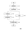
図6は、本発明の第一実施形態におけるリングアーチファクトの補正処理のフローチャートである。
図6を用いて、本実施形態のリングアーチファクト補正処理の流れについて説明する。
前提として、投影画像生成部11が、補正対象となるCT再構成画像32の元となる投影画像を生成して記憶部16に記録してあるものとする。まず、画像再構成部15が、記憶部16からさまざまな角度から撮影された投影画像群30を読み込んで取得する(ステップS11)。次に画像再構成部15は、画像再構成を行ってCT再構成画像32を生成する。具体的には、画像再構成部15は、各投影画像に対して高周波強調処理を行う(ステップS12)。画像再構成部15は、高周波強調処理を行った画像31を記憶部16へ記録する。次に画像再構成部15は、高周波強調処理を行った画像31を用いて逆投影を行う(ステップS13)。画像再構成部15は、逆投影して生成したCT再構成画像32を記憶部16に記録する。
FIG. 6 is a flowchart of the ring artifact correction process according to the first embodiment of the present invention.
The flow of the ring artifact correction process according to this embodiment will be described with reference to FIG.
As a premise, it is assumed that the projection
一方、画像再構成部15が逆投影処理を行う間、重合画像生成部12は、記憶部16から高周波強調処理後の画像31を全て読み出して、それらの画像を重ね合わせて平均化し、1枚の平均画像33を生成し(ステップS14)、記憶部16に記録する。次に補正用画像生成部13は、記憶部16から平均画像33を読み出して補正用画像34を生成する(ステップS15)。具体的には、補正用画像生成部13は、平均画像33に対して差分処理を行い、差分処理を行った画像に対して符号を反転する処理を行って補正用画像34を生成する。補正用画像生成部13は、生成した補正用画像34を記憶部16に記録する。次に、画像補正部14は、画像再構成部15が生成したCT再構成画像32と補正用画像34とを記憶部16から読み出して補正用画像34をCT再構成画像32に逆投影(ステップS16)し、リングアーチファクト補正を行った画像を生成する。
On the other hand, while the
なお、画像補正部14は、投影画像に高周波強調処理を行った画像31のそれぞれに対して、補正用画像34を重ね合わせて異常画素を補正した画像を生成し、画像再構成部15が、それら補正後の各画像を逆投影してCT再構成画像32を生成してもよい。
また、平均画像33を作成する際に、画像31のうち一部を読み出して、それらの画像を処理して補正用画像を作成してもよい。さらに、画像31のうちの異なる画像の組み合わせを複数回読み出して、複数の一時的な補正用画像を作成し、この複数の一時的な補正用画像を組み合わせて補正用画像を作成してよい。複数の一時的な補正用画像の組み合わせとは、例えば、複数の一時的な補正用画像の各画素のなかで、絶対値が小さいものを補正用画像の輝度とすることである。
また、差分処理を行う場合、ある画素の輝度が周辺画素の輝度に対して所定の閾値以上異なる場合に、当該画素を強調した差分画像を生成してもよい。その場合、例えば、補正用画像生成部13は、強調対象となる画素の輝度から周辺画素の輝度の平均値または中間値を減じた値を、差分画像における対応する画素の輝度に設定し、他の画素については、輝度をゼロに設定した差分画像を生成してもよい。
Note that the
Further, when the
Further, when performing the difference processing, when the luminance of a certain pixel is different from the luminance of the surrounding pixels by a predetermined threshold or more, a difference image in which the pixel is emphasized may be generated. In this case, for example, the correction
本実施形態によれば、リングアーチファクトの原因となる異常画素を特定し、差分処理及び符号反転処理により、異常画素26の影響を打ち消す補正用画像34を生成し、リングアーチファクトを補正する。また、この補正用画像34によってリングアーチファクトを補正するので、再構成画像に生じたリング状のアーチファクトを検出して、アーチファクトを低減する補正を行う従来の方法のように、中央部に生じた輝度点がリングアーチファクトであるか否かを判断する必要が無く、中央部に点として生じたリングアーチファクトでも補正することができる。
According to the present embodiment, an abnormal pixel that causes a ring artifact is specified, and a
<第二実施形態>
以下、本発明の第二実施形態による画像処理装置を、図7を参照して説明する。
第二実施形態における重合画像生成部12aは、高周波強調処理後の画像31ではなく、投影画像群30を重ね合わせて、平均画像33aを生成する。
補正用画像生成部13aは、平均画像33aに差分処理及び符号反転処理を行って補正用画像34aを生成する。画像補正部14aは、補正用画像34aに高周波強調処理を行った画像を用いて、CT再構成画像32に逆投影を行って補正後の画像を生成する。他の構成は、第一実施形態と同様である。
<Second embodiment>
Hereinafter, an image processing apparatus according to a second embodiment of the present invention will be described with reference to FIG.
The superimposed
The correction
図7は、本発明の第二実施形態における画像処理装置によるリングアーチファクトの補正処理の概略図である。
図7を用いて本実施形態の補正処理について説明する。第一実施形態と同様、CT装置は、さまざまな角度から被検体22にX線を照射する。画像処理装置10は、X線の検出器23が出力した電気信号に基づいて、さまざまな角度から被検体22を撮影した場合の投影画像を生成する。
次に画像再構成部15は、投影画像群30に高周波強調処理を行って、逆投影してCT再構成画像32を生成する。画像再構成部15は、CT再構成画像32を記憶部16へ記録する。
FIG. 7 is a schematic diagram of ring artifact correction processing by the image processing apparatus according to the second embodiment of the present invention.
The correction process of this embodiment will be described with reference to FIG. Similar to the first embodiment, the CT apparatus irradiates the subject 22 with X-rays from various angles. The
Next, the
次に本実施形態におけるリングアーチファクトの補正方法について説明する。まず、重合画像生成部12aが、高周波強調処理前の投影画像群30を重ね合わせて各画素の輝度を平均化した平均画像33aを生成し、平均画像33aを記憶部16へ記録する。
次に補正用画像生成部13aは、平均画像33aを記憶部16から読みだして、平均画像33aに対して、第一実施形態と同様に差分処理を行う。次に、補正用画像生成部13aは、平均画像33aに差分処理を行った画像に対して、符号反転処理を行って補正用画像34aを生成し、記憶部16へ記録する。
次に画像補正部14aは、記憶部16から補正用画像34aを読みだして、補正用画像34aに高周波強調処理を行う。この高周波強調処理は、CT画像の再構成処理における高周波強調処理(符号36)に対応するものであり、符号36の高周波強調処理と同様に行う。次に画像補正部14aは、補正用画像34aに高周波強調処理を行った画像をCT再構成画像32に逆投影する。これにより、再構成画像32に生じたリングアーチファクトを低減する。
Next, a ring artifact correction method according to this embodiment will be described. First, the superimposed
Next, the correction
Next, the image correction unit 14a reads the
本実施形態によれば、第一実施形態の効果に加え、投影画像群30から平均画像33を作成するため異常画素26の特定が容易である。
According to the present embodiment, in addition to the effects of the first embodiment, the
<第三実施形態>
以下、本発明の第三実施形態による画像処理装置を、図8〜9を参照して説明する。
本実施形態は、第一実施形態、第二実施形態と組み合わせることが可能である。
図8は、本発明の第三実施形態における画像処理装置の一例を示すブロック図である。
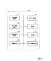
本実施形態における画像処理装置10は、統合補正用画像生成部18を備えている。図8は、第一実施形態の構成に統合補正用画像生成部18を加えた場合の構成を示している。統合補正用画像生成部18は、記憶部16に記録された過去のCT撮影時に生成した複数の補正用画像34cを読み出して、統合補正用画像35を作成する。
画像補正部14bは、統合補正用画像35を用いてCT再構成画像32のリングアーチファクト補正を行う。また、記憶部16には、過去に同じCT装置で撮影した投影画像について生成した補正用画像が少なくとも1つ以上記録されている。他の構成については第一実施形態または第二実施形態と同様である。
<Third embodiment>
Hereinafter, an image processing apparatus according to a third embodiment of the present invention will be described with reference to FIGS.
This embodiment can be combined with the first embodiment and the second embodiment.
FIG. 8 is a block diagram showing an example of an image processing apparatus according to the third embodiment of the present invention.
The
The
図9は、本発明の第三実施形態における画像処理装置によるリングアーチファクトの補正処理の概略図である。
図9を用いて、本実施形態におけるリングアーチファクトの補正処理について説明を行う。第一実施形態に本実施形態に特有の処理を加えた場合を例に説明を行う。なお、図9中、かっこの中に記載した内容は、第二実施形態と組み合わせた場合の処理を示している。
CT装置がさまざまな角度から被検体22に照射した場合のX線の検出強度に基づいて投影画像生成部11が複数の投影画像を生成し、画像再構成部15が複数の投影画像群30に高周波強調処理を行い、逆投影してCT再構成画像32を生成するのは第一実施形態と同様である。
FIG. 9 is a schematic diagram of a ring artifact correction process by the image processing apparatus according to the third embodiment of the present invention.
The ring artifact correction processing in this embodiment will be described with reference to FIG. The case where processing peculiar to this embodiment is added to the first embodiment will be described as an example. In FIG. 9, the contents described in parentheses indicate processing when combined with the second embodiment.
The projection
次に本実施形態におけるリングアーチファクトの補正方法について説明する。まず、重合画像生成部12が、投影画像群30に高周波処理を行った画像31を記憶部16から読み出して、それらの画像31を重ね合わせて平均画像33を生成し、記憶部16へ記録する。
次に補正用画像生成部13は、平均画像33を記憶部16から読みだして、平均画像33に対して、差分処理を行う。次に、補正用画像生成部13は、差分処理を行った画像に対して符号反転処理を行って補正用画像34bを生成し、記憶部16へ記録する。
Next, a ring artifact correction method according to this embodiment will be described. First, the superimposed
Next, the correction
次に統合補正用画像生成部18が、今回生成した補正用画像34bと、過去に生成した補正用画像34cとを記憶部16から読み出す。統合補正用画像生成部18は、読み出した複数の補正用画像34(34b、34c)から1つの統合補正用画像35を生成する。統合補正用画像35とは、例えば、複数の補正用画像34の平均画像、中間値画像、重み付き平均画像などである。平均画像とは、統合補正用画像35の各画素の輝度が、複数の補正用画像34における対応する各画素の輝度の平均値である画像である。中間値画像とは、統合補正用画像35の各画素の輝度が、複数の補正用画像34における対応する各画素の輝度のうち中央値である画像である。また、重み付き平均画像では、例えば、統合補正用画像35の各画素の輝度を算出するにあたり、生成した時期がより新しい補正用画像34に対してより重い重み付けを与えて輝度の平均値を算出する。統合補正用画像生成部18は、生成した統合補正用画像35を記憶部16に記録する。
次に画像補正部14は、統合補正用画像35を記憶部16から読み出してCT再構成画像32に逆投影する。これにより、CT再構成画像32に生じたリングアーチファクトを低減する。
Next, the integrated correction
Next, the
なお、第二実施形態と組み合わせる場合、重合画像生成部12aは、投影画像群30に高周波強調処理を行った画像31を記憶部16から読み出して平均画像33aを生成し、画像補正部14aは、平均画像33aに対して差分処理及び符号反転処理を行って補正用画像34aを生成する。また、記憶部16には、投影画像群30に基づいて生成した平均画像33aに対して差分処理及び符号反転処理を行って生成した補正用画像34dが少なくとも1つ格納されており、統合補正用画像生成部18は、これらの補正用画像34(34a、34d)に基づいて統合補正用画像35aを生成する。画像補正部14aは、統合補正用画像35aを記憶部16から読み出して高周波強調処理を行った画像を生成し、この画像をCT再構成画像32に逆投影する。
When combined with the second embodiment, the superimposed
本実施形態によれば、多数の補正用画像34を使用することにより、特定の撮影対象に依存しない補正用画像(統合補正用画像)が作成可能である。
なお、上記では、今回撮影した投影画像群30に基づいて生成した補正用画像34を統合補正用画像35の生成に用いる場合を例に説明を行った。しかし、今回は補正用画像34を生成する処理は行わず、予め記憶部16に記録された過去に生成した補正用画像34cだけを用いて、統合補正用画像35を生成するようにしてもよい。これにより、リングアーチファクトの補正処理を高速化することができる。
また、複数の補正用画像34から統合補正用画像35を生成せずに、例えば過去に生成した補正用画像34cのうち、最新のものを統合補正用画像35として使用してもよい。
According to the present embodiment, by using a large number of
In the above description, the case where the
Further, without generating the
<第四実施形態>
以下、本発明の第四実施形態による画像処理装置を、図10〜図11を参照して説明する。本実施形態では、補正用画像34を逆投影してリングアーチファクトを打ち消すのではなく、リングアーチファクトを形成する画素の輝度をその周囲の画素の輝度によって補間することによってリングアーチファクト補正を行う。本実施形態は、第一〜三実施形態における補正用画像34の生成方法と組み合わせることが可能であるが、特に異常画素の検出に長けた第二実施形態と組み合わせると効果的である。
図10は、本発明の第四実施形態における画像処理装置の一例を示すブロック図である。
本実施形態における画像処理装置10は、異常画素補間部19を備えている。図10は、第二実施形態の構成に異常画素補間部19を加えた場合の構成を示している。異常画素補間部19は、補正用画像34において、周囲の画素との輝度の差が所定の範囲となる画素を検出し、その検出した画素の輝度を補間する値を、当該画素の周囲の画素の輝度に基づいて決定する。画像補正部14cは、異常画素補間部19が決定した値に基づいてCT再構成画像32の異常画素に対応する画素を補正する。他の構成は第二実施形態と同様である。
<Fourth embodiment>
The image processing apparatus according to the fourth embodiment of the present invention will be described below with reference to FIGS. In the present embodiment, the ring artifact correction is performed by interpolating the luminance of the pixels forming the ring artifact by the luminance of the surrounding pixels, instead of back-projecting the
FIG. 10 is a block diagram showing an example of an image processing apparatus according to the fourth embodiment of the present invention.
The
図11は、本発明の第四実施形態における画像処理装置によるリングアーチファクトの補正処理の概略図である。
図11を用いて、本実施形態におけるリングアーチファクトの補正方法について、第二実施形態と組み合わせた場合を例に説明を行う。
CT装置がさまざまな角度から被検体22に照射したX線の検出強度に基づいて、投影画像生成部11が複数の投影画像群30を生成し、画像再構成部15がそれらの画像に高周波強調処理を行い、逆投影してCT再構成画像32を生成するのは第二実施形態と同様である。
FIG. 11 is a schematic diagram of a ring artifact correction process performed by the image processing apparatus according to the fourth embodiment of the present invention.
With reference to FIG. 11, the ring artifact correction method according to the present embodiment will be described by taking as an example a combination with the second embodiment.
The projection
一方、重合画像生成部12aは、投影画像群30を記憶部16から読み出して、投影画像群30を重ね合わせて各画素の輝度を平均化して平均画像33aを生成し、平均画像33aを記憶部16へ記録する。
次に補正用画像生成部13aは、平均画像33aを記憶部16から読みだして、差分処理を行い、符号反転処理を行って補正用画像34aを生成し、記憶部16へ記録する。
次に異常画素補間部19は、補正用画像34aを記憶部16から読みだして、補正用画像34aについて異常画素の検出を行う。例えば、異常画素補間部19は、各画素の輝度を所定の閾値と比較し、その画素の輝度が所定の範囲内であればその画素は異常画素であると判定する。次に、異常画素補間部19は、異常画素を補間するための輝度値を算出する。例えば、異常画素補間部19は、異常画素26に隣接する周囲の画素のうち異常ではない任意の画素の輝度値を補間値として決定する。あるいは、異常画素補間部19は、周囲の画素のうち異常ではない画素の濃淡の平均値や中間値を算出してその値を補間値として決定する。異常画素補間部19は、決定した補間値と異常画素群の位置情報とを画像補正部14cに出力する。画像補正部14cは、CT再構成画像32の異常画素群の輝度を補間値で補正する。これにより、CT再構成画像32のリングアーチファクトを低減することができる。
On the other hand, the superimposed
Next, the correction
Next, the abnormal
なお、異常画素の検出は、平均画像33aに対して行ってもよい。また、異常画素群も平均画像33aを逆投影して生成した画像に基づいて算出してもよい。
また。補正用画像34aや平均画像33aにおいて異常画素を検出すると、投影画像に対して高周波強調処理を行った画像31の異常画素26に対して、周囲の画素の輝度に基づいて補正する処理を行い、補正後の画像31を逆投影してCT再構成画像32を生成してもよい。
Note that the detection of abnormal pixels may be performed on the
Also. When an abnormal pixel is detected in the
上述の画像処理装置10は内部に、コンピュータシステムを有している。そして、上述した画像処理装置10における各処理の過程は、プログラムの形式でコンピュータ読み取り可能な記録媒体に記憶されており、このプログラムをコンピュータが読み出して実行することによって、上記処理が行われる。ここでコンピュータ読み取り可能な記録媒体とは、磁気ディスク、光磁気ディスク、CD−ROM、DVD−ROM、半導体メモリ等をいう。また、このコンピュータプログラムを通信回線によってコンピュータに配信し、この配信を受けたコンピュータが当該プログラムを実行するようにしてもよい。
The
また、上記プログラムは、前述した機能の一部を実現するためのものであってもよい。さらに、前述した機能をコンピュータシステムにすでに記録されているプログラムとの組み合わせで実現できるもの、いわゆる差分ファイル(差分プログラム)であってもよい。
また、画像処理装置10は、1台のコンピュータで構成されていても良いし、通信可能に接続された複数のコンピュータで構成されていてもよい。
The program may be for realizing a part of the functions described above. Furthermore, what can implement | achieve the function mentioned above in combination with the program already recorded on the computer system, what is called a difference file (difference program) may be sufficient.
Further, the
その他、本発明の趣旨を逸脱しない範囲で、上記した実施の形態における構成要素を周知の構成要素に置き換えることは適宜可能である。また、この発明の技術範囲は上記の実施形態に限られるものではなく、本発明の趣旨を逸脱しない範囲において種々の変更を加えることが可能である。 In addition, it is possible to appropriately replace the components in the above-described embodiments with known components without departing from the spirit of the present invention. The technical scope of the present invention is not limited to the above-described embodiment, and various modifications can be made without departing from the spirit of the present invention.
10・・・画像処理装置
11・・・投影画像生成部
12・・・重合画像生成部
13・・・補正用画像生成部
14・・・画像補正部
15・・・画像再構成部
16・・・記憶部
17・・・出力部
18・・・統合補正用画像生成部
19・・・異常画素補間部
21・・・線源
22・・・被検体
23・・・検出器
30・・・投影画像
31・・・画像
32・・・CT再構成画像
33・・・平均画像
34・・・補正用画像
35・・・統合補正用画像
DESCRIPTION OF
Claims (15)
前記重合画像の各画素において、当該画素と周囲の画素との輝度の差に基づいて各画素の輝度の値を決定した差分画像を生成し、さらに前記差分画像の符号を反転させた補正用画像を生成する補正用画像生成部と、
前記複数の投影画像に基づいて生成する再構成画像を、前記補正用画像に基づいて補正する画像補正部と、
を備える画像処理装置。 Obtaining projection data for each angle generated by irradiating the subject with radiation from various angles, a superimposed image generating unit that generates a superimposed image by superimposing the acquired plurality of projection data;
In each pixel of the superimposed image, a correction image is generated by generating a difference image in which the luminance value of each pixel is determined based on a difference in luminance between the pixel and surrounding pixels, and the sign of the difference image is inverted. A correction image generation unit for generating
An image correction unit that corrects a reconstructed image generated based on the plurality of projection images based on the correction image;
An image processing apparatus comprising:
請求項1に記載の画像処理装置。 The correction image generation unit generates, for each pixel of the superimposed image, a difference image having a luminance value of each pixel that is a value obtained by subtracting the luminance of the surrounding pixels from the luminance of the pixel. To generate a correction image with
The image processing apparatus according to claim 1.
請求項1に記載の画像処理装置。 The correction image generation unit generates a differential image in which the pixel is emphasized when the luminance of the pixel differs from the luminance of the surrounding pixels by a predetermined threshold or more in each pixel of the superimposed image, Further, a correction image in which the sign of the difference image is inverted is generated.
The image processing apparatus according to claim 1.
請求項1から請求項3の何れか1項に記載の画像処理装置。 The projection data is an image obtained by performing a process of emphasizing a high frequency for each of the projection images for each angle generated on the basis of information obtained by detecting radiation applied to the subject, and the superposition image generation unit Is a method of superimposing a plurality of images subjected to the process of enhancing the high frequency and generating a superimposed image in which the luminance of each pixel is averaged.
The image processing apparatus according to any one of claims 1 to 3.
請求項1から請求項3の何れか1項に記載の画像処理装置。 The projection data is a projection image for each angle generated based on information obtained by detecting radiation applied to the subject, and the superimposed image generation unit superimposes the plurality of projection images and Generate a superimposed image with the pixel brightness averaged,
The image processing apparatus according to any one of claims 1 to 3.
をさらに備え、
前記画像補正部は、前記統合補正用画像に基づいて前記再構成画像を補正する、
請求項1から請求項5の何れか1項に記載の画像処理装置。 For the integrated correction that acquires one or a plurality of correction images from the storage unit that stores the correction image generated by the correction image generation unit, and generates an integrated correction image based on the acquired correction image Image generator,
Further comprising
The image correction unit corrects the reconstructed image based on the integrated correction image;
The image processing apparatus according to any one of claims 1 to 5.
請求項6に記載の画像処理装置。 The integrated correction image generation unit calculates an average value of luminance for each pixel in the acquired plurality of correction images, and uses the calculated average value as a luminance value of each corresponding pixel. Generate images,
The image processing apparatus according to claim 6.
請求項6に記載の画像処理装置。 The integrated correction image generation unit calculates an intermediate value of luminance for each pixel in the plurality of acquired correction images, and uses the calculated intermediate value as a luminance value of each corresponding pixel. Generate images,
The image processing apparatus according to claim 6.
請求項6に記載の画像処理装置。 The integrated correction image generation unit calculates a weighted average value of luminance for each pixel in the acquired plurality of correction images, and sets the calculated weighted average value as a luminance value of each corresponding pixel. Generating the integrated correction image;
The image processing apparatus according to claim 6.
請求項1から請求項9の何れか1項に記載の画像処理装置。 The image correction unit performs correction by back projecting the correction image onto the reconstructed image.
The image processing apparatus according to any one of claims 1 to 9.
をさらに備え、
前記画像補正部は、前記投影画像に前記補正用画像を重ね合わせて補正後の投影画像を生成し、
前記画像再構成部は、前記補正後の投影画像を逆投影して再構成画像を生成する、
請求項1から請求項9の何れか1項に記載の画像処理装置。 An image reconstruction unit that backprojects the projection image to generate the reconstructed image;
Further comprising
The image correction unit generates a corrected projection image by superimposing the correction image on the projection image,
The image reconstruction unit back-projects the corrected projection image to generate a reconstructed image;
The image processing apparatus according to any one of claims 1 to 9.
をさらに備え、
前記画像補正部は、前記補正用画像に代えて前記異常画素補間部が決定した値に基づいて補正を行う、
請求項1から請求項11の何れか1項に記載の画像処理装置。 In the correction image, a pixel whose luminance difference with surrounding pixels falls within a predetermined range is detected, and a value for interpolating the luminance of the detected pixel is determined based on the luminance of the surrounding pixels of the pixel. Abnormal pixel interpolation unit,
Further comprising
The image correction unit performs correction based on a value determined by the abnormal pixel interpolation unit instead of the correction image.
The image processing apparatus according to any one of claims 1 to 11.
前記重合画像の各画素において、当該画素と周囲の画素との輝度の差に基づいて各画素の輝度の値を決定した差分画像を生成し、さらに前記差分画像の符号を反転させた補正用画像を生成し、
前記複数の投影画像に基づいて生成する再構成画像を、前記補正用画像に基づいて補正する、
画像処理方法。 Obtaining projection data for each angle generated by irradiating a subject with radiation from various angles, and generating a superimposed image by superimposing the plurality of obtained projection data,
In each pixel of the superimposed image, a correction image is generated by generating a difference image in which the luminance value of each pixel is determined based on a difference in luminance between the pixel and surrounding pixels, and the sign of the difference image is inverted. Produces
Correcting a reconstructed image generated based on the plurality of projection images based on the correction image;
Image processing method.
さまざまな角度から放射線を被検体に照射して生成した前記角度ごとの投影データを取得し、前記取得した複数の投影データを重ね合わせて重合画像を生成する手段、
前記重合画像の各画素において、当該画素と周囲の画素との輝度の差に基づいて各画素の輝度の値を決定した差分画像を生成し、さらに前記差分画像の符号を反転させた補正用画像を生成する手段、
前記複数の投影画像に基づいて生成する再構成画像を、前記補正用画像に基づいて補正する手段、
として機能させるためのプログラム。 The computer of the image processing device
Means for acquiring projection data for each angle generated by irradiating a subject with radiation from various angles, and generating a superimposed image by superimposing the plurality of acquired projection data;
In each pixel of the superimposed image, a correction image is generated by generating a difference image in which the luminance value of each pixel is determined based on a difference in luminance between the pixel and surrounding pixels, and the sign of the difference image is inverted. Means for generating,
Means for correcting a reconstructed image generated based on the plurality of projection images based on the correction image;
Program to function as.
Priority Applications (1)
| Application Number | Priority Date | Filing Date | Title |
|---|---|---|---|
| JP2014248937A JP2016106938A (en) | 2014-12-09 | 2014-12-09 | Image processing device, ct device, image processing method, and program |
Applications Claiming Priority (1)
| Application Number | Priority Date | Filing Date | Title |
|---|---|---|---|
| JP2014248937A JP2016106938A (en) | 2014-12-09 | 2014-12-09 | Image processing device, ct device, image processing method, and program |
Publications (1)
| Publication Number | Publication Date |
|---|---|
| JP2016106938A true JP2016106938A (en) | 2016-06-20 |
Family
ID=56122518
Family Applications (1)
| Application Number | Title | Priority Date | Filing Date |
|---|---|---|---|
| JP2014248937A Pending JP2016106938A (en) | 2014-12-09 | 2014-12-09 | Image processing device, ct device, image processing method, and program |
Country Status (1)
| Country | Link |
|---|---|
| JP (1) | JP2016106938A (en) |
Cited By (2)
| Publication number | Priority date | Publication date | Assignee | Title |
|---|---|---|---|---|
| CN109893149A (en) * | 2017-12-11 | 2019-06-18 | 株式会社岛津制作所 | Fluoroscopy |
| CN115439353A (en) * | 2022-08-23 | 2022-12-06 | 南方医科大学南方医院 | CT image ring artifact correction method, system and storage medium |
-
2014
- 2014-12-09 JP JP2014248937A patent/JP2016106938A/en active Pending
Cited By (3)
| Publication number | Priority date | Publication date | Assignee | Title |
|---|---|---|---|---|
| CN109893149A (en) * | 2017-12-11 | 2019-06-18 | 株式会社岛津制作所 | Fluoroscopy |
| CN115439353A (en) * | 2022-08-23 | 2022-12-06 | 南方医科大学南方医院 | CT image ring artifact correction method, system and storage medium |
| CN115439353B (en) * | 2022-08-23 | 2023-11-07 | 南方医科大学南方医院 | CT image ring artifact correction method, system and storage medium |
Similar Documents
| Publication | Publication Date | Title |
|---|---|---|
| CN106600568B (en) | A kind of low-dose CT image de-noising method and device | |
| JP6416582B2 (en) | Method and apparatus for metal artifact removal in medical images | |
| KR101389841B1 (en) | Panorama image data providing method and apparatus | |
| Funama et al. | A newly-developed metal artifact reduction algorithm improves the visibility of oral cavity lesions on 320-MDCT volume scans | |
| CN111223156B (en) | Metal artifact eliminating method for dental cone beam CT system | |
| US20080304617A1 (en) | Method for generating a 3D reconstruction of a body | |
| JP6214226B2 (en) | Image processing apparatus, tomography apparatus, image processing method and program | |
| JP2010125332A (en) | Sequential projection for forming calculator type tomographic image in optional spectrum | |
| Chang et al. | Metal artifact reduction algorithm for single energy and dual energy CT scans | |
| JP2014503331A5 (en) | ||
| JPWO2009157217A1 (en) | Image correction processing apparatus and image correction processing method | |
| US20170172534A1 (en) | Thoracic imaging for cone beam computed tomography | |
| JP2011255033A (en) | Radiation image region-extracting apparatus, radiation image region-extracting program, and radiographic apparatus | |
| US20220414832A1 (en) | X-ray imaging restoration using deep learning algorithms | |
| KR101065838B1 (en) | Sinogram inpainting apparatus and method | |
| CN110574073A (en) | Detection and/or correction of residual iodine artifacts in spectral Computed Tomography (CT) imaging | |
| CN109389577B (en) | X-ray image processing method and system, and computer storage medium | |
| WO2014136415A1 (en) | Body-movement detection device and method | |
| JP6945462B2 (en) | Image processing device, image processing method, and image processing program | |
| CN107635468B (en) | Device and method for reconstructing medical images | |
| JP2016106938A (en) | Image processing device, ct device, image processing method, and program | |
| US20200240934A1 (en) | Tomography apparatus and controlling method for the same | |
| JP2004528100A (en) | CT image reconstruction | |
| JP3669789B2 (en) | Abnormal shadow candidate detection method and apparatus | |
| JP2006239049A (en) | X-ray ct apparatus |
Legal Events
| Date | Code | Title | Description |
|---|---|---|---|
| A711 | Notification of change in applicant |
Free format text: JAPANESE INTERMEDIATE CODE: A711 Effective date: 20170424 |
|
| A521 | Request for written amendment filed |
Free format text: JAPANESE INTERMEDIATE CODE: A821 Effective date: 20170424 |


