JP2016103777A - Imaging device, and control method and program therefor - Google Patents
Imaging device, and control method and program therefor Download PDFInfo
- Publication number
- JP2016103777A JP2016103777A JP2014241866A JP2014241866A JP2016103777A JP 2016103777 A JP2016103777 A JP 2016103777A JP 2014241866 A JP2014241866 A JP 2014241866A JP 2014241866 A JP2014241866 A JP 2014241866A JP 2016103777 A JP2016103777 A JP 2016103777A
- Authority
- JP
- Japan
- Prior art keywords
- range
- display
- crop
- displayed
- grid lines
- Prior art date
- Legal status (The legal status is an assumption and is not a legal conclusion. Google has not performed a legal analysis and makes no representation as to the accuracy of the status listed.)
- Granted
Links
Images


Classifications
-
- H—ELECTRICITY
- H04—ELECTRIC COMMUNICATION TECHNIQUE
- H04N—PICTORIAL COMMUNICATION, e.g. TELEVISION
- H04N23/00—Cameras or camera modules comprising electronic image sensors; Control thereof
- H04N23/50—Constructional details
-
- H—ELECTRICITY
- H04—ELECTRIC COMMUNICATION TECHNIQUE
- H04N—PICTORIAL COMMUNICATION, e.g. TELEVISION
- H04N23/00—Cameras or camera modules comprising electronic image sensors; Control thereof
- H04N23/60—Control of cameras or camera modules
- H04N23/63—Control of cameras or camera modules by using electronic viewfinders
- H04N23/633—Control of cameras or camera modules by using electronic viewfinders for displaying additional information relating to control or operation of the camera
- H04N23/635—Region indicators; Field of view indicators
-
- H—ELECTRICITY
- H04—ELECTRIC COMMUNICATION TECHNIQUE
- H04N—PICTORIAL COMMUNICATION, e.g. TELEVISION
- H04N23/00—Cameras or camera modules comprising electronic image sensors; Control thereof
- H04N23/60—Control of cameras or camera modules
- H04N23/667—Camera operation mode switching, e.g. between still and video, sport and normal or high- and low-resolution modes
-
- H—ELECTRICITY
- H04—ELECTRIC COMMUNICATION TECHNIQUE
- H04N—PICTORIAL COMMUNICATION, e.g. TELEVISION
- H04N2101/00—Still video cameras
-
- H—ELECTRICITY
- H04—ELECTRIC COMMUNICATION TECHNIQUE
- H04N—PICTORIAL COMMUNICATION, e.g. TELEVISION
- H04N25/00—Circuitry of solid-state image sensors [SSIS]; Control thereof
- H04N25/40—Extracting pixel data from image sensors by controlling scanning circuits, e.g. by modifying the number of pixels sampled or to be sampled
- H04N25/44—Extracting pixel data from image sensors by controlling scanning circuits, e.g. by modifying the number of pixels sampled or to be sampled by partially reading an SSIS array
- H04N25/443—Extracting pixel data from image sensors by controlling scanning circuits, e.g. by modifying the number of pixels sampled or to be sampled by partially reading an SSIS array by reading pixels from selected 2D regions of the array, e.g. for windowing or digital zooming
Abstract
Description
本発明は、電子スチルカメラ等の撮像装置、その制御方法、プログラム及びコンピュータ読み取り可能な記憶媒体に関する。 The present invention relates to an imaging apparatus such as an electronic still camera, a control method thereof, a program, and a computer-readable storage medium.
近年、デジタルカメラの高画素化が進み、クロップ撮影が可能な機種が増えつつある。クロップ撮影では、撮像素子の一部分のみを写真として切りだすため、一本のレンズで望遠効果が得られることに加え、データ量も減らすことができるメリットがある。クロップ撮影が可能なデジタルカメラでは、クロップ範囲をファインダ内に表示し、撮影される範囲をユーザに示す仕様になっているのが一般的である。 In recent years, as the number of pixels of digital cameras has increased, the number of models capable of crop photography is increasing. In crop photography, since only a part of the image sensor is cut out as a photograph, a telephoto effect can be obtained with a single lens, and there is an advantage that the amount of data can be reduced. In general, a digital camera capable of crop photography has a specification in which a crop range is displayed in a finder and a photographed range is indicated to a user.
クロップ撮影やアスペクト比の表示に関する参考文献として、例えば特許文献1には、視野の大きさを変化可能なファインダにおいて、視野の変化に応じて、ファインダ内表示部を移動させる技術が開示されている。また、例えば特許文献2には、像画像を設定アスペクト比にトリミングして記録するトリミング記録モードと、撮像画像を記録しつつ、アスペクト比情報を記録画像のヘッダに記録するアスペクト比付加記録モードとを選択でき、前記トリミング記録モードでは、前記撮像画像のうちの、前記設定アスペクト比に含まれる範囲を表示し、前記アスペクト比付加記録モードでは、前記撮像画像に重ねて、前記設定アスペクト比を示すアスペクト比表示を表示する技術が開示されている。
As a reference for crop photography and aspect ratio display, for example,
クロップ範囲を枠で表示し、且つ、方眼線の液晶表示を重ねて表示した場合、クロップ範囲外にまで方眼の線が伸びてしまい、クロップ範囲が分かりづらくなる問題がある。先行技術文献のようにファインダ内表示部を移動させても、クロップ範囲外に方眼線が表示されたままだと分かりづらさは解消できない。また、記録モードに応じて表示の切り替えの判定を行っても、撮影前に分かりづらければ、やはり問題は解決されない。 When the cropping range is displayed with a frame and the grid line liquid crystal display is overlaid, the grid line extends beyond the cropping range, which makes it difficult to understand the cropping range. Even if the in-finder display portion is moved as in the prior art document, it is difficult to solve the difficulty of understanding if the grid lines are still displayed outside the cropping range. Even if the display switching is determined according to the recording mode, the problem is still not solved if it is difficult to understand before shooting.
本発明は上記のような点に鑑みてなされたものであり、クロップ範囲と方眼線との両方を分かり易く表示できるようにすることを目的とする。 The present invention has been made in view of the above points, and an object of the present invention is to enable easy display of both a cropping range and a grid line.
本発明の撮像装置は、表示装置にクロップ範囲と方眼線とを表示することのできる撮像装置であって、方眼線は複数のセグメントにより表示され、クロップ範囲と方眼線との両方を表示するときに、クロップ範囲を表示するとともに、クロップ範囲内だけで方眼線を表示するように前記セグメントの点灯及び消灯を制御する制御手段を備えたことを特徴とする。 The imaging device of the present invention is an imaging device capable of displaying a crop range and grid lines on a display device, and the grid lines are displayed by a plurality of segments, and both the crop range and grid lines are displayed. And a control means for controlling lighting and extinguishing of the segments so as to display the cropping range and display grid lines only within the cropping range.
本発明によれば、クロップ範囲と方眼線との両方を分かり易く表示することが可能となる。 According to the present invention, it is possible to display both the cropping range and the grid line in an easy-to-understand manner.
以下、添付図面を参照して、本発明の好適な実施形態について説明する。
図1は、実施形態に係る撮像装置であるデジタルカメラの構成を示すブロック図である。デジタルカメラ200にはレンズユニット100が装着される。なお、本実施形態ではレンズユニット100が着脱自在の構成を説明するが、デジタルカメラにレンズが一体化されたものでもよい。
Preferred embodiments of the present invention will be described below with reference to the accompanying drawings.
FIG. 1 is a block diagram illustrating a configuration of a digital camera that is an imaging apparatus according to the embodiment. The
レンズユニット100において、レンズ5は通常、複数枚のレンズから構成されるが、ここでは簡略して一枚のレンズのみで示している。
通信端子6は、レンズユニット100がデジタルカメラ200側と通信を行うための通信端子であり、通信端子10は、デジタルカメラ200がレンズユニット100側と通信を行うための通信端子である。レンズユニット100は、通信端子6、10を介してデジタルカメラ200側のマイクロコンピュータ40と通信し、内部のレンズシステム制御回路4によって絞り駆動回路2を介して絞り1の制御を行い、AF駆動回路3を介してレンズ5の位置を変位させることで焦点を合わせる。マイクロコンピュータ40は、通信端子6、10を介して、レンズユニット100の開放絞り値及び最小絞り値を取得する。
In the
The communication terminal 6 is a communication terminal for the
デジタルカメラ200において、マイクロコンピュータ40は、デジタルカメラ200に含まれる各部を制御する。マイクロコンピュータ40は、不揮発性メモリ38に記録されたプログラムを、揮発性メモリ39をワークメモリとして展開し、実行することで後述する各種処理を実行する。
AEセンサ15は、レンズユニット100を通した被写体の輝度を測光する。
AFセンサ11は、マイクロコンピュータ40にデフォーカス量情報を出力する。マイクロコンピュータ40は、それに基づいてレンズユニット100を制御する。
In the
The
The
クイックリターンミラー12は、露光の際にマイクロコンピュータ40から指示されて、不図示のアクチュエータによりアップダウンされる。撮影者は、ペンタプリズム14とファインダ16を介してフォーカシングスクリーン13を観察することで、レンズユニット100を通して得た被写体の光学像の焦点や構図の確認が可能となる。
フォーカルプレーンシャッタ17は、マイクロコンピュータ40の制御で撮像素子20の露光時間を自由に制御できる。マイクロコンピュータ40はシャッタ制御回路36を介してフォーカルプレーンシャッタ17を制御する。
光学フィルタ18は一般的にローパスフィルタ等から構成され、フォーカルプレーンシャッタ17より入ってくる光の高周波成分をカットして、撮像素子20に被写体像を導光する。
撮像素子20は、一般的にCCDやCMOS等が用いられる撮像素子であり、レンズユニット100を通して撮像素子20上に結像された被写体象を光電変換して電気信号として取り込む。マイクロコンピュータ40は、タイミング制御回路32を介して撮像素子20の駆動タイミングを制御する。
The
The focal plane shutter 17 can freely control the exposure time of the
The
The
AMP回路21は、取り込まれた電気信号に対して、設定されている撮影感度に応じたゲインで撮影信号を増幅する。
A/D変換回路22は、撮像素子20によって電気信号に変換されたアナログ信号をデジタル信号に変換する。
画像処理回路23は、A/D変換回路22によってデジタル信号に変換された画像データに対して、フィルタ処理、色変換処理、ガンマー/ニー処理を行い、メモリコントローラ27に出力する。また、画像処理回路23は、D/A変換回路も内蔵しており、A/D変換回路22によってデジタル信号に変換された画像データやメモリコントローラ27により入力される画像データをアナログ信号に変換して液晶駆動回路24を介して液晶表示部25に出力する。これらの画像処理回路23による画像処理及び表示処理は、マイクロコンピュータ40により切り替えられる。また、マイクロコンピュータ40は、撮影画像のカラーバランス情報に基づいてホワイトバランス調整を行う。液晶表示部25は、画像を表示するための背面モニタである。画像を表示するディスプレイであれば液晶方式に限らず、有機EL等、他の方式のディスプレイであってもよい。
The
The A /
The
メモリコントローラ27は、画像処理回路23から入力された未処理の画像データをバッファメモリ26に格納したり、画像処理済みの画像データを記録媒体28に格納したりする。また、メモリコントローラ27は、逆にバッファメモリ26や記録媒体28から画像データを取り込んで画像処理回路23に出力する。また、メモリコントローラ27は、外部インタフェース29を介して送られてくる画像データを記録媒体28に格納したり、逆に記録媒体28に格納されている画像データを外部インタフェース29を介して外部に出力したりする。外部インタフェースとしては、USB、IEEE、HDMI(登録商標)等のインタフェースが例として挙げられる。記録媒体28は、メモリカード等の着脱可能な記録媒体である。ただし、内蔵メモリであってもよい。
The
電源制御回路35は、AC電源部30又は2次電池部31より供給され電源を制御する。電源制御回路35は、マイクロコンピュータ40から指示を受けて電源のオンオフを行う。また、電源制御回路35は、電源状態検知回路34により検知された現在の電源状態の情報や電源種類検知回路33により検知された現在の電源の種類の情報をマイクロコンピュータ40に通知する。
光学フィルタ振動制御回路37は、光学フィルタ18に接続されている圧電素子19を振動させる。マイクロコンピュータ40は、振動の振幅、振動時間、振動の軸方向をそれぞれ所定の値で圧電素子19を振動させるように指示する。
不揮発性メモリ38は、ユーザが任意に設定したシャッタ速度、絞り値、撮影感度等の設定値やその他の各種データを撮像装置に電源が入れられていない状態でも保存することができる。
揮発性メモリ39は、撮像装置の内部状態や着脱可能な記録媒体28の情報等、一時的に記憶しておきたいデータを保存しておく。
The power
The optical filter
The
The
ファインダ内液晶表示部41は、ファインダ内液晶駆動回路42を介して、現在オートフォーカスが行われている測距点を示す枠や、クロップマスク表示、クロップ範囲を示す枠、方眼線等を表示する。
ファインダ外液晶表示部43は、ファインダ外液晶駆動回路44を介して、シャッタ速度や絞りをはじめとするカメラの様々な設定値を表示する。
操作部70は、ユーザからの操作を受け付ける入力部としての各種操作部材である。操作部70には、後述する図2に示す各種操作部材が含まれる。
The in-finder liquid
The outside-finder liquid
The
図2(a)は、デジタルカメラ200の正面側の外観を示す図であり、図2(b)は、デジタルカメラ200の背面側からの外観を示す図である。図1と共通する部分は、同じ符号を付す。
レリーズ釦201は、撮影の準備指示及び撮影指示を行うための操作部材である。レリーズ釦201を半押しすることで、被写体の輝度の測定や合焦を行う。また、レリーズ釦201を全押しすることで、シャッタが切られ画像の撮影が行われる。
メイン電子ダイヤル202は、回転操作部材であり、ユーザはメイン電子ダイヤル202を回すことでシャッタ速度や絞り等の設定値の設定を行ったり、拡大モードでの拡大倍率の微調整を行ったりする。
サブ電子ダイヤル203は、回転操作部材であり、ユーザはサブ電子ダイヤル203を回すことで絞りや露出補正等の設定値の設定を行ったり、画像表示状態での画像の1枚送り操作を行ったりする。
電源スイッチ204は、電源のON及びOFFを行うための操作部材である。
プロテクト釦205は、撮像装置内外の記録媒体に保存されている画像に対して、プロテクトやレーティングといった処理を施すための操作部材である。
メニュー釦206は、各種設定画面を液晶表示部25に表示させるための操作部材である。
削除釦207は、撮像装置内外の記録媒体に保存されている画像に対して、削除を指示するための操作部材である。
拡大モード釦208は、再生状態において、拡大モードへの遷移指示(拡大モードの開始指示)、及び拡大モードから抜ける指示(拡大モードの終了指示)を行うための操作部材である。
再生指示釦209は、撮像装置内外の記録媒体に保存されている画像を液晶表示部25に表示させるための操作部材である。
測距点選択釦210は、オートフォーカスの開始ポイントである測距点を選択するモードに入るための操作部材である。
マルチコントローラ211は、オートフォーカスの開始ポイントである測距点の設定を行ったり、拡大画像表示状態において、拡大枠(拡大している範囲)の移動を行ったりするための複数方向に操作可能な操作部材である。
WB/測光モード選択釦213は、WB(ホワイトバランス)と測光モードを選択するモードに入るための操作部材である。撮像装置がこのモードに入っているときに、メイン電子ダイヤル202を操作することで測光モードの変更が行われ、サブ電子ダイヤル203を操作することでWBモードの変更が行われる。
FIG. 2A is a diagram illustrating an appearance of the front side of the
The
The main
The sub
The
The
The
The
The
The
The distance measuring
The multi-controller 211 can be operated in a plurality of directions for setting a distance measuring point that is a start point of autofocus or moving an enlarged frame (enlarged range) in an enlarged image display state. It is an operation member.
The WB / photometry
以下、クロップ範囲、方眼線を設定したときの表示手法について説明する。本実施形態では、クロップ範囲設定が無しのとき、クロップ範囲をAPSHサイズとしたとき、クロップ範囲をAPSCサイズとしたときの表示について説明する。
図3は、実施形態に係るデジタルカメラ200の処理動作を示すフローチャートである。
ステップS100で、マイクロコンピュータ40は、電源スイッチ204が電源ONになっているか否か判定する。電源ONになっていればステップS101に進み、電源ONになっていなければ本処理を終了する。
Hereinafter, a display method when a crop range and grid lines are set will be described. In this embodiment, a display when the crop range is not set, the crop range is set to APSH size, and the crop range is set to APSC size will be described.
FIG. 3 is a flowchart illustrating the processing operation of the
In step S100, the
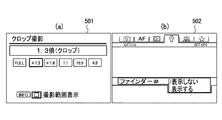
ステップS101で、マイクロコンピュータ40は、不揮発性メモリ38に設定されているクロップ範囲の設定値を取得する。ユーザは、図5(a)に示すGUI画面501上でクロップ範囲の設定を行い、不揮発性メモリ38に保存することができる。
ステップS102で、マイクロコンピュータ40は、ステップS101において取得したクロップ範囲設定よりクロップ範囲が設定されているか否かを判定する。クロップ範囲が設定されていればステップS103に進み、クロップ範囲が設定されていなければステップS104に進む。
ステップS103で、マイクロコンピュータ40は、クロップ範囲を表示するようにファインダ内液晶駆動回路42を制御する。ステップS101において取得したクロップ範囲がAPSHであれば、ファインダ16内には、図6(a)に示すように、APSHのクロップ範囲が枠601で表示される。図8B(f)に、APSHサイズのクロップ範囲の枠を表示するためのセグメントを示す。また、ステップS101において取得したクロップ範囲がAPSCであれば、ファインダ16内には、図6(b)に示すように、APSCのクロップ範囲が枠602で表示される。図8B(g)に、APSCサイズのクロップ範囲の枠を表示するためのセグメントを示す。
In step S <b> 101, the
In step S102, the
In step S103, the
ステップS104で、マイクロコンピュータ40は、不揮発性メモリ38に設定されている方眼線表示設定の設定値を取得する。方眼線表示設定は、方眼線をファインダ16内に表示するか否かを設定する設定値である。ユーザは、図5(b)に示すGUI画面502上で方眼線表示設定を行い、不揮発性メモリ38に保存することができる。
ステップS105で、マイクロコンピュータ40は、ステップS104において取得した方眼線表示設定が、方眼線を表示する設定になっているか否かを判定する。方眼線を表示する設定になっていればステップS106に進み、方眼線を表示する設定になっていなければ本処理を終了する。
ステップS106で、マイクロコンピュータ40は、方眼線表示処理を行う。この方眼線表示処理の詳細は図4を用いて後述する。
In step S <b> 104, the
In step S105, the
In step S106, the
次に、ステップS106の方眼線表示処理の詳細を説明する。
図4は、ステップS106の方眼線表示処理の詳細を示すフローチャートである。
ステップS200で、マイクロコンピュータ40は、ステップS101において取得したクロップ範囲設定よりクロップ範囲が設定されているか否かを判定する。クロップ範囲が設定されていればステップS201に進み、クロップ範囲が設定されていなければステップS202に進む。
Next, the details of the grid line display process in step S106 will be described.
FIG. 4 is a flowchart showing details of the grid line display processing in step S106.
In step S200, the
ステップS201で、マイクロコンピュータ40は、設定されているクロップ範囲内だけで方眼線を表示するようにファインダ内液晶駆動回路42を制御する。
ここで、図8A(a)〜(f)及び図8B(a)〜(e)に、方眼線を表示するためのセグメントの配置を示す。
図7(b)に、ステップS101において取得したクロップ範囲設定がAPSHである場合の表示例を示す。方眼線を表示するために、マイクロコンピュータ40は、図8A(a)、(b)、(d)、(e)、図8B(a)、(c)、(f)のセグメントを点灯するように、ファインダ内液晶駆動回路42を制御する。
また、図7(d)に、ステップS101において取得したクロップ範囲設定がAPSCである場合の表示例を示す。方眼線を表示するために、マイクロコンピュータ40は、図8A(a)、(d)、図8B(g)のセグメントを点灯するように、ファインダ内液晶駆動回路42を制御する。ここで、図7(d)の表示では、クロップ範囲の枠と方眼線とが近接して、見えづらくなっていることが分かる。
In step S201, the
Here, FIG. 8A (a) to (f) and FIG. 8B (a) to (e) show the arrangement of segments for displaying grid lines.
FIG. 7B shows a display example when the crop range setting acquired in step S101 is APSH. In order to display grid lines, the
FIG. 7D shows a display example when the crop range setting acquired in step S101 is APSC. In order to display grid lines, the
ステップS202で、マイクロコンピュータ40は、撮像範囲全体まで方眼線を表示するようにファインダ内液晶駆動回路42を制御する。
図7(a)に、撮像範囲全体まで方眼線を表示した例を示す。方眼線を表示するために、マイクロコンピュータ40は、方眼線を表示するための全セグメント、すなわち図8A(a)、(b)、(c)、(d)、(e)、(f)、図8B(a)、(b)、(c)、(d)、(e)のセグメントを点灯するように、ファインダ内液晶駆動回路42を制御する。
In step S202, the
FIG. 7A shows an example in which grid lines are displayed up to the entire imaging range. In order to display grid lines, the
ステップS203で、マイクロコンピュータ40は、ステップS101において取得したクロップ範囲の枠と方眼線とが近接しているか否かを判定する。近接していればステップS204に進み、近接していなければ本処理を終了する。
ステップS204で、マイクロコンピュータ40は、クロップ範囲の枠に近接している方眼線のセグメントを消灯するようにファインダ内液晶駆動回路42を制御する。図7(d)に示すように、クロップ範囲の枠と方眼線とが近接している状態から、マイクロコンピュータ40は、図8A(d)のセグメントを消灯するようにファインダ内液晶駆動回路42を制御する。これにより、図7(c)に示すように、クロップ範囲の枠と近接する方眼線のセグメントが消去され、すなわち方眼線を構成する線のうち、クロップ範囲に近接する線が表示されなくなり、クロップ範囲と方眼線との両方を分かり易く表示することができる。
In step S203, the
In step S204, the
なお、図3、図4で説明した制御は1つのハードウェアが行ってもよいし、複数のハードウェアが処理を分担することで、装置全体の制御を行ってもよい。
以上、本発明の好ましい実施形態について説明したが、本発明はこれら特定の実施形態に限られるものではなく、この発明の要旨を逸脱しない範囲の様々な形態も本発明に含まれる。さらに、上述した各実施形態は本発明の一実施形態を示すものにすぎず、各実施形態を適宜組み合わせることも可能である。
本発明は、上述した実施形態においては、本発明をデジタルカメラに適用した場合を例にして説明したが、これはこの例に限定されず、表示装置にクロップ範囲と方眼線とを表示することのできる撮像装置であれば適用可能である。
Note that the control described in FIGS. 3 and 4 may be performed by one piece of hardware, or the entire apparatus may be controlled by a plurality of pieces of hardware sharing the processing.
As mentioned above, although preferable embodiment of this invention was described, this invention is not limited to these specific embodiment, Various forms of the range which does not deviate from the summary of this invention are also contained in this invention. Furthermore, each embodiment mentioned above shows only one embodiment of this invention, and it is also possible to combine each embodiment suitably.
In the above-described embodiment, the present invention has been described by taking the case where the present invention is applied to a digital camera as an example. However, this is not limited to this example, and a cropping range and grid lines are displayed on a display device. Any imaging device capable of performing the above can be applied.
(その他の実施例)
本発明は、上述の実施形態の1以上の機能を実現するプログラムを、ネットワーク又は記憶媒体を介してシステム又は装置に供給し、そのシステム又は装置のコンピュータにおける1つ以上のプロセッサーがプログラムを読出し実行する処理でも実現可能である。また、1以上の機能を実現する回路(例えば、ASIC)によっても実現可能である。
(Other examples)
The present invention supplies a program that realizes one or more functions of the above-described embodiments to a system or apparatus via a network or a storage medium, and one or more processors in a computer of the system or apparatus read and execute the program This process can be realized. It can also be realized by a circuit (for example, ASIC) that realizes one or more functions.
200:デジタルカメラ、16:ファインダ、20:撮像素子、38:不揮発性メモリ、39:揮発性メモリ、40:マイクロコンピュータ、42:ファインダ内液晶駆動回路 200: Digital camera, 16: Finder, 20: Image sensor, 38: Non-volatile memory, 39: Volatile memory, 40: Microcomputer, 42: Liquid crystal drive circuit in the finder
Claims (7)
方眼線は複数のセグメントにより表示され、
クロップ範囲と方眼線との両方を表示するときに、クロップ範囲を表示するとともに、クロップ範囲内だけで方眼線を表示するように前記セグメントの点灯及び消灯を制御する制御手段を備えたことを特徴とする撮像装置。 An imaging device capable of displaying a crop range and grid lines on a display device,
Grid lines are displayed by multiple segments,
When displaying both the cropping range and the grid line, control means is provided for controlling the turning on and off of the segment so that the cropping range is displayed and the grid line is displayed only within the cropping range. An imaging device.
クロップ範囲と方眼線との両方を表示するときに、クロップ範囲を表示するとともに、クロップ範囲内だけで方眼線を表示するように、方眼線を表示するための複数のセグメントの点灯及び消灯を制御するステップを有することを特徴とする撮像装置の制御方法。 A method for controlling an imaging apparatus capable of displaying a crop range and grid lines on a display device,
When displaying both the cropping range and grid lines, the cropping range is displayed, and the lighting and extinction of multiple segments for displaying grid lines is controlled so that the grid lines are displayed only within the cropping range. And a step of controlling the imaging apparatus.
Priority Applications (3)
| Application Number | Priority Date | Filing Date | Title |
|---|---|---|---|
| JP2014241866A JP6448330B2 (en) | 2014-11-28 | 2014-11-28 | Imaging apparatus, control method thereof, and program |
| US14/951,259 US10104295B2 (en) | 2014-11-28 | 2015-11-24 | Image pickup apparatus and control method for image pickup apparatus with display of crop area and grid lines |
| CN201510848307.1A CN105657222B (en) | 2014-11-28 | 2015-11-27 | The control method of photographic device and photographic device |
Applications Claiming Priority (1)
| Application Number | Priority Date | Filing Date | Title |
|---|---|---|---|
| JP2014241866A JP6448330B2 (en) | 2014-11-28 | 2014-11-28 | Imaging apparatus, control method thereof, and program |
Publications (3)
| Publication Number | Publication Date |
|---|---|
| JP2016103777A true JP2016103777A (en) | 2016-06-02 |
| JP2016103777A5 JP2016103777A5 (en) | 2017-12-21 |
| JP6448330B2 JP6448330B2 (en) | 2019-01-09 |
Family
ID=56079995
Family Applications (1)
| Application Number | Title | Priority Date | Filing Date |
|---|---|---|---|
| JP2014241866A Active JP6448330B2 (en) | 2014-11-28 | 2014-11-28 | Imaging apparatus, control method thereof, and program |
Country Status (3)
| Country | Link |
|---|---|
| US (1) | US10104295B2 (en) |
| JP (1) | JP6448330B2 (en) |
| CN (1) | CN105657222B (en) |
Families Citing this family (5)
| Publication number | Priority date | Publication date | Assignee | Title |
|---|---|---|---|---|
| DE102016104381A1 (en) * | 2016-03-10 | 2017-09-14 | Osram Opto Semiconductors Gmbh | Optoelectronic lighting device, method for illuminating a scene, camera and mobile terminal |
| DE112017004244B4 (en) * | 2016-09-27 | 2021-06-10 | Fujifilm Corporation | Camera, display control method of the camera, and display control program of the camera |
| JP2019176023A (en) * | 2018-03-28 | 2019-10-10 | 京セラ株式会社 | Semiconductor-sealing resin composition and semiconductor device |
| CN108540717A (en) * | 2018-03-31 | 2018-09-14 | 深圳奥比中光科技有限公司 | Target image obtains System and method for |
| CN108648225B (en) | 2018-03-31 | 2022-08-02 | 奥比中光科技集团股份有限公司 | Target image acquisition system and method |
Citations (3)
| Publication number | Priority date | Publication date | Assignee | Title |
|---|---|---|---|---|
| JPH0741543U (en) * | 1993-12-28 | 1995-07-21 | 旭光学工業株式会社 | Viewfinder display |
| JPH0822066A (en) * | 1994-07-11 | 1996-01-23 | Olympus Optical Co Ltd | Camera |
| JPH08110565A (en) * | 1994-10-07 | 1996-04-30 | Canon Inc | Camera |
Family Cites Families (8)
| Publication number | Priority date | Publication date | Assignee | Title |
|---|---|---|---|---|
| JPH0519333A (en) | 1991-07-09 | 1993-01-29 | Minolta Camera Co Ltd | Display device in finder |
| US6097900A (en) * | 1993-12-07 | 2000-08-01 | Canon Kabushiki Kaisha | Apparatus for switching an aspect ratio of an imaging field frame |
| US6907194B2 (en) * | 2002-11-12 | 2005-06-14 | Eastman Kodak Company | Camera having continuously cropping viewfinder |
| US7349020B2 (en) * | 2003-10-27 | 2008-03-25 | Hewlett-Packard Development Company, L.P. | System and method for displaying an image composition template |
| JP5451259B2 (en) * | 2009-08-28 | 2014-03-26 | キヤノン株式会社 | Imaging apparatus, control method thereof, and program |
| JP5677008B2 (en) | 2010-10-05 | 2015-02-25 | キヤノン株式会社 | Imaging apparatus, control method and program thereof, and recording medium |
| JP2012165090A (en) | 2011-02-04 | 2012-08-30 | Sanyo Electric Co Ltd | Imaging apparatus and control method of the same |
| JP6071215B2 (en) * | 2012-02-24 | 2017-02-01 | キヤノン株式会社 | Optical viewfinder and optical apparatus using the same |
-
2014
- 2014-11-28 JP JP2014241866A patent/JP6448330B2/en active Active
-
2015
- 2015-11-24 US US14/951,259 patent/US10104295B2/en active Active
- 2015-11-27 CN CN201510848307.1A patent/CN105657222B/en active Active
Patent Citations (3)
| Publication number | Priority date | Publication date | Assignee | Title |
|---|---|---|---|---|
| JPH0741543U (en) * | 1993-12-28 | 1995-07-21 | 旭光学工業株式会社 | Viewfinder display |
| JPH0822066A (en) * | 1994-07-11 | 1996-01-23 | Olympus Optical Co Ltd | Camera |
| JPH08110565A (en) * | 1994-10-07 | 1996-04-30 | Canon Inc | Camera |
Also Published As
| Publication number | Publication date |
|---|---|
| US20160156853A1 (en) | 2016-06-02 |
| CN105657222B (en) | 2018-10-30 |
| JP6448330B2 (en) | 2019-01-09 |
| CN105657222A (en) | 2016-06-08 |
| US10104295B2 (en) | 2018-10-16 |
Similar Documents
| Publication | Publication Date | Title |
|---|---|---|
| JP2014154990A (en) | Imaging apparatus, imaging method, and program | |
| JP6448330B2 (en) | Imaging apparatus, control method thereof, and program | |
| JP2012231432A (en) | Imaging apparatus, method for controlling the same, program, and recording medium | |
| JP5967865B2 (en) | IMAGING DEVICE, IMAGING DEVICE CONTROL METHOD, AND PROGRAM | |
| JP6381328B2 (en) | Imaging apparatus, control method thereof, and program | |
| JP5825505B2 (en) | Control device, display control method, and program | |
| JP2011091636A (en) | Image capturing apparatus | |
| JP5868038B2 (en) | Imaging apparatus, control method therefor, program, and storage medium | |
| JP6137855B2 (en) | Imaging apparatus, imaging method, and program | |
| US10104294B2 (en) | Photometric apparatus and method for controlling same | |
| JP5914829B2 (en) | Imaging device | |
| JP5646960B2 (en) | Imaging apparatus, imaging method, and imaging program | |
| JP2016116156A (en) | Imaging device, method for controlling the same and program | |
| JP2022109139A (en) | Imaging apparatus, control method, and program | |
| JP2015055775A (en) | Imaging device and imaging device control method | |
| JP2012029055A (en) | Imaging device, control method of the same, program, and storage medium | |
| JP2016092798A (en) | Imaging apparatus and control method of the same | |
| JP2014126796A (en) | Imaging device, control method for imaging device and program | |
| JP7297506B2 (en) | IMAGING DEVICE, ITS CONTROL METHOD AND PROGRAM | |
| JP2016092796A (en) | Imaging apparatus and method for controlling imaging apparatus | |
| JP2015072321A (en) | Imaging device and control method of imaging device | |
| JP2012244532A (en) | Imaging apparatus and control method | |
| JP2017005327A (en) | Imaging device and control method for imaging device | |
| JP2018085669A (en) | Imaging apparatus and control method of the same | |
| JP6632441B2 (en) | Imaging device and control method thereof |
Legal Events
| Date | Code | Title | Description |
|---|---|---|---|
| A521 | Request for written amendment filed |
Free format text: JAPANESE INTERMEDIATE CODE: A523 Effective date: 20171110 |
|
| A621 | Written request for application examination |
Free format text: JAPANESE INTERMEDIATE CODE: A621 Effective date: 20171110 |
|
| A977 | Report on retrieval |
Free format text: JAPANESE INTERMEDIATE CODE: A971007 Effective date: 20180822 |
|
| A131 | Notification of reasons for refusal |
Free format text: JAPANESE INTERMEDIATE CODE: A131 Effective date: 20180828 |
|
| A521 | Request for written amendment filed |
Free format text: JAPANESE INTERMEDIATE CODE: A523 Effective date: 20180920 |
|
| TRDD | Decision of grant or rejection written | ||
| A01 | Written decision to grant a patent or to grant a registration (utility model) |
Free format text: JAPANESE INTERMEDIATE CODE: A01 Effective date: 20181106 |
|
| A61 | First payment of annual fees (during grant procedure) |
Free format text: JAPANESE INTERMEDIATE CODE: A61 Effective date: 20181204 |
|
| R151 | Written notification of patent or utility model registration |
Ref document number: 6448330 Country of ref document: JP Free format text: JAPANESE INTERMEDIATE CODE: R151 |