JP2016100830A - Image processing device and computer program - Google Patents
Image processing device and computer program Download PDFInfo
- Publication number
- JP2016100830A JP2016100830A JP2014237934A JP2014237934A JP2016100830A JP 2016100830 A JP2016100830 A JP 2016100830A JP 2014237934 A JP2014237934 A JP 2014237934A JP 2014237934 A JP2014237934 A JP 2014237934A JP 2016100830 A JP2016100830 A JP 2016100830A
- Authority
- JP
- Japan
- Prior art keywords
- magnification
- image
- image data
- printing
- Prior art date
- Legal status (The legal status is an assumption and is not a legal conclusion. Google has not performed a legal analysis and makes no representation as to the accuracy of the status listed.)
- Granted
Links
- 238000012545 processing Methods 0.000 title claims abstract description 80
- 238000004590 computer program Methods 0.000 title claims abstract description 10
- 238000007639 printing Methods 0.000 claims abstract description 76
- 239000000463 material Substances 0.000 claims abstract description 30
- 238000000034 method Methods 0.000 claims description 83
- 230000008569 process Effects 0.000 claims description 72
- 230000009467 reduction Effects 0.000 claims description 19
- 230000008859 change Effects 0.000 claims description 18
- 238000004364 calculation method Methods 0.000 claims 1
- 230000006866 deterioration Effects 0.000 abstract description 7
- 238000006243 chemical reaction Methods 0.000 description 12
- 238000009877 rendering Methods 0.000 description 9
- 238000004891 communication Methods 0.000 description 3
- 238000010586 diagram Methods 0.000 description 3
- 230000006870 function Effects 0.000 description 3
- 238000012937 correction Methods 0.000 description 2
- 230000007423 decrease Effects 0.000 description 2
- 230000015572 biosynthetic process Effects 0.000 description 1
- 230000003247 decreasing effect Effects 0.000 description 1
- 238000009792 diffusion process Methods 0.000 description 1
- 230000000694 effects Effects 0.000 description 1
- 238000005516 engineering process Methods 0.000 description 1
- 239000004973 liquid crystal related substance Substances 0.000 description 1
- 230000004048 modification Effects 0.000 description 1
- 238000012986 modification Methods 0.000 description 1
- 238000003672 processing method Methods 0.000 description 1
Images


Classifications
-
- G—PHYSICS
- G06—COMPUTING; CALCULATING OR COUNTING
- G06F—ELECTRIC DIGITAL DATA PROCESSING
- G06F3/00—Input arrangements for transferring data to be processed into a form capable of being handled by the computer; Output arrangements for transferring data from processing unit to output unit, e.g. interface arrangements
- G06F3/12—Digital output to print unit, e.g. line printer, chain printer
- G06F3/1201—Dedicated interfaces to print systems
- G06F3/1202—Dedicated interfaces to print systems specifically adapted to achieve a particular effect
- G06F3/1218—Reducing or saving of used resources, e.g. avoiding waste of consumables or improving usage of hardware resources
- G06F3/1219—Reducing or saving of used resources, e.g. avoiding waste of consumables or improving usage of hardware resources with regard to consumables, e.g. ink, toner, paper
-
- G—PHYSICS
- G03—PHOTOGRAPHY; CINEMATOGRAPHY; ANALOGOUS TECHNIQUES USING WAVES OTHER THAN OPTICAL WAVES; ELECTROGRAPHY; HOLOGRAPHY
- G03G—ELECTROGRAPHY; ELECTROPHOTOGRAPHY; MAGNETOGRAPHY
- G03G15/00—Apparatus for electrographic processes using a charge pattern
- G03G15/50—Machine control of apparatus for electrographic processes using a charge pattern, e.g. regulating differents parts of the machine, multimode copiers, microprocessor control
- G03G15/5025—Machine control of apparatus for electrographic processes using a charge pattern, e.g. regulating differents parts of the machine, multimode copiers, microprocessor control by measuring the original characteristics, e.g. contrast, density
-
- G—PHYSICS
- G03—PHOTOGRAPHY; CINEMATOGRAPHY; ANALOGOUS TECHNIQUES USING WAVES OTHER THAN OPTICAL WAVES; ELECTROGRAPHY; HOLOGRAPHY
- G03G—ELECTROGRAPHY; ELECTROPHOTOGRAPHY; MAGNETOGRAPHY
- G03G15/00—Apparatus for electrographic processes using a charge pattern
- G03G15/55—Self-diagnostics; Malfunction or lifetime display
- G03G15/553—Monitoring or warning means for exhaustion or lifetime end of consumables, e.g. indication of insufficient copy sheet quantity for a job
- G03G15/556—Monitoring or warning means for exhaustion or lifetime end of consumables, e.g. indication of insufficient copy sheet quantity for a job for toner consumption, e.g. pixel counting, toner coverage detection or toner density measurement
-
- G—PHYSICS
- G06—COMPUTING; CALCULATING OR COUNTING
- G06F—ELECTRIC DIGITAL DATA PROCESSING
- G06F3/00—Input arrangements for transferring data to be processed into a form capable of being handled by the computer; Output arrangements for transferring data from processing unit to output unit, e.g. interface arrangements
- G06F3/12—Digital output to print unit, e.g. line printer, chain printer
- G06F3/1201—Dedicated interfaces to print systems
- G06F3/1223—Dedicated interfaces to print systems specifically adapted to use a particular technique
- G06F3/1237—Print job management
- G06F3/1244—Job translation or job parsing, e.g. page banding
-
- H—ELECTRICITY
- H04—ELECTRIC COMMUNICATION TECHNIQUE
- H04N—PICTORIAL COMMUNICATION, e.g. TELEVISION
- H04N1/00—Scanning, transmission or reproduction of documents or the like, e.g. facsimile transmission; Details thereof
- H04N1/40—Picture signal circuits
- H04N1/40068—Modification of image resolution, i.e. determining the values of picture elements at new relative positions
-
- H—ELECTRICITY
- H04—ELECTRIC COMMUNICATION TECHNIQUE
- H04N—PICTORIAL COMMUNICATION, e.g. TELEVISION
- H04N1/00—Scanning, transmission or reproduction of documents or the like, e.g. facsimile transmission; Details thereof
- H04N1/46—Colour picture communication systems
- H04N1/56—Processing of colour picture signals
- H04N1/60—Colour correction or control
- H04N1/603—Colour correction or control controlled by characteristics of the picture signal generator or the picture reproducer
Abstract
Description
本明細書は、印刷に用いられる画像データを生成する画像処理に関するものである。 The present specification relates to image processing for generating image data used for printing.
印刷を実行する際に用いられる色材の消費量を低減するための様々な技術が知られている。例えば、印刷に用いられる画像データを生成する画像処理において、色材の消費量を抑制するために、画像の色を補正する技術が知られている(例えば、特許文献1)。 Various techniques are known for reducing the consumption of color materials used when printing is performed. For example, in image processing for generating image data used for printing, a technique for correcting the color of an image is known in order to suppress consumption of color materials (for example, Patent Document 1).
しかしながら、画像の色を補正すると、補正後の画質が補正前より低下することによって、ユーザが満足する画質が得られない可能性があった。 However, when the color of the image is corrected, the image quality after the correction is lower than that before the correction, and there is a possibility that the image quality that satisfies the user cannot be obtained.
本明細書は、印刷用の画像処理において、印刷される画像の画質の低下を抑制しつつ、色材の消費量を抑制することができる新たな技術を提供する。 The present specification provides a new technique capable of suppressing color material consumption while suppressing deterioration in image quality of an image to be printed in image processing for printing.
本明細書は、以下の適用例を開示する。 The present specification discloses the following application examples.
[適用例1]第1のオブジェクトと、第2のオブジェクトと、を含む複数個のオブジェクトを含む1個の対象画像を表す対象画像データを取得する取得部と、印刷を実行する際の画質を決定する画質決定部と、前記複数個のオブジェクトのそれぞれについて、オブジェクトを縮小するための倍率であって、縮小前のオブジェクトのサイズに対する縮小後のオブジェクトのサイズの比率である前記倍率を決定する決定部であって、前記第1のオブジェクトの前記倍率を第1の倍率に決定し、前記第2のオブジェクトの倍率を第2の倍率に決定する、前記決定部と、前記対象画像データを用いて、前記第1のオブジェクトを、前記対象画像データによって規定されるサイズから前記第1の倍率で縮小し、前記第2のオブジェクトを、前記対象画像データによって規定されるサイズから前記第2の倍率で縮小することによって、縮小された前記第1のオブジェクトと縮小された前記第2のオブジェクトと、を含む1個の処理済画像を表す処理済画像データを生成する生成部と、第1の画質で印刷を行う場合に、前記対象画像データに基づいて、前記複数個のオブジェクトが前記対象画像データによって規定されるサイズにて表現される印刷画像を印刷実行部に印刷させ、前記第1の画質で印刷を実行する場合に比べて色材の消費量が多い第2の画質で印刷を行う場合に、前記処理済画像データに基づいて、前記処理済画像を前記印刷実行部に印刷させる印刷制御部と、を備える、画像処理装置。 Application Example 1 An acquisition unit that acquires target image data representing a single target image including a plurality of objects including a first object and a second object, and an image quality when printing is performed. Determination of image quality to be determined, and determination for each of the plurality of objects, the magnification for reducing the object, and the ratio that is the ratio of the size of the object after reduction to the size of the object before reduction A determination unit that determines the magnification of the first object as a first magnification, and determines the magnification of the second object as a second magnification, and using the target image data , Reducing the first object from the size defined by the target image data at the first magnification, and reducing the second object to the target image. A processed image representing one processed image that includes the reduced first object and the reduced second object by reducing the second object from the size defined by the data. A generation unit that generates image data and a print image in which the plurality of objects are expressed in a size defined by the target image data based on the target image data when printing is performed with the first image quality When printing is performed with the second image quality, which consumes more color material than when performing printing with the first image quality, and based on the processed image data, An image processing apparatus comprising: a print control unit that causes the print execution unit to print a processed image.
上記構成によれば、第2の画質で印刷を行う場合には、第1の倍率で縮小された第1のオブジェクトと、第1の倍率とは異なる第2の倍率で縮小された第2のオブジェクトと、を含む1個の処理済画像が印刷される。この結果、各オブジェクトは、オブジェクトごとに適切なサイズに縮小される。この結果、印刷される画像の画質の低下を抑制しつつ、色材の消費量を抑制することができる。 According to the above configuration, when printing with the second image quality, the first object reduced at the first magnification and the second object reduced at the second magnification different from the first magnification. One processed image including the object is printed. As a result, each object is reduced to an appropriate size for each object. As a result, it is possible to suppress consumption of the color material while suppressing deterioration in the image quality of the printed image.
なお、本明細書が開示する技術は、種々の形態で実現することが可能であり、例えば、画像読取装置、印刷装置、画像処理方法、これらの装置または方法を実現するためのコンピュータプ口グラム、そのコンピュータプログラムを記録した記録媒体、等の形態で実現することができる。 The technology disclosed in the present specification can be realized in various forms. For example, an image reading device, a printing device, an image processing method, a computer program for realizing these devices or methods, It can be realized in the form of a recording medium on which the computer program is recorded.
A.実施例:
A−1.画像処理装置の構成:
図1は、実施例における画像処理装置としての計算機200の構成を示すブロック図である。計算機200は、例えば、パーソナルコンピュータであり、計算機200のコントローラとしてのCPU210と、RAMなどの揮発性記憶装置220と、ハードディスクドライブなどの不揮発性記憶装置230と、マウスやキーボードなどの操作部260と、液晶ディスプレイなどの表示部270と、通信部280と、を備えている。計算機200は、通信部280を介して、印刷装置300などの外部装置と通信可能に接続される。
A. Example:
A-1. Configuration of image processing device:
FIG. 1 is a block diagram illustrating a configuration of a
揮発性記憶装置220は、CPU210が処理を行う際に生成される種々の中間データを一時的に格納するバッファ領域222を提供する。不揮発性記憶装置230には、コンピュータプログラム232が格納されている。コンピュータプログラム232は、本実施例では、印刷装置300を制御するためのプリンタドライバプログラムであり、CD−ROMなどに格納される形態や、サーバからダウンロードされる形態で提供される。CPU210は、コンピュータプログラム232を実行することにより、後述する印刷処理を実行する画像処理部100として機能する。
The
印刷装置300は、CMYK(シアン、マゼンタ、イエロ、ブラック)の4種類のトナーを用いて、用紙上に画像を印刷するカラーレーザプリンタである。
The
A−2. 印刷処理:
計算機200のCPU210(画像処理部100)は、プリンタドライバの一機能として、画像データを用いて、印刷実行部としての印刷装置300に画像を印刷させる印刷処理を実行することができる。
A-2. Printing process:
The CPU 210 (image processing unit 100) of the
本実施例では、CPU210は、ユーザから印刷モードの指示を、印刷に関する設定として、予め受け付けることができる。印刷処理では、後述するように、ユーザの指示に基づいて選択された印刷モードで動作する。本実施例は、画質に関するモードとして、通常画質モードと、鮮やかモードと、が選択可能である。鮮やかモードは、通常画質モードより高い画質での印刷、具体的には、通常画質モードの色よりも鮮やかな色での印刷を行うモードである。さらに、鮮やかモードでは、さらに、トナー消費量に関するモードとして、通常トナーモードと、トナーセーブモードと、が選択可能である。トナーセーブモードは、通常トナーモードよりトナーの消費量を低減するモードである。
In this embodiment, the
図2は、本実施例の印刷処理のフローチャートである。この印刷処理は、例えば、文書作成や、描画作成のためのアプリケーションプログラムの実行中に、図示しないUI画面を介して、ユーザからの印刷の指示が受け付けられた場合に開始される。 FIG. 2 is a flowchart of the printing process of this embodiment. This printing process is started, for example, when a printing instruction is received from a user via a UI screen (not shown) during execution of an application program for creating a document or drawing.
S10では、CPU210は、印刷すべき対象画像を表す対象画像データを取得する。具体的には、CPU210は、アプリケーションプログラムによって作成された画像を表す対象画像データを取得する。対象画像データは、例えば、計算機200のオペレーティングシステム(以下、OSと略す)によって提供される記述方式を用いて、対象画像を記述するデータである。例えば、OSがマイクロソフト社のWindows(登録商標)である場合には、対象画像データの記述方式は、Windows(登録商標)のGDI(Graphics Device Interfaceの略)の仕様に従う方式が用いられる。これに代えて、対象画像データは、PCL(Printer Control Languageの略)や、PostScriptなどのページ記述言語を用いて記述されても良い。
In S10, the
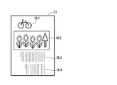
図3は、対象画像データによって表される対象画像の一例を示す図である。図3の対象画像OIは、線画などのコンピュータグラフィックスOb1(以下、単にグラフィックとも呼ぶ)、写真Ob2、文字Ob3、Ob4を含んでいる。対象画像OIを表す対象画像データは、複数個のオブジェクトOb1〜Ob4を規定する複数個の描画命令を含んでいる。 FIG. 3 is a diagram illustrating an example of a target image represented by target image data. The target image OI in FIG. 3 includes computer graphics Ob1 (hereinafter, also simply referred to as graphics) such as a line drawing, a photograph Ob2, and characters Ob3 and Ob4. The target image data representing the target image OI includes a plurality of drawing commands that define a plurality of objects Ob1 to Ob4.
グラフィックOb1、写真Ob2、文字Ob3、Ob4の描画命令は、これらのオブジェクトを描画するために必要な情報を含んでいる。例えば、グラフィックOb1の描画命令は、例えば、線や図形を示すベクトル、線や図形の種類、色、サイズなどの属性を規定する情報、配置位置を示す座標情報を含む。写真Ob2の描画命令は、例えば、JPEG形式の画像データなどのラスターデータ、サイズや使用される色空間などの写真の属性を規定する情報、配置位置を示す座標情報を含む。文字Ob3、Ob4の描画命令は、文字コード、フォントの種類、色、サイズなどの文字の属性を規定する情報、配置位置を示す座標情報を含む。 The drawing commands for the graphic Ob1, the photograph Ob2, the characters Ob3, and Ob4 include information necessary for drawing these objects. For example, the drawing command for the graphic Ob1 includes, for example, a vector indicating a line or a graphic, information defining attributes such as the type, color, and size of the line or graphic, and coordinate information indicating an arrangement position. The drawing command for the photograph Ob2 includes, for example, raster data such as image data in JPEG format, information defining the attributes of the photograph such as size and color space used, and coordinate information indicating the arrangement position. The drawing commands for the characters Ob3 and Ob4 include information defining character attributes such as a character code, font type, color, and size, and coordinate information indicating an arrangement position.
S15では、CPU210は、ユーザによって予め設定された画質に関する印刷モードが、鮮やかモードであるか、通常画質モードであるかを判断する。画質に関する印刷モードが鮮やかモードである場合には(S15:YES)、S20にて、CPU210は、鮮やかモード用のカラープロファイルを選択して、S30に処理を進める。画質に関する印刷モードが通常画質モードである場合には(S15:NO)、S25にて、CPU210は、通常画質モード用のカラープロファイルを選択して、S35に処理を進める。カラープロファイルは、所定の色空間の色値と、インク色に対応した色成分を含む色空間の色値と、の対応関係を規定するデータであり、後述する色変換処理において用いられる。本実施例のカラープロファイルは、RGB色空間の色値(RGB値とも呼ぶ)と、CMYK色空間の色値(CMYK値とも呼ぶ)と、の対応関係を規定したルックアップテーブルである。RGB値に含まれる各成分値、および、CMYK値に含まれる各成分値は、本実施例では、256階調の階調値である。鮮やかモード用のカラープロファイルを用いる場合には、通常画質モード用のカラープロファイルを用いる場合と比較して、印刷される画像において、有彩色がより鮮やかに表現される。鮮やかモード用のカラープロファイルを用いる場合には、通常画質モード用のカラープロファイルを用いる場合と比較して、トナーの消費量が大きくなる。
In S15, the
S30では、CPU210は、トナー消費量に関するモードが、通常トナーモードであるか、トナーセーブモードであるかを判断する。トナー消費量に関するモードが、トナーセーブモードである場合には(S30:YES)、CPU210は、S50に処理を進める。トナー消費量に関するモードが、通常トナーモードである場合には(S30:NO)、CPU210は、S35に処理を進める。
In S30, the
S35〜S45では、トナー消費量の抑制を行わない印刷データの生成処理が実行される。S35では、CPU210は、各オブジェクトの倍率を100%に決定する。ここで、オブジェクトの倍率は、後述するラスタライズ処理で、オブジェクトを縮小するための倍率であって、縮小前のオブジェクトのサイズに対する縮小後のオブジェクトのサイズの比率である。通常画質モードである場合、および、鮮やかモードであり、かつ、通常トナーモードである場合には、各オブジェクトの倍率が100%に決定されるので、後述するラスタライズ処理で、各オブジェクトは、対象画像データによって規定されたサイズから縮小されない。
In S35 to S45, print data generation processing that does not suppress toner consumption is executed. In S35, the
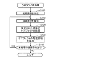
S40では、CPU210は、ラスタライズ処理を実行する。ラスタライズ処理は、対象画像データを用いて、ビットマップデータを生成する処理である。本実施例のビットマップデータは、例えば、RGB値で画素ごとの色を示すRGB画像データである。
In S40, the
図4は、ラスタライズ処理のフローチャートである。S100では、CPU210は、初期画像を表す初期画像データをバッファ領域222に準備する。初期画像は、生成すべき画像と同じサイズのRGB画像あって、各画素のRGB値が初期値(例えば、白を表す値)を有する画像である。S110では、CPU210は、画像対象画像データに含まれる1個以上の描画命令から、1個の描画命令を取得する。S120では、CPU210は、直前で決定された倍率で、描画命令によって規定されたサイズから縮小されたオブジェクトを初期画像内に描画する。図3のS40のラスタライズ処理では、図3のS25で決定された倍率が100%であるので、オブジェクトは、縮小されずに、描画命令によって(すなわち、対象画像データによって)規定されたサイズのままで、初期画像内に描画される。S130の処理は、S30のラスタライズ処理では、省略されるので、後述する。
FIG. 4 is a flowchart of rasterization processing. In S <b> 100, the
S140では、CPU210は、未処理の描画命令があるか否かを判断する。未処理の描画命令がある場合には(S140:YES)、CPU210は、S110に戻って、未処理の描画命令を取得する。全ての描画命令が処理された場合には(S140:YES)、CPU210は、ラスタライズ処理を終了する。
In S140, the
図2のS45では、CPU210は、色変換処理、および、ハーフトーン処理を実行して、印刷データを生成する。具体的には、色変換処理によって、RGB画像データは、S20またはS25にて選択されたカラープロファイルを用いて、CMYK値で画素ごとの色を表すCMYK画像データに変換される。そして、ハーフトーン処理によって、CMYK画像データは、CMYKの各成分について、画素ごとにドットの形成状態(本実施例では、ドットの有無)を示す印刷データが生成される。ハーフトーン処理には、ディザ法や誤差拡散法などの公知の手法が用いられる。S35で生成される印刷データによって表される印刷画像は、対象画像OIをそのまま表す画像、すなわち、対象画像データによって規定されたサイズのオブジェクトOb1〜Ob4を含む画像である。
In S45 of FIG. 2, the
S50では、すなわち、鮮やかモードが選択され、かつ、トナーセーブモードが選択された場合には、CPU210は、トナーの消費量の抑制を行う印刷データの生成処理(トナーセーブ時の印刷データ生成処理とも呼ぶ)を実行する(詳細は後述)。S50によって、上述したトナー消費量の抑制を行わない印刷データの生成処理(S35〜S45)とは異なる印刷データが生成される。
In S50, that is, when the vivid mode is selected and the toner save mode is selected, the
印刷データが生成されると、S55では、CPU210は、印刷データに、各種の印刷コマンドを付加して印刷ジョブを生成する。S60では、印刷ジョブを印刷装置300に送信する。印刷装置300は、受信した印刷ジョブに従って、用紙に画像を印刷する。
When the print data is generated, in S55, the
A−3.トナーセーブ時の印刷データ生成処理:
図5、図6は、トナーセーブ時の印刷データ生成処理のフローチャートである。トナーセーブ時の印刷データ生成処理は、オブジェクトごとに決定される倍率で、図3の対象画像OIに含まれる各オブジェクトを、対象画像データによって規定されるサイズから縮小することによって、縮小された複数個のオブジェクトを含む処理済画像を表す印刷データを生成する処理である。
A-3. Print data generation processing when saving toner:
5 and 6 are flowcharts of print data generation processing during toner save. The print data generation process at the time of toner save is performed by reducing each object included in the target image OI of FIG. 3 from the size defined by the target image data at a magnification determined for each object. This is a process for generating print data representing a processed image including an object.
S300では、CPU210は、各オブジェクトの倍率を100%に決定する。S305では、CPU210は、上述した図4のラスタライズ処理を実行する。なお、S305のラスタライズ処理でも、図4のS130の処理は実行されない。S300、S305の処理によって、通常画質モードや通常トナーモード時に生成されるRGB画像データ、すなわち、対象画像データによって規定されたサイズのオブジェクトOb1〜Ob4を含む画像を表すRGB画像データが生成される。
In S300, the
S310では、CPU210は、通常画質モード用のカラープロファイルを選択する。S315では、CPU210は、色変換処理、および、ハーフトーン処理を実行して、印刷データを生成する。すなわち、S305で生成されたRGB画像データに対して、通常画質モード用のカラープロファイルを用いた色変換処理が実行されて、CMYK画像データが生成される。そして、CMYK画像データに対してハーフトーン処理が実行されて、印刷データが生成される。これによって、画質に関するモードが、通常画質モードである場合に生成される印刷データが生成される。
In S310, the
S320では、CPU210は、S315にて生成された印刷データを用いて、この印刷データを用いて画像を印刷した場合に、用紙上に形成されるドットの総数を示すドット数Dorgを算出する。ドット数Dorgは、CMYKの各トナーで形成されるドットの合計値である。ドット数Dorgは、対象画像データによって規定されたサイズのオブジェクトを含む画像を、通常画質モードで印刷する場合に、消費されるトナー量を示す指標値と言うことができる。
In S320, the
S325では、CPU210は、鮮やかモード用のカラープロファイルを選択する。S330では、CPU210は、色変換処理、および、ハーフトーン処理を実行して、印刷データを生成する。すなわち、S305で生成されたRGB画像データに対して、鮮やかモード用のカラープロファイルを用いた色変換処理が実行されて、CMYK画像データが生成される。そして、CMYK画像データに対してハーフトーン処理が実行されて、印刷データが生成される。これによって、画質に関するモードが鮮やかモードであり、かつ、トナー消費量に関するモードが、通常トナーモードである場合に生成される印刷データが生成される。
In S325, the
S335では、CPU210は、S330にて生成された印刷データを用いて、この印刷データを用いて画像を印刷した場合に、用紙上に形成されるドットの総数を示すドット数Dvvdを算出する。ドット数Dvvdは、CMYKの各トナーで形成されるドットの合計値である。ドット数Dvvdは、対象画像データによって規定されたサイズのオブジェクトを含む画像を、鮮やかモードで印刷する場合に、消費されるトナー量を示す指標値と言うことができる。
In S335, the
S340では、CPU210は、S335にて算出されたドット数Dvvdと、S320にて算出されたドット数Dorgと、の差分(Dvvd−Dorg)を算出する。ドット数Dvvdは、ドット数Dorgより大きな値となるので、差分(Dvvd−Dorg)は、正の値となる。差分(Dvvd−Dorg)は、対象画像データによって規定されたサイズからオブジェクトを縮小することなく、鮮やかモードで印刷する場合において、通常モードで印刷する場合と比較してドット数が増加する量を示す。
In S340, the
S345では、CPU210は、差分(Dvvd−Dorg)に基づいて、対象画像OIに含まれる各オブジェクトの倍率を決定する。具体的には、先ず、CPU210は、ドット数の増加量を示す差分(Dvvd−Dorg)を、ドット数の増加率TRに変換する(TR=((Dvvd−Dorg)/Dorg)。ドット数の増加率TRは、通常画質用のカラープロファイルと鮮やかモード用のカラープロファイルとの特性の違いや、対象画像データによって異なるが、本実施例では、数%〜10%程度の値となる。CPU210は、ドット数の増加率TRと、倍率と、の関係を規定したテーブルTBを参照して、対象画像OIに含まれる各オブジェクトの倍率を決定する。テーブルTBは、コンピュータプログラム232に予め組み込まれている。
In S345, the
図7は、テーブルTBに規定されたドット数の増加率TRと倍率との関係を示すグラフである。図7において、破線PCは、オブジェクトが写真である場合におけるドット削減率の目標THdと倍率との関係を示す。同様に、実線GR、一点破線TXは、オブジェクトがグラフィックである場合、および、オブジェクトが文字である場合について、ドット数の増加率TRと倍率との関係をそれぞれ示す。 FIG. 7 is a graph showing the relationship between the increase rate TR of the number of dots defined in the table TB and the magnification. In FIG. 7, a broken line PC indicates the relationship between the target THd of the dot reduction rate and the magnification when the object is a photograph. Similarly, the solid line GR and the one-dot broken line TX indicate the relationship between the dot number increase rate TR and the magnification when the object is a graphic and when the object is a character, respectively.
図7に示すように、いずれのオブジェクトの種類についても、ドット数の増加率TRが大きいほど、倍率は小さな値に決定される。すなわち、ドット数の増加率TRが大きいほど、オブジェクトを縮小する程度は大きくされる。ドット数の増加率TRが大きいほど、オブジェクトを縮小してドット数を削減する必要性が大きいからである。ただし、倍率について下限値(本実施例では、95%)が設定されているので、倍率は、下限値より小さな値に設定されることはない。下限値は、印刷されたオブジェクトを観察者が一見した場合に、オブジェクトが縮小されていることに気づかない程度の倍率に決定されている。 As shown in FIG. 7, for any type of object, the larger the dot number increase rate TR, the smaller the magnification is determined. That is, the greater the dot rate increase rate TR, the greater the extent to which the object is reduced. This is because the larger the dot rate increase rate TR, the greater the need to reduce the number of dots by reducing the object. However, since a lower limit value (95% in this embodiment) is set for the magnification, the magnification is not set to a value smaller than the lower limit value. The lower limit value is set to a magnification that does not notice that the object is reduced when the observer looks at the printed object.
図7から解るように、倍率は、本実施例では、オブジェクトの種類によって異なる値に決定される。具体的には、写真の倍率は、グラフィックの倍率と比較して、小さな値に決定される。ただし、両方の倍率が下限値に決定される場合は、両方の倍率は同じになる。同様に、写真の倍率は、文字の倍率と比較して、小さな値に決定される。グラフィックの倍率は、文字の倍率と比較して、小さな値に決定される。以上の説明から解るように、例えば、図3の対象画像OIを表す対象画像データが処理の対象である場合には、小さな順に、写真Ob2の倍率R2、グラフィックOb1の倍率R1、文字Ob3、Ob4の倍率R3に決定される(R2<R1<R3)。 As can be seen from FIG. 7, in this embodiment, the magnification is determined to be a different value depending on the type of object. Specifically, the magnification of the photograph is determined to be a small value compared with the magnification of the graphic. However, when both magnifications are determined as the lower limit values, both magnifications are the same. Similarly, the magnification of the photograph is determined to be a small value as compared with the magnification of the character. The graphic magnification is determined to be smaller than the character magnification. As can be understood from the above description, for example, when the target image data representing the target image OI of FIG. Magnification R3 (R2 <R1 <R3).
このようにオブジェクトごとに倍率を決定することによって、対象画像の全体を縮小する場合、すなわち、全てのオブジェクトを同じ倍率で縮小する場合と比較して、効率的にドット数(トナー消費量)を削減することができる。より具体的に説明する。オブジェクトの全体が配置される領域(例えば、オブジェクトの外接矩形の領域)の面積S1に対するオブジェクトを構成する画素が配置される領域(換言すれば、印刷時にドットが形成されるべき領域)の面積S2の比率(S2/S1)をオブジェクト密度と呼ぶ。一般的に、オブジェクト密度は、写真、グラフィック、文字の順で高い。オブジェクトが縮小された場合に、ドット数が減少する割合DRは、縮小時の倍率によって決まる。このために、縮小前のドットの総数に割合DRを乗じた値で表されるドットの減少数は、縮小時の倍率が同じであれば、縮小前のドットの総数が多いほど、すなわち、オブジェクトを構成する画素が配置される領域の面積S2が大きいほど多くなる。したがって、単位面積辺りのドットの減少数は、縮小時の倍率が同じであれば、オブジェクト密度が高いほど多くなる。以上の説明から解るように、オブジェクト密度が高いオブジェクト(例えば、写真)の倍率をオブジェクト密度が低いオブジェクト密度が低いオブジェクト(例えば、文字)の倍率より低くする方が、効率的にドット数を削減することができる。 By determining the magnification for each object in this way, the number of dots (toner consumption) can be efficiently reduced as compared with the case where the entire target image is reduced, that is, when all objects are reduced at the same magnification. Can be reduced. This will be described more specifically. Area S2 of a region (in other words, a region in which dots are to be formed at the time of printing) where pixels constituting the object are arranged relative to area S1 of a region where the entire object is arranged (for example, a circumscribed rectangular region of the object) The ratio (S2 / S1) is called object density. In general, the object density is high in the order of photos, graphics, and characters. When the object is reduced, the rate DR at which the number of dots decreases is determined by the magnification at the time of reduction. For this reason, the dot reduction number represented by a value obtained by multiplying the total number of dots before reduction by the ratio DR is larger as the total number of dots before reduction is larger if the magnification at the time of reduction is the same. The larger the area S2 of the region where the pixels constituting the pixel are arranged, the larger the area. Therefore, the number of dots per unit area decreases as the object density increases if the magnification at the time of reduction is the same. As can be seen from the above description, it is more efficient to reduce the number of dots by reducing the magnification of an object with a high object density (for example, a photograph) to be lower than the magnification of an object with a low object density (for example, a character). can do.
図5のS350では、CPU210は、図4のラスタライズ処理を実行する。S350のラスタライズ処理では、図4のS130の処理が実行される。図4のS130では、CPU210は、S120で描画されたオブジェクトの配置面積Sを算出する。配置面積Sは、例えば、オブジェクトの外接矩形の面積である。S350のラスタライズ処理によって、例えば、S345で決定されたオブジェクトの種類ごとに異なる倍率で縮小されたオブジェクトを含む画像を表すRGB画像データが生成される。
In S350 of FIG. 5, the
S355では、CPU210は、直前に生成されたRGB画像データを用いて、上述した色変換処理およびハーフトーン処理を実行する。色変換処理に用いられるカラープロファイルは、鮮やかモード用のカラープロファイルである。この結果、オブジェクトの種類ごとに異なる倍率で縮小されたオブジェクトを含む画像を表す印刷データが生成される。
In S355, the
S360では、CPU210は、S355にて生成された印刷データを用いて、この印刷データを用いて画像を印刷した場合に、用紙上に形成されるドットの総数を示すドット数Dnewを算出する。ドット数Dnewは、対象画像データによって規定されたサイズからオブジェクトの種類ごとに異なる倍率で縮小されたオブジェクトを含む画像を、鮮やかモードで印刷する場合に、消費されるトナー量を示す指標値と言うことができる。
In S360, the
図6のS365では、CPU210は、S360にて算出されたドット数Dnewと、S320にて算出されたドット数Dorgと、の差分(Dnew−Dorg)を算出する。差分(Dnew−Dorg)は、対象画像データによって規定されたサイズからオブジェクトを縮小して、鮮やかモードで印刷する場合において、通常モードで印刷する場合と比較してドット数が増加する量を示す。
In S365 of FIG. 6, the
S368では、CPU210は、ドット数の増加量の目標値THtを決定する。目標値THtは、S340で算出された差分(Dvvd−Dorg)に所定の係数Kを乗じた値に決定される(THt=K×(Dvvd−Dorg))。係数Kは、例えば、0〜0.5の範囲内の値、本実施例では、0.3に予め設定されている。換言すれば、対象画像データによって規定されたサイズからオブジェクトを縮小することによって、ドット数の増加量を、オブジェクトを縮小しない場合のドット数の増加量の30%以下に抑制するように、目標値Thtが決定される。
In S368, the
S370では、CPU210は、差分(Dnew−Dorg)が目標値THt以下であるか否かを判断する。換言すれば、オブジェクトを縮小することによって、ドット数の増加量が目標値THt以下に抑制されたか否かが確認される。差分(Dnew−Dorg)が目標値THt以下である場合には(S370:YES)、CPU210は、トナーセーブ時の印刷データ生成処理を終了する。
In S370, the
差分(Dnew−Dorg)が目標値THtより大きい場合には(S370:NO)、CPU210は、よりドット数の増加量(すなわち、消費されるトナーの増加量)を抑制すべく、オブジェクトの倍率を変更して、再度、印刷データを生成するためのリトライ処理(S375〜S425)を実行する。
When the difference (Dnew-Dorg) is larger than the target value THt (S370: NO), the
S375では、CPU210は、S375〜S425のリトライ処理が実行された回数を示すリトライ回数Mが、本実施例の上限回数である3以上である否かを判断する。なお、Mの初期値は、0である。
In S375, the
リトライ回数Mが3以上である場合には(S370:YES)、CPU210は、トナーセーブ時の印刷データ生成処理を終了する。リトライ回数Mが3未満である場合には(S370:NO)、S380にて、CPU210は、リトライ回数Mに1を加算する。
If the number of retries M is 3 or more (S370: YES), the
S385では、CPU210は、対象画像データに含まれる複数個の描画命令の処理順を決定する。具体的には、直前の描画時に、描画されたオブジェクトの配置面積が大きい順に、当該オブジェクトの描画命令の処理順が決定される。直前の描画時は、1回目のリトライ処理の場合には、上述した図5のS350のラスタライズ処理において、オブジェクトが描画される時(図4のS120)であり、図4のS130で算出されたオブジェクトの配置面積に基づいて、描画命令の処理順が決定される。直前の描画時は、2回目および3回目のリトライ処理の場合には、後述する図6のS415にて、オブジェクトが描画される時であり、後述する図6のS420で算出されたオブジェクトの配置面積に基づいて、描画命令の処理順が決定される。ここで、直前の描画時とされるのは、描画命令が処理される度に、オブジェクトを縮小するための倍率が異なり得るためである。例えば、図3の対象画像OIの場合には、オブジェクトの配置面積は、大きい順に、写真Ob2、文字Ob3、文字Ob4、グラフィックOb1の順であるので、写真Ob2の描画命令、文字Ob3の描画命令、文字Ob4の描画命令、グラフィックOb1の描画命令の順に、処理順が決定される。
In S385, the
オブジェクトが大きいほど、該オブジェクトを縮小した場合に、ドット数を低減できる程度が大きくなる。このために、よりドット数の増加量を抑制すべく、後述するS405にて、オブジェクトの倍率をより小さな値に変更する際に、配置面積が大きなオブジェクトの倍率を優先的に変更することが好ましい。このために、S385では、オブジェクトの配置面積が大きい順に、描画命令の処理順が決定される。 The larger the object, the greater the extent to which the number of dots can be reduced when the object is reduced. For this reason, it is preferable to preferentially change the magnification of an object having a large arrangement area when changing the magnification of the object to a smaller value in S405 to be described later in order to further suppress the increase in the number of dots. . For this reason, in S385, the processing order of the drawing commands is determined in descending order of the object layout area.
S390では、CPU210は、リトライ回数Mに応じて、倍率変更数Nthを決定する。倍率変更数は、対象画像に含まれる複数個のオブジェクトのうち、リトライ処理において、倍率をより小さな値に変更するオブジェクトの個数、すなわち、縮小する程度をより大きく変更するオブジェクトの個数である。具体的には、1回目のリトライ処理では、倍率変更数Nthは、対象画像に含まれるオブジェクトの総数Nsの25%以下の最大の整数に決定される。同様に、2回目、および、3回目のリトライ処理では、倍率変更数Nthは、対象画像に含まれるオブジェクトの総数Nsの50%以下、および、75%以下の最大の整数にそれぞれ決定される。例えば、図3の対象画像OIは、4個のオブジェクトOb1〜Ob4を含んでいるので(Ns=4)、図3の対象画像OIを表す画像データが処理の対象である場合には、1回目、2回目、3回目のリトライ処理における倍率変更数Nthは、1、2、3にそれぞれ決定される。
In S390, the
S392〜S425では、倍率を変更しながら対象画像データをラスタライズするリトライ時のラスタライズ処理が実行される。先ず、S392では、CPU210は、図4のS100と同様に、初期画像を表す初期画像データをバッファ領域222に準備する。S395では、CPU210は、S385にて決定された処理順に、処理対象の描画命令を取得する。
In S392 to S425, a rasterizing process at the time of retry for rasterizing the target image data while changing the magnification is executed. First, in S392, the
S400では、CPU210は、処理対象の描画命令の処理順n(nは、1≦n≦Nsの整数)が、倍率変更数Nth以下であるか否かを判断する。処理対象の描画命令の処理順nが、倍率変更数Nth以下である場合には(S400:YES)、S405にて、CPU210は、処理対象の描画命令によって描画されるオブジェクトの現在の倍率Rから2%を減じた値(R−2)が、倍率の下限値(本実施例では95%)以上であるか否かを判断する。(R−2)が、倍率の下限値以上である場合には(S405:YES)、S410にて、CPU210は、処理対象の描画命令によって描画されるオブジェクトの倍率を2%だけ小さな値に変更する。
In S400, the
(R−2)が、倍率の下限値より小さい場合には(S405:NO)、倍率が下限値より小さくならないようにするため、該オブジェクトの倍率を変更することなく、S415に処理を進める。処理対象の描画命令の処理順nが、倍率変更数Nthより大きい場合には(S400:NO)、当該描画命令によって描画されるオブジェクトの倍率は、変更対象とはしないので、CPU210は、S405、S410をスキップして、S415に処理を進める。
If (R-2) is smaller than the lower limit value of the magnification (S405: NO), the process proceeds to S415 without changing the magnification of the object in order to prevent the magnification from becoming smaller than the lower limit value. When the processing order n of the rendering command to be processed is larger than the magnification change number Nth (S400: NO), since the magnification of the object drawn by the rendering command is not a change target, the
S415では、CPU210は、直前で決定された倍率で、描画命令によって規定されたサイズから縮小されたオブジェクトを初期画像内に描画する。すなわち、直前のS405にて、倍率が変更されている場合には、変更後の倍率で縮小されたオブジェクトが初期画像内に描画される。倍率が変更されていない場合には、前回のラスタライズ処理と同じ倍率で縮小されたオブジェクトが初期画像内に描画される。
In S415, the
S420では、図4のS130と同様に、CPU210は、S415で描画されたオブジェクトの配置面積Sを算出する。ここで算出された配置面積Sは、次回のリトライ処理が行われる場合に、次回のリトライ処理のS385で、描画命令の処理順を決定するために用いられる。
In S420, as in S130 of FIG. 4, the
S425では、CPU210は、未処理の描画命令があるか否かを判断する。未処理の描画命令がある場合には(S425:YES)、CPU210は、S395に戻って、未処理の描画命令を取得する。全ての描画命令が処理された場合には(S425:YES)、CPU210は、S355に戻る。この時点で、リトライ時のラスタライズ処理が完了して、一部のオブジェクトの倍率が変更された後の画像を表すRGB画像データが生成される。
In S425, the
S355にて、新たなRGB画像データに対して、色変換処理とハーフトーン処理が実行された新たな印刷データが生成される。そして、S360〜S370にて、新たな印刷データについて、ドット数の増加量(すなわち、差分(Dnew−Dorg))が目標値THt以下に抑制されたか否かが確認される。そして、ドット数の増加量が目標値THt以下に抑制された場合(S370:YES)、あるいは、リトライ回数Mが上限回数(例えば、3回)に達した場合に(S375:YES)、CPU210は、トナーセーブ時の印刷データ生成処理を終了する。
In S355, new print data in which color conversion processing and halftone processing are executed is generated for the new RGB image data. In S360 to S370, it is confirmed whether or not the amount of increase in the number of dots (that is, the difference (Dnew-Dorg)) is suppressed to the target value THt or less for the new print data. When the amount of increase in the number of dots is suppressed below the target value THt (S370: YES), or when the number of retries M reaches the upper limit number (for example, 3 times) (S375: YES), the
以上説明した本実施例によれば、CPU210は、第1のオブジェクト(例えば、図3の文字Ob3)と、第2のオブジェクト(例えば、図3の写真Ob2)と、を含む複数個のオブジェクトを含む1個の対象画像OI(図3)を表す対象画像データを取得する(図2のS10)。そして、印刷モードに応じて、カラープロファイルが選択されることによって(図3のS15〜S25)、印刷を実行する際の画質が決定される。
According to the present embodiment described above, the
そして、CPU210は、第1の画質(例えば、通常画質モードでの画質)で印刷を行う場合に、対象画像データに基づいて、複数個のオブジェクトが対象画像データによって規定されるサイズにて表現される画像(すなわち、対象画像OIをそのまま表す印刷画像)を印刷装置300に印刷させる(図2のS35〜S45、S55、S60)。一方、CPU210は、第2の画質(例えば、鮮やかモードでの画質)で印刷を行う場合に、対象画像データによって規定されるサイズからオブジェクトのサイズが縮小された画像(処理済画像とも呼ぶ)を表す印刷データ(すなわち、図5、図6のトナーセーブ時の印刷データ生成処理によって生成される印刷データ)に基づいて、当該画像を印刷装置300に印刷させることができる。
Then, when printing with the first image quality (for example, the image quality in the normal image quality mode), the
図5のトナーセーブ時の印刷データ生成処理では、CPU210は、複数個のオブジェクトのそれぞれについて倍率を決定する(例えば、図5のS345)。例えば、第1のオブジェクト(例えば、図3の文字Ob3)の倍率は、第1の倍率に決定され、第2のオブジェクト(例えば、図3の写真Ob2)の倍率は、第1の倍率とは異なる第2の倍率に決定される。
In the print data generation process at the time of toner save in FIG. 5, the
そして、例えば、図5のS350のラスタライズ処理およびS355の色変換およびハーフトーン処理によって、対象画像データを用いて、印刷データを生成する。印刷データによって表される画像において、第1のオブジェクトは、対象画像データによって規定されるサイズから第1の倍率で縮小され、第2のオブジェクトは、対象画像データによって規定されるサイズから第2の倍率で縮小される。 Then, for example, print data is generated using the target image data by the rasterization process in S350 of FIG. 5 and the color conversion and halftone process in S355. In the image represented by the print data, the first object is reduced from the size specified by the target image data at the first magnification, and the second object is reduced from the size specified by the target image data to the second. Reduced by magnification.
この結果、各オブジェクトOb1〜Ob4は、オブジェクトごとに適切なサイズに縮小される。この結果、印刷される画像の画質の低下を抑制しつつ、トナーの消費量を抑制することができる。すなわち、トナーセーブ時の印刷データ生成処理では、鮮やかモード用のカラープロファイルを用いて、色変換処理(図5のS355)が行われるので、通常画質モードより鮮やかな高い画質を実現できる。一方、各オブジェクトは、対象画像データによって規定されるサイズからオブジェクトごとに適切に縮小されているので、過度に画像が縮小されることなく、効率良くトナーの消費量を抑制することができる。 As a result, each of the objects Ob1 to Ob4 is reduced to an appropriate size for each object. As a result, it is possible to suppress toner consumption while suppressing deterioration in image quality of the printed image. That is, in the print data generation process at the time of toner save, the color conversion process (S355 in FIG. 5) is performed using the color profile for the vivid mode, so that it is possible to realize a brighter and higher image quality than in the normal image quality mode. On the other hand, since each object is appropriately reduced for each object from the size defined by the target image data, it is possible to efficiently suppress toner consumption without excessively reducing the image.
例えば、鮮やかモードで印刷を行う際に、過度にトナーの消費量が多くなると、通常画質モードで印刷を行う場合と比較して、印刷可能な枚数が大幅に減ってしまう。ユーザは、鮮やかモードで印刷を行う場合であっても、トナーセーブモードを指示することによって、このような不具合を抑制できる。 For example, when the toner consumption is excessively increased when printing in the vivid mode, the number of printable sheets is greatly reduced as compared with the case of printing in the normal image quality mode. Even when printing is performed in the vivid mode, the user can suppress such a problem by instructing the toner save mode.
また、上述した印刷する際の画質は、ユーザの指示に基づいて決定される。具体的には、印刷する際の画質は、上述したように、ユーザによって指定された印刷モードに基づいて決定される(図2のS15〜S25)。この結果、ユーザの指示に基づいて決定される画質に応じて、印刷される画像の画質の低下を抑制しつつ、トナーの消費量を抑制することができる。 Further, the image quality at the time of printing described above is determined based on a user instruction. Specifically, the image quality at the time of printing is determined based on the printing mode designated by the user as described above (S15 to S25 in FIG. 2). As a result, according to the image quality determined based on the user's instruction, it is possible to suppress the toner consumption while suppressing the deterioration of the image quality of the printed image.
さらに、上記実施例では、印刷モードが鮮やかモードである場合には、ユーザの指示に基づいてトナーの消費量を低減するか否かが選択される。具体的には、上述したように、ユーザによってトナーセーブモードに設定されている場合には(図2のS30:YES)、トナーの消費量を低減することが選択されて、トナーセーブ時の印刷データ生成処理が実行される(S50)。換言すれば、CPU210は、鮮やかモードで印刷を行う場合であって、かつ、ユーザの指示に基づいてトナーの消費量を低減することが選択された場合に、オブジェクトごとに決定される倍率でオブジェクトが縮小された画像を印刷装置300に印刷させる。したがって、ユーザがトナーの消費量の低減を指示した場合に、印刷される画像の画質の低下を抑制しつつ、トナーの消費量を抑制することができる。
Further, in the above-described embodiment, when the print mode is the vivid mode, whether to reduce the toner consumption is selected based on a user instruction. Specifically, as described above, when the toner save mode is set by the user (S30 in FIG. 2: YES), it is selected to reduce the toner consumption, and printing at the time of toner save is performed. Data generation processing is executed (S50). In other words, when the
さらに、上記実施例では、CPU210は、対象画像データによって規定されるサイズのオブジェクトを含む画像(すなわち、対象画像をそのまま表す印刷画像)を通常画質モードで印刷する場合に消費される第1の色材量を示すドット数Dorgを算出する(図5のS320)。さらに、CPU210は、対象画像データによって規定されるサイズのオブジェクトを含む印刷画像を鮮やかモードで印刷する場合に消費される第2の色材量を示すドット数Dvvdを算出する(図5のS335)。そして、CPU210は、差分(Dvvd−Dorg)に基づいて、各オブジェクトの倍率を決定する(図5のS340、S345)。この結果、オブジェクトごとに適切な倍率を決定することができる。例えば、差分(Dvvd−Dorg)が大きいほど、オブジェクトの倍率を小さくして、オブジェクトを縮小する程度が大きくされる(図7)。この結果、鮮やかモードで印刷する場合のトナー消費量が、通常画質モードで印刷する場合と比較して、過度に大きくならないように、適切な倍率を決定することができる。
Further, in the above-described embodiment, the
さらに、CPU210は、S350、S355にて生成された印刷データによって表される画像、すなわち、オブジェクトごとに決定される倍率でオブジェクトが縮小された画像を印刷する場合に消費される第3の色材量を示すドット数Dnewを算出する(図5のS360)。そして、差分(Dnew−Dorg)と目標値THtとを比較する(図6のS370)。そして、差分(Dnew−Dorg)がTHtより大きい場合に(S370:YES)、CPU210は、リトライ処理を実行する(図6のS375〜S425)。このように、トナー消費量の増加量を十分に抑制できたか否かを確認する処理を行って、十分に抑制できていな場合には、リトライ処理を行うので、トナーの消費量を十分に抑制できない可能性を低減することができる。なお、差分(Dnew−Dorg)と目標値THtとを比較することは、Dnewと、特定の閾値(目標値Tht+Dorg)と、を比較することと等しい。
Further, the
さらに、本実施例のリトライ処理では、CPU210は、Ns個のオブジェクトのうち、配置面積が大きい順にNth番目までのオブジェクトの倍率を変更し、Nth以降のオブジェクトの倍率を変更しない(図6のS390、S400〜S410)。換言すれば、CPU210は、複数個のオブジェクトのうち、第1の面積を有するオブジェクトの倍率を変更し、第1の面積より小さな第2の面積を有するオブジェクトの倍率を変更しない。これによって、印刷時におけるトナーの消費量が比較的大きなオブジェクトの倍率を、トナーの消費量が比較的小さなオブジェクトの倍率より優先的に変更する。この結果、リトライ処理後の印刷データによって表される画像を印刷する際のトナーの消費量を効率的に低減することができる。したがって、トナーの消費量を低減するために、オブジェクトが過度に小さくなることを抑制することができる。
Further, in the retry process of the present embodiment, the
さらに、リトライ処理は、差分(Dnew−Dorg)がTHt以下になるまで、複数回実行される(図6のS370)。したがって、トナーの消費量が十分に低減することができる。また、リトライ処理において、CPU210は、複数個のオブジェクトのうち、倍率が特定の下限値(例えば、95%)に達したオブジェクトの倍率は変更しない(図6のS405)。この結果、印刷される画像が過度に小さくならない範囲で、トナーの消費量を低減することができる。
Further, the retry process is executed a plurality of times until the difference (Dnew-Dorg) becomes equal to or less than THt (S370 in FIG. 6). Therefore, the toner consumption can be sufficiently reduced. In the retry process, the
図7に示すように、図5のS345では、CPU210は、文字とは異なるオブジェクト(例えば、グラフィックや写真)の倍率を、文字の倍率より小さな値に決定する。換言すれば、文字とは異なるオブジェクトを縮小する程度を、文字を縮小する程度より大きく決定する。上述したように、一般的に、文字領域のオブジェクト密度は、文字とは異なるオブジェクトのオブジェクト密度より小さい。このために、文字とは異なるオブジェクトの倍率を、文字の倍率より小さくすることによって、効率的にトナーの消費量を低減することができる。
As shown in FIG. 7, in S345 of FIG. 5, the
B.変形例:
(1)上記実施例のリトライ処理では、CPU210は、複数個のオブジェクトのうち、配置面積Sが比較的大きなオブジェクトの倍率を変更し、配置面積Sが比較的小さなオブジェクトの倍率を変更しないことによって、印刷時におけるトナーの消費量が比較的大きなオブジェクトの倍率を、トナーの消費量が比較的小さなオブジェクトの倍率より優先的に変更している(図6のS390、S400〜S410)。これに限らず、例えば、CPU210は、複数個のオブジェクトのうち、オブジェクト密度が比較的大きなオブジェクトの倍率を変更し、オブジェクト密度が比較的小さなオブジェクトの倍率を変更しないことによって、印刷時におけるトナーの消費量が比較的大きなオブジェクトの倍率を、トナーの消費量が比較的小さなオブジェクトの倍率より優先的に変更しても良い。また、色が濃いほどトナーの消費量が大きくなる傾向があるので、CPU210は、複数個のオブジェクトのうち、比較的濃度が高い色を有するオブジェクトの倍率を変更し、比較的濃度が低い色を有するオブジェクトの倍率を変更しないことによって、印刷時におけるトナーの消費量が比較的大きなオブジェクトの倍率を、トナーの消費量が比較的小さなオブジェクトの倍率より優先的に変更しても良い。具体的には、CPU210は、オブジェクトの代表色(例えば、平均色)をCMYK値で表した場合に、該CMYK値の各成分値が大きいほど濃度が高い色であると判断しても良い。あるいは、CPU210は、オブジェクトのヒストグラムを生成し、オブジェクトを構成する画素のうち、濃度が閾値以上の画素の個数を算出しても良い。そして、濃度が閾値以上の画素の個数が多いほど、濃度が高い色を有するオブジェクトであると判断しても良い。
B. Variations:
(1) In the retry process of the above embodiment, the
(2)上記実施例では、印刷装置300は色材としてトナーを用いるレーザープリンタであるが、印刷装置300は、色材としてのインクを吐出してドットを形成することによって印刷を行うインクジェットプリンタであっても良い。この場合には、図5、図6の処理によって、印刷される画像の画質の低下を抑制しつつ、インクの消費量を抑制することができる。
(2) In the above embodiment, the
(3)上記実施例では、鮮やかモードに設定され、かつ、トナーセーブモードに設定された場合に、図5、図6の処理が実行され、鮮やかモードに設定された場合であっても、トナーセーブモードに設定されていない場合には、図5、図6の処理が実行されない。これに代えて、鮮やかモードに設定された場合には、常に、図5、図6の処理が実行されても良い。 (3) In the above embodiment, when the bright mode is set and the toner save mode is set, the processing of FIGS. 5 and 6 is executed, and the toner is set even when the bright mode is set. When the save mode is not set, the processes of FIGS. 5 and 6 are not executed. Instead of this, when the vivid mode is set, the processes of FIGS. 5 and 6 may always be executed.
(4)上記実施例では、オブジェクトの種類によってオブジェクト密度が異なることに着目して、オブジェクトの種類に応じてオブジェクトの倍率が決定されている。これに限らず、様々な手法でオブジェクトごとに異なる倍率が決定され得る。具体的には、実施例のように、複数個のオブジェクトのうち、印刷時におけるトナーの消費量が比較的大きなオブジェクトの倍率を、トナーの消費量が比較的小さなオブジェクトの倍率より小さく決定される手法が採用されることが好ましい。こうすれば、例えば、画像全体を特定の倍率で縮小する場合と比較して、効率的に、トナーの消費量を低減することができる。例えば、配置面積Sが比較的大きなオブジェクトの倍率を、配置面積Sが比較的小さなオブジェクトの倍率より小さな値としても良い。あるいは、比較的濃度が高い色を有するオブジェクトの倍率を、比較的濃度が低い色を有するオブジェクトの倍率より小さな値としても良い。 (4) In the above embodiment, paying attention to the fact that the object density varies depending on the object type, the magnification of the object is determined according to the object type. Not limited to this, different magnifications can be determined for each object by various methods. Specifically, as in the embodiment, the magnification of an object that consumes a relatively large amount of toner during printing among a plurality of objects is determined to be smaller than the magnification of an object that consumes a relatively small amount of toner. It is preferable that a technique is adopted. In this way, for example, the amount of toner consumed can be reduced more efficiently than when the entire image is reduced at a specific magnification. For example, the magnification of an object having a relatively large arrangement area S may be set to a value smaller than the magnification of an object having a relatively small arrangement area S. Alternatively, the magnification of an object having a relatively high density color may be set to a value smaller than the magnification of an object having a relatively low density color.
(5)上記実施例において、図6のS368にて、ドット数の増加量の目標値THtは、差分(Dvvd−Dorg)に所定の係数Kを乗じて決定されている。この係数Kは、上記実施例では、固定値であるが、動的に決定されても良い。例えば、係数Kは、対象画像に含まれるオブジェクトの種類に応じて、決定されても良い。具体的には、対象画像に含まれる複数個のオブジェクトに占める写真の割合が高くなるほど、係数Kの値を小さくすることによって、より厳しい目標値THtを設定しても良い。写真の割合が高い画像は、トナーの消費量が多くなりがちであるので、トナーの消費量を削減する意義が大きいからである。そして、係数Kの値が小さく設定されるほど、換言すれば、厳しい目標値THtが設定されるほど、写真の倍率の下限値を小さくしても良い。この場合に、写真の倍率の下限値は、他のオブジェクト(例えば、文字)の倍率の下限値より小さくされても良い。写真の倍率の下限値を小さくすることは、トナーの消費量を削減する効果が高いからである。また、写真は、縮小によって読みづらくなる不都合を生じ得る文字と比較して、縮小目立ち難いため、写真の倍率を小さくすることは、許容されやすいからである。 (5) In the above embodiment, in S368 of FIG. 6, the target value THt of the amount of increase in the number of dots is determined by multiplying the difference (Dvvd-Dorg) by a predetermined coefficient K. The coefficient K is a fixed value in the above embodiment, but may be determined dynamically. For example, the coefficient K may be determined according to the type of object included in the target image. Specifically, the stricter target value THt may be set by decreasing the value of the coefficient K as the ratio of photographs to a plurality of objects included in the target image increases. This is because an image with a high proportion of photographs tends to consume a large amount of toner, so that it is significant to reduce the amount of toner consumed. Then, the lower the value of the coefficient K is set, in other words, the lower the lower limit value of the magnification of the photograph is set, the more strict target value THt is set. In this case, the lower limit value of the magnification of the photograph may be made smaller than the lower limit value of the magnification of another object (for example, a character). This is because reducing the lower limit of the photograph magnification has a high effect of reducing the toner consumption. Further, since a photograph is less conspicuous than a character that may cause inconvenience that becomes difficult to read due to the reduction, it is easy to allow a reduction in the magnification of the photograph.
(6)上記実施例において、リトライ処理は省略されても良い。具体的には、図5のS355の後に、トナーセーブ時の印刷データ生成処理は終了され、S360〜S425の処理は省略されても良い。 (6) In the above embodiment, the retry process may be omitted. Specifically, after S355 of FIG. 5, the print data generation process at the time of toner saving may be terminated, and the processes of S360 to S425 may be omitted.
(7)図2の印刷処理を実現する画像処理装置は、計算機200に限らず、種々の装置であってよい。例えば、プリンタ内においてプリンタを制御する制御装置が、プリンタ内のプリントエンジンに印刷を実行させるために、図2の印刷処理を実行しても良い。あるいは、プリンタに、インターネットを介して接続されたサーバや、プリンタに無線ネットワークを介して接続されたスマートフォンなどの携帯端末等が、図2の印刷処理を実行しても良い。また、ネットワークを介して互いに通信可能な複数個のコンピュータが、図2の印刷処理の機能を一部ずつ分担して、全体として、図2の印刷処理を実行してもよい。この場合、複数個のコンピュータの全体が、画像処理装置の例である。
(7) The image processing apparatus for realizing the printing process of FIG. 2 is not limited to the
(8)上記各実施例において、ハードウェアによって実現されていた構成の一部をソフトウェアに置き換えるようにしてもよく、逆に、ソフトウェアによって実現されていた構成の一部あるいは全部をハードウェアに置き換えるようにしてもよい。例えば、実施例の印刷処理の一部または全部の処理は、ASICなどのハードウェアによって実行されても良い。 (8) In each of the above embodiments, a part of the configuration realized by hardware may be replaced with software, and conversely, part or all of the configuration realized by software is replaced with hardware. You may do it. For example, part or all of the printing process of the embodiment may be executed by hardware such as an ASIC.
以上、実施例、変形例に基づき本発明について説明してきたが、上記した発明の実施の形態は、本発明の理解を容易にするためのものであり、本発明を限定するものではない。本発明は、その趣旨並びに特許請求の範囲を逸脱することなく、変更、改良され得ると共に、本発明にはその等価物が含まれる。 As mentioned above, although this invention was demonstrated based on the Example and the modification, Embodiment mentioned above is for making an understanding of this invention easy, and does not limit this invention. The present invention can be changed and improved without departing from the spirit and scope of the claims, and equivalents thereof are included in the present invention.
200...計算機、210...CPU、220...揮発性記憶装置、222...バッファ領域、230...不揮発性記憶装置、232...コンピュータプログラム、260...操作部、270...表示部、280...通信部、300...印刷装置
200 ... computer, 210 ... CPU, 220 ... volatile storage device, 222 ... buffer area, 230 ... nonvolatile storage device, 232 ... computer program, 260 ...
Claims (11)
印刷を実行する際の画質を決定する画質決定部と、
前記複数個のオブジェクトのそれぞれについて、オブジェクトを縮小するための倍率であって、縮小前のオブジェクトのサイズに対する縮小後のオブジェクトのサイズの比率である前記倍率を決定する決定部であって、前記第1のオブジェクトの前記倍率を第1の倍率に決定し、前記第2のオブジェクトの倍率を第2の倍率に決定する、前記決定部と、
前記対象画像データを用いて、前記第1のオブジェクトを、前記対象画像データによって規定されるサイズから前記第1の倍率で縮小し、前記第2のオブジェクトを、前記対象画像データによって規定されるサイズから前記第2の倍率で縮小することによって、縮小された前記第1のオブジェクトと縮小された前記第2のオブジェクトと、を含む1個の処理済画像を表す処理済画像データを生成する生成部と、
第1の画質で印刷を行う場合に、前記対象画像データに基づいて、前記複数個のオブジェクトが前記対象画像データによって規定されるサイズにて表現される印刷画像を印刷実行部に印刷させ、前記第1の画質で印刷を実行する場合に比べて色材の消費量が多い第2の画質で印刷を行う場合に、前記処理済画像データに基づいて、前記処理済画像を前記印刷実行部に印刷させる印刷制御部と、
を備える、画像処理装置。 An acquisition unit that acquires target image data representing one target image including a plurality of objects including a first object and a second object;
An image quality determining unit for determining image quality when executing printing;
A determination unit that determines a magnification for reducing the object for each of the plurality of objects, the magnification being a ratio of the size of the object after the reduction to the size of the object before the reduction; Determining the magnification of one object as a first magnification, and determining the magnification of the second object as a second magnification;
Using the target image data, the first object is reduced from the size specified by the target image data at the first magnification, and the second object is reduced by the size specified by the target image data. Generating unit that generates processed image data representing one processed image including the reduced first object and the reduced second object by reducing the image at the second magnification When,
When printing with the first image quality, based on the target image data, the print execution unit prints a print image in which the plurality of objects are expressed in a size defined by the target image data, Based on the processed image data, the processed image is sent to the print execution unit when printing is performed with the second image quality, which consumes more color material than when printing with the first image quality. A print control unit for printing;
An image processing apparatus comprising:
前記画質決定部は、ユーザの指示に基づいて、前記第1の画質と前記第2の画質とを含む複数個の画質から、印刷を実行する際の画質を決定する、画像処理装置。 The image processing apparatus according to claim 1, further comprising:
The image quality determination unit determines an image quality when printing is performed from a plurality of image quality including the first image quality and the second image quality based on a user instruction.
ユーザの指示に基づいて、色材の消費量を低減するか否かを選択する選択部を備え、
前記印刷制御部は、前記第2の画質で印刷を行う場合であって、かつ、前記色材の消費量を低減することが選択された場合に、前記処理済画像データに基づいて、前記処理済画像を前記印刷実行部に印刷させる、画像処理装置。 The image processing apparatus according to claim 2, further comprising:
A selection unit that selects whether or not to reduce the consumption of the color material based on a user instruction,
The printing control unit performs the processing based on the processed image data when printing with the second image quality and when it is selected to reduce the consumption of the color material. An image processing apparatus for causing a print execution unit to print a completed image.
前記対象画像データによって規定されるサイズのオブジェクトを含む印刷画像を前記第1の画質で印刷する場合に消費される第1の色材量と、前記対象画像データによって規定されるサイズのオブジェクトを含む印刷画像を前記第2の画質で印刷する場合に消費される第2の色材量と、を算出する算出部を備え、
前記決定部は、前記第1の色材量と前記第2の色材量との差分に基づいて、前記対象画像内の各オブジェクトの前記倍率を決定する、画像処理装置。 The image processing apparatus according to claim 1, further comprising:
A first color material amount consumed when a print image including an object having a size defined by the target image data is printed with the first image quality; and an object having a size defined by the target image data. A calculation unit that calculates a second color material amount consumed when the print image is printed with the second image quality;
The determination unit is an image processing apparatus that determines the magnification of each object in the target image based on a difference between the first color material amount and the second color material amount.
縮小された前記第1のオブジェクトと、縮小された前記第2のオブジェクトと、を含む前記処理済画像を印刷する場合に消費される第3の色材量と特定の閾値とを比較する比較部を備え、
前記第3の色材量が前記特定の閾値より大きい場合に、
前記決定部は、前記処理済画像内の前記複数個のオブジェクトのうちの少なくとも1個のオブジェクトの前記倍率を前記決定部によって決定された値より小さな値に変更し、
前記生成部は、変更後の前記倍率を用いて、前記処理済画像データを再度生成する、画像処理装置。 The image processing apparatus according to claim 1, further comprising:
A comparison unit that compares the third color material amount consumed when printing the processed image including the reduced first object and the reduced second object with a specific threshold. With
When the third color material amount is larger than the specific threshold value,
The determining unit changes the magnification of at least one object among the plurality of objects in the processed image to a value smaller than a value determined by the determining unit,
The said process part is an image processing apparatus which produces | generates the said processed image data again using the said magnification after a change.
前記第3の色材量が前記特定の閾値より大きい場合に、前記決定部は、前記複数個のオブジェクトのうち、印刷時の色材の消費量が比較的大きなオブジェクトの前記倍率を、印刷時の色材の消費量が比較的小さなオブジェクトの前記倍率より優先的に変更する、画像処理装置。 The image processing apparatus according to claim 5,
When the third color material amount is larger than the specific threshold, the determination unit calculates the magnification of an object with a relatively large color material consumption amount during printing among the plurality of objects. An image processing apparatus that changes the color material consumption with priority over the magnification of the relatively small object.
前記決定部は、前記複数個のオブジェクトのうち、第1の面積を有するオブジェクトの前記倍率を変更し、前記第1の面積より小さな第2の面積を有するオブジェクトの前記倍率を変更しないことによって、色材の消費量が比較的大きなオブジェクトの前記倍率を、色材の消費量が比較的小さなオブジェクトの前記倍率より優先的に変更する、画像処理装置。 The image processing apparatus according to claim 6,
The determining unit changes the magnification of an object having a first area among the plurality of objects, and does not change the magnification of an object having a second area smaller than the first area. An image processing apparatus that preferentially changes the magnification of an object that consumes a relatively large amount of color material over the magnification of an object that consumes a relatively small amount of color material.
前記第3の色材量と前記特定の閾値との比較と、前記少なくとも1個のオブジェクトの前記倍率の変更と、変更後の前記倍率を用いた前記処理済画像データの生成と、を前記第3の色材量が前記特定の閾値以下になるまで複数回実行する、画像処理装置。 The image processing apparatus according to claim 5,
Comparing the third color material amount with the specific threshold, changing the magnification of the at least one object, and generating the processed image data using the changed magnification. The image processing apparatus is executed a plurality of times until the color material amount of 3 is equal to or less than the specific threshold.
前記第3の色材量と前記特定の閾値との比較と、前記少なくとも1個のオブジェクトの前記倍率の変更と、変更後の前記倍率を用いた前記処理済画像データの生成と、を複数回実行し、
前記複数回の実行において、前記複数個のオブジェクトのうち、前記倍率が特定の下限値に達したオブジェクトの倍率は変更しない、画像処理装置。 The image processing apparatus according to claim 5,
Comparing the third color material amount with the specific threshold, changing the magnification of the at least one object, and generating the processed image data using the changed magnification Run,
The image processing apparatus, wherein the magnification of an object whose magnification has reached a specific lower limit among the plurality of objects is not changed in the plurality of executions.
前記決定部は、文字とは異なるオブジェクトの前記倍率を、文字の前記倍率より小さな値に決定する、画像処理装置。 The image processing apparatus according to claim 1,
The determination unit is an image processing apparatus that determines the magnification of an object different from a character to a value smaller than the magnification of a character.
印刷を実行する際の画質を決定する画質決定機能と、
前記複数個のオブジェクトのそれぞれについて、オブジェクトを縮小するための倍率であって、縮小前のオブジェクトのサイズに対する縮小後のオブジェクトのサイズの比率である前記倍率を決定する決定機能であって、前記第1のオブジェクトの前記倍率を第1の倍率に決定し、前記第2のオブジェクトの倍率を第2の倍率に決定する、前記決定機能と、
前記対象画像データを用いて、前記第1のオブジェクトを、前記対象画像データによって規定されるサイズから前記第1の倍率で縮小し、前記第2のオブジェクトを、前記対象画像データによって規定されるサイズから前記第2の倍率で縮小することによって、縮小された前記第1のオブジェクトと縮小された前記第2のオブジェクトと、を含む1個の処理済画像を表す処理済画像データを生成する生成機能と、
第1の画質で印刷を行う場合に、前記対象画像データに基づいて、前記複数個のオブジェクトが前記対象画像データによって規定されるサイズにて表現される印刷画像を印刷実行部に印刷させ、前記第1の画質で印刷を実行する場合に比べて色材の消費量が多い第2の画質で印刷を行う場合に、前記処理済画像データに基づいて、前記処理済画像を前記印刷実行部に印刷させる印刷制御機能と、
をコンピュータに実現させる、コンピュータプログラム。 An acquisition function for acquiring target image data representing a single target image including a plurality of objects including a first object and a second object;
An image quality determination function that determines the image quality when printing is performed;
A determination function for determining the magnification, which is a magnification for reducing an object for each of the plurality of objects, and is a ratio of the size of the object after the reduction to the size of the object before the reduction. Determining the magnification of one object as a first magnification and determining the magnification of the second object as a second magnification;
Using the target image data, the first object is reduced from the size specified by the target image data at the first magnification, and the second object is reduced by the size specified by the target image data. Generation function for generating processed image data representing one processed image including the reduced first object and the reduced second object by reducing the image at the second magnification When,
When printing with the first image quality, based on the target image data, the print execution unit prints a print image in which the plurality of objects are expressed in a size defined by the target image data, Based on the processed image data, the processed image is sent to the print execution unit when printing is performed with the second image quality, which consumes more color material than when printing with the first image quality. Print control function to print,
A computer program that causes a computer to realize
Priority Applications (2)
| Application Number | Priority Date | Filing Date | Title |
|---|---|---|---|
| JP2014237934A JP6464695B2 (en) | 2014-11-25 | 2014-11-25 | Image processing apparatus and computer program |
| US14/930,938 US9430170B2 (en) | 2014-11-25 | 2015-11-03 | Image processor that generates image data used in printing |
Applications Claiming Priority (1)
| Application Number | Priority Date | Filing Date | Title |
|---|---|---|---|
| JP2014237934A JP6464695B2 (en) | 2014-11-25 | 2014-11-25 | Image processing apparatus and computer program |
Publications (2)
| Publication Number | Publication Date |
|---|---|
| JP2016100830A true JP2016100830A (en) | 2016-05-30 |
| JP6464695B2 JP6464695B2 (en) | 2019-02-06 |
Family
ID=56010247
Family Applications (1)
| Application Number | Title | Priority Date | Filing Date |
|---|---|---|---|
| JP2014237934A Active JP6464695B2 (en) | 2014-11-25 | 2014-11-25 | Image processing apparatus and computer program |
Country Status (2)
| Country | Link |
|---|---|
| US (1) | US9430170B2 (en) |
| JP (1) | JP6464695B2 (en) |
Cited By (2)
| Publication number | Priority date | Publication date | Assignee | Title |
|---|---|---|---|---|
| JP2019152689A (en) * | 2018-02-28 | 2019-09-12 | ブラザー工業株式会社 | Image forming apparatus and control method |
| JP2019152692A (en) * | 2018-02-28 | 2019-09-12 | ブラザー工業株式会社 | Image forming apparatus and control method |
Families Citing this family (1)
| Publication number | Priority date | Publication date | Assignee | Title |
|---|---|---|---|---|
| KR20170099211A (en) * | 2016-02-23 | 2017-08-31 | 에스프린팅솔루션 주식회사 | Method for enhancing quality of image object included in compound document and apparatus for performing the same |
Citations (5)
| Publication number | Priority date | Publication date | Assignee | Title |
|---|---|---|---|---|
| JP2011002894A (en) * | 2009-06-16 | 2011-01-06 | Canon Inc | Printer driver, image processing apparatus and image processing method |
| JP2011109210A (en) * | 2009-11-13 | 2011-06-02 | Brother Industries Ltd | Image processing unit and program |
| JP2011164489A (en) * | 2010-02-12 | 2011-08-25 | Konica Minolta Business Technologies Inc | Image forming condition setting device and image forming condition setting program |
| US20120133992A1 (en) * | 2010-11-29 | 2012-05-31 | Ricoh Company, Limited | Image processing apparatus, image processing method, and non-transitory computer-readable medium |
| JP2014213512A (en) * | 2013-04-24 | 2014-11-17 | 京セラドキュメントソリューションズ株式会社 | Image forming apparatus and dark/light color material setting program therefor |
Family Cites Families (5)
| Publication number | Priority date | Publication date | Assignee | Title |
|---|---|---|---|---|
| US20010013939A1 (en) * | 1998-01-27 | 2001-08-16 | Hewlett-Packard Company | Stabilization of toner consumption in an imaging device |
| JP2006259145A (en) | 2005-03-16 | 2006-09-28 | Fuji Xerox Co Ltd | Image forming apparatus |
| JP2006284793A (en) | 2005-03-31 | 2006-10-19 | Seiko Epson Corp | Printer, printing system and printer driver |
| JP2011069864A (en) * | 2009-09-24 | 2011-04-07 | Fuji Xerox Co Ltd | Image processing apparatus, image forming apparatus and image processing program |
| JP2012104011A (en) | 2010-11-12 | 2012-05-31 | Seiko Epson Corp | Driver program and printing system |
-
2014
- 2014-11-25 JP JP2014237934A patent/JP6464695B2/en active Active
-
2015
- 2015-11-03 US US14/930,938 patent/US9430170B2/en active Active
Patent Citations (5)
| Publication number | Priority date | Publication date | Assignee | Title |
|---|---|---|---|---|
| JP2011002894A (en) * | 2009-06-16 | 2011-01-06 | Canon Inc | Printer driver, image processing apparatus and image processing method |
| JP2011109210A (en) * | 2009-11-13 | 2011-06-02 | Brother Industries Ltd | Image processing unit and program |
| JP2011164489A (en) * | 2010-02-12 | 2011-08-25 | Konica Minolta Business Technologies Inc | Image forming condition setting device and image forming condition setting program |
| US20120133992A1 (en) * | 2010-11-29 | 2012-05-31 | Ricoh Company, Limited | Image processing apparatus, image processing method, and non-transitory computer-readable medium |
| JP2014213512A (en) * | 2013-04-24 | 2014-11-17 | 京セラドキュメントソリューションズ株式会社 | Image forming apparatus and dark/light color material setting program therefor |
Cited By (4)
| Publication number | Priority date | Publication date | Assignee | Title |
|---|---|---|---|---|
| JP2019152689A (en) * | 2018-02-28 | 2019-09-12 | ブラザー工業株式会社 | Image forming apparatus and control method |
| JP2019152692A (en) * | 2018-02-28 | 2019-09-12 | ブラザー工業株式会社 | Image forming apparatus and control method |
| JP7035627B2 (en) | 2018-02-28 | 2022-03-15 | ブラザー工業株式会社 | Image forming device and control method |
| JP7209203B2 (en) | 2018-02-28 | 2023-01-20 | ブラザー工業株式会社 | Image forming apparatus and control method |
Also Published As
| Publication number | Publication date |
|---|---|
| US9430170B2 (en) | 2016-08-30 |
| JP6464695B2 (en) | 2019-02-06 |
| US20160147487A1 (en) | 2016-05-26 |
Similar Documents
| Publication | Publication Date | Title |
|---|---|---|
| KR101520151B1 (en) | Image processing apparatus, image processing method and computer-readable storage medium | |
| US8675237B2 (en) | Image forming apparatus, image forming method, and computer readable medium for comparing two types of print data | |
| JP6747103B2 (en) | Image processing device and computer program | |
| JP6325847B2 (en) | Image processing apparatus, image processing method, and program | |
| JP6464695B2 (en) | Image processing apparatus and computer program | |
| JP4564986B2 (en) | Image processing apparatus, image processing method, and image processing program | |
| JP4522801B2 (en) | Image processing apparatus, image processing apparatus control method, image forming apparatus, image forming apparatus control apparatus, program, and recording medium | |
| JP2016082435A (en) | Image processing apparatus, image forming device, image processing method, and program | |
| JP5936363B2 (en) | Image processing apparatus and image processing method | |
| JP5012871B2 (en) | Image processing apparatus, image forming apparatus, and image processing program | |
| JP6794821B2 (en) | Image processing equipment and computer programs | |
| JP2016048879A (en) | Image forming apparatus, control method of image forming apparatus, and program | |
| JP6015478B2 (en) | Control device, control method, and printer driver program | |
| JP5990217B2 (en) | Image processing apparatus, image forming apparatus, and control method thereof | |
| JP5526863B2 (en) | Printer driver and print control apparatus | |
| JP2018121222A (en) | Image processing apparatus, and computer program | |
| JP2010012737A (en) | Print control apparatus, printing system, plotting method and program | |
| JP2019004380A (en) | Image processing apparatus, control method thereof, and program | |
| JP6724683B2 (en) | Image processing device and computer program | |
| JP2007081886A (en) | Drawing processing apparatus | |
| JP2016200999A (en) | Printing instruction device, printing system, and program | |
| JP5310538B2 (en) | Print control program and information processing apparatus | |
| JP2014123810A (en) | Image processing apparatus, image forming apparatus, and program | |
| JP2011155502A (en) | Printing system performing color/monochrome determination, printing method, program | |
| JP2005151064A (en) | Image processing apparatus and program for image processing |
Legal Events
| Date | Code | Title | Description |
|---|---|---|---|
| A621 | Written request for application examination |
Free format text: JAPANESE INTERMEDIATE CODE: A621 Effective date: 20170919 |
|
| A977 | Report on retrieval |
Free format text: JAPANESE INTERMEDIATE CODE: A971007 Effective date: 20180507 |
|
| A131 | Notification of reasons for refusal |
Free format text: JAPANESE INTERMEDIATE CODE: A131 Effective date: 20180605 |
|
| A521 | Request for written amendment filed |
Free format text: JAPANESE INTERMEDIATE CODE: A523 Effective date: 20180726 |
|
| TRDD | Decision of grant or rejection written | ||
| A01 | Written decision to grant a patent or to grant a registration (utility model) |
Free format text: JAPANESE INTERMEDIATE CODE: A01 Effective date: 20181211 |
|
| A61 | First payment of annual fees (during grant procedure) |
Free format text: JAPANESE INTERMEDIATE CODE: A61 Effective date: 20181224 |
|
| R150 | Certificate of patent or registration of utility model |
Ref document number: 6464695 Country of ref document: JP Free format text: JAPANESE INTERMEDIATE CODE: R150 |