JP2016089367A - Sash casing - Google Patents
Sash casing Download PDFInfo
- Publication number
- JP2016089367A JP2016089367A JP2014221395A JP2014221395A JP2016089367A JP 2016089367 A JP2016089367 A JP 2016089367A JP 2014221395 A JP2014221395 A JP 2014221395A JP 2014221395 A JP2014221395 A JP 2014221395A JP 2016089367 A JP2016089367 A JP 2016089367A
- Authority
- JP
- Japan
- Prior art keywords
- frame
- surface portion
- tapping hole
- upper frame
- bottom face
- Prior art date
- Legal status (The legal status is an assumption and is not a legal conclusion. Google has not performed a legal analysis and makes no representation as to the accuracy of the status listed.)
- Granted
Links
Images
Abstract
Description
本発明は、サッシ用額縁に関する。 The present invention relates to a sash frame.
従来、例えば、ねじ止めなどによって、枠部材に被着部材を取り付ける際、枠部材の内部に補強板である裏板を配置し、この裏板を下地として、ねじ止めすることが行われている。
例えば、特許文献1には、ドア枠の内部に設けられた離反抑止手段によって形成された裏板保持溝に裏板を挿入し、ドアを固定する蝶番をねじ止めするドア構造が記載されている。
2. Description of the Related Art Conventionally, for example, when attaching an adherend member to a frame member by screwing or the like, a back plate that is a reinforcing plate is disposed inside the frame member, and screwing is performed using this back plate as a base. .
For example, Patent Document 1 describes a door structure in which a back plate is inserted into a back plate holding groove formed by a separation inhibiting means provided inside a door frame, and a hinge for fixing the door is screwed. .
しかしながら、サッシの上枠に固定されるサッシ用額縁に上記のような従来技術を用いる場合には、以下のような問題があった。
サッシの上枠に固定されるサッシ用額縁の被着部材としては、例えば、ロールカーテン装置などの例を挙げることができる。このような被着部材は、サッシ用額縁の底面の下方からねじ止めする必要があるが、サッシ用額縁の底面には、長手方向に沿って複数のタッピングホールが形成されている。
このため、補強板としての裏板は、タッピングホールを避けて配置する必要があり、裏板の幅および配置位置に制約が生じていた。
このように裏板の幅および配置位置が制限されるため、裏板を下地として取り付ける被着部材の取付位置も制限されていた。
一方、複数のタッピングホールを跨ぐ幅を有する裏板を、これらタッピングホールの上部に配置し、タッピングホールを通して下方からねじ止めする構成も考えられる。しかし、この場合には、裏板とサッシ用額縁の底面とが、タッピングホールの高さだけ離れてしまうため、ねじ止めの際、ねじを締め込み過ぎやすくなる。このため、サッシ用額縁が歪むおそれがあるという問題がある。
However, when the conventional technique as described above is used for the sash frame fixed to the upper frame of the sash, there are the following problems.
Examples of the sash frame fixing member fixed to the upper frame of the sash include an example of a roll curtain device. Such an adherent member needs to be screwed from below the bottom surface of the sash frame, and a plurality of tapping holes are formed along the longitudinal direction on the bottom surface of the sash frame.
For this reason, it is necessary to arrange the back plate as a reinforcing plate so as to avoid the tapping holes, and there are restrictions on the width and the arrangement position of the back plate.
Thus, since the width | variety and arrangement | positioning position of a backplate are restrict | limited, the attachment position of the to-be-attached member which attaches a backplate as a foundation | substrate was also restrict | limited.
On the other hand, a configuration is also conceivable in which a back plate having a width straddling a plurality of tapping holes is arranged above these tapping holes and screwed from below through the tapping holes. However, in this case, the back plate and the bottom surface of the sash frame are separated from each other by the height of the tapping hole. For this reason, there is a problem that the sash frame may be distorted.
本発明は、上記のような問題に鑑みてなされたものであり、補強板を底面部に載置する場合に、補強板の幅および配置位置の制約が低減されるとともに良好な補強を行うことができるサッシ用額縁を提供することを目的とする。 The present invention has been made in view of the above-described problems. When the reinforcing plate is placed on the bottom surface, the width of the reinforcing plate and the restriction on the arrangement position are reduced, and good reinforcement is performed. It aims to provide a sash frame that can be used.
上記の課題を解決するために、本発明の第1の態様のサッシ用額縁は、サッシの上枠に取り付けられるサッシ用額縁であって、前記上枠に沿って延ばされた底面部と、該底面部の延在方向に直交する方向の端部から上方に延ばされるとともに、前記底面部の延在方向に沿って延ばされた側面部と、前記底面部から上方に突出して設けられ、前記底面部の延在方向に沿って延ばされた第1のタッピングホール部と、該第1のタッピングホール部において、前記側面部の方に突出された第1の突起部と、前記側面部において、前記底面部の上方に突出して設けられ、前記底面部の延在方向に沿って延ばされた第2のタッピングホール部と、該第2のタッピングホール部において、前記底面部の方に突出された第2の突起部と、前記第1の突起部と前記底面部との間、および前記第2の突起部と前記底面部との間の隙間に挿入され、前記底面部の上面に載置された補強板と、を備える構成とする。 In order to solve the above problems, the sash frame of the first aspect of the present invention is a sash frame attached to the upper frame of the sash, and a bottom surface portion extended along the upper frame; The upper surface is extended upward from an end portion in a direction orthogonal to the extending direction of the bottom surface portion, the side surface portion is extended along the extending direction of the bottom surface portion, and is provided to protrude upward from the bottom surface portion. A first tapping hole portion extending along an extending direction of the bottom surface portion; a first protrusion portion projecting toward the side surface portion in the first tapping hole portion; and the side surface portion. A second tapping hole portion that protrudes above the bottom surface portion and extends along the extending direction of the bottom surface portion, and the second tapping hole portion has a direction toward the bottom surface portion. A protruding second protrusion, and the first protrusion Between the serial bottom portion, and is inserted into a gap between said bottom portion and the second protruding portion, and configured to include a reinforcing plate which is placed on the upper surface of the bottom portion.
上記サッシ用額縁によれば、第1のタッピングホール部が底面部に、第2のタッピングホール部が側面部に設けられるため、第1のタッピングホール部の第1の突起部と底面部の間、および第2のタッピングホール部の第2の突起部と底面部の間の隙間に、補強板を挿入して、補強板を底面部の上面に載置することができる。
第1のタッピングホール部と側面部との間は、その間に他のタッピングホール部が設けられていないため、他のタッピングホール部を跨ぐことなく、第1のタッピングホール部と側面部との間の全面を補強板の載置に用いることができる。
According to the sash frame, since the first tapping hole portion is provided on the bottom surface portion and the second tapping hole portion is provided on the side surface portion, the first tapping hole portion is provided between the first protrusion and the bottom surface portion. And a reinforcement board can be inserted in the clearance gap between the 2nd protrusion part and bottom face part of a 2nd tapping hole part, and a reinforcement board can be mounted in the upper surface of a bottom face part.
Between the first tapping hole portion and the side surface portion, since no other tapping hole portion is provided between them, the first tapping hole portion and the side surface portion are not straddled. Can be used for mounting the reinforcing plate.
上記サッシ用額縁においては、前記補強板は、被着部材を前記底面部の下方からねじ止めするための下地として用いられることが好ましい。
この場合、底面部と重なる広幅の補強板を下地として用いることができるため、被着部材を堅固に固定することができる。
In the sash frame, the reinforcing plate is preferably used as a base for screwing the adherend member from below the bottom surface.
In this case, since the wide reinforcing plate that overlaps the bottom surface portion can be used as the base, the adherend member can be firmly fixed.
本発明のサッシ用額縁によれば、底面部の上面において第1のタッピングホール部と側面部との間に他のタッピングホール部を跨ぐことなく補強板を載置することができるため、補強板を底面部に載置する場合に、補強板の幅および配置位置の制約が低減されるとともに良好な補強を行うことができるという効果を奏する。 According to the sash frame of the present invention, the reinforcing plate can be placed without straddling another tapping hole portion between the first tapping hole portion and the side surface portion on the upper surface of the bottom surface portion. Is placed on the bottom surface, there is an effect that the reinforcement of the width and arrangement position of the reinforcing plate is reduced and good reinforcement can be performed.
以下では、本発明の実施形態について添付図面を参照して説明する。
本実施形態のサッシ用額縁について説明する。
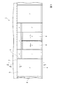
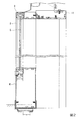
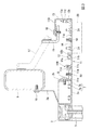
図1は、本発明の実施形態のサッシ用額縁が固定されるサッシの模式的な正面図である。図2は、図1におけるA−A断面図である。図3は、図1におけるB−B断面図である。
Embodiments of the present invention will be described below with reference to the accompanying drawings.
The sash frame of this embodiment will be described.
FIG. 1 is a schematic front view of a sash to which a sash frame according to an embodiment of the present invention is fixed. 2 is a cross-sectional view taken along line AA in FIG. 3 is a cross-sectional view taken along the line BB in FIG.
図1に本実施形態のサッシ用額縁が用いられる建築物1を示す。建築物1は、例えば、コンビニエンスストア等の建物に用いることができる。
建築物1は、正面に、上枠2(サッシの上枠)、上枠2と平行に延ばされた下枠4、および上枠2と下枠4とを連結する縦枠3等の枠材を含みフィックス窓を構成するサッシを備える。これらの枠材は、図示略の支持構造を介して図示略の躯体に支持されている。
図2に示すように、これら枠材には、パネル5が嵌め込まれている。パネル5を境にして、図示左側が室外、図示右側が室内になっている。
パネル5としては、例えば、ガラス、透明もしくは半透明樹脂板などを採用することができる。
図1に示すように、これらサッシの中央の開口部には、左右に開く一対のドア6が嵌め込まれている。
FIG. 1 shows a building 1 in which the sash frame of the present embodiment is used. The building 1 can be used for a building such as a convenience store, for example.
The building 1 has a frame such as an upper frame 2 (an upper frame of a sash), a
As shown in FIG. 2, a
As the
As shown in FIG. 1, a pair of
図3に、上枠2の近傍における室内側の断面構成を示す。
上枠2は、パネル5が嵌め込まれた上部から室内側に一定幅を有する枠体が、室内の上部の躯体9に沿って延ばされている。
上枠2の上部には、建築物1の躯体9に固定するための固定部2aが延ばされている。固定部2aは、ねじ10によって躯体9に固定されている。
上枠2の室内側には、下面が平滑な底面部2cと、底面部2cにおける最も室内側の端部から上方に立ち上げられ、上枠2の延在方向(図示紙面奥行き方向)に延ばされた壁部からなる額縁連結部2bと、が形成されている。
FIG. 3 shows a cross-sectional configuration on the indoor side in the vicinity of the
In the
A
On the indoor side of the
上枠2の額縁連結部2bには、後述する上枠額縁11の一端部を固定するための連結材7が固定されている。
連結材7は、上枠2に沿って延ばされ、延在方向に直交する断面が略L字状とされたアングル部材からなる。連結材7は、互いに直交する第1の板状部7aおよび第2の板状部7bを備える。
連結材7の第1の板状部7aは、額縁連結部2bに押し当てられた状態で、ねじ8により額縁連結部2bにねじ止めされている。
連結材7の第2の板状部7bは、底面部2cの下面よりもわずか上側となる位置で、額縁連結部2bから離れる水平方向に突き出されている。
A connecting
The connecting
The first plate-
The second plate-
上枠額縁11(サッシ用額縁)は、上枠2の延在方向に沿って、略一定の断面形状で延ばされた枠材である。上枠額縁11は、建築物1の室内において、上枠2を側方から覆うとともに、上枠2よりもさらに室内側に張り出す額縁構造を形成する部材である。
上枠額縁11は、例えば、アルミニウム合金製の押し出し材で形成することができる。
The upper frame frame 11 (sash frame) is a frame member that is extended in a substantially constant cross-sectional shape along the extending direction of the
The upper
上枠額縁11の下面には、重量物を被着部材として取り付けることができる。例えば、建築物1のパネル5の室内側にロールカーテンを配置するような場合には、ロールカーテンを収容するロールカーテン装置20(被着部材)を下方から取り付けることが可能である。
このため、上枠額縁11の内部には、例えば金属板などによる補強板14が配置されている。すなわち、補強板14は、例えばロールカーテン装置20などの重量物を固定するための下地として用いることができる。
補強板14の形状は、上枠額縁11を補強したり、下地として用いたりすることができる形状であれば、特に限定されない。図3に示す補強板14の一例は、一定幅の矩形断面が、図示奥行き方向に上枠額縁11と同程度の長さだけ延ばされた平板部材である。
A heavy object can be attached to the lower surface of the
Therefore, a reinforcing
The shape of the reinforcing
上枠額縁11は、底面部11A、係止部11B、室内側側面部11C、および上面部11Dを備える。
これら底面部11A、係止部11B、室内側側面部11C(側面部)、および上面部11Dは、上枠額縁11の延在方向の全体にわたって形成されており、いずれも、上枠2の延在方向に沿って延ばされている。
以下、上枠額縁11の構成について、上枠2に固定された状態における位置関係に基づいて説明する。このため、上枠額縁11において、上枠2の延在方向に直交する方向の相対的な位置関係を表す場合に、特に断らない限り、上枠2に近い方(図3における左の方)を「室外側」、上枠2から離れる方(図3における右の方)を「室内側」と称する。すなわち、この場合の「室外側」は「室内」における相対的な位置関係を示している。
The
The
Hereinafter, the configuration of the
底面部11Aは、上枠2の底面部2cと整列した平面部を、上枠2よりも室内側に形成するため、上枠額縁11の底部に設けられた板状部である。
底面部11Aの底面部下面11bは、平滑な平面からなり、上枠2への底面部2cの下面と水平に整列している。
底面部11Aの上面には、室外側から室内側に向かって、係止部11Bと底面タッピングホール部12(第1のタッピングホール部)とが、この順に形成されている。
底面部11Aの最も室内側の端部には、上方に延びる室内側側面部11Cが接続されている。
The
The bottom surface portion
On the upper surface of the
An indoor side surface portion 11C extending upward is connected to an end portion on the most indoor side of the
係止部11Bは、額縁連結部2bに固定された連結材7の第2の板状部7bに、上枠額縁11を係止するための形状部分であり、突起部11cと、押え部11dとを備える。
突起部11cは、第2の板状部7bに下方から当接するための形状部分である。突起部11cは、第2の板状部に重なる複数箇所において上枠額縁11の延在方向(図3の図示奥行き方向)に沿って延ばされた突条で構成されている。
押え部11dは、各突起部11c上に配置された第2の板状部7bの先端部を底面部11Aとの間で上方から覆って、底面部11Aとの間に挟持するように曲げられた板状部で構成されている。
The locking
The
The holding
底面タッピングホール部12は、上枠額縁11の延在方向の端部を固定するため上枠額縁11の延在方向の全体にわたって延ばされた凸状部である。
底面タッピングホール部12は、その内部に、延在方向に沿って延び、上方に開口するU字状の溝からなるタッピングホール12aが貫通されている。
底面タッピングホール部12の室内側の上端部には、より室内側に位置する室内側側面部11Cの方に向かって水平方向に突出された保持片部12b(第1の突起部)が形成されている。
保持片部12bと底面部11Aとの間には、補強板14が挿入可能な隙間があけられている。
保持片部12bと底面部11Aとの間の隙間、および底面タッピングホール部12の位置は、補強板14が底面部11Aに沿って挿入可能となるように決めておく。このため、保持片部12bは、底面タッピングホール部12の上端部には限らず、底面部11Aとの間の適宜の位置に形成することができる。
The bottom tapping
The bottom tapping
At the upper end of the bottom tapping
A gap into which the reinforcing
The gap between the holding
底面タッピングホール部12と室内側側面部11Cとの間の底面部11Aの上面は、平滑な平面からなり、補強板14を載置する載置面11aが形成されている。
底面部11Aには、載置面11aの範囲において、補強板14をねじ止めするねじ18を挿入するためのねじ穴が形成されている。
The upper surface of the
A screw hole for inserting a
室内側側面部11Cは、底面部11Aの最も室内側の端部から上方に向かって立ち上がる板状部であり、上枠額縁11の延在方向の全体にわたって延ばされている。
室内側側面部11Cにおいて、室外側に向いた内面には、底面部11Aの上方に突出された側面タッピングホール部13(第2のタッピングホール部)が設けられている。
The indoor
In the indoor side surface portion 11C, a side surface tapping hole portion 13 (second tapping hole portion) protruding above the
側面タッピングホール部13は、上枠額縁11の延在方向の端部を固定するため上枠額縁11の延在方向の全体にわたって延ばされた凸状部である。
側面タッピングホール部13は、その内部に、延在方向に沿って延び、室外側に開口するU字状の溝からなるタッピングホール13aが貫通されている。側面タッピングホール部13の突出方向の先端部には、底面部11A側の先端部から、底面部11Aの方に向かって鉛直方向に突出された保持片部13b(第2の突起部)が形成されている。
保持片部13bの突出方向の先端部と底面部11Aの載置面11aとの間には、補強板14が底面部11Aに沿って挿入可能な隙間があけられている。このため、保持片部13bは、底面タッピングホール部13の先端部には限らず、室内側側面部11Cとの間の適宜の位置に形成することができる。
The side surface tapping
The side surface tapping
A gap is formed between the front end portion of the holding
上面部11Dは、室内側側面部11Cの上端部から室外側に向かって水平方向に延ばされた板状部である。
The
このような構成の上枠額縁11を、建築物1に固定するには、まず、載置面11aと、保持片部12bおよび保持片部13bとの間に形成された隙間に、補強板14を挿入し、補強板14を載置面11aに載置する。
このとき、補強板14の幅方向の両端部は、底面タッピングホール部12の側面と、室内側側面部11Cとによってガイドされ、補強板14の上面は、保持片部12b、13bによってガイドされる。このため、上枠額縁11においては、補強板14が円滑に挿入される。
In order to fix the
At this time, both end portions in the width direction of the reinforcing
載置面11aに対する補強板14の位置決めを行ったら、底面部11Aに形成されたねじ穴を通して、下方からねじ18を挿入し、補強板14にねじ込む。これにより、補強板14の表面が、載置面11aに重なった状態で、底面部11Aに補強板14が固定される。
After positioning the reinforcing
次に、額縁連結部2bに固定された連結材7の第2の板状部7bの先端部に、係止部11Bの押え部11dを係止し、係止部11Bの突起部11cを第2の板状部7bの下面に当接させる。このとき、上面部11Dが、アングル15の上面に重なるようにする。これにより、上枠額縁11が連結材7およびアングル15に係止される。
このような係止状態では、上枠額縁11の室外側の端部は、連結材7に沿って位置決めされ、底面部11Aが、上枠2の底面部2cと整列する。
Next, the
In such a locked state, the end portion on the outdoor side of the
次に、隣り合う突起部11cの中間部の位置であって、第2の板状部7bと対向する位置において、下方から底面部11Aにねじ19を挿入し、ねじ19を第2の板状部7bにねじ込む。これにより、底面部11Aが連結材7に固定される。
また、上面部11Dの上方からねじ16を挿入し、ねじ16を第2の板状部7bにねじ込む。これにより、上面部11Dがアングル15に固定される。
このようにして、上枠額縁11が、上枠2に固定される。
上枠額縁11の端部は、縦枠3に接続された適宜の固定部材にねじを挿入して、タッピングホール12a、13aにねじ込んで固定する。
Next, the
Further, the
In this way, the
The end portion of the
このようにして固定された上枠額縁11は、底面部11A上に補強板14がねじ止めされているため、補強板14によって底面部11Aが補強される。
補強板14は、例えば、ロールカーテン装置20などの重量物を固定する下地として用いることが可能である。
例えば、底面部11Aの底面部下面11bに配置したロールカーテン装置20の取り付け穴に、下方からねじ21を挿入し、ねじ21を底面部11Aおよび補強板14にねじ込むことによって、ロールカーテン装置20を固定することができる。
Since the reinforcing
The reinforcing
For example, the
本実施形態の上枠額縁11によれば、側面タッピングホール部13を室内側側面部11Cから、底面部11Aの上方に突出するように設けている。これにより、上枠額縁11の端部を固定するため、水平方向に離間した2箇所に、タッピングホール12a、13aを設けることができる。
その際、側面タッピングホール部13は、底面部11Aの上方に突出しているため、底面部11Aの上面において、底面タッピングホール部12と室内側側面部11Cとの間には、平滑な載置面11aが形成されている。
この結果、上枠額縁11では、側面タッピングホール部13が邪魔になることなく、また側面タッピングホール部13の上を跨ぐことなく、底面タッピングホール部12と室内側側面部11Cとの間の全面にわたって補強板14を載置することができる。
このため、上枠額縁11では、底面タッピングホール部12と室内側側面部11Cとの間に他のタッピングホール部が形成されている場合に比べて、より広幅の補強板14を載置することができる。
これにより、上枠額縁11に用いる補強板14では、側面タッピングホール部13を避けるための幅および配置位置の制約が低減される。
このため、上枠額縁11によれば、補強板14を下地として用いる場合に、ロールカーテン装置20等の被着部材の取付位置の制限を低減することができる。
According to the
At that time, since the side surface tapping
As a result, in the
Therefore, in the
Thereby, in the
For this reason, according to the
なお、上記の実施形態の説明では、補強板14が平板部材の場合の例で説明したが、補強板14の断面形状は平板には限定されない。
補強板14の断面形状は、保持片部12b、13bと載置面11aとの間の隙間に挿入できる適宜の形状を採用することができる。例えば、補強板14の厚さが、保持片部12b、13bで挟まれる領域以外で、保持片部12b、13bよりも上方に突出するように変化していてもよい。
また、保持片部12b、13bと、載置面11aとの間の隙間は、保持片部12b、13bの位置を変えることで適宜変更することができる。
特に、保持片部13bの先端部と載置面11aとの距離は、側面タッピングホール部13の位置を適宜設定したり、保持片部13bの突出量を変えたりすることにより、室内側側面部11Cの高さの範囲で自由に設定することができる。
このため、保持片部13bの先端部と載置面11aとの隙間の大きさの自由度は、保持片部12bと11aとの隙間の大きさの自由度よりも大きい。
例えば、補強板14を、載置面11aに沿う平板部と、室内側側面部11Cの内面に沿う平板部とからなる断面L字状の部材で構成してもよい。
さらに、補強板14の長さも、上枠額縁11と同程度とすることは必須ではなく、上枠額縁11よりも短くして、上枠額縁11を部分的に補強するようにしてもよい。
In the above description of the embodiment, an example in which the reinforcing
As the cross-sectional shape of the reinforcing
Moreover, the clearance gap between holding
In particular, the distance between the tip of the holding
For this reason, the freedom degree of the magnitude | size of the clearance gap between the front-end | tip part of the holding
For example, you may comprise the
Furthermore, it is not essential that the length of the reinforcing
上記の実施形態の説明では、補強板14がねじ18によって底面部11Aに固定されている場合の例で説明したが、補強板14をねじ18によって固定することは必須ではない。
In the description of the above embodiment, the example in which the reinforcing
上記実施形態では、上枠額縁11が、底面タッピングホール部12と側面タッピングホール部13とを有する場合の例で説明したが、タッピングホール部の個数は、2つには限定されない。例えば、係止部11Bと底面タッピングホール部12との間、および側面タッピングホール部13と上面部11Dとの間に、他のタッピングホール部を適宜数設けることが可能である。
In the above embodiment, the
上記の実施形態で説明した構成要素は、本発明の技術的思想の範囲で適宜組み合わせたり、削除したりして実施することができる。 The components described in the above embodiments can be implemented by being appropriately combined or deleted within the scope of the technical idea of the present invention.
1 建築物
2 上枠(サッシの上枠)
11 上枠額縁(サッシ用額縁)
11a 載置面
11A 底面部
11B 係止部
11C 室内側側面部(側面部)
12 底面タッピングホール部(第1のタッピングホール部)
12b 保持片部(第1の突起部)
13 側面タッピングホール部(第2のタッピングホール部)
13b 保持片部(第2の突起部)
14 補強板
20 ロールカーテン装置(被着部材)
1
11 Upper frame picture frame (sash frame)
12 Bottom tapping hole (first tapping hole)
12b Holding piece (first protrusion)
13 Side tapping hole (second tapping hole)
13b Holding piece (second protrusion)
14
Claims (2)
前記上枠に沿って延ばされた底面部と、
該底面部の延在方向に直交する方向の端部から上方に延ばされるとともに、前記底面部の延在方向に沿って延ばされた側面部と、
前記底面部から上方に突出して設けられ、前記底面部の延在方向に沿って延ばされた第1のタッピングホール部と、
該第1のタッピングホール部において、前記側面部の方に突出された第1の突起部と、
前記側面部において、前記底面部の上方に突出して設けられ、前記底面部の延在方向に沿って延ばされた第2のタッピングホール部と、
該第2のタッピングホール部において、前記底面部の方に突出された第2の突起部と、
前記第1の突起部と前記底面部との間、および前記第2の突起部と前記底面部との間の隙間に挿入され、前記底面部の上面に載置された補強板と、
を備えることを特徴とするサッシ用額縁。 A sash frame attached to the upper frame of the sash,
A bottom surface portion extending along the upper frame;
A side surface portion extending upward from an end portion in a direction orthogonal to the extending direction of the bottom surface portion, and extending along the extending direction of the bottom surface portion;
A first tapping hole portion provided so as to protrude upward from the bottom surface portion and extending along the extending direction of the bottom surface portion;
A first protrusion protruding toward the side surface in the first tapping hole,
A second tapping hole portion provided in the side surface portion so as to protrude above the bottom surface portion and extend along the extending direction of the bottom surface portion;
A second protrusion protruding toward the bottom surface in the second tapping hole,
A reinforcing plate that is inserted in a gap between the first protrusion and the bottom surface, and between the second protrusion and the bottom surface, and is placed on the top surface of the bottom surface;
A sash frame characterized by comprising:
被着部材を前記底面部の下方からねじ止めするための下地として用いられる請求項1に記載のサッシ用額縁。 The reinforcing plate is
The sash frame according to claim 1, wherein the sash frame is used as a base for screwing the adherend member from below the bottom surface portion.
Priority Applications (1)
| Application Number | Priority Date | Filing Date | Title |
|---|---|---|---|
| JP2014221395A JP6297961B2 (en) | 2014-10-30 | 2014-10-30 | Sash frame |
Applications Claiming Priority (1)
| Application Number | Priority Date | Filing Date | Title |
|---|---|---|---|
| JP2014221395A JP6297961B2 (en) | 2014-10-30 | 2014-10-30 | Sash frame |
Publications (2)
| Publication Number | Publication Date |
|---|---|
| JP2016089367A true JP2016089367A (en) | 2016-05-23 |
| JP6297961B2 JP6297961B2 (en) | 2018-03-20 |
Family
ID=56018959
Family Applications (1)
| Application Number | Title | Priority Date | Filing Date |
|---|---|---|---|
| JP2014221395A Active JP6297961B2 (en) | 2014-10-30 | 2014-10-30 | Sash frame |
Country Status (1)
| Country | Link |
|---|---|
| JP (1) | JP6297961B2 (en) |
Citations (5)
| Publication number | Priority date | Publication date | Assignee | Title |
|---|---|---|---|---|
| US4250673A (en) * | 1979-05-25 | 1981-02-17 | Kawneer Company, Inc. | Window replacement system |
| JPS5670070U (en) * | 1979-11-05 | 1981-06-10 | ||
| JPS57161685U (en) * | 1981-04-07 | 1982-10-12 | ||
| JPS6195883U (en) * | 1985-02-02 | 1986-06-20 | ||
| JP2002235483A (en) * | 2001-02-08 | 2002-08-23 | Bunka Shutter Co Ltd | Door structure |
-
2014
- 2014-10-30 JP JP2014221395A patent/JP6297961B2/en active Active
Patent Citations (5)
| Publication number | Priority date | Publication date | Assignee | Title |
|---|---|---|---|---|
| US4250673A (en) * | 1979-05-25 | 1981-02-17 | Kawneer Company, Inc. | Window replacement system |
| JPS5670070U (en) * | 1979-11-05 | 1981-06-10 | ||
| JPS57161685U (en) * | 1981-04-07 | 1982-10-12 | ||
| JPS6195883U (en) * | 1985-02-02 | 1986-06-20 | ||
| JP2002235483A (en) * | 2001-02-08 | 2002-08-23 | Bunka Shutter Co Ltd | Door structure |
Also Published As
| Publication number | Publication date |
|---|---|
| JP6297961B2 (en) | 2018-03-20 |
Similar Documents
| Publication | Publication Date | Title |
|---|---|---|
| RU138236U1 (en) | DOOR DEVICE | |
| US8967227B2 (en) | Roller curtain fixing bracket assembly | |
| JP2009299440A (en) | Sash | |
| JP2009299437A (en) | Sash | |
| JP2008196115A (en) | Mounting device of entrance unit | |
| JP6297961B2 (en) | Sash frame | |
| JP2009299439A (en) | Sash | |
| JP5264809B2 (en) | Refurbishment sash | |
| CN208122600U (en) | Upper rail and shower house for shower house | |
| JP2013014879A (en) | Fitting | |
| JP3819007B2 (en) | Entrance equipment mounting equipment | |
| JP6680595B2 (en) | Window connection structure | |
| JP2016089543A (en) | Auxiliary member for solar shading device | |
| WO2019028688A1 (en) | Frame assembly and display device | |
| JP7057185B2 (en) | Interior fittings | |
| JP2012241355A (en) | Installation structure of frame peripheral member of opening device | |
| JP2008274686A (en) | Opening-closing window | |
| TWM529739U (en) | Adjustable door frame module | |
| KR20190018871A (en) | Window fram dividing bar set being easy to install and adjust position and dividing window prepared therefrom | |
| JP2009299438A (en) | Sash with flat sill | |
| JP5052395B2 (en) | Accessories for exterior panels | |
| JP2010116743A (en) | Fittings | |
| JP5220695B2 (en) | Refurbished sash unit and installation method of refurbished sash unit | |
| CN208430639U (en) | Inner corner trim splicing construction for integral bathroom sheet wall | |
| CN206299317U (en) | A kind of ventilation shutter and the rack using the ventilation shutter |
Legal Events
| Date | Code | Title | Description |
|---|---|---|---|
| A621 | Written request for application examination |
Free format text: JAPANESE INTERMEDIATE CODE: A621 Effective date: 20170629 |
|
| A977 | Report on retrieval |
Free format text: JAPANESE INTERMEDIATE CODE: A971007 Effective date: 20180214 |
|
| TRDD | Decision of grant or rejection written | ||
| A01 | Written decision to grant a patent or to grant a registration (utility model) |
Free format text: JAPANESE INTERMEDIATE CODE: A01 Effective date: 20180220 |
|
| A61 | First payment of annual fees (during grant procedure) |
Free format text: JAPANESE INTERMEDIATE CODE: A61 Effective date: 20180222 |
|
| R150 | Certificate of patent or registration of utility model |
Ref document number: 6297961 Country of ref document: JP Free format text: JAPANESE INTERMEDIATE CODE: R150 |
|
| S111 | Request for change of ownership or part of ownership |
Free format text: JAPANESE INTERMEDIATE CODE: R313111 |
|
| R350 | Written notification of registration of transfer |
Free format text: JAPANESE INTERMEDIATE CODE: R350 |