JP2016055152A - Cannula device - Google Patents
Cannula device Download PDFInfo
- Publication number
- JP2016055152A JP2016055152A JP2015075298A JP2015075298A JP2016055152A JP 2016055152 A JP2016055152 A JP 2016055152A JP 2015075298 A JP2015075298 A JP 2015075298A JP 2015075298 A JP2015075298 A JP 2015075298A JP 2016055152 A JP2016055152 A JP 2016055152A
- Authority
- JP
- Japan
- Prior art keywords
- tube
- ring
- cannula
- receiving portion
- connector
- Prior art date
- Legal status (The legal status is an assumption and is not a legal conclusion. Google has not performed a legal analysis and makes no representation as to the accuracy of the status listed.)
- Granted
Links
- 230000029058 respiratory gaseous exchange Effects 0.000 claims description 31
- 238000003780 insertion Methods 0.000 claims description 27
- 230000037431 insertion Effects 0.000 claims description 27
- 239000007789 gas Substances 0.000 description 34
- QVGXLLKOCUKJST-UHFFFAOYSA-N atomic oxygen Chemical compound [O] QVGXLLKOCUKJST-UHFFFAOYSA-N 0.000 description 10
- 239000001301 oxygen Substances 0.000 description 10
- 229910052760 oxygen Inorganic materials 0.000 description 10
- 210000000078 claw Anatomy 0.000 description 6
- 230000002093 peripheral effect Effects 0.000 description 6
- 230000000241 respiratory effect Effects 0.000 description 4
- 229920001971 elastomer Polymers 0.000 description 3
- 229920003002 synthetic resin Polymers 0.000 description 3
- 239000000057 synthetic resin Substances 0.000 description 3
- PPBRXRYQALVLMV-UHFFFAOYSA-N Styrene Chemical compound C=CC1=CC=CC=C1 PPBRXRYQALVLMV-UHFFFAOYSA-N 0.000 description 2
- 238000002560 therapeutic procedure Methods 0.000 description 2
- 206010007617 Cardio-respiratory arrest Diseases 0.000 description 1
- JOYRKODLDBILNP-UHFFFAOYSA-N Ethyl urethane Chemical compound CCOC(N)=O JOYRKODLDBILNP-UHFFFAOYSA-N 0.000 description 1
- 208000010496 Heart Arrest Diseases 0.000 description 1
- 239000000806 elastomer Substances 0.000 description 1
- 238000002664 inhalation therapy Methods 0.000 description 1
- 238000000034 method Methods 0.000 description 1
- 210000002345 respiratory system Anatomy 0.000 description 1
- 229920002379 silicone rubber Polymers 0.000 description 1
- 239000004945 silicone rubber Substances 0.000 description 1
Images

Classifications
-
- A—HUMAN NECESSITIES
- A61—MEDICAL OR VETERINARY SCIENCE; HYGIENE
- A61M—DEVICES FOR INTRODUCING MEDIA INTO, OR ONTO, THE BODY; DEVICES FOR TRANSDUCING BODY MEDIA OR FOR TAKING MEDIA FROM THE BODY; DEVICES FOR PRODUCING OR ENDING SLEEP OR STUPOR
- A61M16/00—Devices for influencing the respiratory system of patients by gas treatment, e.g. ventilators; Tracheal tubes
- A61M16/06—Respiratory or anaesthetic masks
- A61M16/0666—Nasal cannulas or tubing
- A61M16/0672—Nasal cannula assemblies for oxygen therapy
-
- A—HUMAN NECESSITIES
- A61—MEDICAL OR VETERINARY SCIENCE; HYGIENE
- A61M—DEVICES FOR INTRODUCING MEDIA INTO, OR ONTO, THE BODY; DEVICES FOR TRANSDUCING BODY MEDIA OR FOR TAKING MEDIA FROM THE BODY; DEVICES FOR PRODUCING OR ENDING SLEEP OR STUPOR
- A61M16/00—Devices for influencing the respiratory system of patients by gas treatment, e.g. ventilators; Tracheal tubes
- A61M16/06—Respiratory or anaesthetic masks
- A61M16/0666—Nasal cannulas or tubing
-
- A—HUMAN NECESSITIES
- A61—MEDICAL OR VETERINARY SCIENCE; HYGIENE
- A61M—DEVICES FOR INTRODUCING MEDIA INTO, OR ONTO, THE BODY; DEVICES FOR TRANSDUCING BODY MEDIA OR FOR TAKING MEDIA FROM THE BODY; DEVICES FOR PRODUCING OR ENDING SLEEP OR STUPOR
- A61M16/00—Devices for influencing the respiratory system of patients by gas treatment, e.g. ventilators; Tracheal tubes
- A61M16/08—Bellows; Connecting tubes ; Water traps; Patient circuits
- A61M16/0816—Joints or connectors
-
- A—HUMAN NECESSITIES
- A61—MEDICAL OR VETERINARY SCIENCE; HYGIENE
- A61M—DEVICES FOR INTRODUCING MEDIA INTO, OR ONTO, THE BODY; DEVICES FOR TRANSDUCING BODY MEDIA OR FOR TAKING MEDIA FROM THE BODY; DEVICES FOR PRODUCING OR ENDING SLEEP OR STUPOR
- A61M2202/00—Special media to be introduced, removed or treated
- A61M2202/02—Gases
- A61M2202/0208—Oxygen
Landscapes
- Health & Medical Sciences (AREA)
- Pulmonology (AREA)
- Emergency Medicine (AREA)
- Heart & Thoracic Surgery (AREA)
- Life Sciences & Earth Sciences (AREA)
- Biomedical Technology (AREA)
- Anesthesiology (AREA)
- Hematology (AREA)
- Engineering & Computer Science (AREA)
- Animal Behavior & Ethology (AREA)
- General Health & Medical Sciences (AREA)
- Public Health (AREA)
- Veterinary Medicine (AREA)
- Otolaryngology (AREA)
- Respiratory Apparatuses And Protective Means (AREA)
- Infusion, Injection, And Reservoir Apparatuses (AREA)
Abstract
Description
本発明は、酸素などの呼吸用気体を人体に供給する際に用いられるカニューラ装置に関する。 The present invention relates to a cannula device used when supplying a breathing gas such as oxygen to a human body.
従来から、所定量の酸素を含んだ呼吸用気体を患者の気道へ送る人工呼吸器や、酸素吸入療法のための装置が知られており、これらの装置から送られる呼吸用気体はカニューラ装置によって人体に供給される。このカニューラ装置は、人体の鼻孔に取り付けられる鼻孔カニューラに複数のチューブが接続された構成であり、そのチューブに人工呼吸器や酸素発生装置等の呼吸気体供給装置が接続される。 Conventionally, ventilators that send a breathing gas containing a predetermined amount of oxygen to the patient's respiratory tract and devices for oxygen inhalation therapy are known, and the breathing gas sent from these devices is sent by a cannula device. Supplied to the human body. This cannula device has a configuration in which a plurality of tubes are connected to a nostril cannula attached to a nostril of a human body, and a respiratory gas supply device such as a ventilator or an oxygen generator is connected to the tube.
従来、例えば特許文献1に示すカニューラ装置は、中空構造でフレキシブルな鼻孔カニューラと、この鼻孔カニューラの両端部にそれらの一端部をそれぞれ連結されている呼吸気体供給用チューブとしての左右一対のフレキシブルで比較的短い第1の酸素供給用チューブと、これら一対の第1の酸素供給用チューブの他端部を呼吸気体供給用チューブとしての一本のフレキシブルで比較的短い第2の酸素供給用チューブの一端部に連結しているフレキシブルなY字形コネクタと、第2の酸素供給用チューブの他端部に取り付けられているコネクタとを備えている。このコネクタは、第3の酸素供給用チューブの端部のコネクタが着脱される。第3の酸素供給用チューブは、比較的長いフレキシブルな呼吸気体供給用チューブであり、呼吸気体供給装置に接続される。 Conventionally, for example, a cannula device shown in Patent Document 1 is a hollow structure flexible nostril cannula and a pair of left and right flexible as a breathing gas supply tube having one end connected to both ends of the nostril cannula. A relatively short first oxygen supply tube and one flexible and relatively short second oxygen supply tube having the other end of the pair of first oxygen supply tubes as a breathing gas supply tube. A flexible Y-shaped connector connected to one end and a connector attached to the other end of the second oxygen supply tube are provided. The connector at the end of the third oxygen supply tube is attached to and detached from this connector. The third oxygen supply tube is a relatively long flexible breathing gas supply tube and is connected to the breathing gas supply device.
このようなカニューラ装置において、鼻孔カニューラ側のコネクタと呼吸気体供給装置側の供給チューブ先端のコネクタとが着脱されるが、接続ミス等により不用意に脱落しないようにする必要がある。患者が心肺停止状態である場合などに呼吸用気体を人体に強制的に供給する場合や、近年注目されているハイフロー療法(患者の呼気よりも高い流量で呼吸用気体を供給する療法)においては、通常よりも高流量で呼吸用気体が人体に供給されるが、このような高流量の呼吸用気体を供給する場合に、特に抜け止めを確実にする必要がある。反面、緊急時には簡単に脱着できることが望まれる。 In such a cannula device, the connector on the nostril cannula side and the connector on the tip of the supply tube on the breathing gas supply device side are attached and detached, but it is necessary to prevent them from being inadvertently dropped due to a connection error or the like. In cases where the patient is forced to supply breathing gas to the human body, such as when the patient is in cardiopulmonary arrest, or in high-flow therapy (therapy that supplies breathing gas at a higher flow rate than the patient's exhalation) that has been attracting attention in recent years The breathing gas is supplied to the human body at a flow rate higher than usual, but when such a high flow rate breathing gas is supplied, it is particularly necessary to make sure that it does not come off. On the other hand, it is desirable that it can be easily detached in an emergency.
本発明は、このような事情に鑑みてなされたもので、鼻孔カニューラのチューブと呼吸気体供給装置側の供給チューブとの着脱を容易かつ確実にしたカニューラ装置を提供することを目的とする。 This invention is made | formed in view of such a situation, and it aims at providing the cannula apparatus which attached and detached easily and reliably with the tube of a nostril cannula and the supply tube by the side of a breathing gas supply apparatus.
本発明に係るカニューラ装置は、人体の鼻孔に装着される一対の鼻孔管を有する鼻孔カニューラと、該鼻孔カニューラに接続固定され前記鼻孔管に連通する一対の呼吸用気体流通用チューブと、これら呼吸用気体流通用チューブの各端部に接続固定されたアダプタ管と、該アダプタ管に着脱自在に接続されるコネクタ管と、該コネクタ管に接続固定された呼吸用気体供給用チューブとを備え、前記アダプタ管および前記コネクタ管は、いずれか一方が受入部を有する雌部材、他方が挿入部を有する雄部材として、互いに挿脱自在に設けられ、前記挿入部の基端部の外面に設けられ、周方向全周に延びる突条または凹溝からなるリング状部と、前記受入部に設けられ、該受入部に挿入された前記挿入部の前記リング状部を係止する突起部を有するロック片とを有する。 A cannula device according to the present invention includes a nostril cannula having a pair of nostril tubes attached to a nostril of a human body, a pair of breathing gas flow tubes connected to and fixed to the nostril cannula and communicating with the nostril tube, and An adapter tube connected and fixed to each end of the gas distribution tube, a connector tube detachably connected to the adapter tube, and a breathing gas supply tube connected and fixed to the connector tube, The adapter tube and the connector tube are provided so that either one of them is a female member having a receiving portion, and the other is a male member having an insertion portion, and is detachably provided on the outer surface of the base end portion of the insertion portion. A ring-shaped portion formed of a ridge or a groove extending in the entire circumference in the circumferential direction, and a protrusion provided on the receiving portion and locking the ring-shaped portion of the insertion portion inserted into the receiving portion. And a lock piece.
コネクタ管とアダプタ管とのうちの一方を雌部材(受入部)、他方を雄部材(挿入部)として、雄部材を雌部材に挿入した状態でリング状部およびロック片が互いに係止されることにより、コネクタ管とアダプタ管との接続状態を維持することができる。この場合、ロック片と係止されるリング状部は、周方向に沿って形成されるので、コネクタ管とアダプタ管との周方向の位置関係にかかわらず、コネクタ管とアダプタ管とを確実にロック状態とすることができる。したがって、コネクタ管とアダプタ管とを接続する際に、その周方向の向きを意識することなく挿入するだけでよく、簡単である。 One of the connector tube and the adapter tube is a female member (receiving portion) and the other is a male member (inserting portion), and the ring-shaped portion and the locking piece are locked together with the male member inserted into the female member. Thus, the connection state between the connector pipe and the adapter pipe can be maintained. In this case, since the ring-shaped portion that is locked to the lock piece is formed along the circumferential direction, the connector pipe and the adapter pipe can be securely connected regardless of the circumferential positional relationship between the connector pipe and the adapter pipe. It can be in a locked state. Therefore, when connecting the connector pipe and the adapter pipe, it is only necessary to insert the connector pipe and the adapter pipe without being aware of the direction in the circumferential direction.
なお、コネクタ管とアダプタ管とは、いずれを挿入部(雄部材)で、いずれを受入部(雌部材)とするかは任意であり、ロック片は、その雌部材(受入部)の外面に設けられていればよい。 The connector pipe and the adapter pipe can be either an insertion part (male member) or a receiving part (female member), and the lock piece is formed on the outer surface of the female member (receiving part). What is necessary is just to be provided.
本発明のカニューラ装置において、前記リング状部が突条からなる場合、前記ロック片は、前記受入部の外面に固定されたヒンジ軸を介して回動自在に支持されるとともに、前記受入部の前記外面の一部に沿う円弧状に形成されており、前記突起部は、半径方向内方に突出して形成され、前記挿入部が前記受入部に挿入された状態において、前記突条からなる前記リング状部よりも前記挿入部の前記基端部側に位置するとよい。 In the cannula device of the present invention, when the ring-shaped portion is formed of a protrusion, the lock piece is rotatably supported via a hinge shaft fixed to the outer surface of the receiving portion, and It is formed in an arc shape along a part of the outer surface, and the protrusion is formed to protrude radially inward, and the insertion portion is inserted into the receiving portion, and includes the protrusion. It is good to be located in the base end part side of the insertion part rather than a ring-shaped part.
あるいは、本発明のカニューラ装置において、前記リング状部が凹溝からなる場合、前記ロック片は、前記受入部の外面に固定されたヒンジ軸を介して回動自在に支持されるとともに、前記受入部の前記外面の一部に沿う円弧状に形成されており、前記突起部は、半径方向内方に突出して形成され、前記挿入部が前記受入部に挿入された状態において、前記凹溝からなる前記リング状部内にはまり込むとよい。 Alternatively, in the cannula device of the present invention, when the ring-shaped portion is formed of a concave groove, the lock piece is rotatably supported via a hinge shaft fixed to the outer surface of the receiving portion, and the receiving portion Formed in a circular arc shape along a part of the outer surface of the portion, the protrusion is formed to protrude radially inward, and the insertion portion is inserted into the receiving portion from the concave groove. It is good to fit in the said ring-shaped part.
この場合、円弧状のロック片を、ヒンジ軸を中心に開閉する操作によってコネクタ管とアダプタ管との接続状態のロックおよびその解除をすることができ、操作性がよい。 In this case, the connection state between the connector pipe and the adapter pipe can be locked and released by an operation of opening and closing the arc-shaped lock piece around the hinge axis, and the operability is good.
本発明のカニューラ装置において、前記受入部の外面に、前記リング状部を係止した状態に前記ロック片を固定する係止部が設けられているとよい。 In the cannula device of the present invention, it is preferable that a locking portion for fixing the lock piece in a state where the ring-shaped portion is locked is provided on the outer surface of the receiving portion.
ロック片を固定する係止部を設けることで、アダプタ管とコネクタ管との接続状態を維持することができ、通常よりも高流量で呼吸用気体が人体に供給される場合にも、抜け止めを確実にすることができる。 By providing a locking part to fix the lock piece, the connection between the adapter tube and the connector tube can be maintained, and even when breathing gas is supplied to the human body at a higher flow rate than usual, it prevents it from coming off Can be ensured.
本発明のカニューラ装置によれば、アダプタ管とコネクタ管との着脱時に、その周方向の向きを意識する必要がなく着脱が容易である、また、ロック片でアダプタ管とコネクタ管とを係止することで、鼻孔カニューラと呼吸用気体供給用チューブとを接続した状態を確実に維持することができる。 According to the cannula device of the present invention, when attaching and detaching the adapter tube and the connector tube, it is not necessary to be aware of the direction of the circumferential direction, and the attachment and detachment is easy. By doing so, the state where the nostril cannula and the breathing gas supply tube are connected can be reliably maintained.
以下、本発明に係るカニューラ装置の実施形態を、図面を参照しながら説明する。
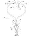
図1および図2に示すように、カニューラ装置1は、患者の鼻孔に装着される一対の鼻孔管2を有する鼻孔カニューラ3と、鼻孔カニューラ3に接続固定され鼻孔管2に連通する一対の呼吸用気体流通用チューブ4と、これら呼吸用気体流通用チューブ4の各端部に接続固定されたアダプタ管6(雄部材)と、アダプタ管6に着脱自在に接続されるコネクタ管7A(雌部材)と、このコネクタ管7Aに接続固定された呼吸用気体供給用チューブ7と、コネクタ管7Aの外面に回動自在に支持されたロックドア(ロック片)9と、鼻孔カニューラ3を患者の頭部に固定するための固定用部材13とを備える。
Hereinafter, embodiments of a cannula apparatus according to the present invention will be described with reference to the drawings.
As shown in FIGS. 1 and 2, a cannula device 1 includes a
鼻孔カニューラ3は、図1の上方に向けて設けられた鼻孔管2と、これら鼻孔管2を挟んで左右両端部に設けられ各鼻孔管2に連通して開口する接続端部5とを有し、患者に装着されたときに顔の表面に沿うように、左右方向の中央部(鼻孔管2近傍)が屈曲して形成されている。鼻孔カニューラ3は、全体がスチレン系エラストマー、シリコンゴム、ウレタン等、軟質の合成樹脂によって形成されている。
The
呼吸用気体流通用チューブ4は、各一端が鼻孔カニューラ3の接続端部5にそれぞれ接続されており、各他端がアダプタ管6に接続されている。呼吸用気体流通用チューブ4としては、汎用品のノーマルチューブもしくは、折れ曲がっても閉塞しにくいようにチューブ内面の長手方向に沿ってリブが設けてあるノンクラッシュチューブのいずれも使用することができる。
One end of each breathing
固定用部材13は、2本の呼吸用気体流通用チューブ4それぞれに装着されている一対のブラケット20に係止されている。固定用部材13は、本実施形態ではゴム紐を使用している。このゴム紐は、先端部13Aが細い棒状に固められており、本体部13Bは帯紐状で伸縮性を有している。
The
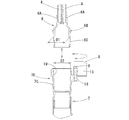
本実施形態では、アダプタ管6およびコネクタ管7Aは、コネクタ管7Aが受入部7Cを有する雌部材、アダプタ管6が挿入部6Cを有する雄部材として、互いに挿脱自在に設けられている。
In this embodiment, the
アダプタ管6は、図3に示すように、2本の呼吸用気体流通用チューブ4がそれぞれ接続される一対の導入管6Aと、これら導入管6Aに連通して開口する略円筒状の挿入部6Cとが一体に硬質な合成樹脂によって形成されたものであり、2本の呼吸用気体流通用チューブ4の各流路を、1本の呼吸用気体供給用チューブ7の流路に接続する。
As shown in FIG. 3, the
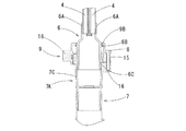
アダプタ管6の挿入部6Cの外面は、先端部に向かうにしたがって漸次縮径し、長さ方向途中位置の外径D1が受入部7Cの先端開口の内径D2と同寸法であるテーパー状に形成されている。挿入部6Cの基端部には、フランジ状に拡径する、周方向全周に延びる突条からなるリング状部6Bが一体に形成されている。
The outer surface of the
アダプタ管6に対して着脱自在に接続されるコネクタ管7Aは、全体が屈曲自在かつ伸縮自在な蛇腹状の呼吸器用気体供給用チューブ7の先端に接続固定されている。コネクタ管7Aは、硬質な合成樹脂によって形成されており、図2および図3に示すように、アダプタ管6の挿入部6Cを受け入れる略円筒状の受入部7Cと、受入部7C外面にロックドア9を回動可能に支持する支持部16と、ロックドア9がアダプタ管6のリング状部6Bの一部を覆ったときにロックドア9の端部を係止する係止部14A(図5参照)とを含む。
A
受入部7Cは、アダプタ管6の挿入部6Cを全方位受け入れ可能、すなわち互いの回転位置に関わらず挿入可能なテーパー状の内周面19を有する。受入部7Cの先端開口の内径D2と挿入部6Cのテーパー状部分の長さ方向途中位置の外径D1とが同寸法とされていることで、アダプタ管6とコネクタ管7Aとがより確実に気密に接続され、呼吸用気体の漏れなどの発生を防止することができる。
The receiving
支持部16には、軸方向と平行なヒンジ軸8が固定されている。例えば、本実施形態では、ヒンジ軸8の上端部を突出させた状態で下端部を固定している。
A
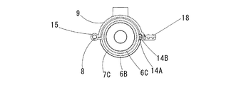
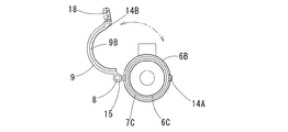
ロックドア9は、図4〜図6に示すように、全体として受入部7Cの外径よりわずかに大きい内径の円弧板状に形成され、周方向一方の端部に設けられヒンジ軸8を挿通させる貫通孔15と、周方向他方の先端部から内向きに突出するように設けられた係止爪14Bと、係止爪14Bの外側に設けられたつまみ部18と、周方向に沿って上縁部から半径方向内方に突出する突起部9Bとを有する。
As shown in FIGS. 4 to 6, the
突起部9Bは、図4に示すように、ロックドア9の縦断面においてL字の鈎状をなし、アダプタ管6の挿入部6Cがコネクタ管7Aの受入部7Cに挿入されたときに、挿入部6Cのリング状部6Bよりもアダプタ管6の基端側に配設されるように、すなわち突起部9Bと受入部7Cの開口端との間にリング状部6Bが位置する関係に設定されている。
As shown in FIG. 4, the protruding
次に、アダプタ管6とコネクタ管7Aとを接続する手順について説明する。図3には、アダプタ管6とコネクタ管7Aとを非接続状態とし、ロックドア9を開放した状態の縦断面図を示している。図5は、ロックドア9を閉鎖した状態の図1のB−B線に沿う断面矢視図である。図6は、ロックドア9を開放した状態の断面図を示している。
Next, a procedure for connecting the
まずロックドア9を開放した状態で、アダプタ管6の挿入部6Cを、コネクタ管7Aの受入部7Cに挿入する(図6)。このとき、挿入部6Cの外径D1の位置が受入部7Cに完全に入る位置まで挿入する。次にロックドア9を回動させて、突起部9Bをリング状部6Bの基端側に配置して円弧板状部が挿入部6Cの外周面の一部を覆った状態とし、受入部7Cの外周面に設けられた係止部14Aにロックドア9の係止爪14Bを係止させ、ロックドア9が回動しないように固定する(図5)。ロックドア9を固定すると、ロックドア9の突起部9Bがアダプタ管6のリング状部6Bの上面側に重なるように配置され、アダプタ管6を抜け止めすることができる。
First, with the
ロックドア9の突起部9Bは半径方向内方に突出し、アダプタ管6のリング状部6Bは周方向に沿って全周にわたり形成されているので、コネクタ管7Aとアダプタ管6との周方向の位置関係にかかわらず挿入でき、確実にロック状態とすることができる。したがって、これらを接続する際にその周方向の向きを意識することなく、アダプタ管6をコネクタ管7Aに挿入すればよく、着脱が非常に簡単である。
The
また、係止部14Aと係止爪14Bとによって、ロックドア9が受入部7Cに対して固定されるので、アダプタ管6とコネクタ管7Aとの接続状態を維持することができ、通常よりも高流量で呼吸用気体が人体に供給されて管内が高圧となる場合にも、抜け止めを確実にすることができる。
Further, since the
なお、本発明は前記実施形態の構成のものに限定されるものではなく、細部構成においては、本発明の趣旨を逸脱しない範囲において種々の変更を加えることが可能である。 In addition, this invention is not limited to the thing of the structure of the said embodiment, In a detailed structure, it is possible to add a various change in the range which does not deviate from the meaning of this invention.
前記実施形態では、アダプタ管6をコネクタ管7Aに挿入したが、鼻孔カニューラ側のアダプタ管を雌部材、呼吸用気体供給用チューブ側のコネクタ管を雄部材として、コネクタ管をアダプタ管に挿入する形態でもよい。
In the above embodiment, the
前記実施形態では、アダプタ管6のリング状部6Bを、挿入部6Cの外面から突出するリング状に形成したが、挿入部6Cの外面から陥没する凹溝状としてもよい。
In the embodiment, the ring-shaped
前記実施形態では、ロックドア(ロック片)9を円弧板状に形成したが、円弧の棒状で形成してもよい、さらに必ずしも円弧状でなくてもよく、リング状部を係止できる形状であればよい。 In the above embodiment, the lock door (lock piece) 9 is formed in an arc plate shape, but may be formed in an arc bar shape, and may not necessarily be in an arc shape, but in a shape that can lock the ring-shaped portion. I just need it.
前記実施形態では、ロックドア(ロック片)9の係止爪14Bを係止する係止部14Aを設けたが、ロック片の係止構造はその形態に限定するものではなく、例えば、ロック片の周方向長さを受入部の外周面の半分よりも若干大きくし、ロック片を弾性変形可能に形成することにより、その弾性力で受入部の外周面に係止する形態としてもよい。
In the above embodiment, the locking
1 カニューラ装置
2 鼻孔管
3 鼻孔カニューラ
4 呼吸用気体流通用チューブ
5 接続端部
6 アダプタ管
6A 導入管
6B リング状部
6C 挿入部
7 呼吸用気体供給用チューブ
7A コネクタ管
7C 受入部
8 ヒンジ軸
9 ロックドア(ロック片)
9B 突起部
13 固定用部材
13A 先端部
13B 本体部
14A 係止部
14B 係止爪
15 貫通孔
16 支持部
18 つまみ部
19 内周面
20 ブラケット
DESCRIPTION OF SYMBOLS 1
Claims (4)
該鼻孔カニューラに接続固定され前記鼻孔管に連通する一対の呼吸用気体流通用チューブと、
これら呼吸用気体流通用チューブの各端部に接続固定されたアダプタ管と、
該アダプタ管に着脱自在に接続されるコネクタ管と、
該コネクタ管に接続固定された呼吸用気体供給用チューブと
を備え、
前記アダプタ管および前記コネクタ管は、いずれか一方が受入部を有する雌部材、他方が挿入部を有する雄部材として、互いに挿脱自在に設けられ、
前記挿入部の基端部の外面に設けられ、周方向全周に延びる突条または凹溝からなるリング状部と、
前記受入部に設けられ、該受入部に挿入された前記挿入部の前記リング状部を係止する突起部を有するロック片と
を有することを特徴とするカニューラ装置。 A nostril cannula having a pair of nostril tubes attached to the nostrils of the human body;
A pair of breathing gas flow tubes connected to and fixed to the nostril cannula and communicating with the nostril tube;
An adapter tube connected and fixed to each end of these breathing gas flow tubes;
A connector tube detachably connected to the adapter tube;
A breathing gas supply tube connected and fixed to the connector tube,
The adapter tube and the connector tube are provided so that either one of them is a female member having a receiving portion, and the other is a male member having an insertion portion so as to be detachable from each other.
A ring-shaped portion that is provided on the outer surface of the base end portion of the insertion portion and includes a ridge or a groove extending in the entire circumferential direction; and
A cannula device comprising: a locking piece provided at the receiving portion and having a projection portion for locking the ring-shaped portion of the insertion portion inserted into the receiving portion.
前記ロック片は、前記受入部の外面に固定されたヒンジ軸を介して回動自在に支持されるとともに、前記受入部の前記外面の一部に沿う円弧状に形成されており、
前記突起部は、半径方向内方に突出して形成され、前記挿入部が前記受入部に挿入された状態において、前記リング状部よりも前記挿入部の前記基端部側に位置する
ことを特徴とする請求項1に記載のカニューラ装置。 The ring-shaped part is the protrusion,
The lock piece is rotatably supported via a hinge shaft fixed to the outer surface of the receiving portion, and is formed in an arc shape along a part of the outer surface of the receiving portion,
The protrusion is formed to protrude inward in the radial direction, and is positioned closer to the base end side of the insertion portion than the ring-shaped portion in a state where the insertion portion is inserted into the receiving portion. The cannula device according to claim 1.
前記ロック片は、前記受入部の外面に固定されたヒンジ軸を介して回動自在に支持されるとともに、前記受入部の前記外面の一部に沿う円弧状に形成されており、
前記突起部は、半径方向内方に突出して形成され、前記挿入部が前記受入部に挿入された状態において、前記リング状部内にはまり込む
ことを特徴とする請求項1に記載のカニューラ装置。 The ring-shaped part is the concave groove,
The lock piece is rotatably supported via a hinge shaft fixed to the outer surface of the receiving portion, and is formed in an arc shape along a part of the outer surface of the receiving portion,
2. The cannula apparatus according to claim 1, wherein the protrusion is formed to protrude inward in a radial direction, and fits into the ring-shaped portion in a state where the insertion portion is inserted into the receiving portion.
Applications Claiming Priority (2)
| Application Number | Priority Date | Filing Date | Title |
|---|---|---|---|
| JP2014181179 | 2014-09-05 | ||
| JP2014181179 | 2014-09-05 |
Publications (2)
| Publication Number | Publication Date |
|---|---|
| JP2016055152A true JP2016055152A (en) | 2016-04-21 |
| JP6305369B2 JP6305369B2 (en) | 2018-04-04 |
Family
ID=55436505
Family Applications (1)
| Application Number | Title | Priority Date | Filing Date |
|---|---|---|---|
| JP2015075298A Expired - Fee Related JP6305369B2 (en) | 2014-09-05 | 2015-04-01 | Cannula equipment |
Country Status (4)
| Country | Link |
|---|---|
| US (1) | US10342946B2 (en) |
| JP (1) | JP6305369B2 (en) |
| KR (1) | KR102397804B1 (en) |
| TW (1) | TWI661845B (en) |
Families Citing this family (10)
| Publication number | Priority date | Publication date | Assignee | Title |
|---|---|---|---|---|
| KR101865495B1 (en) * | 2017-01-02 | 2018-06-07 | 인제대학교 산학협력단 | Anti-separating apparatus of infusion set connection catheter |
| WO2019038662A1 (en) * | 2017-08-23 | 2019-02-28 | Fisher & Paykel Healthcare Limited | Respiratory mask system |
| USD878549S1 (en) | 2017-11-21 | 2020-03-17 | Fisher & Paykel Healthcare Limited | Connector for nasal cannula assembly |
| USD849242S1 (en) | 2017-11-21 | 2019-05-21 | Fisher & Paykel Healthcare Limited | Nasal cannula assembly |
| CN112007247B (en) * | 2019-05-28 | 2023-04-25 | 上海潓美医疗科技有限公司 | Wearable breathing circuit system and breathing apparatus having breathing circuit system |
| USD1034960S1 (en) * | 2020-04-10 | 2024-07-09 | Shanghai Asclepius Meditec Co., Ltd. | Nasal cannula assembly |
| USD1025347S1 (en) * | 2020-04-24 | 2024-04-30 | Intersurgical Ag | Nasal cannula assembly |
| KR102346304B1 (en) | 2021-05-13 | 2022-01-03 | 주식회사 토르 드라이브 | Sensor fusion-based object detection system and method especially for big-size or complex shape object |
| KR102711668B1 (en) | 2022-01-19 | 2024-09-27 | 이승협 | Fixing kit for nasal cannula and manufacturing method of band unit |
| KR20250170408A (en) | 2024-05-28 | 2025-12-05 | 건양대학교산학협력단 | Oxygen supply device |
Citations (7)
| Publication number | Priority date | Publication date | Assignee | Title |
|---|---|---|---|---|
| JPS6426318A (en) * | 1987-04-28 | 1989-01-27 | Kitagawa Ind Co Ltd | Corrugated pipe connector |
| US5620427A (en) * | 1995-04-27 | 1997-04-15 | David R. Kipp | Luer lock system |
| JP2003507687A (en) * | 1999-08-21 | 2003-02-25 | フレクサ ゲゼルシャフト ミット ベシュレンクテル ハフツング ウント コンパニー コマンディートゲゼルシャフト | Fixed coupling for corrugated tubes |
| JP2006518231A (en) * | 2003-02-21 | 2006-08-10 | レスメド リミテッド | Nasal assembly |
| JP2008163976A (en) * | 2006-12-27 | 2008-07-17 | Togo Seisakusho Corp | connector |
| US20130249211A1 (en) * | 2012-03-21 | 2013-09-26 | Tsai-Chen Yang | Quick connector |
| JP2013208206A (en) * | 2012-03-30 | 2013-10-10 | Daiken Iki Kk | Connection member |
Family Cites Families (8)
| Publication number | Priority date | Publication date | Assignee | Title |
|---|---|---|---|---|
| US4723948A (en) * | 1986-11-12 | 1988-02-09 | Pharmacia Nu Tech | Catheter attachment system |
| DE69529441T2 (en) * | 1994-07-29 | 2003-09-11 | Tyco International (Us) Inc., Exeter | Connection device for a catheter sleeve |
| US6776162B2 (en) * | 2000-03-13 | 2004-08-17 | Innomed Technologies, Inc. | Ventilation interface for sleep apnea therapy |
| SE524585C2 (en) * | 2002-03-04 | 2004-08-31 | Aba Sweden Ab | Pipe coupling device comprising two articulated halves |
| AU2004266693B2 (en) * | 2003-08-18 | 2011-03-10 | Breathe Technologies, Inc | Method and device for non-invasive ventilation with nasal interface |
| US9468730B2 (en) * | 2006-02-06 | 2016-10-18 | Lazarus Medical, LLC | Ventilator to tracheotomy tube coupling |
| JP5469934B2 (en) | 2009-07-07 | 2014-04-16 | アトムメディカル株式会社 | Nostril cannula device and mouth mask device |
| US9561359B2 (en) * | 2013-07-29 | 2017-02-07 | Iris Way | Medical connector assembly |
-
2015
- 2015-04-01 JP JP2015075298A patent/JP6305369B2/en not_active Expired - Fee Related
- 2015-06-01 TW TW104117636A patent/TWI661845B/en not_active IP Right Cessation
- 2015-06-02 US US14/728,096 patent/US10342946B2/en not_active Expired - Fee Related
- 2015-07-01 KR KR1020150094051A patent/KR102397804B1/en not_active Expired - Fee Related
Patent Citations (7)
| Publication number | Priority date | Publication date | Assignee | Title |
|---|---|---|---|---|
| JPS6426318A (en) * | 1987-04-28 | 1989-01-27 | Kitagawa Ind Co Ltd | Corrugated pipe connector |
| US5620427A (en) * | 1995-04-27 | 1997-04-15 | David R. Kipp | Luer lock system |
| JP2003507687A (en) * | 1999-08-21 | 2003-02-25 | フレクサ ゲゼルシャフト ミット ベシュレンクテル ハフツング ウント コンパニー コマンディートゲゼルシャフト | Fixed coupling for corrugated tubes |
| JP2006518231A (en) * | 2003-02-21 | 2006-08-10 | レスメド リミテッド | Nasal assembly |
| JP2008163976A (en) * | 2006-12-27 | 2008-07-17 | Togo Seisakusho Corp | connector |
| US20130249211A1 (en) * | 2012-03-21 | 2013-09-26 | Tsai-Chen Yang | Quick connector |
| JP2013208206A (en) * | 2012-03-30 | 2013-10-10 | Daiken Iki Kk | Connection member |
Also Published As
| Publication number | Publication date |
|---|---|
| KR20160029645A (en) | 2016-03-15 |
| TW201609208A (en) | 2016-03-16 |
| US10342946B2 (en) | 2019-07-09 |
| KR102397804B1 (en) | 2022-05-12 |
| JP6305369B2 (en) | 2018-04-04 |
| US20160067440A1 (en) | 2016-03-10 |
| TWI661845B (en) | 2019-06-11 |
Similar Documents
| Publication | Publication Date | Title |
|---|---|---|
| JP6305369B2 (en) | Cannula equipment | |
| US20220126051A1 (en) | Swivel elbow and connector assembly for patient interface systems | |
| US8997745B2 (en) | Tracheostomy tube combination radial snap and bayonet cannula connector | |
| EP1981599B1 (en) | Ventilator to tracheotomy tube coupling | |
| CN104519937B (en) | For the compressible connector of internal prongs | |
| US9265906B2 (en) | Compressible cannula connector with release grip | |
| JP2005514121A (en) | Medical connector for respiratory assembly | |
| CN103930149A (en) | Patient interface with snap-fit connector | |
| JP2018507741A (en) | Tracheostomy tube assembly | |
| JP2017513624A (en) | Fitting, tracheostomy tube and airway system | |
| JP6719126B2 (en) | Tracheostomy tube | |
| CN215231580U (en) | Breathing machine adapter | |
| RU2426562C2 (en) | Tracheostomic tube in assembly | |
| JP7078957B2 (en) | Tracheostomy tube with side holes that can be opened and closed freely | |
| DK3113820T3 (en) | Tracheal cannula inner tube | |
| JP2008125809A (en) | Connector structure, connecter member having the same, temperature/humidity exchanger for respiration, elbow member and tracheal tube |
Legal Events
| Date | Code | Title | Description |
|---|---|---|---|
| A621 | Written request for application examination |
Free format text: JAPANESE INTERMEDIATE CODE: A621 Effective date: 20160802 |
|
| A131 | Notification of reasons for refusal |
Free format text: JAPANESE INTERMEDIATE CODE: A131 Effective date: 20170425 |
|
| A977 | Report on retrieval |
Free format text: JAPANESE INTERMEDIATE CODE: A971007 Effective date: 20170428 |
|
| A521 | Request for written amendment filed |
Free format text: JAPANESE INTERMEDIATE CODE: A523 Effective date: 20170609 |
|
| A02 | Decision of refusal |
Free format text: JAPANESE INTERMEDIATE CODE: A02 Effective date: 20171017 |
|
| A521 | Request for written amendment filed |
Free format text: JAPANESE INTERMEDIATE CODE: A523 Effective date: 20171226 |
|
| A911 | Transfer to examiner for re-examination before appeal (zenchi) |
Free format text: JAPANESE INTERMEDIATE CODE: A911 Effective date: 20180105 |
|
| A131 | Notification of reasons for refusal |
Free format text: JAPANESE INTERMEDIATE CODE: A131 Effective date: 20180206 |
|
| A521 | Request for written amendment filed |
Free format text: JAPANESE INTERMEDIATE CODE: A523 Effective date: 20180221 |
|
| TRDD | Decision of grant or rejection written | ||
| A01 | Written decision to grant a patent or to grant a registration (utility model) |
Free format text: JAPANESE INTERMEDIATE CODE: A01 Effective date: 20180306 |
|
| A61 | First payment of annual fees (during grant procedure) |
Free format text: JAPANESE INTERMEDIATE CODE: A61 Effective date: 20180306 |
|
| R150 | Certificate of patent or registration of utility model |
Ref document number: 6305369 Country of ref document: JP Free format text: JAPANESE INTERMEDIATE CODE: R150 |
|
| R250 | Receipt of annual fees |
Free format text: JAPANESE INTERMEDIATE CODE: R250 |
|
| R250 | Receipt of annual fees |
Free format text: JAPANESE INTERMEDIATE CODE: R250 |
|
| LAPS | Cancellation because of no payment of annual fees |