JP2016036282A - Bulb vegetable harvester - Google Patents

Bulb vegetable harvester Download PDF

Info

Publication number
JP2016036282A
JP2016036282A JP2014160876A JP2014160876A JP2016036282A JP 2016036282 A JP2016036282 A JP 2016036282A JP 2014160876 A JP2014160876 A JP 2014160876A JP 2014160876 A JP2014160876 A JP 2014160876A JP 2016036282 A JP2016036282 A JP 2016036282A
Authority
JP
Japan
Prior art keywords
foliage
cutting device
garlic
root
blade
Prior art date
Legal status (The legal status is an assumption and is not a legal conclusion. Google has not performed a legal analysis and makes no representation as to the accuracy of the status listed.)
Granted
Application number
JP2014160876A
Other languages
Japanese (ja)
Other versions
JP6578535B2 (en
Inventor
浩章 中尾
Hiroaki Nakao
浩章 中尾
Current Assignee (The listed assignees may be inaccurate. Google has not performed a legal analysis and makes no representation or warranty as to the accuracy of the list.)
Yoka Industry Co Ltd
Original Assignee
Yoka Industry Co Ltd
Priority date (The priority date is an assumption and is not a legal conclusion. Google has not performed a legal analysis and makes no representation as to the accuracy of the date listed.)
Filing date
Publication date
Application filed by Yoka Industry Co Ltd filed Critical Yoka Industry Co Ltd
Priority to JP2014160876A priority Critical patent/JP6578535B2/en
Publication of JP2016036282A publication Critical patent/JP2016036282A/en
Application granted granted Critical
Publication of JP6578535B2 publication Critical patent/JP6578535B2/en
Active legal-status Critical Current
Anticipated expiration legal-status Critical

Links

Images

Landscapes

  • Harvesting Machines For Root Crops (AREA)

Abstract

PROBLEM TO BE SOLVED: To provide a garlic harvester having a root cutting device for cutting down only the roots of a garlic but not a bulbous part.SOLUTION: A bulb vegetable harvester comprises: a foliage cutting device 20 arranged below the rear part of a pulling-out transport device 15 for cutting down a foliage part 10b; and a root cutting device 18 arranged below the foliage cutting device 20 for removing the roots, in which the root cutting device 18 is constituted of a hair clipper type reciprocating blade, is supported vertically rockably on a swing shaft 74 of a transverse direction, and is so biased by a spring 75 as to rise on the blade side.SELECTED DRAWING: Figure 1

Description

本発明は、ニンニクや玉葱等の鱗茎野菜を収穫する自走式の鱗茎野菜収穫機に関し、特に、根切断装置の技術に関する。   The present invention relates to a self-propelled bulb vegetable harvester that harvests bulb vegetables such as garlic and onion, and particularly relates to a technique of a root cutting device.

従来から、前部に掘り取り部を設けて、その後部に搬送装置を設け、搬送装置の中途部に毛根切断刃や茎切断刃を設けたニンニク収穫機は公知となっている(例えば特許文献1参照)。   Conventionally, a garlic harvesting machine in which a digging part is provided in the front part, a conveying apparatus is provided in the rear part, and a follicle cutting blade or a stem cutting blade is provided in the middle part of the conveying apparatus has been known (for example, Patent Documents). 1).

特開平5−137434号公報Japanese Patent Laid-Open No. 5-137434

しかし、前記特許文献1に記載のニンニク収穫機の毛根切断刃は、バリカン式に構成され機体に固定されていた。従って、大きな球部を有するニンニクが搬送されて毛根切断刃により根が切断されるときに、根及び球部も切断しまうことがあり、商品価値を低下させる場合があった。   However, the hair root cutting blade of the garlic harvesting machine described in Patent Document 1 is configured as a clipper type and fixed to the machine body. Therefore, when garlic having a large sphere is conveyed and the root is cut by the hair root cutting blade, the root and the sphere may also be cut, which may reduce the commercial value.

本発明は以上の如き状況に鑑みてなされたものであり、ニンニクの根だけを切断し、球部まで切断することがない根切断装置を備えるニンニク収穫機を提供する。   This invention is made | formed in view of the above situations, and provides a garlic harvester provided with the root cutting device which cut | disconnects only the root of a garlic and does not cut | disconnect to a bulb | ball part.

本発明の解決しようとする課題は以上の如くであり、次にこの課題を解決するための手段を説明する。   The problem to be solved by the present invention is as described above. Next, means for solving the problem will be described.

即ち、請求項1においては、クローラ式走行装置上に、上下高さ調節可能に設けられて複数条の鱗茎野菜を引き抜き後上方へ搬送する引抜搬送装置と、該引抜搬送装置の前部に設けられて分草するデバイダと、該デバイダの後部に設けられて茎葉部を引き上げる引き起こし装置と、引き起こし装置下方に配置される掘り起し装置と、引抜搬送装置の前後中途部下方に配置される土落とし装置と、引抜搬送装置の後部下方に配置されて鱗茎野菜の茎葉部を切断する茎葉切断装置と、茎葉切断装置の下方に配置されて根を切除する根切断装置と、を備える鱗茎野菜収穫機において、前記根切断装置はバリカン式往復刃で構成され、左右方向の揺動軸を中心に上下揺動自在に支持され、刃先側が上昇するように弾性部材で付勢されるものである。   That is, in Claim 1, it is provided in the front part of the drawing conveyance apparatus provided on the crawler-type traveling device so that vertical height adjustment is possible and drawing a plurality of bulbous vegetables upward after being drawn. And a divider that weeds, a trigger device that is provided at the rear of the divider and lifts up the foliage, a digging device that is disposed below the trigger device, and a soil that is disposed below the front and rear midway portions of the pulling and conveying device A bulb vegetable harvester comprising: a dropping device, a foliage cutting device arranged below the rear portion of the pulling and conveying device to cut the foliage portion of the bulb vegetable, and a root cutting device arranged below the foliage cutting device to cut the root In the machine, the root cutting device is constituted by a clipper reciprocating blade, is supported so as to be swingable up and down around a swing shaft in the left-right direction, and is urged by an elastic member so that the blade tip side is raised.

請求項2においては、前記根切断装置は、前記引抜搬送装置の後部下方に配置されて鱗茎野菜の球部と茎葉部の境界付近の肩部を揃える肩揃え装置の下方に配置されるものである。   In Claim 2, the said root cutting device is arrange | positioned under the shoulder alignment apparatus arrange | positioned under the rear part of the said drawing | extracting conveyance apparatus, and aligning the shoulder part of the bulb | ball part of a bulb vegetable, and the vicinity of a foliage part vicinity. is there.

本発明の効果として、以下に示すような効果を奏する。
鱗茎野菜を引きぬいて後方へ搬送し、肩を揃えながら根部を切断するときに、通常の大きさよりも大きな球部を有する鱗茎野菜が搬送されても、根切断装置は下方へ揺動して逃げることができ、球部まで切断したり、球部を上下から挟んで押し潰すようなことを防止できる。
As effects of the present invention, the following effects can be obtained.
When pulling out bulbous vegetables and transporting them backwards and cutting the roots while aligning the shoulders, even if bulbous vegetables with a ball part larger than the normal size are conveyed, the root cutting device swings downward It is possible to escape, and it is possible to prevent the ball part from being cut or crushed by sandwiching the ball part from above and below.

本発明の収穫機の全体斜視図。The whole perspective view of the harvester of this invention. 同じく左側面図。Similarly left side view. 同じく右側面図。Similarly right side view. 同じく後面図。Similarly rear view. 同じく平面図。FIG. 機体フレームと上部フレームの斜視図。The perspective view of a body frame and an upper frame. 駆動構成を示す斜視図。The perspective view which shows a drive structure. 茎葉切断装置と肩揃え装置と根切断装置の側面図。The side view of a foliage cutting device, a shoulder alignment device, and a root cutting device. 茎葉切断装置と肩揃え装置の平面図。The top view of a foliage cutting device and a shoulder alignment device. 根切断装置の斜視図。The perspective view of a root cutting device. 同じく拡大斜視図。Similarly an enlarged perspective view. 補助茎葉搬送装置を設けた実施形態の側面図。The side view of embodiment which provided the auxiliary foliage conveyance apparatus. 補助茎葉搬送装置の側面図。The side view of an auxiliary foliage conveyance apparatus.

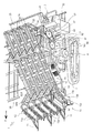
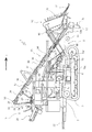
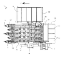
図1から図5において、鱗茎野菜をニンニクとしたニンニク収穫機1の全体構成から説明する。ニンニク収穫機1は畝上に植えられた複数条のニンニクを収穫するものである。本実施形態では4条に植えられたニンニク10を収穫するニンニク収穫機1について説明する。なお、F方向を前方と規定して説明する。   In FIG. 1 to FIG. 5, the overall configuration of a garlic harvester 1 using garlic as a bulb vegetable will be described. The garlic harvesting machine 1 is for harvesting a plurality of garlics planted on a cocoon. In this embodiment, a garlic harvesting machine 1 that harvests garlic 10 planted in four rows will be described. In the following description, the F direction is defined as the front.

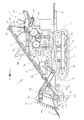
ニンニク収穫機1は、左右のクローラ2・2を備えるクローラ式走行装置上に機体フレーム3を設けてシャーシとし、左右のクローラ2・2は畝を跨いで走行し、植付条の両側の畝間に左右のクローラ2・2が位置するようにして走行しながら収穫する。但し、左右のクローラ2・2の間隔を狭めて、平畝上を走行するようにし、植付条を踏みつけて走行する構成とすることもできる。   The garlic harvesting machine 1 is provided with a body frame 3 on a crawler type traveling device having left and right crawlers 2 and 2 as a chassis, and the left and right crawlers 2 and 2 run across the ridges, and between the ridges on both sides of the planting strip Harvest while traveling so that the left and right crawlers 2 and 2 are positioned at the right. However, the distance between the left and right crawlers 2 and 2 can be narrowed so that the vehicle travels on a flat surface, and the vehicle travels by stepping on the planting strip.

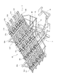
前記機体フレーム3上に上部フレーム8を上下回動可能に支持している。図1、図6に示すように、機体フレーム3の前後中途部の左右両側には支柱3a・3aが立設され、支柱3a・3aの上部に昇降中心軸80が横架され、該昇降中心軸80に上部フレーム8の後下部が上下回動自在に支持される。上部フレーム8は下支持フレーム81とその上側に取り付ける搬送フレーム82からなり、下支持フレーム81は後述するデバイダ11や押えローラ14や土落とし装置16や肩揃え装置17や根切断装置18等を取り付ける。搬送フレーム82は引き起こし装置12や引抜搬送装置15を取り付ける。   An upper frame 8 is supported on the body frame 3 so as to be rotatable up and down. As shown in FIG. 1 and FIG. 6, support columns 3a and 3a are erected on both the left and right sides of the front and rear halfway part of the body frame 3, and an elevating center shaft 80 is horizontally mounted on the upper portions of the support columns 3a and 3a. A rear portion of the upper frame 8 is supported on the shaft 80 so as to be rotatable up and down. The upper frame 8 includes a lower support frame 81 and a conveyance frame 82 attached to the upper side thereof. The lower support frame 81 is attached with a divider 11, a presser roller 14, a soil removing device 16, a shoulder aligning device 17, a root cutting device 18, and the like which will be described later. . The conveying frame 82 is attached to the raising device 12 and the drawing conveying device 15.

下支持フレーム81の下部と機体フレーム3との間には電動油圧シリンダ6が介装され(図3、図4)、上部フレーム8を昇降中心軸80を中心に昇降可能としている。電動油圧シリンダ6を伸縮させることで引き起こし装置12や掘り起し装置13や引抜搬送装置15の高さを変更可能としている。また、昇降駆動装置を電動油圧シリンダ6とすることで、伸縮長を電気的に容易に制御できるようにしている。
機体フレーム3の左側部上にエンジン4が載置され、機体フレーム3の左後部に操縦支持フレーム3bが立設され、操縦支持フレーム3b上に主クラッチレバーや操向レバー等を備える操縦部5が配置される。つまり、操縦部5の前方にエンジン4が配置される。エンジン4からの動力は左右のクローラ2・2の間に配置したミッションケース7や後述する引き起こし装置12や引抜搬送装置15や根切断装置18や茎葉切断装置20等に動力を伝達して駆動できるようにしている。
An electro-hydraulic cylinder 6 is interposed between the lower portion of the lower support frame 81 and the body frame 3 (FIGS. 3 and 4), and the upper frame 8 can be moved up and down around a lifting center shaft 80. The height of the device 12, the digging device 13, and the drawing and conveying device 15 can be changed by extending and contracting the electric hydraulic cylinder 6. Further, by using the electric hydraulic cylinder 6 as the elevating drive device, the expansion / contraction length can be easily controlled electrically.
The engine 4 is placed on the left side of the body frame 3, the steering support frame 3b is erected on the left rear part of the body frame 3, and the control unit 5 includes a main clutch lever, a steering lever, and the like on the steering support frame 3b. Is placed. That is, the engine 4 is disposed in front of the control unit 5. The power from the engine 4 can be driven by transmitting the power to the mission case 7 disposed between the left and right crawlers 2, the trigger device 12, the pulling / conveying device 15, the root cutting device 18, and the foliage cutting device 20, which will be described later. I am doing so.

前記搬送フレーム82は、引抜搬送装置15を支持するものであり、図6に示すように、搬送手段となる搬送ベルト27を支持する駆動プーリ24と従動プーリ25とガイドプーリ26を取り付ける取付フレーム82aと、取付フレーム82aを支持する支持フレーム82bと、取付フレーム82aと支持フレーム82bを連結する連結ステー82cと、支持フレーム82b・82b・・・を連結する補強フレーム82dと連結パイプ82eからなる。   The conveying frame 82 supports the drawing / conveying device 15, and as shown in FIG. 6, a mounting frame 82a for attaching the driving pulley 24, the driven pulley 25, and the guide pulley 26 that supports the conveying belt 27 serving as conveying means. , A support frame 82b for supporting the mounting frame 82a, a connecting stay 82c for connecting the mounting frame 82a and the supporting frame 82b, a reinforcing frame 82d for connecting the supporting frames 82b, 82b,.

前記取付フレーム82aは1条に対して左右一対備え、4条収穫するため4対有し、前後方向に配置される。支持フレーム82bは植付条の両側、つまり、左右一対の取付フレーム82a・82aの両側に前後方向に配置される。取付フレーム82aと支持フレーム82bは左右平行に配置され、連結ステー82c・82c・・・が前後適宜間隔をあけて左右方向に配置されて取付フレーム82aと支持フレーム82bを連結固定している。支持フレーム82bは前記下支持フレーム81の上部に固定される。前記補強フレーム82dは側面視三角形状に構成されて支持フレーム82b上に前後一対立設され、左右の各支持フレーム82b・82b・・・上の補強フレーム82d・82d・・・同士は連結パイプ82eで連結されている。つまり、左右に配置した複数の補強フレーム82d・82d・・・は連結パイプ82eで連結され、前後一対配置される。   The mounting frame 82a is provided with a pair of left and right with respect to one strip, and has four pairs for harvesting four strips, and is arranged in the front-rear direction. The support frame 82b is disposed in the front-rear direction on both sides of the planting strip, that is, on both sides of the pair of left and right mounting frames 82a and 82a. The mounting frame 82a and the support frame 82b are arranged in parallel in the left-right direction, and connecting stays 82c, 82c,... Are arranged in the left-right direction with an appropriate interval in the front-rear direction to connect and fix the mounting frame 82a and the support frame 82b. The support frame 82b is fixed to the upper part of the lower support frame 81. The reinforcing frame 82d has a triangular shape when viewed from the side, and is arranged on the support frame 82b so as to face each other. The reinforcement frames 82d, 82d on the left and right support frames 82b, 82b,. It is connected with. That is, the plurality of reinforcing frames 82d, 82d,... Arranged on the left and right are connected by the connecting pipe 82e, and a pair of front and rear are arranged.

前記搬送フレーム82の支持フレーム82bの前端にはデバイダ11が設けられ、該デバイダ11の後部に引き起こし装置12が配置される。デバイダ11は植付条と植付条の間を通過させて絡まったり寝たりしたニンニク10の茎葉部10bを分草するものである。引き起こし装置12は分草後の茎葉部10bを引き上げるもので、タインを縦回しにして分草した茎を上方に持ち上げるようにしている。引き起こし装置12は植付条の両側に配置されるため、5つ平行に配置される。引き起こし装置12の引き起こしケース12aは下部が支持フレーム82bの前端に固定され、上後部が前記連結パイプ82eに固定される。   A divider 11 is provided at the front end of the support frame 82 b of the transport frame 82, and a raising device 12 is disposed at the rear of the divider 11. The divider 11 weeds the foliage portion 10b of the garlic 10 that has been entangled or slept by passing between the planting strips. The raising device 12 pulls up the foliage portion 10b after weeding, and the tine is rotated vertically to lift the weeded stem. Since the raising devices 12 are arranged on both sides of the planting strip, five are arranged in parallel. The lower part of the raising case 12a of the raising device 12 is fixed to the front end of the support frame 82b, and the upper rear part is fixed to the connecting pipe 82e.

引き起こし装置12の後下方には掘り起し装置13が配置される。掘り起し装置13は正面視略U字状の掘り起し刃13aと掘り起し刃13aを揺動自在に支持する支持体13bと駆動部13c等からなる。支持体13bは搬送フレーム82前部の左右両側に配置され、掘り起し刃13aの左右両側上部を前後揺動自在に支持する。なお、掘り起し刃13aの上部はピンにより前後揺動自在に支持され、掘り起し刃13aの側面には支持孔が上下方向に所定間隔をあけて複数設けられ、ピンの取付位置を変更することで掘り起し深さを調節可能としている。掘り起し刃13aは本実施形態では4条分掘り起こせる幅としている。掘り起し刃13aの上部には駆動部13cが連結され、前後揺動駆動可能としている。そして、掘り起し刃13aを畝の土内に差し込んでニンニク10の球部10aよりも下方に位置させ、掘り起し刃13aを前後揺動させながら前進することで、畝を崩して土壌を柔らかくし、ニンニク10を容易に引き抜けるようにしている。   A digging and raising device 13 is disposed below the raising device 12. The digging device 13 includes a digging and raising blade 13a having a substantially U shape when viewed from the front, a support 13b that swingably supports the digging and raising blade 13a, a drive unit 13c, and the like. The support 13b is disposed on both the left and right sides of the front portion of the conveyance frame 82, and supports the upper portions of the left and right sides of the digging blade 13a so as to be swingable back and forth. The upper part of the digging blade 13a is supported by a pin so as to be swingable back and forth, and a plurality of support holes are provided on the side surface of the digging blade 13a at predetermined intervals in the vertical direction to change the mounting position of the pin. By doing so, the depth of digging can be adjusted. In this embodiment, the digging and raising blade 13a has a width capable of digging up four lines. A driving portion 13c is connected to the upper portion of the digging blade 13a so that it can be driven back and forth. Then, the digging blade 13a is inserted into the soil of the reed and positioned below the ball portion 10a of the garlic 10, and the digging and retreating blade 13a is moved forward and backward to break up the reed and destroy the soil. It is made soft so that the garlic 10 can be pulled out easily.

掘り起し装置13の後上部で引抜搬送装置15の前下方には押えローラ14が配置されている。押えローラ14はニンニク10の植付条の両側に配置され、本実施形態では5個配置される。押えローラ14はアームの一端(下端)に回動自在に支持され、アームの他端(上端)は搬送フレーム8の前下部に回動自在に支持され、アームは下方へ回動するようにバネ等で付勢されている。こうして、引抜搬送装置15によりニンニク10を引き抜き上げるときに、押えローラ14により畝を覆うマルチフィルムを下方に押さえ付けて、マルチフィルムが一緒に持ち上げられないようにしている。このような構成とすることによって、マルチフィルムの両側から掘り起し刃13aを畝内に挿入し、マルチフィルムを切り裂くことなく押え付けてニンニク10のみ持ち上げられて引き抜かれて、後上方へ搬送されるのである。   A pressing roller 14 is disposed at the upper rear portion of the digging and raising device 13 and at the front lower side of the drawing and conveying device 15. The presser rollers 14 are arranged on both sides of the garlic 10 planting strip, and in this embodiment, five presser rollers 14 are arranged. The presser roller 14 is rotatably supported at one end (lower end) of the arm, the other end (upper end) of the arm is rotatably supported at the front lower portion of the conveyance frame 8, and the arm is spring-loaded so as to rotate downward. Etc. are energized. Thus, when the garlic 10 is pulled up by the pulling and conveying device 15, the multi-film covering the ridge is pressed downward by the presser roller 14 so that the multi-film cannot be lifted together. By adopting such a configuration, the multi-film is dug up from both sides, the blades 13a are inserted into the cage, the multi-film is pressed without tearing, and only the garlic 10 is lifted and pulled out, and conveyed rearward and upward. It is.

引抜搬送装置15は、前低後高に傾斜して設けられ、ニンニク10の茎葉部10bを挟持して上後方へ搬送しながらニンニク10を抜き上げて、後方へ搬送するものである。引抜搬送装置15は搬送フレーム82上に取り付けられる。搬送手段となる駆動プーリ24・24・・・と従動プーリ25・25・・・とガイドプーリ26・26・・・は前記取付フレーム82a・82a・・・の下側に取り付けられる。搬送手段は4条分4組配置され、1組は左右対称に配置されるため、一つの取付フレーム82aに取り付けられる引抜搬送装置15について説明する。   The drawing / conveying device 15 is provided so as to be inclined at the front, lower, and rear heights. The garlic 10 is picked up and conveyed backward while nipping the foliage portion 10b of the garlic 10 and conveying it upward and backward. The drawing / conveying device 15 is mounted on a conveying frame 82. The drive pulleys 24, 24,..., The driven pulleys 25, 25,... And the guide pulleys 26, 26, which serve as conveying means, are attached to the lower side of the mounting frames 82a, 82a,. Since the conveying means is arranged in four sets for four strips and one set is arranged symmetrically, the pulling and conveying apparatus 15 attached to one attachment frame 82a will be described.

前記取付フレーム82aの後端には駆動プーリ24を固定する搬送駆動軸56が下方に突出して回転自在支持される。取付フレーム82aの前端には従動プーリ25を回転自在に支持する従動軸57(図4)が下方に突出して固定される。駆動プーリ24と従動プーリ25との間には適宜間隔をあけて複数のガイドプーリ26・26・・・が回転自在に支持されるガイドプーリ軸58・58・・・が下方に突出して固定される。駆動プーリ24と従動プーリ25とガイドプーリ26に搬送ベルト27が巻回される。こうして、左右の搬送ベルト27・27の間にニンニク10の茎葉部10bが挟持されて、引抜搬送装置15の前部でニンニク10を引き抜いて、後方へ搬送する。そして、駆動プーリ24と従動プーリ25とガイドプーリ26を支持する軸(搬送駆動軸56、従動軸57、ガイドプーリ軸58)が取付フレーム82aから下方へ突出して設けるため、搬送ベルト27を後述する肩揃え装置17にできるだけ近づけて配置でき、できるだけニンニク10の肩近くから茎葉部10bを上方へ引っ張り姿勢を整えることができ、ガイドプーリ26が邪魔にならないようにしている。   A conveying drive shaft 56 that fixes the drive pulley 24 protrudes downward and is rotatably supported at the rear end of the mounting frame 82a. A driven shaft 57 (FIG. 4) that rotatably supports the driven pulley 25 is fixed to the front end of the mounting frame 82a so as to protrude downward. A plurality of guide pulleys 26, 26,... Are rotatably supported between the drive pulley 24 and the driven pulley 25 at appropriate intervals. The A conveyor belt 27 is wound around the drive pulley 24, the driven pulley 25, and the guide pulley 26. Thus, the foliage portion 10b of the garlic 10 is sandwiched between the left and right transport belts 27, 27, and the garlic 10 is pulled out at the front portion of the pulling and transporting device 15 and transported backward. Since the driving pulley 24, the driven pulley 25, and the shaft for supporting the guide pulley 26 (the conveying driving shaft 56, the driven shaft 57, and the guide pulley shaft 58) are provided so as to protrude downward from the mounting frame 82a, the conveying belt 27 will be described later. It can be arranged as close as possible to the shoulder aligner 17, and the foliage portion 10 b can be pulled upward from as close as possible to the shoulder of the garlic 10 so that the guide pulley 26 does not get in the way.

図1、図3、図7に示すように、前記押えローラ14よりも後方で引抜搬送装置15の前下方には土落とし装置16が配置される。土落とし装置16は下支持フレーム81に回転自在に支持した回転軸16aと、棒状体を放射状に突設した弾性体16b・16b・・・とにより構成される。弾性体16bは本実施形態では120度間隔をあけて棒状体を3本突設した構造としているが限定するものではなく、4本以上設けてもよく、また、ブラシ等で構成することも可能である。さらに、回転軸16aの一端には駆動プーリ16cが固設され、ベルト駆動可能としている。そして、土落とし装置16は、本実施形態では前後2組配置され、互いに反対方向に回転するように駆動される。こうして、回転軸16aを回転させることで、搬送されるニンニク10の根部に弾性体16bを下方から当接されて、ニンニク10を傷つけることなく、根に付着した土を搬送時に落とすことができるのである。そして、前後の土落とし装置16・16により前方向からと後方向から弾性体16bを当接させるので、根に絡みついた土をきれいに落とすことができるのである。   As shown in FIGS. 1, 3, and 7, a soil dropping device 16 is disposed behind the pressing roller 14 and in front of and below the pulling and conveying device 15. The earth dropping device 16 includes a rotating shaft 16a rotatably supported on the lower support frame 81, and elastic bodies 16b, 16b,. In the present embodiment, the elastic body 16b has a structure in which three rod-shaped bodies project at intervals of 120 degrees. However, the elastic body 16b is not limited, and four or more elastic bodies 16b may be provided, or may be configured by a brush or the like. It is. Further, a driving pulley 16c is fixed to one end of the rotating shaft 16a so that the belt can be driven. In the present embodiment, two sets of front and rear soil removal devices 16 are arranged and are driven to rotate in opposite directions. Thus, by rotating the rotating shaft 16a, the elastic body 16b is brought into contact with the root portion of the garlic 10 being conveyed from below, so that the soil adhering to the root can be dropped during transportation without damaging the garlic 10. is there. And since the elastic body 16b is contact | abutted from the front direction and the back direction by the front and back soil dropping apparatus 16 * 16, the soil entangled in the root can be dropped neatly.

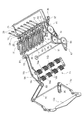
前記引抜搬送装置15の後部下方には4組の肩揃え装置17が前後略水平方向に配設され、下支持フレーム81に支持される。各組の肩揃え装置17は同じ構成であるため、1条の肩揃え装置17について説明する。図7、図8、図9に示すように、肩揃え装置17は左右一対のベルト47・47が肩揃え駆動プーリ43と従動プーリ46の間に巻回され、左右一対のベルト47・47の間を前記引抜搬送装置15と同期させて駆動することにより、ニンニク10の茎葉部10bが引抜搬送装置15により引き上げられ、ニンニク10の球部10aと茎葉部10bの境界部分を肩部として、その肩部が肩揃え装置17のベルト47・47で止められて肩部が揃えられるのである。   Four sets of shoulder aligning devices 17 are arranged in a substantially horizontal direction in the front-rear direction below the rear portion of the drawing / conveying device 15 and supported by the lower support frame 81. Since each set of shoulder alignment devices 17 has the same configuration, only one shoulder alignment device 17 will be described. As shown in FIGS. 7, 8, and 9, the shoulder aligner 17 has a pair of left and right belts 47, 47 wound around a shoulder alignment drive pulley 43 and a driven pulley 46. By driving in synchronization with the pulling and conveying device 15, the foliage portion 10b of the garlic 10 is pulled up by the pulling and conveying device 15, and the boundary portion between the ball portion 10a and the foliage portion 10b of the garlic 10 is used as a shoulder. The shoulder portion is stopped by the belts 47 and 47 of the shoulder aligning device 17 so that the shoulder portion is aligned.

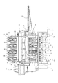
肩揃え装置17の前後中途部の下方には根切断装置18が配置される。根切断装置18はバリカン式往復刃が左右方向に配置される。根切断装置18は4条分のニンニク10の根を一度に切断できるように左右方向の長さを引抜搬送装置15の左右幅に合わせた長さとしている。この根切断装置18の構成は後述する。   A root cutting device 18 is disposed below the midway portion of the shoulder alignment device 17. The root cutting device 18 has a clipper reciprocating blade arranged in the left-right direction. The root cutting device 18 has a length in the left-right direction that matches the left-right width of the drawing / conveying device 15 so that the roots of the garlic 10 for four strips can be cut at a time. The configuration of the root cutting device 18 will be described later.

前記肩揃え装置17の後部上には整茎装置19が配置され、更に整茎装置19の後部上に茎葉切断装置20が配置される。整茎装置19は星型に形成された左右一対の保持板19a・19aからなり、保持板19a・19aはゴム等の弾性体板で構成され、左右の保持板19a・19aは互いに当接して回転自在に支持されている。保持板19a・19aの上下方向の高さ(厚さ)はニンニクの茎を残すための長さに一致させている。
茎葉切断装置20は左右一対の円板状の切断刃52・52からなり、整茎装置19の後部上に配置される。茎葉切断装置20の切断刃52・52は水平に配置されて保持板19a・19aの上面に近接して配置される。
こうして、肩揃え装置17を通過したニンニク10は、球部10aから上方の茎葉部10bが整茎装置19により略上下方向を向くように保持されながら後方へ搬送されて、茎葉部10bが略同じ長さで残るように茎葉切断装置20により切断される。なお、茎葉切断装置20により切断された後に球部10aに残す茎葉部10bの長さは、ベルト47の下端から茎葉切断装置20の切断刃52までの距離により決まり、肩揃え駆動軸42上に固定される後述する切断刃駆動スプロケット44の上下に外嵌されるカラーを交換することにより数段階に変更可能としている。但し、この変更構成は限定するものではなく、肩揃え駆動軸42に複数のピン孔を開口して、ピンの差し替えにより変更することもできる。
A stalking device 19 is disposed on the rear part of the shoulder aligning device 17, and a foliage cutting device 20 is disposed on the rear part of the stalking device 19. The stalking device 19 is composed of a pair of left and right holding plates 19a and 19a formed in a star shape. The holding plates 19a and 19a are made of an elastic plate such as rubber, and the left and right holding plates 19a and 19a are in contact with each other. It is supported rotatably. The height (thickness) of the holding plates 19a and 19a in the vertical direction is matched with the length for leaving the garlic stem.
The foliage cutting device 20 includes a pair of left and right disc-shaped cutting blades 52 and 52, and is disposed on the rear portion of the stalking device 19. The cutting blades 52 and 52 of the foliage cutting device 20 are horizontally disposed and are disposed close to the upper surfaces of the holding plates 19a and 19a.
In this way, the garlic 10 that has passed through the shoulder aligning device 17 is conveyed backward while the upper stem and leaf portion 10b of the ball portion 10a is held in the substantially vertical direction by the stem adjusting device 19, and the stem and leaf portion 10b is substantially the same. It is cut by the foliage cutting device 20 so as to remain in the length. Note that the length of the foliage portion 10b remaining on the ball portion 10a after being cut by the foliage cutting device 20 is determined by the distance from the lower end of the belt 47 to the cutting blade 52 of the foliage cutting device 20, and is on the shoulder alignment drive shaft 42. It can be changed in several stages by exchanging the collars fitted on the upper and lower sides of a fixed cutting blade drive sprocket 44 to be described later. However, this change configuration is not limited, and a plurality of pin holes can be opened in the shoulder alignment drive shaft 42 and changed by replacing the pins.

また更に、前記肩揃え装置17の後上方、引抜搬送装置15の後部下方には、補助茎葉搬送装置110を設けて、切断後の茎葉部10bを確実に挟持して、後述する排葉コンベア23へ搬送するように構成することも可能である。補助茎葉搬送装置110は図12、図13に示すように、茎葉切断装置20の前上方(根切断装置18の上方)から肩揃え装置17の後上方で排葉コンベア23の上方まで、肩揃え装置17と平行で搬送経路を合わせて配置される。補助茎葉搬送装置110は4条に対応して4組配置されるため、1条の補助茎葉搬送装置110に付いて説明する。   Furthermore, an auxiliary foliage conveying device 110 is provided at the rear upper side of the shoulder aligning device 17 and the rear lower portion of the drawing conveying device 15 so as to securely clamp the cut foliage portion 10b, which will be described later. It can also be configured to be conveyed to. As shown in FIGS. 12 and 13, the auxiliary foliage transport device 110 is shoulder aligned from the front upper side of the foliage cutting device 20 (above the root cutting device 18) to the upper rear side of the shoulder aligning device 17 and above the leaf discharging conveyor 23. It is arranged in parallel with the apparatus 17 so as to match the conveyance path. Since four sets of auxiliary foliage conveying devices 110 are arranged corresponding to the four lines, only one auxiliary foliage conveying apparatus 110 will be described.

補助茎葉搬送装置110は、左右一対の補助茎葉搬送フレーム111・111の後部に設けられる左右一対の駆動プーリ112・112と、左右一対の補助茎葉搬送フレーム111・111の前部に設けられる左右一対の従動プーリ113・113と、左右一対の駆動プーリ112・112と左右一対の従動プーリ113・13との間に巻回される左右一対の挟持ベルト114・114と、前記肩揃え駆動軸42・42上に固定される伝動プーリ115・115と、伝動プーリ115・115と駆動プーリ112・112との間に巻回される伝動ベルト116・116等からなる。   The auxiliary foliage conveyance device 110 includes a pair of left and right drive pulleys 112 and 112 provided at the rear of the pair of left and right auxiliary foliage conveyance frames 111 and 111, and a pair of left and right provided at the front of the pair of left and right auxiliary foliage conveyance frames 111 and 111. Driven pulleys 113 and 113, a pair of left and right drive pulleys 112 and 112, and a pair of left and right driven pulleys 113 and 13, and a pair of left and right clamping belts 114 and 114, and the shoulder alignment drive shaft 42 and Transmission pulleys 115 and 115 fixed on the belt 42, transmission belts 116 and 116 wound between the transmission pulleys 115 and 115 and the drive pulleys 112 and 112, and the like.

前記駆動プーリ112は二連プーリで構成され、挟持ベルト114と伝動ベルト116を巻回できるようにしている。伝動プーリ115は駆動プーリ112と従動プーリ113の間に配置され、補助茎葉搬送装置110の後部は肩揃え装置17の後部よりも後方に延設される。前記補助茎葉搬送フレーム111・111の後部下面から下方に取付フレーム117・117が垂設され、該取付フレーム117・117の下端は前記搬送伝動ケース40に固定される。こうして、補助茎葉搬送装置110は搬送伝動ケース40に支持される。   The drive pulley 112 is constituted by a double pulley, and can wind the pinching belt 114 and the transmission belt 116. The transmission pulley 115 is disposed between the drive pulley 112 and the driven pulley 113, and the rear portion of the auxiliary foliage transport device 110 extends rearward from the rear portion of the shoulder aligner 17. Mounting frames 117 and 117 are provided below the lower surfaces of the rear portions of the auxiliary foliage transport frames 111 and 111, and lower ends of the mounting frames 117 and 117 are fixed to the transport transmission case 40. Thus, the auxiliary foliage transport device 110 is supported by the transport transmission case 40.

このような構成において、肩揃え駆動軸42に伝達された動力が、伝動プーリ115、伝動ベルト116を介して駆動プーリ112に伝えられ、該駆動プーリ112から挟持ベルト114を回転駆動できるようにしている。こうして、左右の挟持ベルト114・114が互いに逆方向に回転され、引抜搬送装置15及び肩揃え装置17と同期して回転されることで、引抜搬送装置15により搬送されてきたニンニク10は、その茎葉部10bが肩揃え装置17と補助茎葉搬送装置110により挟持されて、後方へ搬送され、肩を揃えられた後、根部が切断され、球部10aの上部の茎葉部10bが整茎装置19により整えられて切断されるときに、引抜搬送装置15よりも低い位置の補助茎葉搬送装置110と肩揃え装置17との上下で挟持されているので、茎葉部10bが抜けることなく確実に安定して搬送されながら切断することができる。そして、排葉コンベア23にも確実に載せることができる。   In such a configuration, the power transmitted to the shoulder alignment drive shaft 42 is transmitted to the drive pulley 112 via the transmission pulley 115 and the transmission belt 116 so that the pinching belt 114 can be rotationally driven from the drive pulley 112. Yes. Thus, the left and right clamping belts 114 and 114 are rotated in opposite directions and rotated in synchronization with the pulling and conveying device 15 and the shoulder aligning device 17, so that the garlic 10 conveyed by the pulling and conveying device 15 is The foliage portion 10b is sandwiched between the shoulder alignment device 17 and the auxiliary foliage conveyance device 110 and conveyed rearward, after the shoulders are aligned, the root portion is cut, and the foliage portion 10b at the upper part of the ball portion 10a is replaced by the styling device 19. Since the auxiliary foliage conveying device 110 and the shoulder aligning device 17 at a lower position than the pulling and conveying device 15 are sandwiched between the upper and lower sides when being arranged and cut by the above, the foliage portion 10b is surely stabilized without coming off. Can be cut while being conveyed. Then, it can be reliably placed on the leaf conveyor 23.

前記肩揃え装置17の後端下方に、受止め解放可能に受樋21が配置され(図4)、その下方にコンテナ台22が配置される。コンテナ台22上に4条分のコンテナ9・9・・・を左右に載置して、前記肩揃え装置17の後端から落下するニンニク10を収納できるようにしている。受樋21は通常解放状態として、コンテナ9が満杯となると、受樋21を受止め位置とし、前記肩揃え装置17から落下するニンニク10を一時受け止め、コンテナ9を交換する間受樋21で受けておく、交換後は解放して交換したコンテナ9にニンニク10を収納できるようにしている。   Under the rear end of the shoulder aligning device 17, a receiving rod 21 is disposed so as to be receivable and releasable (FIG. 4), and a container base 22 is disposed below the receiving rod 21. .. Are placed left and right on the container base 22 so that the garlic 10 falling from the rear end of the shoulder aligner 17 can be stored. The receptacle 21 is in a normally released state, and when the container 9 is full, the receptacle 21 is placed in the acceptance position, the garlic 10 falling from the shoulder aligning device 17 is temporarily received, and the receptacle 9 is received while the container 9 is replaced. In addition, after the replacement, the garlic 10 can be stored in the container 9 that is released and replaced.

また、前記肩揃え装置17の上後方であって引抜搬送装置15の後端下方には切断後の葉を側方へ排出する排葉コンベア23が配置される。排葉コンベア23はベルトコンベアからなり、左右方向で操縦部5と反対側の右側に排出するように構成している。
そして、引抜搬送装置15の右側方に空のコンテナを載置しておく予備コンテナ台30が上方へ折り畳み収納可能に配置されている。
Further, a leaf discharge conveyor 23 for discharging the cut leaves to the side is disposed above and behind the shoulder aligning device 17 and below the rear end of the pulling and conveying device 15. The leaf conveyor 23 comprises a belt conveyor, and is configured to discharge to the right side opposite to the control unit 5 in the left-right direction.
A spare container base 30 on which an empty container is placed on the right side of the drawing / conveying device 15 is disposed so as to be folded upward and stored.

次に、駆動構成について、図1、図2、図3、図7より説明する。
前記エンジン4の出力軸には出力プーリ87が固設され、該出力プーリ87からベルトを介してその後方に配置された走行駆動プーリ90に動力が伝達される。走行駆動プーリ90は走行駆動軸91に固設され、該走行駆動軸91からプーリやベルト等を介してミッションケース7に動力が伝達されるようにしている。
Next, the drive configuration will be described with reference to FIGS. 1, 2, 3, and 7. FIG.
An output pulley 87 is fixed to the output shaft of the engine 4, and power is transmitted from the output pulley 87 to a travel drive pulley 90 disposed behind the belt via a belt. The travel drive pulley 90 is fixed to the travel drive shaft 91 so that power is transmitted from the travel drive shaft 91 to the transmission case 7 via a pulley, a belt, or the like.

また、前記走行駆動軸91上には伝動プーリが固設され、ベルトを介してその上方に設けた作業駆動プーリ92に動力が伝達される。作業駆動プーリ92は前記昇降中心軸80上に固設され、該昇降中心軸80の右側に伝動プーリ93とアーム89が固設され、該アーム89の回動によるクランク運動を根切断装置18に伝えて往復刃を駆動する。前記伝動プーリ93からはベルト94を介して前記土落とし装置16の駆動プーリ16c・16cと伝動プーリ88に動力を伝達して土落とし装置16を駆動する。更に、伝動プーリ88からベルト・プーリを介して掘り起し駆動軸95に動力を伝達し掘り起し装置13を駆動する。掘り起し駆動軸95の左側端に固設したプーリよりベルトを介して引き起こし装置12の引き起こし駆動軸96に動力を伝達して引き起こし装置12を駆動する。   Further, a transmission pulley is fixed on the travel drive shaft 91, and power is transmitted to a work drive pulley 92 provided above the belt via a belt. The work drive pulley 92 is fixed on the elevating central shaft 80, and a transmission pulley 93 and an arm 89 are fixed on the right side of the elevating central shaft 80, and the crank motion caused by the rotation of the arm 89 is transmitted to the root cutting device 18. Informs and drives the reciprocating blade. Power is transmitted from the transmission pulley 93 to the drive pulleys 16c and 16c and the transmission pulley 88 of the soil removal device 16 via the belt 94 to drive the soil removal device 16. Further, the transmission pulley 88 is dug up through the belt pulley to transmit power to the drive shaft 95 to drive the dug up device 13. The apparatus 12 is driven by excavating and driving the belt 12 through a belt from a pulley fixed to the left end of the drive shaft 95 and transmitting the power to the drive shaft 96 of the apparatus 12.

また、前記昇降中心軸80の左側に伝動プーリが固設され、該伝動プーリよりベルト、プーリを介して搬送伝動ケース40の入力軸41に動力が伝達される。搬送伝動ケース40は前記下支持フレーム81の後部上に左右方向に横設され、図7、図8、図9に示すように、搬送伝動ケース40の上面から肩揃え駆動軸42・42・・・が上方に突出されている。肩揃え駆動軸42には肩揃え駆動プーリ43と切断刃駆動スプロケット44が固設され、肩揃え駆動プーリ43からベルト47を介して肩揃え装置17と整茎装置19を駆動し、切断刃駆動スプロケット44よりチェーンを介して茎葉切断装置20を駆動する。   A transmission pulley is fixed to the left side of the elevating central shaft 80, and power is transmitted from the transmission pulley to the input shaft 41 of the transport transmission case 40 through the belt and the pulley. The conveyance transmission case 40 is laterally arranged on the rear part of the lower support frame 81 in the left-right direction. As shown in FIGS. 7, 8, and 9, the shoulder alignment drive shafts 42, 42,. -Protrudes upward. A shoulder alignment drive pulley 43 and a cutting blade drive sprocket 44 are fixed to the shoulder alignment drive shaft 42, and the shoulder alignment device 17 and the stalking device 19 are driven from the shoulder alignment drive pulley 43 via the belt 47 to drive the cutting blade. The foliage cutting device 20 is driven from the sprocket 44 through the chain.

更に、前記肩揃え駆動軸42の上端よりユニバーサルジョイント54、伝動軸55、ユニバーサルジョイント59を介して搬送駆動軸56に動力を伝達し、引抜搬送装置15を駆動する。
また、前記搬送伝動ケース40の入力軸41上には伝動プーリ97が固設され、該伝動プーリ97よりベルト、プーリを介して排葉コンベア23の入力軸98に動力が伝達され、排葉コンベア23を駆動するようにしている。
Further, power is transmitted from the upper end of the shoulder alignment drive shaft 42 to the transport drive shaft 56 via the universal joint 54, the transmission shaft 55, and the universal joint 59 to drive the pulling and transporting device 15.
A transmission pulley 97 is fixed on the input shaft 41 of the transport transmission case 40, and power is transmitted from the transmission pulley 97 to the input shaft 98 of the leaf conveyor 23 via the belt and pulley. 23 is driven.

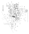
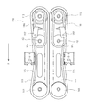
前記根切断装置18は、図8、図10、図11に示すように、駆動手段70と、切断刃71(受刃71aと摺動刃71b)と、切断刃フレーム73と、揺動軸74と、弾性部材となるバネ75とからなる。   As shown in FIGS. 8, 10, and 11, the root cutting device 18 includes a driving means 70, a cutting blade 71 (a receiving blade 71 a and a sliding blade 71 b), a cutting blade frame 73, and a swing shaft 74. And a spring 75 serving as an elastic member.

切断刃フレーム73は、切断刃71(受刃71aと摺動刃71b)を支持するものであり、切断刃フレーム73の左右両側に配置される前後方向の側板からは左右水平方向に揺動軸74・74が外側方に突出される。該揺動軸74・74は前記下支持フレーム81に揺動自在に支持される。前記切断刃フレーム73の左右一側(本実施形態では左側)の側板から係止ピン76が突設され、該係止ピン76にバネ75の下端が係止され、バネ75の上端は前記下支持フレーム81に係止されている。こうして、根切断装置18の前部が上方へ回動するようにバネ75により付勢されている。また、前記切断刃フレーム73の側板の前部から側方にストッパ77が突設されて前記下支持フレーム81に当接可能に配置され、切断刃71の上昇位置が設定されている。   The cutting blade frame 73 supports the cutting blade 71 (the receiving blade 71a and the sliding blade 71b), and swings in the horizontal direction from the front and rear side plates disposed on the left and right sides of the cutting blade frame 73. 74 and 74 are projected outward. The swing shafts 74 are supported by the lower support frame 81 so as to be swingable. A locking pin 76 projects from a side plate on one of the left and right sides (left side in the present embodiment) of the cutting blade frame 73, and the lower end of the spring 75 is locked to the locking pin 76. Locked to the support frame 81. In this way, the front portion of the root cutting device 18 is biased by the spring 75 so as to rotate upward. Further, a stopper 77 protrudes laterally from the front part of the side plate of the cutting blade frame 73 and is disposed so as to be able to contact the lower support frame 81, and the rising position of the cutting blade 71 is set.

前記切断刃フレーム73には、切断刃71を構成する鋸刃状の受刃71aが左右方向に固定され、該受刃71aに鋸刃状の摺動刃71bが左右摺動自在に嵌合される。該摺動刃71bの一側(本実施形態では右側)上にはブラケット63が固定され、該ブラケット63に駆動手段70が連結される。駆動手段70は、前記ブラケット63にベルクランクアーム64の一端が枢結され、該ベルクランクアーム64の中途部が切断刃フレーム73に回転自在に支持され、ベルクランクアーム64の他端がL字状のステー65を介して揺動アーム66の上部に揺動自在に連結される。揺動アーム66は上下中途部が切断刃フレーム73の側板から突設した揺動支持軸67に揺動自在に支持される。前記揺動アーム66の下部が連結ロッド68の後部に枢支され、連結ロッド68の前部が前記アーム89に枢結される。   A saw blade-shaped receiving blade 71a constituting the cutting blade 71 is fixed to the cutting blade frame 73 in the left-right direction, and a saw blade-shaped sliding blade 71b is slidably fitted to the receiving blade 71a. The A bracket 63 is fixed on one side (right side in the present embodiment) of the sliding blade 71b, and the driving means 70 is connected to the bracket 63. In the driving means 70, one end of a bell crank arm 64 is pivotally connected to the bracket 63, a middle portion of the bell crank arm 64 is rotatably supported by a cutting blade frame 73, and the other end of the bell crank arm 64 is L-shaped. It is connected to the upper part of the swing arm 66 through a stay 65 in a swingable manner. The swing arm 66 is supported in a swingable manner by a swing support shaft 67 projecting from the side plate of the cutting blade frame 73 in the middle of the upper and lower sides. The lower part of the swing arm 66 is pivotally supported by the rear part of the connecting rod 68, and the front part of the connecting rod 68 is pivotally connected to the arm 89.

こうして、前記昇降中心軸80が回動されることにより、アーム89が回転されてクランク運動をし、連結ロッド68が前後往復動して揺動アーム66を前後に揺動させ、ステー65を介してベルクランクアーム64を揺動して、ブラケット63を介して摺動刃71bを左右往復動させ根を切断できるようにしている。   In this way, when the elevating central shaft 80 is rotated, the arm 89 is rotated to perform a crank motion, and the connecting rod 68 is reciprocated back and forth to swing the swing arm 66 back and forth, via the stay 65. By swinging the bell crank arm 64, the sliding blade 71b is reciprocated left and right via the bracket 63 so that the root can be cut.

そして、球部10aの大きいニンニク10が搬送されて、根切断装置18に至ると、球部10aの下部が切断刃71に当たり、その先端は揺動軸74を中心にバネ75の付勢力に抗して下方へ回動して逃げる。こうして、切断刃71はニンニク10の大きさに応じて上下回動し、ニンニク10が切断刃71と肩揃え装置17との間で押し潰されないようにするとともに、球部10aの下部の根が残らないように切断する。
なお、前記バネ75は左右一側に配置したが、中央側や両側にも取り付けることが可能であり、取付位置及び個数は限定するものではない。また、切断刃71は左右に分割し、両側から駆動する構成とすることもできる。つまり、左右に分割した切断刃71・71は左右それぞれ左右両側に配置した駆動手段70・70により駆動され、左右の切断刃71・71はそれぞれバネ75・75により前部が上方へ回動するように付勢され、左右の切断刃71・71はそれぞれ独立して揺動自在とされ、2条毎に球部10aの大きさにあわせて揺動できるようにすることもできる。
Then, when the garlic 10 having a large ball portion 10 a is conveyed and reaches the root cutting device 18, the lower portion of the ball portion 10 a hits the cutting blade 71, and the tip thereof resists the biasing force of the spring 75 around the swing shaft 74. Then turn down and escape. Thus, the cutting blade 71 rotates up and down according to the size of the garlic 10 so that the garlic 10 is not crushed between the cutting blade 71 and the shoulder aligning device 17 and the lower root of the ball portion 10a is Cut so that it does not remain.
In addition, although the said spring 75 was arrange | positioned at the left-right one side, it can be attached also to a center side or both sides, and an attachment position and number are not limited. Moreover, the cutting blade 71 can be divided into left and right and driven from both sides. That is, the cutting blades 71 and 71 divided into left and right are driven by driving means 70 and 70 arranged on the left and right sides, respectively, and the front portions of the left and right cutting blades 71 and 71 are rotated upward by the springs 75 and 75, respectively. Thus, the left and right cutting blades 71 and 71 can be swung independently of each other, and can be swung in accordance with the size of the ball portion 10a for every two strips.

以上のように、クローラ式走行装置上に、上下高さ調節可能に設けられて複数条の鱗茎野菜となるニンニク10を引き抜き後上方へ搬送する引抜搬送装置15と、該引抜搬送装置15の前部に設けられて分草するデバイダ11と、該デバイダ11の後部に設けられて茎葉部を引き上げる引き起こし装置12と、引き起こし装置12下方に配置される掘り起し装置13と、引抜搬送装置15の後部下方に配置されて茎葉部10bを切断する茎葉切断装置20と、茎葉切断装置20の下方に配置されて根を切除する根切断装置18と、を備える鱗茎野菜収穫機において、前記根切断装置18はバリカン式往復刃で構成され、左右方向の揺動軸74を中心に上下揺動自在に支持され、刃先側が上昇するように弾性部材となるバネ75で付勢されるので、ニンニク10を引きぬいて後方へ搬送し、肩を揃えながら根部を切断するときに、通常の大きさよりも大きな球部10aを有するニンニク10が搬送されても、根切断装置18は下方へ揺動して逃げることができ、球部10aまで切断したり、球部10aを上下から挟んで押し潰すようなことを防止できる。   As described above, on the crawler type traveling device, the pulling / conveying device 15 for pulling out the garlic 10 that is provided so as to be adjustable in vertical height and becomes a plurality of bulbous vegetables and then transporting upward, and in front of the pulling / conveying device 15 Of the divider 11 provided for weeding, the trigger device 12 provided at the rear of the divider 11 for lifting the foliage, the digging device 13 disposed below the trigger device 12, and the pulling and conveying device 15 In the bulb vegetable harvesting machine, comprising: a foliage cutting device 20 disposed below the rear portion and cutting the foliage portion 10b; and a root cutting device 18 disposed below the foliage cutting device 20 and excising the roots. 18 is constituted by a clipper type reciprocating blade, is supported so as to be swingable up and down around a swing shaft 74 in the left-right direction, and is urged by a spring 75 serving as an elastic member so that the blade tip side rises. When the garlic 10 having a ball portion 10a larger than the normal size is conveyed when the garlic 10 is pulled and conveyed backward and the root is cut while aligning the shoulders, the root cutting device 18 swings downward. It can move and escape, and it can prevent that it cut | disconnects to the ball | bowl part 10a, or pinches the ball | bowl part 10a from the upper and lower sides.

また、前記根切断装置18は、前記引抜搬送装置15の後部下方に配置されてニンニク10の球部10aと茎葉部10bの境界付近の肩部を揃える肩揃え装置17の下方に配置されるので、ニンニク10は肩揃え装置17により拘束された状態となって、根切断装置18により根を切除するときに位置がずれたり、傾いたりすることがなく、根を正確に切除することが可能となる。   In addition, the root cutting device 18 is disposed below the shoulder aligning device 17 that is disposed below the rear portion of the pulling and conveying device 15 and aligns the shoulder near the boundary between the ball portion 10a of the garlic 10 and the foliage portion 10b. The garlic 10 is constrained by the shoulder aligner 17 so that the root can be accurately cut without being displaced or tilted when the root is cut by the root cutting device 18. Become.

1 ニンニク収穫機
2 クローラ
11 デバイダ
12 引き起こし装置
13 掘り起し装置
15 引抜搬送装置
17 肩揃え装置
18 根切断装置
20 茎葉切断装置
74 揺動軸
DESCRIPTION OF SYMBOLS 1 Garlic harvesting machine 2 Crawler 11 Divider 12 Raising device 13 Digging raising device 15 Pulling and conveying device 17 Shoulder alignment device 18 Root cutting device 20 Stem and leaf cutting device 74 Oscillating shaft

Claims (2)

クローラ式走行装置上に、上下高さ調節可能に設けられて複数条の鱗茎野菜を引き抜き後上方へ搬送する引抜搬送装置と、該引抜搬送装置の前部に設けられて分草するデバイダと、該デバイダの後部に設けられて茎葉部を引き上げる引き起こし装置と、引き起こし装置下方に配置される掘り起し装置と、引抜搬送装置の後部下方に配置されて鱗茎野菜の茎葉部を切断する茎葉切断装置と、茎葉切断装置の下方に配置されて根を切除する根切断装置と、を備える鱗茎野菜収穫機において、前記根切断装置はバリカン式往復刃で構成され、左右方向の揺動軸を中心に上下揺動自在に支持され、刃先側が上昇するように弾性部材で付勢されることを特徴とする鱗茎野菜収穫機。   On the crawler-type traveling device, a pull-out conveying device that is provided so that the vertical height can be adjusted and pulls out a plurality of bulbous vegetables and then conveys upward, a divider that is provided at the front part of the pull-out conveying device and weeds, A raising device provided at the rear part of the divider to raise the foliage part, a digging device arranged below the raising apparatus, and a foliage cutting device arranged below the rear part of the pulling and conveying device to cut the foliage part of the bulb vegetables And a root cutting device arranged below the foliage cutting device to cut the root, wherein the root cutting device is composed of a clipper-type reciprocating blade and is centered on a left-right swing axis A bulb vegetable harvester characterized in that it is supported so as to be able to swing up and down and is urged by an elastic member so as to raise the blade edge side. 前記根切断装置は、前記引抜搬送装置の後部下方に配置されて鱗茎野菜の球部と茎葉部の境界付近の肩部を揃える肩揃え装置の下方に配置されることを特徴とする請求項1に記載の鱗茎野菜収穫機。
2. The root cutting device is disposed below a shoulder aligning device that is disposed below a rear portion of the pulling and conveying device and aligns a shoulder portion near a boundary between a bulbous portion and a foliage portion of a bulb vegetable. A bulb vegetable harvester as described in 1.
JP2014160876A 2014-08-06 2014-08-06 Bulb vegetable harvester Active JP6578535B2 (en)

Priority Applications (1)

Application Number Priority Date Filing Date Title
JP2014160876A JP6578535B2 (en) 2014-08-06 2014-08-06 Bulb vegetable harvester

Applications Claiming Priority (1)

Application Number Priority Date Filing Date Title
JP2014160876A JP6578535B2 (en) 2014-08-06 2014-08-06 Bulb vegetable harvester

Publications (2)

Publication Number Publication Date
JP2016036282A true JP2016036282A (en) 2016-03-22
JP6578535B2 JP6578535B2 (en) 2019-09-25

Family

ID=55527971

Family Applications (1)

Application Number Title Priority Date Filing Date
JP2014160876A Active JP6578535B2 (en) 2014-08-06 2014-08-06 Bulb vegetable harvester

Country Status (1)

Country Link
JP (1) JP6578535B2 (en)

Cited By (2)

* Cited by examiner, † Cited by third party
Publication number Priority date Publication date Assignee Title
CN107548661A (en) * 2017-10-17 2018-01-09 山东农业大学 A kind of self-propelled multirow garlic combined harvester
JP7414760B2 (en) 2021-03-22 2024-01-16 ヤンマーホールディングス株式会社 vegetable harvester

Citations (7)

* Cited by examiner, † Cited by third party
Publication number Priority date Publication date Assignee Title
JPH0541622Y2 (en) * 1988-08-19 1993-10-21
JPH078065A (en) * 1993-06-21 1995-01-13 Kubota Corp Onion harvester
JPH07322737A (en) * 1994-05-31 1995-12-12 Matsuo Aizawa Mower
JPH0856446A (en) * 1994-08-22 1996-03-05 Hiroaki Muramatsu Mulched onion harvester
US20020185284A1 (en) * 2001-06-11 2002-12-12 Bendix Richard D. Mechanical harvester for harvesting bulb crops
JP2006034120A (en) * 2004-07-23 2006-02-09 Seirei Ind Co Ltd Rhizome harvester
JP2006288226A (en) * 2005-04-07 2006-10-26 Seirei Ind Co Ltd Root vegetable harvester

Patent Citations (7)

* Cited by examiner, † Cited by third party
Publication number Priority date Publication date Assignee Title
JPH0541622Y2 (en) * 1988-08-19 1993-10-21
JPH078065A (en) * 1993-06-21 1995-01-13 Kubota Corp Onion harvester
JPH07322737A (en) * 1994-05-31 1995-12-12 Matsuo Aizawa Mower
JPH0856446A (en) * 1994-08-22 1996-03-05 Hiroaki Muramatsu Mulched onion harvester
US20020185284A1 (en) * 2001-06-11 2002-12-12 Bendix Richard D. Mechanical harvester for harvesting bulb crops
JP2006034120A (en) * 2004-07-23 2006-02-09 Seirei Ind Co Ltd Rhizome harvester
JP2006288226A (en) * 2005-04-07 2006-10-26 Seirei Ind Co Ltd Root vegetable harvester

Cited By (2)

* Cited by examiner, † Cited by third party
Publication number Priority date Publication date Assignee Title
CN107548661A (en) * 2017-10-17 2018-01-09 山东农业大学 A kind of self-propelled multirow garlic combined harvester
JP7414760B2 (en) 2021-03-22 2024-01-16 ヤンマーホールディングス株式会社 vegetable harvester

Also Published As

Publication number Publication date
JP6578535B2 (en) 2019-09-25

Similar Documents

Publication Publication Date Title
JP2014236681A (en) Root crop harvester
JP2016036278A (en) Bulb vegetable harvester
JP6578535B2 (en) Bulb vegetable harvester
JP6476428B2 (en) Self-propelled bulb vegetable harvester
JP5156915B2 (en) Harvesting machine for rhizome crops
JP2008048642A (en) Harvester of underground stem crop
JP2020141568A (en) Root crop harvesting machine
JP6484833B2 (en) Bulb vegetable harvester
JP4795710B2 (en) Root crop harvesting machine
JP6484835B2 (en) Bulb vegetable harvester
JP2014082969A (en) Root vegetable harvester
JP2007089540A (en) Harvester of root vegetable
JP6484834B2 (en) Bulb vegetable harvester
JP3763943B2 (en) Reed holding mechanism of traveling stem processing machine
JP2004329004A (en) Apparatus for removing soil in agricultural product harvester
JP5137144B2 (en) Crop digging equipment
JP2019004727A (en) Welsh onion harvester
JP6688028B2 (en) Forage-raising device for subterranean crop harvester
JP7220467B2 (en) vegetable harvester
JP2019083723A (en) Bulb vegetable harvester
JP2004159574A (en) Farming implement
JP5874391B2 (en) Crop harvesting machine
JP2000004629A (en) Harvester
JP2019004728A (en) Welsh onion harvester
JP2020031613A (en) Crop drawing machine

Legal Events

Date Code Title Description
A621 Written request for application examination

Free format text: JAPANESE INTERMEDIATE CODE: A621

Effective date: 20170731

A977 Report on retrieval

Free format text: JAPANESE INTERMEDIATE CODE: A971007

Effective date: 20180529

A131 Notification of reasons for refusal

Free format text: JAPANESE INTERMEDIATE CODE: A131

Effective date: 20180626

A521 Request for written amendment filed

Free format text: JAPANESE INTERMEDIATE CODE: A523

Effective date: 20180803

A131 Notification of reasons for refusal

Free format text: JAPANESE INTERMEDIATE CODE: A131

Effective date: 20190122

A521 Request for written amendment filed

Free format text: JAPANESE INTERMEDIATE CODE: A523

Effective date: 20190218

TRDD Decision of grant or rejection written
A01 Written decision to grant a patent or to grant a registration (utility model)

Free format text: JAPANESE INTERMEDIATE CODE: A01

Effective date: 20190730

A61 First payment of annual fees (during grant procedure)

Free format text: JAPANESE INTERMEDIATE CODE: A61

Effective date: 20190801

R150 Certificate of patent or registration of utility model

Ref document number: 6578535

Country of ref document: JP

Free format text: JAPANESE INTERMEDIATE CODE: R150

R250 Receipt of annual fees

Free format text: JAPANESE INTERMEDIATE CODE: R250