JP2016032995A - Vehicular audio system - Google Patents
Vehicular audio system Download PDFInfo
- Publication number
- JP2016032995A JP2016032995A JP2014156965A JP2014156965A JP2016032995A JP 2016032995 A JP2016032995 A JP 2016032995A JP 2014156965 A JP2014156965 A JP 2014156965A JP 2014156965 A JP2014156965 A JP 2014156965A JP 2016032995 A JP2016032995 A JP 2016032995A
- Authority
- JP
- Japan
- Prior art keywords
- speaker
- duct
- air
- air conditioner
- air conditioning
- Prior art date
- Legal status (The legal status is an assumption and is not a legal conclusion. Google has not performed a legal analysis and makes no representation as to the accuracy of the status listed.)
- Pending
Links
- 238000004378 air conditioning Methods 0.000 claims abstract description 84
- 230000000694 effects Effects 0.000 description 4
- 230000002542 deteriorative effect Effects 0.000 description 2
- 230000002238 attenuated effect Effects 0.000 description 1
- 238000007664 blowing Methods 0.000 description 1
- 230000005494 condensation Effects 0.000 description 1
- 238000009833 condensation Methods 0.000 description 1
- 238000010586 diagram Methods 0.000 description 1
- 239000005357 flat glass Substances 0.000 description 1
- 230000012447 hatching Effects 0.000 description 1
- 238000010438 heat treatment Methods 0.000 description 1
- 239000000463 material Substances 0.000 description 1
- 238000005192 partition Methods 0.000 description 1
- 230000002093 peripheral effect Effects 0.000 description 1
- 238000007789 sealing Methods 0.000 description 1
Images


Landscapes
- Fittings On The Vehicle Exterior For Carrying Loads, And Devices For Holding Or Mounting Articles (AREA)
- Air-Conditioning For Vehicles (AREA)
Abstract
Description
本発明は、空調装置の空調用ダクトにスピーカを取り付けた車両用オーディオシステムに関する。 The present invention relates to a vehicle audio system in which a speaker is attached to an air conditioning duct of an air conditioner.
従来より、自動車の車室内は、一種のプライベートな空間であるため、できるだけ良い音質で音楽を楽しみたいというニーズがある。人間の耳の構造上の観点から、特に波長が短く指向性が高い中高音は前方から聞こえるのが良いといわれている。一方で、波長の長い低音は指向性が低くなって回り込みやすくなることから、車室内の広い空間を利用してから伝わるようにすることが良いといわれている。このようなことから、インストルメントパネルに低音から高音までのフルレンジスピーカを設け、それとは別に、低音用のスピーカをドアに埋め込んで対応することが知られている。しかしながら、ドアに埋め込んだスピーカであると、スピーカの後部から出る音を封じ込めかつ共鳴を利用して低音再生に用いるためのバックキャビティを十分に大きく取ることが困難なため、低音の音質を十分に確保し難い。一方、低音から高音までのフルレンジスピーカをインストルメントパネルに埋め込む場合には、インストルメントパネルにスピーカ用の開口面積を大きく設ける必要があるために意匠性が悪化するという問題がある。 Conventionally, since the interior of a car is a kind of private space, there is a need to enjoy music with the best possible sound quality. From the viewpoint of the structure of the human ear, it is said that middle and high sounds with short wavelengths and high directivity should be heard from the front. On the other hand, it is said that it is preferable to transmit a bass having a long wavelength after using a wide space in the vehicle interior because the directivity of the bass is low and it is easy to get around. For this reason, it is known to provide a full-range speaker from low to high on the instrument panel, and separately handle it by embedding a low-frequency speaker in the door. However, if the speaker is embedded in the door, it is difficult to contain the sound coming out from the rear of the speaker and to make a sufficiently large back cavity to be used for bass reproduction using resonance. It is difficult to secure. On the other hand, when a full range speaker from low to high sounds is embedded in the instrument panel, there is a problem that the design is deteriorated because it is necessary to provide a large opening area for the speaker in the instrument panel.
そこで、空調装置の空調ダクトをスピーカユニットのバックキャビティとして利用する考え方が知られている。例えば、特許文献1では、インストルメントパネル内に設置された車両用の空調装置(HVAC:heating,ventilating,air conditioningという)のアウトレットダクト(空調ダクト)に近接してスピーカユニットを設け、スピーカユニットのスピーカの正面側がアウトレットダクトの吹出口と並ぶように設け、スピーカの背面側をアウトレットダクトに接続するようにして、アウトレットダクトをバックキャビティとして利用する構成となっている。
Therefore, a concept of using an air conditioning duct of an air conditioner as a back cavity of a speaker unit is known. For example, in
また、特許文献2には、前端がインストルメントパネル下部近辺でヒータユニット(空調装置)に接続され、後端が後席へ向けて開口したリヤヒータダクト(空調ダクト)に対して、リヤヒータダクトとヒータユニットとの接続部位(前端)付近にスピーカを設けたものであって、スピーカの正面側から発する音はそのまま前席へ、またスピーカの背面側から発する音はリヤヒータダクトを通って後席にそれぞれ出すようにしたオーディオ構造が開示されている。 Patent Document 2 discloses that a rear heater duct is connected to a heater unit (air conditioner) whose front end is connected to the lower portion of the instrument panel and whose rear end is open toward the rear seat. A speaker is provided near the connection part (front end) of the heater unit, and the sound emitted from the front side of the speaker is passed directly to the front seat, and the sound emitted from the rear side of the speaker is passed through the rear heater duct. An audio structure is disclosed for each seat.
ところで、インストルメントパネルは乗車したときに一番に目に入りやすい部分であり、車室内のイメージを大きく左右することから、近年デザイン性の向上が強く求められている。特許文献1のものでは、音質向上の為にフルレンジスピーカをインストルメントパネルに取付ける際、スピーカ用の大きな開口をインストルメントパネルに設ける必要があり、インストルメントパネルの設計自由度が制限されるとともに外観上の見映えが悪化する。
By the way, the instrument panel is the portion that is most easily noticed when the user gets on the vehicle and greatly influences the image in the passenger compartment. Therefore, improvement in design has been strongly demanded in recent years. In the thing of
また、特許文献2では、後席に向けて延びたリヤヒータダクトを利用しているが、スピーカの正面側が上方を向いて着座者に見えるように露出しているので、スピーカが大きいと見映えが悪く、小さいと音質が悪化する。 In Patent Document 2, a rear heater duct that extends toward the rear seat is used. However, since the front side of the speaker is exposed to face upward and visible to the seated person, it appears that the speaker is large. The sound quality deteriorates if it is small.
本発明は、かかる点に鑑みてなされたものであり、その目的とするところは、インストルメントパネルの外観及び空調装置の空調機能を悪化させることなく、前席及び後席を含む車室内全体に広がりのある音響環境を提供することにある。 The present invention has been made in view of such points, and the object of the present invention is to cover the entire interior of the vehicle including the front seat and the rear seat without deteriorating the appearance of the instrument panel and the air conditioning function of the air conditioner. The purpose is to provide a spacious acoustic environment.
上記の目的を達成するために、この発明は、後席に対して設けられた空調ダクトの吹出口近傍に、この空調ダクトに接続されるフルレンジスピーカを設け、且つインストルメントパネルに高音用のスピーカを設けたオーディオシステムとしたものである。 In order to achieve the above object, the present invention provides a full-range speaker connected to the air-conditioning duct in the vicinity of the air outlet of the air-conditioning duct provided for the rear seat, and a high-frequency speaker on the instrument panel. This is an audio system provided with.
具体的に、第1の発明は、車室内に前席及び後席を備える車両において、空調装置と、スピーカユニットとを備えた車両用オーディオシステムを前提とする。そして、上記空調装置は、空調装置本体と、上記後席に対して設けられた吹出口と、該吹出口と該空調装置本体とを連結する空調ダクトとを有する。上記スピーカユニットは、上記後席に対して設けられた第1スピーカユニットと、上記車室前方のインストルメントパネル内に設けられた第2スピーカユニットとを有する。上記第1スピーカユニットは、正面側が上記後席に向くとともに背面側が上記空調ダクトに通じるように位置付けられたフルレンジスピーカを内部に有し、上記第2スピーカユニットは、正面側が上記前席に向くように位置付けられた高音用スピーカを内部に有することを特徴とする。 Specifically, the first invention is based on a vehicle audio system that includes an air conditioner and a speaker unit in a vehicle having a front seat and a rear seat in a vehicle interior. The air conditioner includes an air conditioner body, an air outlet provided to the rear seat, and an air conditioning duct that connects the air outlet and the air conditioner body. The speaker unit includes a first speaker unit provided for the rear seat, and a second speaker unit provided in an instrument panel in front of the vehicle compartment. The first speaker unit has a full-range speaker positioned so that the front side faces the rear seat and the back side communicates with the air conditioning duct, and the second speaker unit has the front side facing the front seat. It is characterized by having a high-frequency speaker positioned inside.
第2の発明は、第1の発明において、上記第1スピーカユニットは、上記フルレンジスピーカの背面側に位置して上記空調ダクトに接続された第1スピーカダクトを備え、上記フルレンジスピーカの背面側が上記第1スピーカダクトを介して上記空調ダクトに通じていることを特徴とする。 In a second aspect based on the first aspect, the first speaker unit includes a first speaker duct located on the back side of the full range speaker and connected to the air conditioning duct, and the back side of the full range speaker is located on the back side. The air-conditioning duct communicates with the first speaker duct.
第3の発明は、第2の発明において、上記第1スピーカユニットは、上記フルレンジスピーカの正面側に第2スピーカダクトを備え、上記第2スピーカダクトの先端が上記後席に向くように設けられていることを特徴とする。 In a third aspect based on the second aspect, the first speaker unit includes a second speaker duct on the front side of the full-range speaker, and the front end of the second speaker duct faces the rear seat. It is characterized by.
第4の発明は、第3の発明において、上記第1スピーカダクトと上記第2スピーカダクトとが上記フルレンジスピーカで仕切られて、互いのスピーカダクトが連通しないように構成されていることを特徴とする。 A fourth invention is characterized in that, in the third invention, the first speaker duct and the second speaker duct are partitioned by the full-range speaker so that the speaker ducts do not communicate with each other. To do.
第5の発明は、第1の発明ないし第4の発明のいずれか1つにおいて、上記空調装置の上記空調装置本体が車室後部に設けられ、上記空調ダクトが上記前席と上記後席との間に設けられ、上記吹出口が上記後席に向いていることを特徴とする。 According to a fifth invention, in any one of the first to fourth inventions, the air conditioner main body of the air conditioner is provided in a rear part of the passenger compartment, and the air conditioning duct includes the front seat and the rear seat. And the air outlet faces the rear seat.
第6の発明は、第2の発明ないし第4の発明のいずれか1つにおいて、センターコンソールが、上記インストルメントパネルの下側から後方に延びて設けられ、上記空調装置の上記空調装置本体が、上記インストルメントパネル内に設けられ、上記空調装置の上記空調ダクトが、上記センターコンソール内に設けられ、上記第1スピーカユニットの上記フルレンジスピーカ及び上記第1スピーカダクトが上記センターコンソール内に設けられ、上記第1スピーカダクトが上記センターコンソール内の上記空調ダクトに接続されていることを特徴とする。 According to a sixth invention, in any one of the second invention to the fourth invention, a center console is provided extending rearward from the lower side of the instrument panel, and the air conditioner body of the air conditioner is provided. Provided in the instrument panel, the air conditioning duct of the air conditioner is provided in the center console, and the full-range speaker and the first speaker duct of the first speaker unit are provided in the center console. The first speaker duct is connected to the air conditioning duct in the center console.
第7の発明は、第1の発明ないし第6の発明のいずれか1つにおいて、上記第1スピーカユニットが、上記車室内のフロア或いはルーフに設けられていることを特徴とする。 According to a seventh invention, in any one of the first to sixth inventions, the first speaker unit is provided on a floor or a roof in the vehicle interior.
以上説明したように、第1の発明によれば、後席に対して設けられた吹出口と上記空調装置本体とを連結する空調ダクトに、フルレンジスピーカの背面側が通じるように設けられるとともに、高音用スピーカがインストルメントパネル内に設けられているので、両方の音の干渉が少なくなり、音の減衰が生じにくい。さらに、比較的音の指向性が低く広がりやすいフルレンジスピーカが相対的に後方に設けられているので、車室内に広く行き渡ってから着座者に伝わるとともに、低音に比べて指向性の高い高音は、前方から伝わるので、両方の音が別の方向から伝わり、車室内全体において臨場感あふれる音場を得られる。 As described above, according to the first invention, the air-conditioning duct that connects the air outlet provided to the rear seat and the air-conditioner main body is provided so that the back side of the full-range speaker communicates with the high-frequency sound. Since the loudspeaker is provided in the instrument panel, the interference between both sounds is reduced and the sound is hardly attenuated. In addition, a full-range speaker with relatively low sound directivity that is easy to spread is provided at the rear, so that it spreads widely in the passenger compartment and is transmitted to the seated person, and high sound with high directivity compared to bass is Since it is transmitted from the front, both sounds are transmitted from different directions, and a sound field full of realism can be obtained in the entire vehicle interior.
また、インストルメントパネル内に設けるのが高音用のスピーカユニットであるので、高音用のスピーカユニットの正面側の開口は、低音用やフルレンジ用のスピーカに比較して小さな開口で足り、インストルメントパネルの意匠性を悪くすることなく設けることができ、インストルメントパネルの設計自由度が高まる。 In addition, since the high-frequency speaker unit is provided in the instrument panel, the opening on the front side of the high-frequency speaker unit suffices to be smaller than that for low-frequency and full-range speakers. Can be provided without deteriorating the design of the instrument panel, increasing the degree of design freedom of the instrument panel.
第2の発明によると、第1スピーカユニット内のフルレンジスピーカは第1スピーカダクトを経由して空調ダクトに接続されるので、空調ダクト内の温調空気の流れを阻害することなく、フルレンジの音を発することができる。特に、第1スピーカダクト及び空調ダクトをバックキャビティとして利用できるので、新たにバックキャビティを設けなくても、バックキャビティを十分に大きく取ることができる。 According to the second invention, since the full range speaker in the first speaker unit is connected to the air conditioning duct via the first speaker duct, the full range sound can be obtained without obstructing the flow of temperature-controlled air in the air conditioning duct. Can be issued. In particular, since the first speaker duct and the air conditioning duct can be used as a back cavity, the back cavity can be made sufficiently large without newly providing a back cavity.
第3の発明によると、第2スピーカダクトを設けたので、フルレンジスピーカの正面側から発する音の指向性や広がり等の調整が容易である。 According to the third invention, since the second speaker duct is provided, it is easy to adjust the directivity and spread of the sound emitted from the front side of the full range speaker.
第4の発明によると、フルレンジスピーカの正面側から発する音と背面側から発する音との干渉をなくすことができるため、音質向上に有用である。 According to the fourth invention, it is possible to eliminate the interference between the sound emitted from the front side of the full-range speaker and the sound emitted from the back side, which is useful for improving the sound quality.
第5の発明によると、後方に設けられた空調設備本体に接続された空調ダクトが前席と後席との間に設けられるので、着座者の邪魔にならず、デッドスペースを活用することができる。また、第1スピーカユニットと第2スピーカユニットとの音の干渉が少なくなり、良質の音が得られる。 According to the fifth invention, since the air conditioning duct connected to the air conditioning equipment body provided at the rear is provided between the front seat and the rear seat, it is possible to utilize the dead space without disturbing the seated person. it can. In addition, sound interference between the first speaker unit and the second speaker unit is reduced, and a high-quality sound can be obtained.
第6の発明によると、インストルメントパネル内に設けられた空調装置に接続された空調ダクトに、センターコンソールを利用してフルレンジスピーカを有する第1スピーカユニットを接続するので、コンパクトにできる。さらに、車両後部に空調装置を有していない車種にも適用でき、乗用車からワンボックスカーまで色々のタイプの車種に適用できるので、利用車種の適用範囲が大幅に拡がる。 According to the sixth invention, since the first speaker unit having the full range speaker is connected to the air conditioning duct connected to the air conditioner provided in the instrument panel using the center console, it can be made compact. Furthermore, the present invention can be applied to a vehicle type that does not have an air conditioner at the rear of the vehicle, and can be applied to various types of vehicles from passenger cars to one-box cars.
第7の発明によると、指向性の高い高音が前方から伝わるとともに、低音を含むフルレンジの音が車室内の下方或いは上方から伝わるので、音の広がり(特に、上下方向の音の広がり)が確保され、臨場感あふれる音場が得られる。 According to the seventh aspect, high sound with high directivity is transmitted from the front, and full range sound including low sound is transmitted from the lower side or the upper side of the passenger compartment, so that the sound spread (especially the sound spread in the vertical direction) is ensured. Sound field full of a sense of reality is obtained.
以下、本発明の実施形態を図面に基づいて説明する。なお、以下の実施形態は、本質的に好ましい例示であって、本発明、その適用物や用途の範囲を制限することを意図するものではない。なお、図6、図7及び図9の断面図においては、分かりやすいようにハッチングを省略している。 Hereinafter, embodiments of the present invention will be described with reference to the drawings. In addition, the following embodiment is an essentially preferable illustration, Comprising: It does not intend restrict | limiting the range of this invention, its application thing, or a use. In the cross-sectional views of FIGS. 6, 7, and 9, hatching is omitted for easy understanding.
(実施形態1)
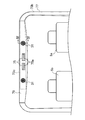
図1において、車両1は、ワンボックスタイプの車両である。インストルメントパネル3は、車室内前部に配設され、エンジンルーム(不図示)と車室内とを区画するダッシュパネルの後側(車室内側)に装備されている。インストルメントパネル3は、運転席が車両右側に位置する右ハンドル仕様車用のパネルの例である。
(Embodiment 1)
In FIG. 1, a
図1に示すように、車室内には、2つの前席5a,5b及び2つの後席5c,5dが設けられている。なお、以下の説明において、「前席」とは、前席5a,5b間のスペースも含むものである。
As shown in FIG. 1, two
フロントウィンドガラス1bが、インストルメントパネル3の前端部近傍から、後方に向けて上側に傾斜した姿勢で設けられている。インストルメントパネル3は、フロントウィンドガラス1bの下端部近傍から後方へ延びる上面部3aと、上面部3aの後端縁から湾曲しつつ下方へ延びる後面部3bとを有する。
The
インストルメントパネル3内には、破線で示すように前方空調装置本体21(HVAC)が配置されている。インストルメントパネル3の後面部3bの車幅方向中間部には、前方空調装置本体21からの温風や冷風などの温調空気を前席5a,5bに向けて吹き出すセンタエア吹出口23が、左右一対に並べて設けられている。インストルメントパネル3の左右両端部には、センタエア吹出口23に対応する高さ位置に、温調空気を前席5a,5bに向けて吹き出すサイドエア吹出口25が形成されている。
A front air conditioner main body 21 (HVAC) is disposed in the
また、インストルメントパネル3には、これら車室内空調用の吹出口23,25に加え、フロントウィンドガラス1bの結露による曇りを除去するための温調空気を吹き出すデフロスタ用吹出口27が形成されている。なお、図示を省略するが、インストルメントパネル3内には、吹出口23,25,27をそれぞれ前方空調装置本体21に接続する前席用空調ダクトが設けられている。
Further, in addition to the
各々のサイドエア吹出口25の直ぐ上側には、第2スピーカユニット41がそれぞれ設けられている。第2スピーカユニット41の正面側は、両サイドエア吹出口25と同様に前席5a,5b方向に向いている。第2スピーカユニット41は、図3に示すように、インストルメントパネル3の後面部3bの開口部3cに嵌め入れられたスピーカグリル43と、スピーカグリル43の奥側(即ち、インストルメントパネル3の内側)に配置されたツイータースピーカ45(高音用スピーカ)と、ツイータースピーカ45を支持し、ボルト等でインストルメントパネル3に取り付けられるプレート47からなる。ツイータースピーカ45は小型なものであるため、スピーカグリル43を嵌め入れる開口部3cはサイドエア吹出口25よりも狭い面積で足り、後述する第1スピーカユニット31用のスピーカ開口部37aに比較してもかなり狭い面積で足りる。そのため、インストルメントパネル3に設ける開口部3cの大きさが小さくて済み、意匠性及び設計自由度の向上に有用である。なお、図3に示す第2スピーカユニット41の構造は一例に過ぎず、高音用スピーカを有する他の構造のスピーカユニットでもよい。
A
図1及び図2に示すように、右側後席5cの後方の車室内(即ち、車両1の右後部)には、空調装置本体71(HVAC)が設けられている。図1に示すように、空調装置本体71からの温調空気を後席5c,5dに導く空調ダクト73が、車幅方向右側に設けられている。空調ダクト73は、車両側面のリヤサイドパネル1dの車室内側を上下方向に延びる第1空調ダクト73aと、サイドパネル1eの車室内側上部を前後方向に延びる第2空調ダクト73bと、ルーフ1cの前後方向中間部分で、車室内側を車幅方向に延びる第3空調ダクト73cとを接続した状態で一体的に有する。空調ダクト73の下流端部分である第3空調ダクト73cの前後方向位置は、前席5a,5bと後席5c,5dとの間で、かつ上方に位置付けられている。このため、着座者の邪魔にならず、車室内のスペースを有効に活用することができる。第3空調ダクト73cの車幅方向中央に対応する箇所には、後席5c,5dに向けて温調空気を吹き出すように、2つの吹出口75が左右に並んで設けられている。なお、図1では分かりやすいように図示を省略したが、図2に示すように、第1空調ダクト73a及び第2空調ダクト73bの車室内側面は、内張材77で覆われ、第3空調ダクト73cは、カバーダクト79で覆われている。吹出口75にはルーバー75aが設けられ、空調の風向きを調整できるようになっている。
As shown in FIGS. 1 and 2, an air conditioner main body 71 (HVAC) is provided in the passenger compartment behind the right
上述した空調装置本体71と空調ダクト73と吹出口75とで、空調装置7(後方用空調装置)が構成されている。
The air conditioner
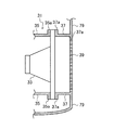
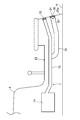
吹出口75の車幅方向外側位置にそれぞれ第1スピーカユニット31が設けられている。図4に示すように、第1スピーカユニット31は、内部にフルレンジスピーカ33を備える。フルレンジスピーカ33の背面側(車室内前方)には、第1スピーカダクト35が設けられている。第1スピーカダクト35は、フルレンジスピーカ33の背面側から車室内前方に延び、先端が第3空調ダクト73cの途中に接続されている。フルレンジスピーカ33の正面側(車室内後方)には、前後方向に延びる第2スピーカダクト37が設けられている。図4に示すように、第2スピーカダクト37は、空調ダクト73cを覆うカバーダクト79に一体的に形成されている。フルレンジスピーカ33は、フレーム外周縁部で第1スピーカダクト35のフランジ部35aと第2スピーカダクト37のフランジ部37aとに挟まれて固定されている。後席5c,5dに向いて開口した第2スピーカダクト37のスピーカ開口部37aに、スピーカグリル39が設けられている。スピーカグリル39は、上記第2スピーカダクト37と同様に、カバーダクト79に一体的に形成されている。なお、第2スピーカダクト37は第1スピーカダクト35よりも短い長さに設定してあり、中高音が周波数を乱されることなく伝わるように設定してある。この第2スピーカダクト37を設けることで、第2スピーカダクト37の内壁に反射する音を調整して、中高音を整えるようにすることも可能であり、設計自由度が向上する。
The
このように、実施形態1のオーディオシステムでは、第1スピーカダクト35と第3空調ダクト73cとが、フルレンジスピーカ33のバックキャビティとして機能するので、低音を効率よく共鳴させて低音の音質を向上させることができる。
Thus, in the audio system of
また、第1スピーカダクト35と第2スピーカダクト37との間にフルレンジスピーカ33が設けられて両者が連通しないようになっているため、フルレンジスピーカ33の正面側から発する音と背面側から発する音との干渉を抑制することができ、良質な音を得られる。
Further, since the
また、インストルメントパネル3内に設けられるのはツイータースピーカ45であるので、インストルメントパネル3に大きな開口部3cを設ける必要がなく、意匠性に優れる。さらに、ツイータースピーカ45を車室前部にその正面側が前席5a,5bを向くように設けるとともに、車室内の中央付近にフルレンジスピーカ33の正面側が後席5c,5dを向くように設けている。これにより、比較的指向性が強い高音が着座者の前方或いは左右から伝わってくるとともに、比較的指向性が低い低音が車室内に拡がって伝わってくることとなり、高音と低音との干渉を低減できて、立体的に臨場感あふれる音響効果が得られる。この構成により、本発明では、従来ドアに設けていた低音用のスピーカを設けることなく、優れた音響効果を得られる。
Moreover, since it is the
(実施形態2)
実施形態2を、図5〜図7に基づいて説明する。実施形態2では、実施形態1と異なる部分のみ説明する。
(Embodiment 2)
A second embodiment will be described with reference to FIGS. In the second embodiment, only parts different from the first embodiment will be described.
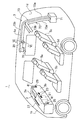
実施形態2では、図5に示すように、空調装置本体71に2本の空調ダクト73,73′が接続されている。一方の空調ダクト73は、車両側面のリヤサイドパネル1dの車室内側を上下方向に延びる第1空調ダクト73aと、サイドパネル1eの車室内側上方を前後方向に延びる第2空調ダクト73bとを一体的に有し、実施形態1の第3空調ダクト73cを省いた構造からなる。他方の空調ダクト73′は、車両側面のリヤサイドパネル1dの車室内側を上下方向に延びる第1空調ダクト73a′と、第1空調ダクト73a′の先端から左側に向けて延びた後、サイドパネル1eの車室内側上方を前後方向に延びる第2空調ダクト73b′とを一体的に有している。すなわち、空調ダクト73,73′が車室内の右側と左側とに配設されるように、右後部の空調装置本体71に接続されている。なお、図5では、左側に延びる空調ダクト73′の図示を第2空調ダクト73b′の途中から省略するものとする。
In the second embodiment, as shown in FIG. 5, two
第2空調ダクト73b,73b′の先端に、車室側方から車室内の中央方向(後席方向)に向けて開口する吹出口75が設けられ、第2空調ダクト73b,73b′の前後方向中間部分に、第1スピーカユニット31が設けられている。なお、図5では、第1スピーカユニット31を右側一方のみ図示しているが、他方(左側)のサイドパネル1eの車室内側を延びる第2空調ダクト73b′にも同様に設けられている。
At the front end of the second
図6及び図7に示すように、ルーフ1c内側のトップシーリング9の左右両側に設けられた開口部に第2スピーカダクト37が取り付けられ、第2スピーカダクト37にスピーカグリル39が嵌め入れられている。第1スピーカダクト35は、空調ダクト73bに接続されている。第2スピーカダクト37と第1スピーカダクト35との間に、フルレンジスピーカ33が固定されている。なお、図5では、トップシーリング9やドアトリム9aを省略して示す。
As shown in FIGS. 6 and 7, the
実施形態2のオーディオシステムにおいても、実施形態1と同様な効果を得られる。また、実施形態2では、ルーフ1cの車室内側に空調ダクト73や第1スピーカユニット31を設けないので、車室内において、ルーフ1cまでの高さを有効に活用できる。
In the audio system of the second embodiment, the same effect as that of the first embodiment can be obtained. In the second embodiment, since the
(実施形態3)
実施形態3を、図8〜図9に基づいて説明する。実施形態3では、実施形態1と異なる部分のみ説明する。
(Embodiment 3)
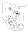
実施形態3では、空調装置7の空調装置本体71を、前方空調装置本体21としてインストルメントパネル3内に設けるようにしたものである。具体的には、車室内床部1f(フロア)にはセンターコンソール29が、インストルメントパネル3の下側から前席5a,5bの間を通って、前後方向に延びて設けられている。センターコンソール29の内部に空調ダクト73が配設されている。センターコンソール29の後面29aに、空調ダクト73の吹出口75が設けられている。
In the third embodiment, the
第1スピーカユニット31は、センターコンソール29の内部に設けられている。第1スピーカユニット31は、実施形態1と略同様な構造であり、構造の詳細な説明は省略する。
The
第1スピーカユニット31の第1スピーカダクト35が、空調ダクト73の途中に接続されている。第1スピーカユニット31のフルレンジスピーカ33の正面側が、空調ダクト73の吹出口75と上下に並んで後席5c,5dの着座者の足元に向いている。
The
この構成によると、第1スピーカダクト35及び空調ダクト73がバックキャビティとして機能するので、低音を効率よく共鳴させて低音の広がりを実現させることができる。また、第1スピーカダクト35の太さ及び長さを調整することで、音響特性を自由に調整できる。且つ第1スピーカユニット31が、センターコンソール29内に収納されているので、第1スピーカユニット31が露出せず意匠性に優れる。
According to this structure, since the
なお、第1スピーカユニット31全体がセンターコンソール29内に収納されるように設けたが、この位置に限られるものではない。例えば、前席5a,5bの下面とフロア1fとの間のスペースを利用して、この位置に第1スピーカユニット31を設けてもよい。具体的には、第1スピーカユニット31のフルレンジスピーカ33を上記スペースに設けて、フルレンジスピーカ33の背面側に第1スピーカダクト35を設け、該第1スピーカダクト35をセンターコンソール29内の空調ダクト73に左右から接続する。或いは、逆に、空調ダクト73を前席5a,5bの下面とフロア1fとの間のスペースに通して、フルレンジスピーカ33がセンターコンソール29の後面29a側に設けられるようにしてもよい。
Although the entire
また、上述した実施形態1及び2と同様に、フルレンジスピーカ33の正面側に第2スピーカダクト37を設けるようにしてもよい。この場合は、フルレンジスピーカ33を奥側(車室前方側)に位置付けて、第2スピーカダクト37の先端がセンターコンソール29の後面29aから飛び出さないようにすると、意匠上好ましい。
Further, similarly to the first and second embodiments described above, the
なお、実施形態3においては、空調装置本体71が実施形態1及び2の前方空調装置本体21の空調機能を兼用するように、前方空調装置本体21に代わって空調装置本体71をインストルメントパネル3内に設けたものであり、前方空調装置本体21と同様に、この空調装置本体71に前席用空調ダクト(図示省略)が連結され、センタエア吹出口23、サイドエア吹出口25及びデフロスタ用吹出口27と接続されている。
In the third embodiment, the
実施形態3は、実施形態1と同様な効果を有する。さらに、車室内後部に空調装置本体71を設けることができないタイプの車両にも適用することができる。
The third embodiment has the same effect as the first embodiment. Further, the present invention can be applied to a type of vehicle in which the air conditioner
(その他の実施形態)
実施形態1では、音が着座者の前側左右から聞こえることを狙いとして、第2スピーカユニット41をサイドエア吹出口25の近傍に配置しているが、この位置に限られない。例えば、デフロスタ用吹出口27の近辺、或いは、デフロスタ用吹出口27に通じる前席用空調ダクト(図示省略)に設けてもよい。或いは、サイドエア吹出口25とデフロスタ用吹出口27の両方に設けてもよい。または、サイドエア吹出口25内に第2スピーカユニット41を設けてもよい。
(Other embodiments)
In the first embodiment, the
また、実施形態1では、第1スピーカユニット31の第1スピーカダクト35を第3空調ダクト73cに接続するように設けたが、これに限られるものではなく、例えば、第1スピーカダクト35を第2空調ダクト73bや第1空調ダクト73aに接続してもよい。
In the first embodiment, the
また、実施形態2において、第1スピーカユニット31を車室の両サイドに設けるようにしたが、これに限られるものではなく、例えば、第1スピーカユニット31を実施形態1のように、前席5a,5bと後席5c,5dとの間に設けて第1スピーカダクト35を延ばし、第2空調ダクト73b,73b′に接続するようにしてもよい。
In the second embodiment, the
また、実施形態1及び2において、空調装置本体71は車両1の右後部に1つ設けるようにしたが、これに限られるものではなく、左後部にも空調装置本体を設けて、それぞれの空調装置本体に空調ダクトを接続してもよい。かかる場合、実施形態1のように、左右の空調ダクトを第3空調ダクト73cで合流させるようにしてもよい。
In the first and second embodiments, one air conditioner
また、実施形態1〜3において、第1スピーカユニット31と吹出口75とを入れ替えたものでもよい。
In
また、実施形態1及び2において、第2スピーカダクト37を省略して、フルレンジスピーカ33の正面側のすぐ近くにスピーカグリル39を設けてもよい。
In the first and second embodiments, the
以上説明したように、本発明は、自動車などの車両に設けられる空調用ダクトにスピーカを取り付けた車両用オーディオシステムに有用である。 As described above, the present invention is useful for a vehicle audio system in which a speaker is attached to an air conditioning duct provided in a vehicle such as an automobile.
1 車両
1c ルーフ
1f フロア(車室内床部)
3 インストルメントパネル
5a,5b 前席
5c,5d 後席
7 空調装置
29 センターコンソール
31 第1スピーカユニット
33 フルレンジスピーカ
35 第1スピーカダクト
37 第2スピーカダクト
41 第2スピーカユニット
45 ツイータースピーカ(高音用スピーカ)
71 空調装置本体
73,73′ 空調ダクト
75 吹出口
1
3
71 Air-
Claims (7)
上記空調装置(7)は、空調装置本体(71)と、上記後席(5c,5d)に対して設けられた吹出口(75)と、該吹出口(75)と該空調装置本体(71)とを連結する空調ダクト(73)とを有し、
上記スピーカユニット(31,41)は、上記後席(5c,5d)に対して設けられた第1スピーカユニット(31)と、上記車室前方のインストルメントパネル(3)内に設けられた第2スピーカユニット(41)とを有し、
上記第1スピーカユニット(31)は、正面側が上記後席(5c,5d)に向くとともに背面側が上記空調ダクト(73)に通じるように位置付けられたフルレンジスピーカ(33)を内部に有し、
上記第2スピーカユニット(41)は、正面側が上記前席(5a,5b)に向くように位置付けられた高音用スピーカ(45)を内部に有することを特徴とする車両用オーディオシステム。 A vehicle audio system comprising an air conditioner (7) and a speaker unit (31, 41) in a vehicle (1) having a front seat (5a, 5b) and a rear seat (5c, 5d) in the passenger compartment. And
The air conditioner (7) includes an air conditioner main body (71), an air outlet (75) provided to the rear seats (5c, 5d), the air outlet (75), and the air conditioner main body (71 Air conditioning duct (73) connecting the
The speaker unit (31, 41) includes a first speaker unit (31) provided for the rear seats (5c, 5d) and a first speaker unit (3) provided in the instrument panel (3) in front of the passenger compartment. 2 speaker units (41)
The first speaker unit (31) includes a full-range speaker (33) positioned so that the front side faces the rear seat (5c, 5d) and the back side leads to the air conditioning duct (73).
The vehicular audio system characterized in that the second speaker unit (41) has a loudspeaker (45) positioned so that the front side faces the front seat (5a, 5b).
上記第1スピーカユニット(31)は、上記フルレンジスピーカ(33)の背面側に位置して上記空調ダクト(73)に接続された第1スピーカダクト(35)を備え、
上記フルレンジスピーカ(33)の背面側が上記第1スピーカダクト(35)を介して上記空調ダクト(73)に通じていることを特徴とする車両用オーディオシステム。 In claim 1,
The first speaker unit (31) includes a first speaker duct (35) connected to the air conditioning duct (73) located on the back side of the full-range speaker (33),
The vehicular audio system, wherein a rear side of the full-range speaker (33) communicates with the air-conditioning duct (73) through the first speaker duct (35).
上記第1スピーカユニット(31)は、上記フルレンジスピーカ(33)の正面側に第2スピーカダクト(37)を備え、
上記第2スピーカダクト(37)の先端が上記後席(5c,5d)に向くように設けられていることを特徴とする車両用オーディオシステム。 In claim 2,
The first speaker unit (31) includes a second speaker duct (37) on the front side of the full-range speaker (33),
An audio system for a vehicle, characterized in that the second speaker duct (37) is provided such that a tip of the second speaker duct (37) faces the rear seat (5c, 5d).
上記第1スピーカダクト(35)と上記第2スピーカダクト(37)とが上記フルレンジスピーカ(33)で仕切られて、互いのスピーカダクト(35,37)が連通しないように構成されていることを特徴とする車両用オーディオシステム。 In claim 3,
The first speaker duct (35) and the second speaker duct (37) are partitioned by the full-range speaker (33) so that the speaker ducts (35, 37) do not communicate with each other. An audio system for vehicles.
上記空調装置(7)の空調装置本体(71)が車室後部に設けられ、
上記空調ダクト(73)が上記前席(5a,5b)と上記後席(5c,5d)との間に設けられ、
上記吹出口(75)が上記後席(5c,5d)に向いていることを特徴とする車両用オーディオシステム。 In any one of Claims 1 thru | or 4,
The air conditioner body (71) of the air conditioner (7) is provided at the rear of the passenger compartment,
The air conditioning duct (73) is provided between the front seat (5a, 5b) and the rear seat (5c, 5d),
The vehicular audio system, wherein the air outlet (75) faces the rear seat (5c, 5d).
センターコンソール(29)が、上記インストルメントパネル(3)の下側から後方に延びて設けられ、
上記空調装置(7)の上記空調装置本体(71)が、上記インストルメントパネル(3)内に設けられ、
上記空調装置(7)の上記空調ダクト(73)が、上記センターコンソール(29)内に設けられ、
上記第1スピーカユニット(31)の上記フルレンジスピーカ(33)及び上記第1スピーカダクト(35)が上記センターコンソール(29)内に設けられ、
上記第1スピーカダクト(35)が上記センターコンソール(29)内の上記空調ダクト(73)に接続されていることを特徴とする車両用オーディオシステム。 In any one of claims 2 to 4,
A center console (29) is provided extending rearward from the lower side of the instrument panel (3),
The air conditioner body (71) of the air conditioner (7) is provided in the instrument panel (3),
The air conditioning duct (73) of the air conditioning device (7) is provided in the center console (29),
The full speaker (33) and the first speaker duct (35) of the first speaker unit (31) are provided in the center console (29),
The vehicular audio system, wherein the first speaker duct (35) is connected to the air conditioning duct (73) in the center console (29).
上記第1スピーカユニット(31)が、上記車室内のフロア(1f)或いはルーフ(1c)に設けられていることを特徴とする車両用オーディオシステム。 In any one of Claims 1 thru | or 6,
The vehicular audio system, wherein the first speaker unit (31) is provided on a floor (1f) or a roof (1c) in the vehicle interior.
Priority Applications (1)
| Application Number | Priority Date | Filing Date | Title |
|---|---|---|---|
| JP2014156965A JP2016032995A (en) | 2014-07-31 | 2014-07-31 | Vehicular audio system |
Applications Claiming Priority (1)
| Application Number | Priority Date | Filing Date | Title |
|---|---|---|---|
| JP2014156965A JP2016032995A (en) | 2014-07-31 | 2014-07-31 | Vehicular audio system |
Publications (1)
| Publication Number | Publication Date |
|---|---|
| JP2016032995A true JP2016032995A (en) | 2016-03-10 |
Family
ID=55452109
Family Applications (1)
| Application Number | Title | Priority Date | Filing Date |
|---|---|---|---|
| JP2014156965A Pending JP2016032995A (en) | 2014-07-31 | 2014-07-31 | Vehicular audio system |
Country Status (1)
| Country | Link |
|---|---|
| JP (1) | JP2016032995A (en) |
Citations (5)
| Publication number | Priority date | Publication date | Assignee | Title |
|---|---|---|---|---|
| JPS626157U (en) * | 1985-06-28 | 1987-01-14 | ||
| JPS63155855U (en) * | 1987-04-01 | 1988-10-13 | ||
| JPH10243493A (en) * | 1997-02-25 | 1998-09-11 | Sony Corp | On-vehicle acoustic equipment |
| JP2009090868A (en) * | 2007-10-10 | 2009-04-30 | Calsonic Kansei Corp | Vehicular air-conditioner |
| JP2009159120A (en) * | 2007-12-25 | 2009-07-16 | Toyota Industries Corp | Vehicle speaker |
-
2014
- 2014-07-31 JP JP2014156965A patent/JP2016032995A/en active Pending
Patent Citations (5)
| Publication number | Priority date | Publication date | Assignee | Title |
|---|---|---|---|---|
| JPS626157U (en) * | 1985-06-28 | 1987-01-14 | ||
| JPS63155855U (en) * | 1987-04-01 | 1988-10-13 | ||
| JPH10243493A (en) * | 1997-02-25 | 1998-09-11 | Sony Corp | On-vehicle acoustic equipment |
| JP2009090868A (en) * | 2007-10-10 | 2009-04-30 | Calsonic Kansei Corp | Vehicular air-conditioner |
| JP2009159120A (en) * | 2007-12-25 | 2009-07-16 | Toyota Industries Corp | Vehicle speaker |
Similar Documents
| Publication | Publication Date | Title |
|---|---|---|
| US9428033B2 (en) | Air-conditioning apparatus for vehicle | |
| JP4665229B2 (en) | Air conditioner for vehicles | |
| JP5124157B2 (en) | Traveling vehicle with cabin | |
| JP4387719B2 (en) | Air conditioner for vehicles | |
| JP2016032995A (en) | Vehicular audio system | |
| JP2016022843A (en) | Duct with loudspeaker | |
| JP2004090682A (en) | Drain hose protective structure of on-vehicle air-conditioning case | |
| JP2009061949A (en) | Vehicular air conditioner | |
| JP2003175776A (en) | Moving means provided with speaker and air duct | |
| JP2006256402A (en) | Car rear parcel structure | |
| JPH11115448A (en) | Air conditioner for vehicle | |
| CN206900278U (en) | Vehicle | |
| JP2016025506A (en) | Duct with speaker | |
| CN114424582A (en) | Improved speaker assembly and system for a vehicle | |
| JP2016082446A (en) | Duct with speaker | |
| JP2007302027A (en) | Air conditioner for vehicle | |
| JPH0525289Y2 (en) | ||
| JP2016025507A (en) | Duct with speaker | |
| JP2016025508A (en) | Duct with speaker | |
| US6726557B2 (en) | Vehicle having a sound-radiating element | |
| JP2010245890A (en) | In-vehicle speaker apparatus | |
| JP6399286B2 (en) | Vehicle air conditioner | |
| JP5995170B2 (en) | Air conditioning unit for vehicles | |
| JP2018111338A (en) | Speaker device of vehicle, and vehicle | |
| JP3710004B2 (en) | Duct structure for vehicle air conditioning |
Legal Events
| Date | Code | Title | Description |
|---|---|---|---|
| A621 | Written request for application examination |
Free format text: JAPANESE INTERMEDIATE CODE: A621 Effective date: 20170427 |
|
| A977 | Report on retrieval |
Free format text: JAPANESE INTERMEDIATE CODE: A971007 Effective date: 20180214 |
|
| A131 | Notification of reasons for refusal |
Free format text: JAPANESE INTERMEDIATE CODE: A131 Effective date: 20180403 |
|
| A02 | Decision of refusal |
Free format text: JAPANESE INTERMEDIATE CODE: A02 Effective date: 20181016 |