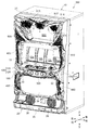
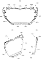
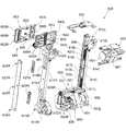
以下、本発明の好ましい実施形態について図面を参照して説明する。まず、図1〜図3を参照しながら、遊技機の実施形態としてスロットマシンSMの概要について説明する。なお、本実施形態において、図1の各矢印で示す方向をそれぞれ、上下方向、前後方向、左右方向として説明する。本実施形態のスロットマシンSMは、箱状の基体部10と、前面扉20とを主体に構成される。基体部10は前方に開口部10aを有する箱状に形成され、基体部10の前部に前面扉20が取り付けられる。前面扉20は、ヒンジ機構5a,5bを用いて基体部10の左前部に枢支され、基体部10の開口部10aを揺動開閉可能に構成される。
Hereinafter, preferred embodiments of the present invention will be described with reference to the drawings. First, an outline of a slot machine SM as an embodiment of the gaming machine will be described with reference to FIGS. In the present embodiment, the directions indicated by the arrows in FIG. 1 will be described as the up-down direction, the front-rear direction, and the left-right direction, respectively. The slot machine SM of the present embodiment is mainly composed of a box-shaped base portion 10 and a front door 20. The base portion 10 is formed in a box shape having an opening 10 a in the front, and the front door 20 is attached to the front portion of the base portion 10. The front door 20 is pivotally supported on the left front portion of the base portion 10 using the hinge mechanisms 5a and 5b, and is configured to be able to swing open and close the opening portion 10a of the base portion 10.
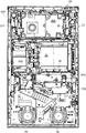
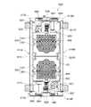
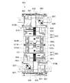
基体部10の内部中央には、4つのリール12a,12b,12c,12dを備えるリールユニット11が設けられ、前面扉20に設けられたリール表示窓22を通して4つのリール12a,12b,12c,12dに描かれている図柄を視認することができるようになっている。基体部10の内部下側には、スロットマシンSMに搭載された種々の装置に電源を供給する電源ユニット13、およびメダルを貯留しておくホッパー14aを備えるメダル払出装置14が設けられる。基体部10の背板部の上側内面には、スロットマシンSMで行われる遊技を全体的に制御する主制御装置15が設けられる。ヒンジ機構5a,5bが設けられる基体部10の左側板部の上側内面には、スロットマシンSMの演出制御として演出決定処理を行う副制御装置50が設けられる。
A reel unit 11 including four reels 12a, 12b, 12c, and 12d is provided in the center of the base portion 10, and the four reels 12a, 12b, 12c, and 12d are passed through a reel display window 22 provided on the front door 20. It is possible to visually recognize the pattern drawn on the screen. A medal payout device 14 including a power supply unit 13 for supplying power to various devices mounted on the slot machine SM and a hopper 14a for storing medals is provided on the lower side inside the base body portion 10. On the upper inner surface of the back plate portion of the base body portion 10, a main control device 15 that controls the game played in the slot machine SM as a whole is provided. On the upper inner surface of the left side plate portion of the base portion 10 where the hinge mechanisms 5a and 5b are provided, a sub-control device 50 that performs effect determination processing as effect control of the slot machine SM is provided.
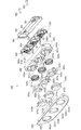
前面扉20には前面枠21が形成されており、前面枠21の略中央部にリール表示窓22が設けられる。前面扉20の前面側中央には、リール表示窓22の下方に位置して操作パネル100が設けられる。操作パネル100の上面側には、遊技を行うためのベットスイッチユニット200、演出スイッチユニット31、およびメダル投入口32aを有するメダル投入ユニット32が取り付けられる。操作パネル100の前面側には、遊技を行うためのスタートスイッチ33、およびストップスイッチユニット300が取り付けられる。また、前面扉20の前面側中央には、リール表示窓22の側方に位置して左右の上部サイドランプ400,410が取り付けられる。
A front frame 21 is formed on the front door 20, and a reel display window 22 is provided at a substantially central portion of the front frame 21. An operation panel 100 is provided in the center of the front side of the front door 20 so as to be positioned below the reel display window 22. On the upper surface side of the operation panel 100, a bet switch unit 200 for playing a game, an effect switch unit 31, and a medal insertion unit 32 having a medal insertion slot 32a are attached. A start switch 33 and a stop switch unit 300 for playing a game are attached to the front side of the operation panel 100. In addition, left and right upper side lamps 400 and 410 are attached to the front center of the front door 20 so as to be located on the side of the reel display window 22.
前面扉20の前面側上部には、画像表示装置501および演出装置511を備えた上部マスクユニット500が取り付けられる。前面扉20の前面側下部には、左右の下部サイドランプ450,460、装飾パネル34、およびメダル払出装置14から払い出されたメダルが貯留される受け皿35が設けられる。
An upper mask unit 500 including an image display device 501 and a rendering device 511 is attached to the upper part on the front side of the front door 20. In the lower part on the front side of the front door 20, left and right lower side lamps 450 and 460, a decorative panel 34, and a tray 35 for storing medals paid out from the medal paying device 14 are provided.
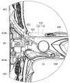
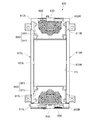
前面扉20が基体部10の開口部10aを閉じた状態では、前面扉20の後面側が基体部10の内部側に位置する。前面扉20の後面側には、リール表示窓22に取り付けられるエスカッション36、メダル投入口32aに投入されたメダルの選別を行うメダルセレクタ37、左右の下部スピーカーユニット38,39、シャッター装置600、中継基板ケースユニット700、および配線カバー800が設けられる。また、前面扉20における上部マスクユニット500の後面側には、スロットマシンSMの演出制御として各種演出装置の演出制御処理を行う演出制御ユニット506が取り付けられる。
In a state where the front door 20 closes the opening 10 a of the base body 10, the rear surface side of the front door 20 is located on the inner side of the base body 10. On the rear side of the front door 20, an escutcheon 36 attached to the reel display window 22, a medal selector 37 for selecting medals inserted into the medal insertion slot 32a, left and right lower speaker units 38, 39, a shutter device 600, and a relay A substrate case unit 700 and a wiring cover 800 are provided. An effect control unit 506 that performs effect control processing of various effect devices as effect control of the slot machine SM is attached to the rear surface side of the upper mask unit 500 in the front door 20.
[操作パネルの構成]
次に、本実施形態に係る操作パネル100について図4〜図8を参照して説明する。操作パネル100は、図4〜図6に示すように、上パネル部材110と、前パネル部材120とを有して構成され、前面枠21の略中央部に形成された操作ユニット取付部23に取り付けられる。操作ユニット取付部23は、図6および図8に示すように、リール表示窓22の下方において、リール表示窓22(前面扉20)の前面側から前方に突出するとともに左右方向に延びるステージ状に形成される。
[Operation panel configuration]
Next, the operation panel 100 according to the present embodiment will be described with reference to FIGS. As shown in FIGS. 4 to 6, the operation panel 100 includes an upper panel member 110 and a front panel member 120, and has an operation unit mounting portion 23 formed at a substantially central portion of the front frame 21. It is attached. As shown in FIGS. 6 and 8, the operation unit mounting portion 23 has a stage shape that protrudes forward from the front side of the reel display window 22 (front door 20) and extends in the left-right direction below the reel display window 22. It is formed.
図6に示すように、操作ユニット取付部23の上面部左側には、ベットスイッチユニット200の外周形状に合わせた穴状のベットスイッチ取付部23aが形成され、このベットスイッチ取付部23aにベットスイッチユニット200が上方を向いて取り付けられる。操作ユニット取付部23の上面部中央には、演出スイッチユニット31の外周形状に合わせた穴状の演出スイッチ取付部23bが形成され、この演出スイッチ取付部23bに演出スイッチユニット31が上方を向いて取り付けられる。操作ユニット取付部23の上面部右側には、メダル投入ユニット32の外周形状に合わせた穴状のメダルユニット取付部23cが形成され、このメダルユニット取付部23cにメダル投入ユニット32が取り付けられる。
As shown in FIG. 6, a hole-shaped bet switch mounting portion 23a that matches the outer peripheral shape of the bet switch unit 200 is formed on the left side of the upper surface of the operation unit mounting portion 23, and the bet switch mounting portion 23a has a bet switch. The unit 200 is mounted facing upward. In the center of the upper surface of the operation unit mounting portion 23, a hole-shaped effect switch mounting portion 23b that matches the outer peripheral shape of the effect switch unit 31 is formed, and the effect switch unit 31 faces upward at the effect switch mounting portion 23b. It is attached. A hole-shaped medal unit mounting portion 23c that matches the outer peripheral shape of the medal insertion unit 32 is formed on the right side of the upper surface of the operation unit mounting portion 23, and the medal insertion unit 32 is attached to the medal unit mounting portion 23c.
操作ユニット取付部23の前面部中央には、ストップスイッチユニット300の外周形状に合わせた穴状のストップスイッチ取付部23dが形成され、このストップスイッチ取付部23dにストップスイッチユニット300が前方を向いて取り付けられる。また、操作ユニット取付部23の前面部左側には、スタートスイッチ33が取り付けられる。
A hole-shaped stop switch mounting portion 23d that matches the outer peripheral shape of the stop switch unit 300 is formed in the center of the front surface of the operation unit mounting portion 23, and the stop switch unit 300 faces the front to the stop switch mounting portion 23d. It is attached. A start switch 33 is mounted on the left side of the front surface of the operation unit mounting portion 23.
上パネル部材110は、図5および図6に示すように、樹脂材料を用いて左右方向に延びる薄板状に形成され、ベットスイッチユニット200、演出スイッチユニット31、およびメダル投入ユニット32とともに、操作ユニット取付部23の上面部に取り付けられる。上パネル部材110は、操作ユニット取付部23の上面部に、当該上面部におけるベットスイッチ取付部23a、演出スイッチ取付部23b、およびメダルユニット取付部23cを除いた部分を覆うように取り付けられる。
As shown in FIGS. 5 and 6, the upper panel member 110 is formed in a thin plate shape that extends in the left-right direction using a resin material, and together with the bet switch unit 200, the effect switch unit 31, and the medal insertion unit 32, It is attached to the upper surface part of the attachment part 23. The upper panel member 110 is attached to the upper surface portion of the operation unit attachment portion 23 so as to cover a portion of the upper surface portion excluding the bet switch attachment portion 23a, the effect switch attachment portion 23b, and the medal unit attachment portion 23c.
上パネル部材110の左側には、ベットスイッチユニット200の中間部が挿通されるベットスイッチ挿通穴111が形成される。上パネル部材110におけるベットスイッチ挿通穴111の縁部は、ベットスイッチユニット200の上側外周部に重なるように覆われて操作ユニット取付部23に固定されるようになっている。上パネル部材110の中央には、演出スイッチユニット31の中間部が挿通される演出スイッチ挿通穴112が形成される。上パネル部材110における演出スイッチ挿通穴112の縁部は、演出スイッチユニット31の上側外周部に重なるように覆われて操作ユニット取付部23に固定されるようになっている。上パネル部材110の左側には、メダル投入ユニット32の中間部が挿通されるメダル投入ユニット挿通部113が形成される。上パネル部材110におけるメダル投入ユニット挿通部113の縁部は、メダル投入ユニット32の上側外周部に重なるように覆われて操作ユニット取付部23に固定されるようになっている。
A bet switch insertion hole 111 through which an intermediate portion of the bet switch unit 200 is inserted is formed on the left side of the upper panel member 110. An edge portion of the bet switch insertion hole 111 in the upper panel member 110 is covered and fixed to the operation unit mounting portion 23 so as to overlap the upper outer peripheral portion of the bet switch unit 200. In the center of the upper panel member 110, an effect switch insertion hole 112 through which an intermediate portion of the effect switch unit 31 is inserted is formed. An edge portion of the effect switch insertion hole 112 in the upper panel member 110 is covered and fixed to the operation unit mounting portion 23 so as to overlap the upper outer peripheral portion of the effect switch unit 31. On the left side of the upper panel member 110, a medal insertion unit insertion portion 113 into which an intermediate portion of the medal insertion unit 32 is inserted is formed. The edge portion of the medal insertion unit insertion portion 113 in the upper panel member 110 is covered and fixed to the operation unit mounting portion 23 so as to overlap the upper outer peripheral portion of the medal insertion unit 32.
前パネル部材120は、図5に示すように、樹脂材料を用いて左右方向に延びる薄型のカバー形状に形成され、ストップスイッチユニット300とともに、操作ユニット取付部23の前面部に取り付けられる。前パネル部材120は、操作ユニット取付部23の前面部に、当該前面部におけるストップスイッチ取付部23d、およびスタートスイッチ33の取付部を除いた部分を覆うように取り付けられる。
As shown in FIG. 5, the front panel member 120 is formed in a thin cover shape that extends in the left-right direction using a resin material, and is attached to the front surface portion of the operation unit attachment portion 23 together with the stop switch unit 300. The front panel member 120 is attached to the front surface portion of the operation unit attachment portion 23 so as to cover a portion excluding the stop switch attachment portion 23d and the start switch 33 attachment portion in the front surface portion.
前パネル部材120の左側には、スタートスイッチ33が挿通されるスタートスイッチ挿通穴121が形成される。前パネル部材120の中央には、ストップスイッチユニット300の中間部が挿通されるストップスイッチ挿通穴122が形成される。前パネル部材120におけるストップスイッチ挿通穴122の縁部は、ストップスイッチユニット300の前側外周部(後述のパネル押さえ部333)に重なるように覆われて操作ユニット取付部23に固定されるようになっている。前パネル部材120の右側には、前面扉20に設けられた鍵穴部分を露出させる鍵露出穴123が形成される。
A start switch insertion hole 121 through which the start switch 33 is inserted is formed on the left side of the front panel member 120. In the center of the front panel member 120, a stop switch insertion hole 122 into which an intermediate portion of the stop switch unit 300 is inserted is formed. An edge portion of the stop switch insertion hole 122 in the front panel member 120 is covered and fixed to the operation unit mounting portion 23 so as to overlap a front outer peripheral portion (a panel pressing portion 333 described later) of the stop switch unit 300. ing. On the right side of the front panel member 120, a key exposure hole 123 that exposes a keyhole portion provided in the front door 20 is formed.
前パネル部材120の上端部には、上パネル部材110の前端部を覆う覆い部124が形成される。覆い部124は、図8に示すように、前パネル部材120の上端部から後方へ屈曲するように延びて、上パネル部材110の前部と前パネル部材120の上部とが段付きで互い違いに重なるように、操作ユニット取付部23の上面部に取り付けられた上パネル部材110の前端部および、当該前端部に繋がる上パネル部材110の左右端部を覆うように形成される。
A cover 124 that covers the front end of the upper panel member 110 is formed at the upper end of the front panel member 120. As shown in FIG. 8, the cover 124 extends from the upper end portion of the front panel member 120 so as to bend backward, and the front portion of the upper panel member 110 and the upper portion of the front panel member 120 are stepped alternately. It is formed so as to cover the front end portion of the upper panel member 110 attached to the upper surface portion of the operation unit attachment portion 23 and the left and right end portions of the upper panel member 110 connected to the front end portion so as to overlap.
図5に示すように、前面枠21の左側には、操作ユニット取付部23の左方に位置して左固定部材取付部25が形成される。左固定部材取付部25の前面側には、前パネル部材120の左端部を覆って固定する左固定部材160が取り付けられる。前面枠21の左側における左固定部材取付部25の上方には、リール表示窓22の左方に位置して左サイドランプ取付部27が形成される。左サイドランプ取付部27の前面側には、左上部サイドランプ400が取り付けられる。図7に示すように、左上方を向いて凹むように形成された前パネル部材120の左上端部には、左上部サイドランプ400の前下部に下方を向いて尖るように形成されたパネル固定部402が当接し、前パネル部材120の左上端部が上方へ動かないように固定される。
As shown in FIG. 5, a left fixing member attachment portion 25 is formed on the left side of the front frame 21 so as to be located to the left of the operation unit attachment portion 23. A left fixing member 160 that covers and fixes the left end portion of the front panel member 120 is attached to the front surface side of the left fixing member attachment portion 25. A left side lamp mounting portion 27 is formed at the left side of the reel display window 22 above the left fixing member mounting portion 25 on the left side of the front frame 21. An upper left side lamp 400 is mounted on the front side of the left side lamp mounting portion 27. As shown in FIG. 7, at the upper left end portion of the front panel member 120 formed so as to be recessed toward the upper left, the panel is fixed to the front lower portion of the upper left side lamp 400 so as to point downward. The part 402 contacts and is fixed so that the upper left end of the front panel member 120 does not move upward.
左固定部材160は、図5に示すように、樹脂材料を用いて三角形のカバー形状に形成され、ネジ等の固定手段(図示せず)を用いて、左固定部材取付部25の前面側に取り付け固定される。なお、左固定部材取付部25の右方に前パネル部材120が配置され、左固定部材取付部25の上方に左上部サイドランプ400が配置され、左固定部材取付部25の下方に左下部サイドランプ450が配置される。左固定部材160の右側には、前パネル部材120の左端部を前面側から覆って固定する左パネル固定部161が形成される。左固定部材160の左側には、左上部サイドランプ400の下端部(図7における下カバー部409b)および左下部サイドランプ450の上端部(図7における上カバー部459a)を前面側から覆って固定する左サイドランプ固定部162が形成される。
As shown in FIG. 5, the left fixing member 160 is formed in a triangular cover shape using a resin material, and is attached to the front side of the left fixing member mounting portion 25 using a fixing means (not shown) such as a screw. Mounting is fixed. The front panel member 120 is disposed on the right side of the left fixing member mounting portion 25, the upper left side lamp 400 is disposed above the left fixing member mounting portion 25, and the lower left side is positioned below the left fixing member mounting portion 25. A lamp 450 is arranged. A left panel fixing portion 161 that covers and fixes the left end portion of the front panel member 120 from the front side is formed on the right side of the left fixing member 160. On the left side of the left fixing member 160, the lower end portion of the upper left side lamp 400 (lower cover portion 409b in FIG. 7) and the upper end portion of the lower left side lamp 450 (upper cover portion 459a in FIG. 7) are covered from the front side. A left side lamp fixing portion 162 to be fixed is formed.
図5に示すように、前面枠21の右側には、操作ユニット取付部23の右方に位置して右固定部材取付部26が形成される。右固定部材取付部26の前面側には、前パネル部材120の右端部を覆って固定する右固定部材170が取り付けられる。前面枠21の右側における右固定部材取付部26の上方には、リール表示窓22の右方に位置して右サイドランプ取付部28が形成される。右サイドランプ取付部28の前面側には、右上部サイドランプ410が取り付けられる。左上部サイドランプ400と同様に、右上方を向いて凹むように形成された前パネル部材120の右上端部には、右上部サイドランプ410の前下部に下方を向いて尖るように形成されたパネル固定部442(図18を参照)が当接し、前パネル部材120の右上端部が上方へ動かないように固定される。
As shown in FIG. 5, a right fixing member attachment portion 26 is formed on the right side of the front frame 21 so as to be located to the right of the operation unit attachment portion 23. A right fixing member 170 that covers and fixes the right end portion of the front panel member 120 is attached to the front side of the right fixing member attachment portion 26. A right side lamp mounting portion 28 is formed at the right side of the reel display window 22 and above the right fixing member mounting portion 26 on the right side of the front frame 21. An upper right side lamp 410 is mounted on the front side of the right side lamp mounting portion 28. Similar to the upper left side lamp 400, the front panel member 120 formed so as to be recessed toward the upper right is formed so as to be pointed downward toward the lower front of the upper right side lamp 410. The panel fixing portion 442 (see FIG. 18) contacts and is fixed so that the upper right end portion of the front panel member 120 does not move upward.
右固定部材170は、図5に示すように、樹脂材料を用いて左固定部材160と左右対称の三角形のカバー形状に形成され、ネジ等の固定手段(図示せず)を用いて、右固定部材取付部26の前面側に取り付け固定される。なお、右固定部材取付部26の右方に前パネル部材120が配置され、右固定部材取付部26の上方に右上部サイドランプ410が配置され、右固定部材取付部26の下方に右下部サイドランプ460が配置される。右固定部材170の左側には、前パネル部材120の右端部を前面側から覆って固定する右パネル固定部171が形成される。右固定部材170の右側には、右上部サイドランプ410の下端部(図18における下カバー部439b)および右下部サイドランプ460の上端部(図示せず)を前面側から覆って固定する右サイドランプ固定部172が形成される。
As shown in FIG. 5, the right fixing member 170 is formed in a triangular symmetrical shape with the left fixing member 160 using a resin material, and is fixed to the right using fixing means (not shown) such as screws. It is fixedly attached to the front side of the member mounting portion 26. The front panel member 120 is disposed on the right side of the right fixing member mounting portion 26, the upper right side lamp 410 is disposed above the right fixing member mounting portion 26, and the lower right side is positioned below the right fixing member mounting portion 26. A lamp 460 is disposed. On the left side of the right fixing member 170, a right panel fixing portion 171 that covers and fixes the right end portion of the front panel member 120 from the front side is formed. On the right side of the right fixing member 170, a right side that covers and fixes the lower end portion of the upper right side lamp 410 (lower cover portion 439b in FIG. 18) and the upper end portion (not shown) of the lower right side lamp 460 from the front side. A lamp fixing portion 172 is formed.
なお、左サイドランプ取付部27および右サイドランプ取付部28の上方に位置する前面枠21の上部には、上部マスクユニット500の外周形状に合わせた枠状の上部マスク取付部24が形成される。上部マスク取付部24の前面側には、上部マスクユニット500が前方を向くように取り付けられる。
A frame-shaped upper mask mounting portion 24 that matches the outer peripheral shape of the upper mask unit 500 is formed on the upper portion of the front frame 21 located above the left side lamp mounting portion 27 and the right side lamp mounting portion 28. . The upper mask unit 500 is attached to the front side of the upper mask attaching portion 24 so as to face the front.
以上のように構成される操作パネル100を、前面枠21の操作ユニット取付部23に取り付けるには、まず、上パネル部材110を操作ユニット取付部23の上面部に載置する。次に、図5に示すように、ベットスイッチユニット200、演出スイッチユニット31、およびメダル投入ユニット32を、操作ユニット取付部23のベットスイッチ取付部23a、演出スイッチ取付部23b、およびメダルユニット取付部23cに取り付ける。
In order to attach the operation panel 100 configured as described above to the operation unit attachment portion 23 of the front frame 21, first, the upper panel member 110 is placed on the upper surface portion of the operation unit attachment portion 23. Next, as shown in FIG. 5, the bet switch unit 200, the effect switch unit 31, and the medal insertion unit 32 are replaced with the bet switch attachment portion 23 a, the effect switch attachment portion 23 b, and the medal unit attachment portion of the operation unit attachment portion 23. Attach to 23c.
このとき、ベットスイッチユニット200は、上パネル部材110のベットスイッチ挿通穴111に挿通され、上パネル部材110におけるベットスイッチ挿通穴111の縁部を覆って固定するように、ネジ等の固定手段(図示せず)を用いてベットスイッチ取付部23aに取り付け固定される。演出スイッチユニット31は、上パネル部材110の演出スイッチ挿通穴112に挿通され、上パネル部材110における演出スイッチ挿通穴112の縁部を覆って固定するように、ネジ等の固定手段(図示せず)を用いて演出スイッチ取付部23bに取り付け固定される。メダル投入ユニット32は、上パネル部材110のメダル投入ユニット挿通部113に挿通され、上パネル部材110におけるメダル投入ユニット挿通部113の縁部を覆って固定するように、ネジ等の固定手段(図示せず)を用いてメダルユニット取付部23cに取り付け固定される。
At this time, the bet switch unit 200 is inserted through the bet switch insertion hole 111 of the upper panel member 110 and covers and fixes the edge of the bet switch insertion hole 111 of the upper panel member 110 so as to fix it (such as screws). (Not shown) is attached and fixed to the bed switch mounting portion 23a. The effect switch unit 31 is inserted into the effect switch insertion hole 112 of the upper panel member 110, and is fixed by means such as screws (not shown) so as to cover and fix the edge of the effect switch insertion hole 112 in the upper panel member 110. ) Is attached and fixed to the effect switch mounting portion 23b. The medal insertion unit 32 is inserted into the medal insertion unit insertion portion 113 of the upper panel member 110 and is fixed by a fixing means such as a screw so as to cover and fix the edge of the medal insertion unit insertion portion 113 in the upper panel member 110 (see FIG. (Not shown) is attached and fixed to the medal unit attaching portion 23c.
次に、前パネル部材120のスタートスイッチ挿通穴121にスタートスイッチ33を挿通させて、前パネル部材120を操作ユニット取付部23の前面部にセットする。なお、スタートスイッチ33は、前パネル部材120をセットする前に、操作ユニット取付部23の前面部左側に取り付けられる。次に、ストップスイッチユニット300を、操作ユニット取付部23のストップスイッチ取付部23dに取り付ける。このとき、ストップスイッチユニット300は、前パネル部材120のストップスイッチ挿通穴122に挿通され、前パネル部材120におけるストップスイッチ挿通穴122の縁部を覆って固定するように、ネジ等の固定手段(図示せず)を用いてストップスイッチ取付部23dに取り付け固定される。
Next, the start switch 33 is inserted into the start switch insertion hole 121 of the front panel member 120, and the front panel member 120 is set on the front surface portion of the operation unit mounting portion 23. The start switch 33 is attached to the left side of the front surface of the operation unit attachment portion 23 before setting the front panel member 120. Next, the stop switch unit 300 is attached to the stop switch attachment portion 23 d of the operation unit attachment portion 23. At this time, the stop switch unit 300 is inserted through the stop switch insertion hole 122 of the front panel member 120 and covers the edge of the stop switch insertion hole 122 in the front panel member 120 so as to cover and fix the fixing means (such as screws). (Not shown) is attached and fixed to the stop switch attaching portion 23d.
次に、左上部サイドランプ400を左サイドランプ取付部27の前面側に取り付け、右上部サイドランプ410を右サイドランプ取付部28の前面側に取り付ける。このとき、図7に示すように、左上部サイドランプ400のパネル固定部402が前パネル部材120の左上端部に当接し、前パネル部材120の左上端部が上方へ動かないように固定される。また、右上部サイドランプ410のパネル固定部442(図18を参照)が前パネル部材120の右上端部に当接し、前パネル部材120の右上端部が上方へ動かないように固定される。
Next, the upper left side lamp 400 is attached to the front side of the left side lamp attachment portion 27, and the upper right side lamp 410 is attached to the front side of the right side lamp attachment portion 28. At this time, as shown in FIG. 7, the panel fixing portion 402 of the upper left side lamp 400 abuts the upper left end portion of the front panel member 120, and the upper left end portion of the front panel member 120 is fixed so as not to move upward. The Moreover, the panel fixing | fixed part 442 (refer FIG. 18) of the upper right side lamp 410 contact | abuts to the upper right end part of the front panel member 120, and it fixes so that the upper right end part of the front panel member 120 may not move upwards.
次に、上部マスクユニット500を上部マスク取付部24の前面側に取り付ける。このとき、左上部サイドランプ400および右上部サイドランプ410の上端部が、上部マスクユニット500の下部に前面側から覆われて固定される。
Next, the upper mask unit 500 is attached to the front side of the upper mask attaching portion 24. At this time, the upper ends of the upper left side lamp 400 and the upper right side lamp 410 are covered and fixed to the lower part of the upper mask unit 500 from the front side.
次に、左固定部材160を左固定部材取付部25の前面側に取り付け、右固定部材170を右固定部材取付部26の前面側に取り付ける。このとき、図4に示すように、左固定部材160の左パネル固定部161は、前パネル部材120の左端部を前面側から覆って固定する。また、左固定部材160の左サイドランプ固定部162は、左上部サイドランプ400の下端部(図7における下カバー部409b)および左下部サイドランプ450の上端部(図7における上カバー部459a)を前面側から覆って固定する。一方、右固定部材170の右パネル固定部171は、前パネル部材120の右端部を前面側から覆って固定する。また、右固定部材170の右サイドランプ固定部172は、右上部サイドランプ410の下端部(図18における下カバー部439b)および右下部サイドランプ460の上端部(図示せず)を前面側から覆って固定する。
Next, the left fixing member 160 is attached to the front surface side of the left fixing member attachment portion 25, and the right fixing member 170 is attached to the front surface side of the right fixing member attachment portion 26. At this time, as shown in FIG. 4, the left panel fixing portion 161 of the left fixing member 160 covers and fixes the left end portion of the front panel member 120 from the front side. The left side lamp fixing portion 162 of the left fixing member 160 includes a lower end portion of the upper left side lamp 400 (lower cover portion 409b in FIG. 7) and an upper end portion of the lower left side lamp 450 (upper cover portion 459a in FIG. 7). Cover and fix from the front side. On the other hand, the right panel fixing portion 171 of the right fixing member 170 covers and fixes the right end portion of the front panel member 120 from the front side. The right side lamp fixing portion 172 of the right fixing member 170 has a lower end portion (lower cover portion 439b in FIG. 18) of the upper right side lamp 410 and an upper end portion (not shown) of the right lower side lamp 460 from the front side. Cover and fix.
このようにして、ネジ等の固定手段を直接用いることなく、上パネル部材110が操作ユニット取付部23の上面部に取り付け固定されるとともに、前パネル部材120の覆い部124が上パネル部材110の前端部および左右端部を覆う状態で、前パネル部材120が操作ユニット取付部23の前面部に取り付け固定される。これにより、上パネル部材110の前端部および左右端部が前パネル部材120の覆い部124に覆われるため、工具等を用いて、操作ユニット取付部23の上面部と上パネル部材110との間に隙間が形成され、操作ユニット取付部23のベットスイッチ取付部23aや演出スイッチ取付部23b等からスロットマシンSMの内部に不正にアクセスされるのを防止することができる。
In this manner, the upper panel member 110 is attached and fixed to the upper surface portion of the operation unit attachment portion 23 without directly using fixing means such as screws, and the cover portion 124 of the front panel member 120 is attached to the upper panel member 110. The front panel member 120 is attached and fixed to the front surface portion of the operation unit attachment portion 23 in a state of covering the front end portion and the left and right end portions. As a result, the front end portion and the left and right end portions of the upper panel member 110 are covered with the cover portion 124 of the front panel member 120, so that a tool or the like is used between the upper surface portion of the operation unit mounting portion 23 and the upper panel member 110. Thus, the slot machine SM can be prevented from being illegally accessed from the bet switch mounting portion 23a and the effect switch mounting portion 23b of the operation unit mounting portion 23.
また、前パネル部材120の左右端部が左固定部材160および右固定部材170に覆われて固定されるため、工具等を用いて、操作ユニット取付部23の前面部と前パネル部材120との間に隙間が形成され、操作ユニット取付部23のストップスイッチ取付部23d等からスロットマシンSMの内部に不正にアクセスされるのを防止することができる。また、左上部サイドランプ400の下端部が左固定部材160に覆われて固定されるため、工具等を用いて、左上部サイドランプ400の下端部と左サイドランプ取付部27との間に隙間が形成され、スロットマシンSMの内部に不正にアクセスされるのを防止することができる。また、右上部サイドランプ410の下端部が右固定部材170に覆われて固定されるため、工具等を用いて、右上部サイドランプ410の下端部と右サイドランプ取付部28との間に隙間が形成され、スロットマシンSMの内部に不正にアクセスされるのを防止することができる。同様に、左下部サイドランプ450および右下部サイドランプ460の上端部に隙間が形成され、スロットマシンSMの内部に不正にアクセスされるのを防止することができる。
Further, since the left and right end portions of the front panel member 120 are covered and fixed by the left fixing member 160 and the right fixing member 170, a tool or the like is used to connect the front surface portion of the operation unit mounting portion 23 and the front panel member 120. A gap is formed between them, and unauthorized access to the inside of the slot machine SM from the stop switch mounting portion 23d or the like of the operation unit mounting portion 23 can be prevented. Further, since the lower end portion of the upper left side lamp 400 is covered and fixed by the left fixing member 160, a gap is formed between the lower end portion of the upper left side lamp 400 and the left side lamp mounting portion 27 using a tool or the like. Can be prevented, and unauthorized access to the inside of the slot machine SM can be prevented. Further, since the lower end portion of the upper right side lamp 410 is covered and fixed by the right fixing member 170, a gap is formed between the lower end portion of the upper right side lamp 410 and the right side lamp attachment portion 28 using a tool or the like. Can be prevented, and unauthorized access to the inside of the slot machine SM can be prevented. Similarly, a gap is formed at the upper ends of the lower left side lamp 450 and the lower right side lamp 460, and unauthorized access to the inside of the slot machine SM can be prevented.
また、左上部サイドランプ400のパネル固定部402が前パネル部材120の左上端部に当接し、前パネル部材120の左上端部が上方へ動かないように固定される。同様に、右上部サイドランプ410のパネル固定部442が前パネル部材120の右上端部に当接し、前パネル部材120の右上端部が上方へ動かないように固定される。これにより、上パネル部材110および前パネル部材120を操作ユニット取付部23から取り外すには、左固定部材160および右固定部材170だけでなく、上部マスクユニット500と、左上部サイドランプ400および右上部サイドランプ410とを、この順に取り外す必要がある。そのため、上パネル部材110および前パネル部材120を取り外すのが煩雑であるため、上パネル部材110および前パネル部材120の不正な取り外しを防止することができる。
Further, the panel fixing portion 402 of the upper left side lamp 400 contacts the upper left end portion of the front panel member 120, and the upper left end portion of the front panel member 120 is fixed so as not to move upward. Similarly, the panel fixing portion 442 of the upper right side lamp 410 abuts on the upper right end portion of the front panel member 120 and is fixed so that the upper right end portion of the front panel member 120 does not move upward. Accordingly, in order to remove the upper panel member 110 and the front panel member 120 from the operation unit mounting portion 23, not only the left fixing member 160 and the right fixing member 170 but also the upper mask unit 500, the upper left side lamp 400, and the upper right portion. It is necessary to remove the side lamp 410 in this order. Therefore, since it is complicated to remove the upper panel member 110 and the front panel member 120, unauthorized removal of the upper panel member 110 and the front panel member 120 can be prevented.
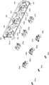
[ベットスイッチユニットの構成]
次に、本実施形態に係るベットスイッチユニット200について図9〜図14を参照して説明する。ベットスイッチユニット200は、図9〜図11に示すように、第1操作部材201と、第2操作部材204と、第3操作部材207と、ボタン収容部材211と、ボタンカバー部材231と、センサユニット部240と、照光ユニット部260と、接点ユニット部280とを有して構成される。
[Bet switch unit configuration]
Next, the bet switch unit 200 according to the present embodiment will be described with reference to FIGS. As shown in FIGS. 9 to 11, the bet switch unit 200 includes a first operation member 201, a second operation member 204, a third operation member 207, a button housing member 211, a button cover member 231 and a sensor. The unit 240 is configured to include an illumination unit 260 and a contact unit 280.
第1操作部材201は、図11に示すように、樹脂材料を用いて筒状に形成され、ボタン収容部材211の第1ボタン収容部212に上下にスライド移動自在に収容される。第1操作部材201の一端(上端)には、透光性を有する円板状のマックスベットボタン部202が結合されており、遊技者によって外部からマックスベットボタン部202を押す操作が行われる。第1操作部材201の他端(下端)には、板状の検出片部203が第1操作部材201の他端側(下側)に突出して形成されており、マックスベットボタン部202を押す操作が行われたときに、この検出片部203がセンサユニット部240によって検出されるようになっている。また、第1操作部材201の他端側外周部には、第1操作部材201がボタン収容部材211から抜け出すのを防止する爪状の抜け止め部201aが形成されている。
As shown in FIG. 11, the first operation member 201 is formed in a cylindrical shape using a resin material, and is housed in the first button housing portion 212 of the button housing member 211 so as to be slidable up and down. One end (upper end) of the first operation member 201 is coupled with a translucent disc-shaped max bet button portion 202, and an operation of pushing the max bet button portion 202 from the outside by a player is performed. At the other end (lower end) of the first operation member 201, a plate-like detection piece 203 is formed to protrude to the other end side (lower side) of the first operation member 201, and the max bet button portion 202 is pushed. When the operation is performed, the detection piece 203 is detected by the sensor unit 240. Further, a claw-shaped retaining portion 201 a that prevents the first operating member 201 from slipping out of the button housing member 211 is formed on the outer peripheral portion on the other end side of the first operating member 201.
第2操作部材204は、図11に示すように、樹脂材料を用いて傘状に形成され、ボタン収容部材211の第2ボタン収容部215に上下にスライド移動自在に収容される。第2操作部材204の一端(上端)には、平板状のシングルベットボタン部205が形成されており、遊技者によって外部からシングルベットボタン部205を押す操作が行われる。第2操作部材204の他端側(下側)には、棒状の当接部206が形成されており、シングルベットボタン部205を押す操作が行われたときに、この当接部206が接点ユニット部280の第1接触子287に当接するようになっている。また、第2操作部材204の他端側外周部には、第2操作部材204がボタン収容部材211から抜け出すのを防止するフランジ状の抜け止め部204aが形成されている。
As shown in FIG. 11, the second operation member 204 is formed in an umbrella shape using a resin material, and is housed in the second button housing portion 215 of the button housing member 211 so as to be slidable up and down. A flat single bet button portion 205 is formed at one end (upper end) of the second operation member 204, and an operation of pushing the single bet button portion 205 from the outside by a player is performed. A rod-like contact portion 206 is formed on the other end side (lower side) of the second operation member 204. When an operation of pressing the single bet button portion 205 is performed, the contact portion 206 is a contact point. The unit 280 comes into contact with the first contact 287. Further, a flange-shaped retaining portion 204 a that prevents the second operating member 204 from coming out of the button housing member 211 is formed on the outer peripheral portion on the other end side of the second operating member 204.
第3操作部材207は、図11に示すように、樹脂材料を用いて傘状に形成され、ボタン収容部材211の第3ボタン収容部217に上下にスライド移動自在に収容される。第3操作部材207の一端(上端)には、平板状の精算ボタン部208が形成されており、遊技者によって外部から精算ボタン部208を押す操作が行われる。第3操作部材207の他端側(下側)には、棒状の当接部209が形成されており、精算ボタン部208を押す操作が行われたときに、この当接部209が接点ユニット部280の第2接触子288に当接するようになっている。また、第3操作部材207の他端側外周部には、第3操作部材207がボタン収容部材211から抜け出すのを防止するフランジ状の抜け止め部207aが形成されている。
As shown in FIG. 11, the third operation member 207 is formed in an umbrella shape using a resin material, and is housed in the third button housing portion 217 of the button housing member 211 so as to be slidable up and down. A flat adjustment button portion 208 is formed at one end (upper end) of the third operation member 207, and an operation of pushing the adjustment button portion 208 from the outside by the player is performed. A rod-shaped contact portion 209 is formed on the other end side (lower side) of the third operation member 207, and when the adjustment button portion 208 is pressed, the contact portion 209 is a contact unit. The second contact 288 of the portion 280 is in contact with the second contact 288. Further, a flange-shaped retaining portion 207 a that prevents the third operating member 207 from coming out of the button housing member 211 is formed on the outer peripheral portion on the other end side of the third operating member 207.
ボタン収容部材211は、図11に示すように、樹脂材料を用いて箱状に形成される。ボタン収容部材211には、第1ボタン収容部212と、第2ボタン収容部215と、第3ボタン収容部217とが三角形状に並んで形成される。言い換えると、第1ボタン収容部212がボタン収容部材211の右側に形成され、第2ボタン収容部215および第3ボタン収容部217がボタン収容部材211の左側に前後に並んで形成される。
As shown in FIG. 11, the button accommodating member 211 is formed in a box shape using a resin material. In the button accommodating member 211, a first button accommodating portion 212, a second button accommodating portion 215, and a third button accommodating portion 217 are formed side by side in a triangular shape. In other words, the first button accommodating portion 212 is formed on the right side of the button accommodating member 211, and the second button accommodating portion 215 and the third button accommodating portion 217 are formed side by side on the left side of the button accommodating member 211.
第1ボタン収容部212の一端側(上側)の内部に、第1操作部材201が収容され、第1ボタン収容部212の一端(上端)に開口形成された第1ボタン露出部213を介して、マックスベットボタン部202が外部に露出するようになっている(図9を参照)。第1ボタン収容部212は、第1ボタン露出部213においてマックスベットボタン部202を外部に露出させた状態で、マックスベットボタン部202が押された操作状態の操作位置と、マックスベットボタン部202が非操作状態の非操作位置とに、第1操作部材201を上下にスライド移動可能に収容保持する。なお、第1操作部材201が操作位置に位置すると、マックスベットボタン部202の外周部が第1ボタン収容部212の内側の段差部に当接し、第1操作部材201が非操作位置に位置すると、第1操作部材201の抜け止め部201aが第1ボタン収容部212の内側の段差部に当接するようになっている。
The first operation member 201 is accommodated inside one end side (upper side) of the first button accommodating portion 212, and the first button exposing portion 213 is opened at one end (upper end) of the first button accommodating portion 212. The max bet button section 202 is exposed to the outside (see FIG. 9). The first button accommodating portion 212 has an operation position in which the max bet button portion 202 is pressed and the max bet button portion 202 in a state where the max bet button portion 202 is exposed to the outside in the first button exposing portion 213. The first operation member 201 is accommodated and held so as to be slidable up and down at the non-operation position in the non-operation state. When the first operation member 201 is located at the operation position, the outer peripheral portion of the max bet button portion 202 abuts on the stepped portion inside the first button housing portion 212, and when the first operation member 201 is located at the non-operation position. The retaining portion 201 a of the first operation member 201 is in contact with the stepped portion inside the first button housing portion 212.
第1ボタン収容部212の一端側(上側)の内部には、第1操作部材201とともに第1付勢バネ221が収容される。第1付勢バネ221は、圧縮コイルバネを用いて構成され、第1操作部材201が非操作位置に位置するように付勢力を加える。第1ボタン収容部212の他端(下端)には開口部214が形成され、ボタンカバー部材231の第1カバー部232がこの開口部214を覆うようになっている。第1ボタン収容部212の他端側(下側)の内部には、ボタンカバー部材231の第1カバー部232に取り付けられたセンサユニット部240および照光ユニット部260が収容される。なお、第1ボタン収容部212の外側部には、ボタンカバー部材231の係止穴部237に係止可能な係止爪部219が形成される。
A first urging spring 221 is accommodated together with the first operating member 201 inside one end (upper side) of the first button accommodating portion 212. The first biasing spring 221 is configured using a compression coil spring, and applies a biasing force so that the first operating member 201 is located at the non-operating position. An opening 214 is formed at the other end (lower end) of the first button accommodating portion 212, and the first cover portion 232 of the button cover member 231 covers the opening 214. The sensor unit 240 and the illumination unit 260 attached to the first cover 232 of the button cover member 231 are housed inside the other end side (lower side) of the first button housing part 212. A locking claw portion 219 that can be locked in the locking hole portion 237 of the button cover member 231 is formed on the outer side of the first button housing portion 212.
第2ボタン収容部215の内部に、第2操作部材204が収容され、第2ボタン収容部215の一端(上端)に開口形成された第2ボタン露出部216を介して、シングルベットボタン部205が外部に露出するようになっている(図9を参照)。第2ボタン収容部215は、第2ボタン露出部216においてシングルベットボタン部205を外部に露出させた状態で、シングルベットボタン部205が押された操作状態の操作位置と、シングルベットボタン部205が非操作状態の非操作位置とに、第2操作部材204を上下にスライド移動可能に収容保持する。なお、第2操作部材204が操作位置に位置すると、第2操作部材204の当接部206が接点ユニット部280の第1接触子287に当接し、第2操作部材204が非操作位置に位置すると、第2操作部材204の抜け止め部204aが第2ボタン収容部215の内側の段差部に当接するようになっている。
The second operation member 204 is accommodated in the second button accommodating portion 215, and the single bet button portion 205 is interposed through the second button exposing portion 216 formed in one end (upper end) of the second button accommodating portion 215. Is exposed to the outside (see FIG. 9). The second button accommodating portion 215 has an operation position in which the single bet button portion 205 is pressed and the single bet button portion 205 in a state where the single bet button portion 205 is exposed to the outside in the second button exposing portion 216. The second operation member 204 is accommodated and held so as to be slidable up and down at the non-operation position in the non-operation state. When the second operating member 204 is positioned at the operating position, the contact portion 206 of the second operating member 204 contacts the first contact 287 of the contact unit unit 280, and the second operating member 204 is positioned at the non-operating position. Then, the retaining portion 204 a of the second operation member 204 comes into contact with the step portion inside the second button housing portion 215.
第2ボタン収容部215の内部には、第2操作部材204とともに第2付勢バネ224が収容される。第2付勢バネ224は、圧縮コイルバネを用いて構成され、第2操作部材204が非操作位置に位置するように付勢力を加える。
A second urging spring 224 is housed in the second button housing portion 215 together with the second operation member 204. The second urging spring 224 is configured using a compression coil spring, and applies a urging force so that the second operation member 204 is located at the non-operation position.
第3ボタン収容部217の内部に、第3操作部材207が収容され、第3ボタン収容部217の一端(上端)に開口形成された第3ボタン露出部218を介して、精算ボタン部208が外部に露出するようになっている(図9を参照)。第3ボタン収容部217は、第3ボタン露出部218において精算ボタン部208を外部に露出させた状態で、精算ボタン部208が押された操作状態の操作位置と、精算ボタン部208が非操作状態の非操作位置とに、第3操作部材207を上下にスライド移動可能に収容保持する。なお、第3操作部材207が操作位置に位置すると、第3操作部材207の当接部209が接点ユニット部280の第2接触子288に当接し、第3操作部材207が非操作位置に位置すると、第3操作部材207の抜け止め部207aが第3ボタン収容部217の内側の段差部に当接するようになっている。
The third operation member 207 is accommodated in the third button accommodating portion 217, and the checkout button portion 208 is connected to the third button accommodating portion 217 through a third button exposing portion 218 formed at one end (upper end) of the third button accommodating portion 217. It is exposed to the outside (see FIG. 9). The third button accommodating portion 217 is in a state where the adjustment button portion 208 is pressed in the state where the adjustment button portion 208 is exposed to the outside in the third button exposure portion 218, and the adjustment button portion 208 is not operated. The third operating member 207 is accommodated and held slidably up and down at the non-operating position in the state. When the third operating member 207 is positioned at the operating position, the contact portion 209 of the third operating member 207 contacts the second contact 288 of the contact unit unit 280, and the third operating member 207 is positioned at the non-operating position. Then, the retaining portion 207 a of the third operating member 207 comes into contact with the stepped portion inside the third button housing portion 217.
第3ボタン収容部217の内部には、第3操作部材207とともに第3付勢バネ227が収容される。第3付勢バネ227は、圧縮コイルバネを用いて構成され、第3操作部材207が非操作位置に位置するように付勢力を加える。第2ボタン収容部215および第3ボタン収容部217の他端(下端)には開口部(図示せず)が形成され、補助カバー部材230がこの開口部を覆うようになっている。補助カバー部材230は、接点ユニット部280の外周形状に合わせた枠部を有する板状に形成され、第1カバー固定ネジ299aを用いてボタン収容部材211の他端側(下側)に取り付け固定される。図10に示すように、補助カバー部材230の下側には、接点ユニット部280が第2ボタン収容部215および第3ボタン収容部217の開口部と重なるように取り付けられる。接点ユニット部280の底部(後述の第2スイッチ基板収容部材296)は、ボタンカバー部材231の第2カバー部238に覆われて固定されるようになっている。
A third urging spring 227 is accommodated together with the third operating member 207 in the third button accommodating portion 217. The third biasing spring 227 is configured using a compression coil spring, and applies a biasing force so that the third operating member 207 is positioned at the non-operating position. An opening (not shown) is formed at the other end (lower end) of the second button accommodating portion 215 and the third button accommodating portion 217, and the auxiliary cover member 230 covers the opening. The auxiliary cover member 230 is formed in a plate shape having a frame portion matched to the outer peripheral shape of the contact unit portion 280, and is attached and fixed to the other end side (lower side) of the button housing member 211 using the first cover fixing screw 299a. Is done. As shown in FIG. 10, the contact unit portion 280 is attached to the lower side of the auxiliary cover member 230 so as to overlap the openings of the second button housing portion 215 and the third button housing portion 217. The bottom portion (second switch board housing member 296 described later) of the contact unit portion 280 is covered and fixed by the second cover portion 238 of the button cover member 231.
ボタンカバー部材231は、図10および図11に示すように、樹脂材料を用いて図示する形状に形成され、ボタン収容部材211(第1ボタン収容部212)の開口部214を覆う第1カバー部232と、接点ユニット部280の底部を覆う第2カバー部238とを有している。第1カバー部232の側部には、センサユニット部240の係合突起部252が係合可能な穴状のユニット係合部233が形成される。第1カバー部232の底部には、センサユニット部240のセンサ用コネクタ244を露出させるセンサコネクタ露出穴234と、照光ユニット部260のランプ用コネクタ263を露出させるランプコネクタ露出穴235とが形成される。第1カバー部232の一端側(上側)には、ネジ穴を有するユニット固定ボス236が形成される。ユニット係合部233にセンサユニット部240の係合突起部252が係合した状態で、第3カバー固定ネジ299cがセンサユニット部240と連結された照光ユニット部260のネジ挿通穴274に挿通されてユニット固定ボス236のネジ穴と螺合する。これにより、センサユニット部240および照光ユニット部260が第1カバー部232の内側に取り付け固定される。第1カバー部232の外側部には、ボタン収容部材211の係止爪部219が係止可能な係止穴部237が形成される。
As shown in FIGS. 10 and 11, the button cover member 231 is formed in a shape illustrated using a resin material, and covers a first cover portion that covers the opening 214 of the button storage member 211 (first button storage portion 212). 232 and a second cover portion 238 that covers the bottom of the contact unit portion 280. On the side of the first cover part 232, a hole-shaped unit engaging part 233 is formed in which the engaging projection part 252 of the sensor unit part 240 can be engaged. A sensor connector exposure hole 234 for exposing the sensor connector 244 of the sensor unit 240 and a lamp connector exposure hole 235 for exposing the lamp connector 263 of the illumination unit 260 are formed at the bottom of the first cover 232. The A unit fixing boss 236 having a screw hole is formed on one end side (upper side) of the first cover portion 232. With the engagement protrusion 252 of the sensor unit 240 engaged with the unit engagement part 233, the third cover fixing screw 299c is inserted into the screw insertion hole 274 of the illumination unit 260 connected to the sensor unit 240. And screwed into the screw holes of the unit fixing boss 236. Thereby, the sensor unit 240 and the illumination unit 260 are attached and fixed inside the first cover 232. On the outer side of the first cover part 232, a locking hole part 237 that can be locked by the locking claw part 219 of the button housing member 211 is formed.
第2カバー部238の底部には、第2カバー固定ネジ299bが挿通されるカバー固定穴239が形成される。第1カバー部232の係止穴部237にボタン収容部材211の係止爪部219を係止させた状態で、第2カバー固定ネジ299bをカバー固定穴239に挿通させて補助カバー部材230にネジ固定することにより、ボタンカバー部材231が補助カバー部材230を介してボタン収容部材211の他端側(下側)に取り付け固定される(図10を参照)。
A cover fixing hole 239 through which the second cover fixing screw 299b is inserted is formed at the bottom of the second cover portion 238. With the locking claw 219 of the button housing member 211 locked in the locking hole 237 of the first cover 232, the second cover fixing screw 299 b is inserted through the cover fixing hole 239 to the auxiliary cover member 230. By fixing with screws, the button cover member 231 is attached and fixed to the other end side (lower side) of the button accommodating member 211 via the auxiliary cover member 230 (see FIG. 10).
センサユニット部240および照光ユニット部260は、互いに略平行な向きで連結され、ボタンカバー部材231の第1カバー部232に取り付けられた状態で、ボタン収容部材211の第1ボタン収容部212に収容される。センサユニット部240は、マックスベットボタン部202が下方に押されて操作位置に移動した第1操作部材201の検出片部203を検出し、第1操作部材201のマックスベットボタン部202に対する操作検出信号を主制御装置15へ出力する。すなわち、センサユニット部240は、後述の中継基板710(図37を参照)を介して主制御装置15と電気的に接続される。一方、照光ユニット部260は、演出制御ユニット506から送信されたランプ制御信号に応じて、第1ボタン収容部212の内部からマックスベットボタン部202を透過する光を発光する。すなわち、照光ユニット部260は、演出制御ユニット506を介して副制御装置50と電気的に接続される。なお、第1ボタン収容部212の内部において、照光ユニット部260がセンサユニット部240の後側に重なるように配置される。
The sensor unit 240 and the illumination unit 260 are connected in a substantially parallel orientation and are accommodated in the first button accommodating portion 212 of the button accommodating member 211 while being attached to the first cover portion 232 of the button cover member 231. Is done. The sensor unit 240 detects the detection piece 203 of the first operation member 201 moved to the operation position when the max bet button 202 is pushed downward, and detects the operation of the first operation member 201 with respect to the max bet button 202. The signal is output to the main controller 15. That is, the sensor unit 240 is electrically connected to the main controller 15 via a relay board 710 (see FIG. 37) described later. On the other hand, the illumination unit 260 emits light that passes through the max bet button unit 202 from the inside of the first button housing unit 212 in accordance with the lamp control signal transmitted from the effect control unit 506. That is, the illumination unit 260 is electrically connected to the sub control device 50 via the effect control unit 506. Note that the illumination unit 260 is disposed inside the first button housing 212 so as to overlap the rear side of the sensor unit 240.
センサユニット部240は、図12〜図14に示すように、センサ基板241と、第1センサ基板保持部材246と、第2センサ基板保持部材256とを有して構成される。センサ基板241は、プリント基板の一方の実装面に配設されたフォトセンサを構成する発光素子242および受光素子243と、プリント基板の他方の実装面に配設されたセンサ用コネクタ244とを有して構成される。発光素子242および受光素子243は互いに対向するように配置され、発光素子242から射出された検出光を受光素子243で受光可能に構成される。センサ用コネクタ244は、中継基板710を介して主制御装置15と繋がるベットスイッチケーブル853(図37を参照)の主制御用コネクタ(図示せず)と嵌合接続されるようになっている。センサ基板241は、発光素子242から射出された検出光が第1操作部材201の検出片部203に遮られて受光素子243が非受光状態になると、第1操作部材201のマックスベットボタン部202に対する操作検出信号を主制御装置15へ出力する。
As shown in FIGS. 12 to 14, the sensor unit 240 includes a sensor substrate 241, a first sensor substrate holding member 246, and a second sensor substrate holding member 256. The sensor substrate 241 includes a light emitting element 242 and a light receiving element 243 that constitute a photosensor disposed on one mounting surface of the printed circuit board, and a sensor connector 244 disposed on the other mounting surface of the printed circuit board. Configured. The light emitting element 242 and the light receiving element 243 are arranged so as to face each other, and are configured such that the light receiving element 243 can receive the detection light emitted from the light emitting element 242. The sensor connector 244 is fitted and connected to a main control connector (not shown) of a bed switch cable 853 (see FIG. 37) connected to the main control device 15 via the relay board 710. When the detection light emitted from the light emitting element 242 is blocked by the detection piece portion 203 of the first operation member 201 and the light receiving element 243 is in a non-light receiving state, the sensor substrate 241 has the max bet button portion 202 of the first operation member 201. Is output to the main controller 15.
第1センサ基板保持部材246は、樹脂材料を用いて、センサ基板241の発光素子242および受光素子243を覆う箱状に形成される。第1センサ基板保持部材246の一端側(ベットスイッチユニット200における上側)には、センサ基板241の発光素子242を覆う発光素子収容部247と、センサ基板241の受光素子243を覆う受光素子収容部248とが、所定間隔(第1操作部材201の検出片部203が進入可能な間隔)だけ離れて形成される。発光素子収容部247と受光素子収容部248との間には、発光素子242の検出光を通過させる穴部とともに、第1操作部材201の検出片部203が進入可能な検出溝部249が形成される。第1センサ基板保持部材246の他端側(ベットスイッチユニット200における下側)には、先端部が第2センサ基板保持部材256の係合穴部256aに係合可能な係合ピン246aが形成される。第1センサ基板保持部材246の側部には、第2センサ基板保持部材256の係止穴部258に係止可能な係止突起部250が形成される。第1センサ基板保持部材246の外側には、照光ユニット部260の連結突起部275と嵌合可能な連結溝部251が形成される。第1センサ基板保持部材246の外側における連結溝部251と反対側の部分には、ボタンカバー部材231のユニット係合部233に係合可能な係合突起部252が形成される。
The first sensor substrate holding member 246 is formed in a box shape that covers the light emitting element 242 and the light receiving element 243 of the sensor substrate 241 using a resin material. On one end side of the first sensor substrate holding member 246 (upper side in the bed switch unit 200), a light emitting element accommodating portion 247 that covers the light emitting element 242 of the sensor substrate 241 and a light receiving element accommodating portion that covers the light receiving element 243 of the sensor substrate 241. 248 is formed at a predetermined interval (interval at which the detection piece portion 203 of the first operation member 201 can enter). Between the light emitting element accommodating part 247 and the light receiving element accommodating part 248, a detection groove part 249 into which the detection piece part 203 of the first operating member 201 can enter is formed together with a hole part through which the detection light of the light emitting element 242 passes. The On the other end side (the lower side of the bed switch unit 200) of the first sensor substrate holding member 246, an engagement pin 246a whose tip is engageable with the engagement hole portion 256a of the second sensor substrate holding member 256 is formed. Is done. On the side of the first sensor substrate holding member 246, a locking projection 250 that can be locked in the locking hole 258 of the second sensor substrate holding member 256 is formed. A connection groove 251 that can be fitted to the connection protrusion 275 of the illumination unit 260 is formed outside the first sensor substrate holding member 246. An engaging protrusion 252 that can be engaged with the unit engaging portion 233 of the button cover member 231 is formed on the outer side of the first sensor substrate holding member 246 on the side opposite to the connecting groove 251.
第2センサ基板保持部材256は、樹脂材料を用いて、センサ基板241の他方の実装面を覆う板状に形成される。第2センサ基板保持部材256の底部には、第1センサ基板保持部材246の係合ピン246aの先端部が係合可能な係合穴部256aが形成される。第2センサ基板保持部材256の中央部には、センサ基板241のセンサ用コネクタ244が挿通されるセンサコネクタ挿通穴257が形成される。第2センサ基板保持部材256の側部には、第1センサ基板保持部材246の係止突起部250が係止可能な係止穴部258が形成される。
The second sensor substrate holding member 256 is formed in a plate shape that covers the other mounting surface of the sensor substrate 241 using a resin material. At the bottom of the second sensor substrate holding member 256, an engagement hole portion 256a is formed in which the front end portion of the engagement pin 246a of the first sensor substrate holding member 246 can be engaged. A sensor connector insertion hole 257 through which the sensor connector 244 of the sensor substrate 241 is inserted is formed at the center of the second sensor substrate holding member 256. On the side of the second sensor substrate holding member 256, a locking hole portion 258 that can lock the locking projection 250 of the first sensor substrate holding member 246 is formed.
第1センサ基板保持部材246の係止突起部250が第2センサ基板保持部材256の係止穴部258に係止し、第1センサ基板保持部材246の係合ピン246aの先端部が第2センサ基板保持部材256の係合穴部256aに係合した状態で、第1センサ基板保持部材246と第2センサ基板保持部材256とが結合する。この状態で、センサ基板241に切欠き形成された係合部241aが第1センサ基板保持部材246の係合ピン246aの側部に係合し、センサ基板241が第1センサ基板保持部材246および第2センサ基板保持部材256の内側で保持される。
The locking projection 250 of the first sensor substrate holding member 246 is locked in the locking hole 258 of the second sensor substrate holding member 256, and the tip of the engagement pin 246a of the first sensor substrate holding member 246 is the second. The first sensor substrate holding member 246 and the second sensor substrate holding member 256 are coupled in a state where the sensor substrate holding member 256 is engaged with the engagement hole portion 256a. In this state, the engaging portion 241a formed in the sensor substrate 241 is engaged with the side portion of the engaging pin 246a of the first sensor substrate holding member 246, so that the sensor substrate 241 and the first sensor substrate holding member 246 It is held inside the second sensor substrate holding member 256.
照光ユニット部260は、図12〜図14に示すように、照光ランプ基板261と、拡散シート266と、第1ランプ基板保持部材271と、第2ランプ基板保持部材276とを有して構成される。照光ランプ基板261は、プリント基板の一方の実装面に配設された照光LEDランプ262と、プリント基板の他方の実装面に配設されたランプ用コネクタ263とを有して構成される。照光LEDランプ262は、第1ボタン収容部212の内部からマックスベットボタン部202を透過する光を発光可能に構成される。ランプ用コネクタ263は、演出制御ユニット506と繋がる照光ランプケーブル(図示せず)の副制御用コネクタ(図示せず)と嵌合接続されるようになっている。照光ランプ基板261は、演出制御ユニット506から送信されたランプ制御信号に応じて、照光LEDランプ262の発光制御を行う。
As illustrated in FIGS. 12 to 14, the illumination unit 260 includes an illumination lamp substrate 261, a diffusion sheet 266, a first lamp substrate holding member 271, and a second lamp substrate holding member 276. The The illumination lamp substrate 261 includes an illumination LED lamp 262 disposed on one mounting surface of the printed circuit board and a lamp connector 263 disposed on the other mounting surface of the printed circuit board. The illuminated LED lamp 262 is configured to be able to emit light that passes through the max bed button portion 202 from the inside of the first button housing portion 212. The lamp connector 263 is fitted and connected to a sub-control connector (not shown) of an illumination lamp cable (not shown) connected to the effect control unit 506. The illumination lamp substrate 261 performs light emission control of the illumination LED lamp 262 in accordance with the lamp control signal transmitted from the effect control unit 506.
第1ランプ基板保持部材271は、樹脂材料を用いて、照光ランプ基板261の照光LEDランプ262を覆う箱状に形成される。第1ランプ基板保持部材271の一端側(ベットスイッチユニット200における上側)には、照光LEDランプ262から発光した光を通過させる発光穴部272が形成される。拡散シート266は、発光穴部272を塞ぐように第1ランプ基板保持部材271の内側に取り付けられ、照光LEDランプ262から発光した光を拡散させるようになっている。第1ランプ基板保持部材271の他端側(ベットスイッチユニット200における下側)には、先端部が第2ランプ基板保持部材276の係合穴部276aに係合可能な係合ピン271aが形成される。第1ランプ基板保持部材271の側部には、第2ランプ基板保持部材276の係止穴部278に係止可能な係止突起部273が形成される。第1ランプ基板保持部材271の外側縁部近傍には、第3カバー固定ネジ299cが挿通されるネジ挿通穴274が形成される。
The first lamp substrate holding member 271 is formed in a box shape that covers the illumination LED lamp 262 of the illumination lamp substrate 261 using a resin material. A light emitting hole portion 272 that allows light emitted from the illumination LED lamp 262 to pass therethrough is formed on one end side of the first lamp substrate holding member 271 (upper side in the bed switch unit 200). The diffusion sheet 266 is attached to the inside of the first lamp substrate holding member 271 so as to close the light emitting hole 272, and diffuses light emitted from the illumination LED lamp 262. On the other end side (the lower side of the bed switch unit 200) of the first lamp board holding member 271, an engaging pin 271a whose tip part can be engaged with the engaging hole part 276a of the second lamp board holding member 276 is formed. Is done. A locking projection 273 that can be locked in the locking hole 278 of the second lamp substrate holding member 276 is formed on the side of the first lamp substrate holding member 271. A screw insertion hole 274 through which the third cover fixing screw 299c is inserted is formed in the vicinity of the outer edge portion of the first lamp substrate holding member 271.
第1ランプ基板保持部材271の他端には、センサユニット部240(第1センサ基板保持部材246)の連結溝部251と嵌合可能な連結突起部275が他端側(ベットスイッチユニット200における下側)に突出して形成される。第1センサ基板保持部材246の連結溝部251と第1ランプ基板保持部材271の連結突起部275とは、互いに嵌合した状態で、センサ用コネクタ244およびランプ用コネクタ263が主制御用コネクタおよび副制御用コネクタ(図示せず)との嵌合方向にずれた状態(例えば、センサ用コネクタ244またはランプ用コネクタ263の1つ分程度の長さだけずれた状態)で略平行に並ぶように、第1センサ基板保持部材246と第1ランプ基板保持部材271とを連結させる。
At the other end of the first lamp substrate holding member 271, a connecting projection 275 that can be fitted to the connecting groove 251 of the sensor unit 240 (first sensor substrate holding member 246) is provided at the other end (the bottom of the bed switch unit 200). Side). The connection groove 251 of the first sensor substrate holding member 246 and the connection protrusion 275 of the first lamp substrate holding member 271 are fitted to each other, and the sensor connector 244 and the lamp connector 263 are connected to the main control connector and the sub-connector. In a state of being shifted in a fitting direction with a control connector (not shown) (for example, a state of being shifted by a length corresponding to one of the connector for sensor 244 or the connector for lamp 263), The first sensor substrate holding member 246 and the first lamp substrate holding member 271 are connected.
第2ランプ基板保持部材276は、樹脂材料を用いて、照光ランプ基板261の他方の実装面を覆う板状に形成される。第2ランプ基板保持部材276の底部には、第1ランプ基板保持部材271の係合ピン271aの先端部が係合可能な係合穴部276aが形成される。第2ランプ基板保持部材276の中央部には、照光ランプ基板261のランプ用コネクタ263が挿通されるランプコネクタ挿通穴277が形成される。第2ランプ基板保持部材276の側部には、第1ランプ基板保持部材271の係止突起部273が係止可能な係止穴部278が形成される。
The second lamp substrate holding member 276 is formed in a plate shape that covers the other mounting surface of the illumination lamp substrate 261 using a resin material. At the bottom of the second lamp substrate holding member 276, an engagement hole 276a is formed in which the tip of the engagement pin 271a of the first lamp substrate holding member 271 can be engaged. A lamp connector insertion hole 277 through which the lamp connector 263 of the illumination lamp substrate 261 is inserted is formed at the center of the second lamp substrate holding member 276. On the side of the second lamp substrate holding member 276, a locking hole portion 278 that can be locked with the locking projection 273 of the first lamp substrate holding member 271 is formed.
第1ランプ基板保持部材271の係止突起部273が第2ランプ基板保持部材276の係止穴部278に係止し、第1ランプ基板保持部材271の係合ピン271aの先端部が第2ランプ基板保持部材276の係合穴部276aに係合した状態で、第1ランプ基板保持部材271と第2ランプ基板保持部材276とが結合する。この状態で、照光ランプ基板261に切欠き形成された係合部261aが第1ランプ基板保持部材271の係合ピン271aの側部に係合し、照光ランプ基板261が第1ランプ基板保持部材271および第2ランプ基板保持部材276の内側で保持される。
The locking projection 273 of the first lamp substrate holding member 271 is locked in the locking hole 278 of the second lamp substrate holding member 276, and the distal end portion of the engaging pin 271a of the first lamp substrate holding member 271 is the second. The first lamp substrate holding member 271 and the second lamp substrate holding member 276 are coupled to each other while being engaged with the engagement hole 276 a of the lamp substrate holding member 276. In this state, the engaging portion 261a formed in the illumination lamp substrate 261 is engaged with the side portion of the engagement pin 271a of the first lamp substrate holding member 271, and the illumination lamp substrate 261 is engaged with the first lamp substrate holding member. 271 and the second lamp substrate holding member 276 are held inside.
接点ユニット部280は、図11に示すように、スイッチ基板281と、スイッチ部材286と、第1スイッチ基板収容部材291と、第2スイッチ基板収容部材296とを有して構成される。スイッチ基板281は、スイッチ部材286とともに第1スイッチ基板収容部材291および第2スイッチ基板収容部材296の内部に収容される。スイッチ基板281の上面側には所定のスイッチ回路が設けられ、スイッチ基板281の下面側には主制御装置15と電気的に接続されるスイッチ用コネクタ282が配設される。なお、スイッチ基板281の中央部に、第2カバー固定ネジ299bが挿通されるネジ挿通穴283が形成される。
As shown in FIG. 11, the contact unit portion 280 includes a switch board 281, a switch member 286, a first switch board housing member 291, and a second switch board housing member 296. The switch board 281 is housed inside the first switch board housing member 291 and the second switch board housing member 296 together with the switch member 286. A predetermined switch circuit is provided on the upper surface side of the switch board 281, and a switch connector 282 that is electrically connected to the main controller 15 is provided on the lower surface side of the switch board 281. A screw insertion hole 283 through which the second cover fixing screw 299b is inserted is formed at the center of the switch board 281.
スイッチ部材286は、弾性変形可能な材料を用いて、第1接触子287および第2接触子288を有する板状に形成される。スイッチ部材286は、スイッチ基板281の上面側に配置されて第1スイッチ基板収容部材291および第2スイッチ基板収容部材296の内部に収容される。シングルベットボタン部205が下方に押されて第2操作部材204の当接部206が第1接触子287に当接すると、第1接触子287が弾性変形してスイッチ基板281のスイッチ回路に当接する。スイッチ基板281は、第1接触子287がスイッチ回路に当接すると、第2操作部材204のシングルベットボタン部205に対する操作検出信号を主制御装置15へ出力する。精算ボタン部208が下方に押されて第3操作部材207の当接部209が第2接触子288に当接すると、第2接触子288が弾性変形してスイッチ基板281のスイッチ回路に当接する。スイッチ基板281は、第2接触子288がスイッチ回路に当接すると、第3操作部材207の精算ボタン部208に対する操作検出信号を主制御装置15へ出力する。なお、スイッチ部材286の中央部に、第2カバー固定ネジ299bが挿通されるネジ挿通穴289が形成される。
The switch member 286 is formed in a plate shape having a first contact 287 and a second contact 288 using an elastically deformable material. The switch member 286 is disposed on the upper surface side of the switch board 281 and is housed inside the first switch board housing member 291 and the second switch board housing member 296. When the single bed button portion 205 is pushed downward and the contact portion 206 of the second operation member 204 contacts the first contact 287, the first contact 287 is elastically deformed and contacts the switch circuit of the switch board 281. Touch. When the first contact 287 contacts the switch circuit, the switch board 281 outputs an operation detection signal for the single bed button portion 205 of the second operation member 204 to the main controller 15. When the check button 208 is pushed downward and the contact portion 209 of the third operating member 207 contacts the second contact 288, the second contact 288 elastically deforms and contacts the switch circuit of the switch board 281. . When the second contact 288 contacts the switch circuit, the switch board 281 outputs an operation detection signal for the settlement button unit 208 of the third operation member 207 to the main controller 15. A screw insertion hole 289 through which the second cover fixing screw 299b is inserted is formed at the center of the switch member 286.
第1スイッチ基板収容部材291は、樹脂材料を用いて、下方に開口部を有してスイッチ基板281およびスイッチ部材286の上方を覆う箱状に形成される。第1スイッチ基板収容部材291の天井部には、第2操作部材204の当接部206が挿通されるベットボタン用挿通穴292と、第3操作部材207の当接部209が挿通される精算ボタン用挿通穴293と、第2カバー固定ネジ299bが挿通されるネジ挿通穴294とが形成される。
The first switch board housing member 291 is made of a resin material and has a box shape that has an opening below and covers the switch board 281 and the switch member 286. The bet button insertion hole 292 through which the contact portion 206 of the second operation member 204 is inserted and the contact portion 209 of the third operation member 207 are inserted into the ceiling portion of the first switch board housing member 291. A button insertion hole 293 and a screw insertion hole 294 through which the second cover fixing screw 299b is inserted are formed.
第2スイッチ基板収容部材296は、樹脂材料を用いて、スイッチ基板281の下面側を覆う板状に形成され、第1スイッチ基板収容部材291の下部に結合される。第1スイッチ基板収容部材291には、スイッチ基板281のスイッチ用コネクタ282が挿通されるコネクタ挿通穴297と、第2カバー固定ネジ299bが挿通されるネジ挿通穴298とが形成される。
The second switch board housing member 296 is formed in a plate shape that covers the lower surface side of the switch board 281 using a resin material, and is coupled to the lower part of the first switch board housing member 291. The first switch board housing member 291 is formed with a connector insertion hole 297 through which the switch connector 282 of the switch board 281 is inserted, and a screw insertion hole 298 through which the second cover fixing screw 299b is inserted.
以上のように構成されるベットスイッチユニット200を組み立てるには、まず、センサユニット部240、照光ユニット部260、および接点ユニット部280をそれぞれ組み立てる。センサユニット部240を組み立てる際、センサ基板241を内側に収容するようにして第1センサ基板保持部材246と第2センサ基板保持部材256とを結合させる。照光ユニット部260を組み立てる際、照光ランプ基板261および拡散シート266を内側に収容するようにして第1ランプ基板保持部材271と第2ランプ基板保持部材276とを結合させる。接点ユニット部280を組み立てる際、スイッチ基板281およびスイッチ部材286を内部に収容するようにして第1スイッチ基板収容部材291と第2スイッチ基板収容部材296とを結合させる。
In order to assemble the bet switch unit 200 configured as described above, first, the sensor unit 240, the illumination unit 260, and the contact unit 280 are each assembled. When the sensor unit 240 is assembled, the first sensor substrate holding member 246 and the second sensor substrate holding member 256 are coupled so as to accommodate the sensor substrate 241 inside. When assembling the illumination unit 260, the first lamp substrate holding member 271 and the second lamp substrate holding member 276 are coupled so that the illumination lamp substrate 261 and the diffusion sheet 266 are accommodated inside. When the contact unit 280 is assembled, the first switch board housing member 291 and the second switch board housing member 296 are coupled so that the switch board 281 and the switch member 286 are housed therein.
次に、第1操作部材201、第2操作部材204、および第3操作部材207を、ボタン収容部材211の第1ボタン収容部212、第2ボタン収容部215、および第3ボタン収容部217に収容する。第1操作部材201を第1ボタン収容部212に収容する際、第1操作部材201および第1付勢バネ221を第1ボタン露出部213の方から第1ボタン収容部212内に挿入し、第1操作部材201の抜け止め部201aを第1ボタン収容部212の内側の段差部に摺接させて弾性変形させ、当該段差部の裏側に係止させるようにする。
Next, the first operation member 201, the second operation member 204, and the third operation member 207 are moved to the first button storage portion 212, the second button storage portion 215, and the third button storage portion 217 of the button storage member 211. Accommodate. When the first operation member 201 is accommodated in the first button accommodating portion 212, the first operation member 201 and the first biasing spring 221 are inserted into the first button accommodating portion 212 from the first button exposing portion 213, The retaining portion 201a of the first operation member 201 is slidably brought into contact with the stepped portion inside the first button housing portion 212 to be elastically deformed and locked to the back side of the stepped portion.
第2操作部材204を第2ボタン収容部215に収容する際、第2操作部材204および第2付勢バネ224を第2ボタン露出部216と反対側の開口部(図示せず)の方から第2ボタン収容部215内に挿入する。第3操作部材207を第3ボタン収容部217に収容する際、第3操作部材207および第3付勢バネ227を第3ボタン露出部218と反対側の開口部(図示せず)の方から第3ボタン収容部217内に挿入する。そして、第1カバー固定ネジ299aを用いて、第2ボタン収容部215および第3ボタン収容部217の開口部を覆うように、補助カバー部材230をボタン収容部材211の他端側(下側)に取り付け固定する。
When the second operation member 204 is housed in the second button housing portion 215, the second operation member 204 and the second biasing spring 224 are moved from the opening (not shown) opposite to the second button exposure portion 216. It inserts in the 2nd button accommodating part 215. FIG. When the third operation member 207 is accommodated in the third button accommodating portion 217, the third operation member 207 and the third biasing spring 227 are moved from the opening (not shown) opposite to the third button exposing portion 218. It inserts in the 3rd button accommodating part 217. Then, using the first cover fixing screw 299a, the auxiliary cover member 230 is connected to the other end side (lower side) of the button housing member 211 so as to cover the openings of the second button housing portion 215 and the third button housing portion 217. Attach to and fix.
次に、センサユニット部240および照光ユニット部260をボタンカバー部材231の第1カバー部232に取り付ける。このときまず、センサユニット部240の連結溝部251と照光ユニット部260の連結突起部275とを嵌合させ、センサユニット部240の第1センサ基板保持部材246と照光ユニット部260の第1ランプ基板保持部材271とを連結させる。このように、センサユニット部240と照光ユニット部260とを連結した状態で、センサユニット部240の係合突起部252をボタンカバー部材231のユニット係合部233に係合させ、第3カバー固定ネジ299cを照光ユニット部260のネジ挿通穴274に挿通させてボタンカバー部材231のユニット固定ボス236にネジ固定する。これにより、センサユニット部240および照光ユニット部260が第1カバー部232の内側に取り付け固定される。
Next, the sensor unit part 240 and the illumination unit part 260 are attached to the first cover part 232 of the button cover member 231. At this time, first, the connecting groove 251 of the sensor unit 240 and the connecting protrusion 275 of the illumination unit 260 are fitted, and the first sensor substrate holding member 246 of the sensor unit 240 and the first lamp substrate of the illumination unit 260 are fitted. The holding member 271 is connected. In this way, with the sensor unit 240 and the illumination unit 260 connected, the engagement protrusion 252 of the sensor unit 240 is engaged with the unit engagement 233 of the button cover member 231 to fix the third cover. The screw 299 c is inserted into the screw insertion hole 274 of the illumination unit 260 and fixed to the unit fixing boss 236 of the button cover member 231. Thereby, the sensor unit 240 and the illumination unit 260 are attached and fixed inside the first cover 232.
次に、ボタンカバー部材231をボタン収容部材211の他端側(下側)に取り付ける。このときまず、第1カバー部232に取り付けられたセンサユニット部240および照光ユニット部260を、ボタン収容部材211の開口部214から第1ボタン収容部212の内部に挿入するとともに、補助カバー部材230にセットした接点ユニット部280の底部に第2カバー部238を当接させる。次にこの状態で、第1カバー部232の係止穴部237にボタン収容部材211の係止爪部219を係止させる。これにより、ボタンカバー部材231がボタン収容部材211に対して仮固定される。そして、第2カバー固定ネジ299bを、第2カバー部238のカバー固定穴239および接点ユニット部280の各ネジ挿通穴に挿通させ、補助カバー部材230にネジ固定する。これにより、ボタンカバー部材231が補助カバー部材230を介してボタン収容部材211の他端側(下側)に取り付け固定され、ボタン収容部材211の開口部214が第1カバー部232に覆われるとともに、接点ユニット部280の底部が第2カバー部238に覆われて固定される。
Next, the button cover member 231 is attached to the other end side (lower side) of the button accommodating member 211. At this time, first, the sensor unit part 240 and the illumination unit part 260 attached to the first cover part 232 are inserted into the first button accommodating part 212 from the opening 214 of the button accommodating member 211, and the auxiliary cover member 230. The second cover portion 238 is brought into contact with the bottom of the contact unit portion 280 set in the above. Next, in this state, the locking claw portion 219 of the button housing member 211 is locked in the locking hole portion 237 of the first cover portion 232. Thereby, the button cover member 231 is temporarily fixed to the button accommodating member 211. Then, the second cover fixing screw 299b is inserted into the cover fixing hole 239 of the second cover portion 238 and the screw insertion holes of the contact unit portion 280, and fixed to the auxiliary cover member 230 with screws. Accordingly, the button cover member 231 is attached and fixed to the other end side (lower side) of the button accommodating member 211 via the auxiliary cover member 230, and the opening 214 of the button accommodating member 211 is covered with the first cover portion 232. The bottom part of the contact unit part 280 is covered and fixed by the second cover part 238.
このように、センサユニット部240(第1センサ基板保持部材246)および照光ユニット部260(第1ランプ基板保持部材271)が、互いに連結された状態でボタンカバー部材231の第1カバー部232に取り付けられて、ボタン収容部材211の第1ボタン収容部212の内部に収容されるため、ベットスイッチユニット200を容易に組み立てることができる。組み立てたベットスイッチユニット200は、前述したように、ネジ等の固定手段(図示せず)を用いて操作ユニット取付部23のベットスイッチ取付部23aに取り付け固定される。このとき、センサユニット部240のセンサ用コネクタ244に、ベットスイッチケーブル853の主制御用コネクタ(図示せず)が嵌合接続され、照光ユニット部260のランプ用コネクタ263に、照光ランプケーブルの副制御用コネクタ(図示せず)が嵌合接続される。
Thus, the sensor unit 240 (first sensor substrate holding member 246) and the illumination unit 260 (first lamp substrate holding member 271) are connected to the first cover portion 232 of the button cover member 231 in a state where they are connected to each other. The bet switch unit 200 can be easily assembled because it is attached and housed inside the first button housing portion 212 of the button housing member 211. As described above, the assembled bet switch unit 200 is mounted and fixed to the bet switch mounting portion 23a of the operation unit mounting portion 23 using a fixing means (not shown) such as a screw. At this time, the main control connector (not shown) of the bed switch cable 853 is fitted and connected to the sensor connector 244 of the sensor unit 240, and the auxiliary lamp cable 263 is connected to the lamp connector 263 of the illumination unit 260. A control connector (not shown) is fitted and connected.
本実施形態においては、センサ用コネクタ244およびランプ用コネクタ263が主制御用コネクタおよび副制御用コネクタ(図示せず)との嵌合方向にずれた状態で略平行に並ぶように、センサユニット部240(第1センサ基板保持部材246)と照光ユニット部260(第1ランプ基板保持部材271)が連結されている。そのため、主制御用コネクタと副制御用コネクタとが位置整合して略平行に重なる状態になって、主制御用コネクタおよび副制御用コネクタのうち一方を着脱する際に他方が邪魔になることがないことから、センサ用コネクタ244とランプ用コネクタ263におけるコネクタの着脱を容易に行うことができる。なお、第1ボタン収容部212の内部において、照光ユニット部260のランプ用コネクタ263がセンサユニット部240の後側に重なるように配置される。これにより、前面扉20の受け皿35のメダル払出口から見て遠い方にランプ用コネクタ263が配置されるため、スロットマシンSMの外部からランプ用コネクタ263への不正なアクセスが難しくなる。
In the present embodiment, the sensor unit portion 244 and the lamp connector 263 are arranged substantially in parallel so as to be shifted in the fitting direction with the main control connector and the sub control connector (not shown). 240 (first sensor substrate holding member 246) and illumination unit 260 (first lamp substrate holding member 271) are connected. Therefore, the main control connector and the sub-control connector are aligned and overlapped substantially in parallel, and when one of the main control connector and the sub-control connector is attached or detached, the other may become an obstacle. Therefore, the connectors of the sensor connector 244 and the lamp connector 263 can be easily attached and detached. Note that the lamp connector 263 of the illumination unit 260 is disposed inside the first button housing 212 so as to overlap the rear side of the sensor unit 240. As a result, the lamp connector 263 is arranged farther from the medal payout opening of the tray 35 of the front door 20, so that unauthorized access to the lamp connector 263 from the outside of the slot machine SM becomes difficult.
[ストップスイッチユニットの構成]
次に、本実施形態に係るストップスイッチユニット300について図15〜図17を参照して説明する。ストップスイッチユニット300は、図15〜図16に示すように、3つの操作部材310a〜310cと、3つの摺動部材320a〜320cと、第1ボタン収容部材330と、第2ボタン収容部材340と、内カバー部材350と、外カバー部材360と、3つのセンサユニット部370a〜370cと、3つの照光ユニット部380a〜380cとを有して構成される。
[Configuration of stop switch unit]
Next, the stop switch unit 300 according to the present embodiment will be described with reference to FIGS. 15 to 16, the stop switch unit 300 includes three operation members 310a to 310c, three sliding members 320a to 320c, a first button housing member 330, and a second button housing member 340. The inner cover member 350, the outer cover member 360, the three sensor unit portions 370a to 370c, and the three illumination unit portions 380a to 380c are configured.
左側操作部材310aは、図16に示すように、樹脂材料を用いて短筒状に形成され、第1ボタン収容部材330の左側第1ボタン収容部331aにスライド移動自在に収容される。左側操作部材310aの一端(前端)には、透光性を有する円板状の左側ストップボタン部311aが結合されており、遊技者によって外部から左側ストップボタン部311aを押す操作が行われる。左側操作部材310aの外周部には、左側摺動部材320aに当接するフランジ部312aが形成されている。
As shown in FIG. 16, the left operation member 310 a is formed in a short cylinder shape using a resin material and is slidably accommodated in the left first button accommodating portion 331 a of the first button accommodating member 330. One end (front end) of the left operation member 310a is coupled with a translucent disc-shaped left stop button portion 311a, and the player performs an operation of pushing the left stop button portion 311a from the outside. A flange portion 312a that contacts the left sliding member 320a is formed on the outer periphery of the left operation member 310a.
中央操作部材310bは、樹脂材料を用いて短筒状に形成され、第1ボタン収容部材330の中央第1ボタン収容部331bにスライド移動自在に収容される。中央操作部材310bの一端(前端)には、透光性を有する円板状の中央ストップボタン部311bが結合されており、遊技者によって外部から中央ストップボタン部311bを押す操作が行われる。中央操作部材310bの外周部には、中央摺動部材320bに当接するフランジ部312bが形成されている。
The central operation member 310b is formed in a short cylinder shape using a resin material and is slidably accommodated in the central first button accommodating portion 331b of the first button accommodating member 330. One end (front end) of the central operation member 310b is coupled with a translucent disc-shaped central stop button portion 311b, and the player performs an operation of pushing the central stop button portion 311b from the outside. A flange portion 312b that contacts the central sliding member 320b is formed on the outer peripheral portion of the central operating member 310b.
右側操作部材310cは、樹脂材料を用いて短筒状に形成され、第1ボタン収容部材330の右側第1ボタン収容部331cにスライド移動自在に収容される。右側操作部材310cの一端(前端)には、透光性を有する円板状の右側ストップボタン部311cが結合されており、遊技者によって外部から右側ストップボタン部311cを押す操作が行われる。右側操作部材310cの外周部には、右側摺動部材320cに当接するフランジ部312cが形成されている。
The right operation member 310 c is formed in a short cylinder shape using a resin material and is slidably accommodated in the right first button accommodation portion 331 c of the first button accommodation member 330. One end (front end) of the right operation member 310c is coupled to a translucent disc-shaped right stop button portion 311c, and an operation of pushing the right stop button portion 311c from the outside by a player is performed. A flange portion 312c that contacts the right sliding member 320c is formed on the outer periphery of the right operation member 310c.
左側摺動部材320aは、図16に示すように、樹脂材料を用いて短筒状に形成され、第2ボタン収容部材340の左側第2ボタン収容部341aにスライド移動自在に収容される。左側摺動部材320aの一端(前端)は、左側操作部材310aのフランジ部312aが当接可能な開口を有する板状に形成され、左側第1ボタン収容部331aおよび左側第2ボタン収容部341aの内部において、左側操作部材310aと左側摺動部材320aとが一体的に前後にスライド移動可能に構成される。左側摺動部材320aの内周部には、三角形板状の検出片部322aが内側に突出して形成されており、左側操作部材310aの左側ストップボタン部311aを押す操作が行われたときに、左側操作部材310aおよび左側摺動部材320aが一体的に他端側(後側)へ移動し、この検出片部322aが左側センサユニット部370aによって検出されるようになっている。また、左側摺動部材320aの他端側外周部には、左側摺動部材320aが第2ボタン収容部材340から抜け出すのを防止する爪状の抜け止め部321aが形成されている。
As shown in FIG. 16, the left sliding member 320 a is formed in a short cylinder shape using a resin material and is slidably accommodated in the left second button accommodating portion 341 a of the second button accommodating member 340. One end (front end) of the left sliding member 320a is formed in a plate shape having an opening with which the flange portion 312a of the left operation member 310a can come into contact, and the left first button accommodating portion 331a and the left second button accommodating portion 341a. Inside, the left operating member 310a and the left sliding member 320a are configured to be slidable back and forth integrally. A triangular plate-like detection piece 322a is formed on the inner periphery of the left sliding member 320a so as to protrude inward, and when an operation of pressing the left stop button 311a of the left operation member 310a is performed, The left operation member 310a and the left sliding member 320a are integrally moved to the other end side (rear side), and the detection piece 322a is detected by the left sensor unit 370a. A claw-shaped retaining portion 321a that prevents the left sliding member 320a from slipping out of the second button housing member 340 is formed on the outer peripheral portion on the other end side of the left sliding member 320a.
中央摺動部材320bは、樹脂材料を用いて短筒状に形成され、第2ボタン収容部材340の中央第2ボタン収容部341bにスライド移動自在に収容される。中央摺動部材320bの一端(前端)は、中央操作部材310bのフランジ部312bが当接可能な開口を有する板状に形成され、中央第1ボタン収容部331bおよび中央第2ボタン収容部341bの内部において、中央操作部材310bと中央摺動部材320bとが一体的に前後にスライド移動可能に構成される。中央摺動部材320bの内周部には、三角形板状の検出片部322bが内側に突出して形成されており、中央操作部材310bの中央ストップボタン部311bを押す操作が行われたときに、中央操作部材310bおよび中央摺動部材320bが一体的に他端側(後側)へ移動し、この検出片部322bが中央センサユニット部370bによって検出されるようになっている。また、中央摺動部材320bの他端側外周部には、中央摺動部材320bが第2ボタン収容部材340から抜け出すのを防止する爪状の抜け止め部321bが形成されている。
The central sliding member 320b is formed in a short cylinder shape using a resin material and is slidably accommodated in the central second button accommodating portion 341b of the second button accommodating member 340. One end (front end) of the central sliding member 320b is formed in a plate shape having an opening with which the flange portion 312b of the central operation member 310b can come into contact, and the central first button accommodating portion 331b and the central second button accommodating portion 341b. Inside, the central operating member 310b and the central sliding member 320b are configured to be slidable back and forth integrally. A triangular plate-shaped detection piece 322b is formed on the inner peripheral portion of the central sliding member 320b so as to protrude inward, and when an operation of pressing the central stop button portion 311b of the central operating member 310b is performed, The central operation member 310b and the central sliding member 320b are integrally moved to the other end side (rear side), and the detection piece portion 322b is detected by the central sensor unit portion 370b. Further, a claw-shaped retaining portion 321b that prevents the central sliding member 320b from slipping out of the second button housing member 340 is formed on the outer peripheral portion on the other end side of the central sliding member 320b.
右側摺動部材320cは、樹脂材料を用いて短筒状に形成され、第2ボタン収容部材340の右側第2ボタン収容部341cにスライド移動自在に収容される。右側摺動部材320cの一端(前端)は、右側操作部材310cのフランジ部312cが当接可能な開口を有する板状に形成され、右側第1ボタン収容部331cおよび右側第2ボタン収容部341cの内部において、右側操作部材310cと右側摺動部材320cとが一体的に前後にスライド移動可能に構成される。右側摺動部材320cの内周部には、三角形板状の検出片部322cが内側に突出して形成されており、右側操作部材310cの右側ストップボタン部311cを押す操作が行われたときに、右側操作部材310cおよび右側摺動部材320cが一体的に他端側(後側)へ移動し、この検出片部322cが右側センサユニット部370cによって検出されるようになっている。また、右側摺動部材320cの他端側外周部には、右側摺動部材320cが第2ボタン収容部材340から抜け出すのを防止する爪状の抜け止め部321cが形成されている。
The right sliding member 320c is formed in a short cylinder shape using a resin material and is slidably accommodated in the right second button accommodating portion 341c of the second button accommodating member 340. One end (front end) of the right sliding member 320c is formed in a plate shape having an opening with which the flange portion 312c of the right operation member 310c can contact, and the right first button accommodating portion 331c and the right second button accommodating portion 341c are formed. Inside, the right operating member 310c and the right sliding member 320c are configured to be integrally slidable back and forth. A triangular plate-shaped detection piece 322c is formed on the inner periphery of the right sliding member 320c so as to protrude inward, and when an operation of pressing the right stop button 311c of the right operation member 310c is performed, The right operation member 310c and the right sliding member 320c are integrally moved to the other end side (rear side), and the detection piece portion 322c is detected by the right sensor unit portion 370c. Further, a claw-shaped retaining portion 321c that prevents the right sliding member 320c from slipping out of the second button housing member 340 is formed on the outer peripheral portion on the other end side of the right sliding member 320c.
第1ボタン収容部材330は、図16に示すように、樹脂材料を用いて板状に形成される。第1ボタン収容部材330には、左側から順に、左側第1ボタン収容部331aと、中央第1ボタン収容部331bと、右側第1ボタン収容部331cとが左右に並んで開口形成される。左側第1ボタン収容部331aの内部に、左側操作部材310aが収容され、左側第1ボタン収容部331aの一端(前端)に開口形成された左側ボタン露出部332aを介して、左側ストップボタン部311aが外部に露出するようになっている(図15を参照)。左側第1ボタン収容部331aは、左側ボタン露出部332aにおいて左側ストップボタン部311aを外部に露出させた状態で、左側ストップボタン部311aが押された操作状態の操作位置と、左側ストップボタン部311aが非操作状態の非操作位置とに、左側操作部材310aを前後にスライド移動可能に収容保持する。なお、左側操作部材310aが操作位置に位置すると、左側ストップボタン部311aの外周部が左側第1ボタン収容部331aの他端(後端)に形成された爪部に当接し、左側操作部材310aが非操作位置に位置すると、左側操作部材310aのフランジ部312aが左側ボタン露出部332aの内側の段差部に当接するようになっている。
As shown in FIG. 16, the first button housing member 330 is formed in a plate shape using a resin material. In the first button housing member 330, a left first button housing portion 331a, a central first button housing portion 331b, and a right first button housing portion 331c are formed side by side in order from the left side. The left operation button 310a is accommodated in the left first button accommodating portion 331a, and the left stop button portion 311a is interposed through the left button exposing portion 332a formed at one end (front end) of the left first button accommodating portion 331a. Is exposed to the outside (see FIG. 15). The left first button accommodating portion 331a has an operation position when the left stop button portion 311a is pressed and a left stop button portion 311a in a state where the left stop button portion 311a is exposed to the outside in the left button exposure portion 332a. The left operation member 310a is accommodated and held so as to be slidable back and forth at the non-operation position in the non-operation state. When the left operation member 310a is located at the operation position, the outer peripheral portion of the left stop button portion 311a abuts on a claw portion formed at the other end (rear end) of the left first button accommodating portion 331a, and the left operation member 310a. Is positioned at the non-operation position, the flange portion 312a of the left operation member 310a comes into contact with the stepped portion inside the left button exposure portion 332a.
中央第1ボタン収容部331bの内部に、中央操作部材310bが収容され、中央第1ボタン収容部331bの一端(前端)に開口形成された中央ボタン露出部332bを介して、中央ストップボタン部311bが外部に露出するようになっている(図15を参照)。中央第1ボタン収容部331bは、中央ボタン露出部332bにおいて中央ストップボタン部311bを外部に露出させた状態で、中央ストップボタン部311bが押された操作状態の操作位置と、中央ストップボタン部311bが非操作状態の非操作位置とに、中央操作部材310bを前後にスライド移動可能に収容保持する。なお、中央操作部材310bが操作位置に位置すると、中央ストップボタン部311bの外周部が中央第1ボタン収容部331bの他端(後端)に形成された爪部に当接し、中央操作部材310bが非操作位置に位置すると、中央操作部材310bのフランジ部312bが中央ボタン露出部332bの内側の段差部に当接するようになっている。
A central operating member 310b is accommodated inside the central first button accommodating portion 331b, and a central stop button portion 311b is interposed via a central button exposing portion 332b formed at one end (front end) of the central first button accommodating portion 331b. Is exposed to the outside (see FIG. 15). The central first button accommodating portion 331b has an operation position when the central stop button portion 311b is pressed in a state where the central stop button portion 311b is exposed to the outside in the central button exposure portion 332b, and the central stop button portion 311b. The central operation member 310b is accommodated and held so as to be slidable back and forth at the non-operation position in the non-operation state. When the central operation member 310b is located at the operation position, the outer peripheral portion of the central stop button portion 311b comes into contact with the claw portion formed at the other end (rear end) of the central first button housing portion 331b, and the central operation member 310b. Is positioned at the non-operation position, the flange portion 312b of the central operation member 310b comes into contact with the step portion inside the central button exposure portion 332b.
右側第1ボタン収容部331cの内部に、右側操作部材310cが収容され、右側第1ボタン収容部331cの一端(前端)に開口形成された右側ボタン露出部332cを介して、右側ストップボタン部311cが外部に露出するようになっている(図15を参照)。右側第1ボタン収容部331cは、右側ボタン露出部332cにおいて右側ストップボタン部311cを外部に露出させた状態で、右側ストップボタン部311cが押された操作状態の操作位置と、右側ストップボタン部311cが非操作状態の非操作位置とに、右側操作部材310cを前後にスライド移動可能に収容保持する。なお、右側操作部材310cが操作位置に位置すると、右側ストップボタン部311cの外周部が右側第1ボタン収容部331cの他端(後端)に形成された爪部に当接し、右側操作部材310cが非操作位置に位置すると、右側操作部材310cのフランジ部312cが右側ボタン露出部332cの内側の段差部に当接するようになっている。また、第1ボタン収容部材330の外周部には、前パネル部材120の前面に当接可能なフランジ状のパネル押さえ部333が形成されている。
The right operation button 310c is accommodated in the right first button accommodating portion 331c, and the right stop button portion 311c is interposed through the right button exposing portion 332c formed at one end (front end) of the right first button accommodating portion 331c. Is exposed to the outside (see FIG. 15). The right first button accommodating portion 331c has an operation position when the right stop button portion 311c is pressed and a right stop button portion 311c in a state where the right stop button portion 311c is exposed to the outside in the right button exposure portion 332c. In the non-operating position in the non-operating state, the right operation member 310c is accommodated and held so as to be slidable back and forth. When the right operation member 310c is located at the operation position, the outer peripheral portion of the right stop button portion 311c comes into contact with the claw portion formed at the other end (rear end) of the right first button accommodating portion 331c, and the right operation member 310c. Is positioned at the non-operation position, the flange portion 312c of the right operation member 310c comes into contact with the stepped portion inside the right button exposure portion 332c. In addition, a flange-shaped panel pressing portion 333 that can contact the front surface of the front panel member 120 is formed on the outer peripheral portion of the first button housing member 330.
第2ボタン収容部材340は、図16に示すように、樹脂材料を用いて箱状に形成される。第2ボタン収容部材340には、左側から順に、左側第2ボタン収容部341aと、中央第2ボタン収容部341bと、右側第2ボタン収容部341cとが左右に並んで開口形成される。左側第2ボタン収容部341aは、左側摺動部材320aを、前述の操作位置と、非操作位置とに、左側操作部材310aと一体的に前後にスライド移動可能に収容保持する。なお、左側摺動部材320aが操作位置に位置すると、左側摺動部材320aの外周部が左側第2ボタン収容部341aの内側の段差部に当接し、左側摺動部材320aが非操作位置に位置すると、左側摺動部材320aの抜け止め部321aが左側第2ボタン収容部341aの内側の段差部に当接するようになっている。
As shown in FIG. 16, the second button housing member 340 is formed in a box shape using a resin material. In the second button housing member 340, a left second button housing portion 341a, a central second button housing portion 341b, and a right second button housing portion 341c are formed side by side in the order from the left side. The left second button accommodating portion 341a accommodates and holds the left sliding member 320a so as to be slidable back and forth integrally with the left operating member 310a at the aforementioned operation position and non-operation position. When the left sliding member 320a is positioned at the operating position, the outer peripheral portion of the left sliding member 320a contacts the stepped portion inside the left second button accommodating portion 341a, and the left sliding member 320a is positioned at the non-operating position. Then, the retaining portion 321a of the left sliding member 320a comes into contact with the stepped portion inside the left second button accommodating portion 341a.
左側第2ボタン収容部341aの一端側(前側)の内部には、左側摺動部材320aとともに左側付勢バネ325aが収容される。左側付勢バネ325aは、圧縮コイルバネを用いて構成され、左側摺動部材320aおよび左側操作部材310aが非操作位置に位置するように付勢力を加える。左側第2ボタン収容部341aの他端(後端)には左側開口部342aが形成され、内カバー部材350がこの左側開口部342aを覆うようになっている。左側第2ボタン収容部341aの他端側(後側)の内部には、内カバー部材350に取り付けられた左側センサユニット部370aおよび左側照光ユニット部380aが収容される。
The left urging spring 325a is accommodated together with the left sliding member 320a inside the one end side (front side) of the left second button accommodating portion 341a. The left biasing spring 325a is configured by using a compression coil spring, and applies a biasing force so that the left sliding member 320a and the left operating member 310a are positioned at the non-operating position. A left opening 342a is formed at the other end (rear end) of the left second button accommodating portion 341a, and an inner cover member 350 covers the left opening 342a. The left sensor unit 370a and the left illumination unit 380a attached to the inner cover member 350 are accommodated inside the other end side (rear side) of the left second button accommodating portion 341a.
中央第2ボタン収容部341bは、中央摺動部材320bを、前述の操作位置と、非操作位置とに、中央操作部材310bと一体的に前後にスライド移動可能に収容保持する。なお、中央摺動部材320bが操作位置に位置すると、中央摺動部材320bの外周部が中央第2ボタン収容部341bの内側の段差部に当接し、中央摺動部材320bが非操作位置に位置すると、中央摺動部材320bの抜け止め部321bが中央第2ボタン収容部341bの内側の段差部に当接するようになっている。
The central second button accommodating portion 341b accommodates and holds the central sliding member 320b so as to be slidable back and forth integrally with the central operating member 310b at the aforementioned operation position and non-operation position. When the central sliding member 320b is positioned at the operating position, the outer peripheral portion of the central sliding member 320b contacts the stepped portion inside the central second button accommodating portion 341b, and the central sliding member 320b is positioned at the non-operating position. Then, the retaining portion 321b of the central sliding member 320b comes into contact with the stepped portion inside the central second button accommodating portion 341b.
中央第2ボタン収容部341bの一端側(前側)の内部には、中央摺動部材320bとともに中央付勢バネ325bが収容される。中央付勢バネ325bは、圧縮コイルバネを用いて構成され、中央摺動部材320bおよび中央操作部材310bが非操作位置に位置するように付勢力を加える。中央第2ボタン収容部341bの他端(後端)には中央開口部342bが形成され、内カバー部材350がこの中央開口部342bを覆うようになっている。中央第2ボタン収容部341bの他端側(後側)の内部には、内カバー部材350に取り付けられた中央センサユニット部370bおよび中央照光ユニット部380bが収容される。
A central biasing spring 325b is accommodated together with the central sliding member 320b inside the one end side (front side) of the central second button accommodating portion 341b. The central biasing spring 325b is configured by using a compression coil spring, and applies a biasing force so that the central sliding member 320b and the central operation member 310b are located at the non-operation position. A central opening 342b is formed at the other end (rear end) of the central second button accommodating portion 341b, and an inner cover member 350 covers the central opening 342b. A central sensor unit 370b and a central illumination unit 380b attached to the inner cover member 350 are accommodated inside the other end side (rear side) of the central second button accommodating part 341b.
右側第2ボタン収容部341cは、右側摺動部材320cを、前述の操作位置と、非操作位置とに、右側操作部材310cと一体的に前後にスライド移動可能に収容保持する。なお、右側摺動部材320cが操作位置に位置すると、右側摺動部材320cの外周部が右側第2ボタン収容部341cの内側の段差部に当接し、右側摺動部材320cが非操作位置に位置すると、右側摺動部材320cの抜け止め部321cが右側第2ボタン収容部341cの内側の段差部に当接するようになっている。
The right second button accommodating portion 341c accommodates and holds the right sliding member 320c so as to be slidable back and forth integrally with the right operating member 310c at the aforementioned operation position and non-operation position. When the right sliding member 320c is positioned at the operating position, the outer peripheral portion of the right sliding member 320c contacts the stepped portion inside the right second button accommodating portion 341c, and the right sliding member 320c is positioned at the non-operating position. Then, the retaining portion 321c of the right sliding member 320c comes into contact with the stepped portion inside the right second button accommodating portion 341c.
右側第2ボタン収容部341cの一端側(前側)の内部には、右側摺動部材320cとともに右側付勢バネ325cが収容される。右側付勢バネ325cは、圧縮コイルバネを用いて構成され、右側摺動部材320cおよび右側操作部材310cが非操作位置に位置するように付勢力を加える。右側第2ボタン収容部341cの他端(後端)には右側開口部342cが形成され、内カバー部材350がこの右側開口部342cを覆うようになっている。右側第2ボタン収容部341cの他端側(後側)の内部には、内カバー部材350に取り付けられた右側センサユニット部370cおよび右側照光ユニット部380cが収容される。
The right urging spring 325c is accommodated together with the right sliding member 320c inside the one end side (front side) of the right second button accommodating portion 341c. The right urging spring 325c is configured by using a compression coil spring, and applies a urging force so that the right sliding member 320c and the right operation member 310c are located at the non-operation position. A right opening 342c is formed at the other end (rear end) of the right second button accommodating portion 341c, and an inner cover member 350 covers the right opening 342c. The right sensor unit 370c and the right illumination unit 380c attached to the inner cover member 350 are accommodated inside the other end side (rear side) of the right second button accommodating part 341c.
なお、第2ボタン収容部材340の外側部には、内カバー部材350の係止穴部353に係止可能な係止突起部343が形成される。また、第2ボタン収容部材340における3つの第2ボタン収容部341a〜341cの間には、カバー固定ネジ390が挿通されるネジ挿通穴344が形成される。
Note that a locking projection 343 that can be locked in the locking hole 353 of the inner cover member 350 is formed on the outer side of the second button housing member 340. Further, a screw insertion hole 344 through which the cover fixing screw 390 is inserted is formed between the three second button storage portions 341a to 341c in the second button storage member 340.
内カバー部材350は、図16および図17に示すように、樹脂材料を用いて板状に形成され、第2ボタン収容部材340の他端側(後側)に取り付けられて、第2ボタン収容部材340の3つの開口部342a〜342cを覆うようになっている。内カバー部材350の内側には、左側から順に、左側ユニット取付部351aと、中央ユニット取付部351bと、右側ユニット取付部351cとが、左右に並んで形成される。
As shown in FIGS. 16 and 17, the inner cover member 350 is formed in a plate shape using a resin material, and is attached to the other end side (rear side) of the second button housing member 340 to accommodate the second button. The three openings 342a to 342c of the member 340 are covered. On the inner side of the inner cover member 350, a left unit attachment portion 351a, a central unit attachment portion 351b, and a right unit attachment portion 351c are formed side by side in order from the left side.
左側ユニット取付部351aは、左側センサユニット部370aおよび左側照光ユニット部380aを取り付け可能に構成される。すなわち、左側ユニット取付部351aには、ベットスイッチユニット200のボタンカバー部材231と同様に、左側センサユニット部370aの係合突起部(図示せず)が係合可能な穴状のユニット係合部や、左側照光ユニット部380aのネジ挿通穴384aに挿通される左側ユニット固定ネジ395aが螺合可能なユニット固定ボス等が形成されている。また、左側ユニット取付部351aの底部には、ベットスイッチユニット200のボタンカバー部材231と同様に、左側センサユニット部370aのセンサ用コネクタ(図示せず)および左側照光ユニット部380aのランプ用コネクタ(図示せず)を露出させる左側コネクタ露出穴352aが形成される。
The left unit attachment part 351a is configured to be able to attach the left sensor unit part 370a and the left illumination unit part 380a. That is, the left unit mounting portion 351a has a hole-like unit engaging portion that can engage with an engaging protrusion (not shown) of the left sensor unit portion 370a, like the button cover member 231 of the bed switch unit 200. Alternatively, a unit fixing boss or the like that can be screwed into the left unit fixing screw 395a inserted through the screw insertion hole 384a of the left illumination unit 380a is formed. Similarly to the button cover member 231 of the bed switch unit 200, a sensor connector (not shown) for the left sensor unit portion 370a and a lamp connector (for the left illumination unit portion 380a) are provided on the bottom of the left unit attachment portion 351a. A left-side connector exposure hole 352a that exposes (not shown) is formed.
中央ユニット取付部351bは、中央センサユニット部370bおよび中央照光ユニット部380bを取り付け可能に構成される。すなわち、中央ユニット取付部351bには、ベットスイッチユニット200のボタンカバー部材231と同様に、中央センサユニット部370bの係合突起部(図示せず)が係合可能な穴状のユニット係合部や、中央照光ユニット部380bのネジ挿通穴384bに挿通される中央ユニット固定ネジ395bが螺合可能なユニット固定ボス等が形成されている。また、中央ユニット取付部351bの底部には、ベットスイッチユニット200のボタンカバー部材231と同様に、中央センサユニット部370bのセンサ用コネクタ(図示せず)および中央照光ユニット部380bのランプ用コネクタ(図示せず)を露出させる中央コネクタ露出穴352bが形成される。
The central unit attachment portion 351b is configured to be able to attach the central sensor unit portion 370b and the central illumination unit portion 380b. That is, the central unit mounting portion 351b has a hole-like unit engaging portion that can engage with an engaging protrusion (not shown) of the central sensor unit portion 370b, like the button cover member 231 of the bed switch unit 200. In addition, a unit fixing boss or the like that can be screwed with a center unit fixing screw 395b inserted through the screw insertion hole 384b of the center illumination unit 380b is formed. Similarly to the button cover member 231 of the bed switch unit 200, the bottom of the central unit mounting portion 351b has a sensor connector (not shown) for the central sensor unit portion 370b and a lamp connector (not shown) for the central illumination unit portion 380b. A central connector exposure hole 352b that exposes (not shown) is formed.
右側ユニット取付部351cは、右側センサユニット部370cおよび右側照光ユニット部380cを取り付け可能に構成される。すなわち、右側ユニット取付部351cには、ベットスイッチユニット200のボタンカバー部材231と同様に、右側センサユニット部370cの係合突起部(図示せず)が係合可能な穴状のユニット係合部や、右側照光ユニット部380cのネジ挿通穴384cに挿通される右側ユニット固定ネジ395cが螺合可能なユニット固定ボス等が形成されている。また、右側ユニット取付部351cの底部には、ベットスイッチユニット200のボタンカバー部材231と同様に、右側センサユニット部370cのセンサ用コネクタ(図示せず)および右側照光ユニット部380cのランプ用コネクタ(図示せず)を露出させる右側コネクタ露出穴352cが形成される。
The right unit attachment portion 351c is configured to be able to attach the right sensor unit portion 370c and the right illumination unit portion 380c. That is, like the button cover member 231 of the bed switch unit 200, the right unit mounting portion 351c is a hole-like unit engaging portion that can engage with an engaging protrusion (not shown) of the right sensor unit portion 370c. Alternatively, a unit fixing boss or the like that can be screwed into the right unit fixing screw 395c inserted through the screw insertion hole 384c of the right illumination unit 380c is formed. Further, similarly to the button cover member 231 of the bed switch unit 200, a sensor connector (not shown) for the right sensor unit 370c and a lamp connector (for the right illumination unit 380c) are provided on the bottom of the right unit mounting portion 351c. A right connector exposure hole 352c that exposes (not shown) is formed.
なお、内カバー部材350の外側部には、第2ボタン収容部材340の係止突起部343が係止可能な係止穴部353が形成される。また、内カバー部材350における3つのユニット取付部351a〜351cの間には、カバー固定ネジ390が挿通されるネジ挿通穴354が形成される。
Note that a locking hole portion 353 in which the locking projection 343 of the second button housing member 340 can be locked is formed on the outer side of the inner cover member 350. A screw insertion hole 354 through which the cover fixing screw 390 is inserted is formed between the three unit attachment portions 351a to 351c in the inner cover member 350.
外カバー部材360は、図16に示すように、樹脂材料を用いて板状に形成され、内カバー部材350の後側に重ねて取り付けられる。外カバー部材360の左右には、カバー固定ネジ390が挿通されるネジ挿通穴361が形成される。外カバー部材360の縁部には、各センサユニット部370a〜370cと繋がるストップスイッチケーブル852(図38を参照)や、各照光ユニット部380a〜380cと繋がる照光ランプケーブル(図示せず)が挿通される切欠き部362が形成される。
As shown in FIG. 16, the outer cover member 360 is formed in a plate shape using a resin material, and is attached to the rear side of the inner cover member 350 in an overlapping manner. Screw insertion holes 361 through which the cover fixing screws 390 are inserted are formed on the left and right sides of the outer cover member 360. Stop switch cables 852 (see FIG. 38) connected to the sensor unit portions 370a to 370c and illumination lamp cables (not shown) connected to the illumination unit portions 380a to 380c are inserted into the edge portion of the outer cover member 360. A cutout portion 362 is formed.
左側センサユニット部370aおよび左側照光ユニット部380aは、互いに略平行な向きで連結され、内カバー部材350の左側ユニット取付部351aに取り付けられた状態で、第2ボタン収容部材340の左側第2ボタン収容部341aに収容される。左側センサユニット部370aは、左側ストップボタン部311aが押されて左側操作部材310aとともに操作位置に移動した左側摺動部材320aの検出片部322aを検出し、左側操作部材310aの左側ストップボタン部311aに対する操作検出信号を主制御装置15へ出力する。一方、左側照光ユニット部380aは、演出制御ユニット506から送信されたランプ制御信号に応じて、左側第2ボタン収容部341aの内部から第1ボタン収容部材330の左側第1ボタン収容部331aを通過して左側ストップボタン部311aを透過する光を発光する。なお、左側第2ボタン収容部341aの内部において、左側照光ユニット部380aが左側センサユニット部370aの上側に重なるように配置される。
The left sensor unit 370a and the left illumination unit 380a are connected in a substantially parallel orientation, and are attached to the left unit attachment part 351a of the inner cover member 350, and the second button on the left side of the second button housing member 340. It is accommodated in the accommodating part 341a. The left sensor unit 370a detects the detection piece 322a of the left sliding member 320a moved to the operation position together with the left operation member 310a when the left stop button 311a is pressed, and the left stop button 311a of the left operation member 310a. Is output to the main controller 15. On the other hand, the left illumination unit 380a passes through the left first button accommodating portion 331a of the first button accommodating member 330 from the inside of the left second button accommodating portion 341a according to the lamp control signal transmitted from the effect control unit 506. Then, the light transmitted through the left stop button portion 311a is emitted. Note that the left side illumination unit 380a is arranged inside the left second button accommodating portion 341a so as to overlap the upper side of the left sensor unit 370a.
中央センサユニット部370bおよび中央照光ユニット部380bは、互いに略平行な向きで連結され、内カバー部材350の中央ユニット取付部351bに取り付けられた状態で、第2ボタン収容部材340の中央第2ボタン収容部341bに収容される。中央センサユニット部370bは、中央ストップボタン部311bが押されて中央操作部材310bとともに操作位置に移動した中央摺動部材320bの検出片部322bを検出し、中央操作部材310bの中央ストップボタン部311bに対する操作検出信号を主制御装置15へ出力する。一方、中央照光ユニット部380bは、演出制御ユニット506から送信されたランプ制御信号に応じて、中央第2ボタン収容部341bの内部から第1ボタン収容部材330の中央第1ボタン収容部331bを通過して中央ストップボタン部311bを透過する光を発光する。なお、中央第2ボタン収容部341bの内部において、中央照光ユニット部380bが中央センサユニット部370bの上側に重なるように配置される。
The central sensor unit part 370b and the central illumination unit part 380b are connected in a substantially parallel orientation and are attached to the central unit attachment part 351b of the inner cover member 350, and the central second button of the second button housing member 340 is attached. It is accommodated in the accommodating part 341b. The central sensor unit part 370b detects the detection piece part 322b of the central sliding member 320b moved to the operating position together with the central operating member 310b when the central stop button part 311b is pushed, and the central stop button part 311b of the central operating member 310b. Is output to the main controller 15. On the other hand, the central illumination unit 380b passes through the central first button accommodating part 331b of the first button accommodating member 330 from the inside of the central second button accommodating part 341b according to the lamp control signal transmitted from the effect control unit 506. Then, the light transmitted through the central stop button portion 311b is emitted. In addition, in the center 2nd button accommodating part 341b, the center illumination unit part 380b is arrange | positioned so that it may overlap with the upper side of the center sensor unit part 370b.
右側センサユニット部370cおよび右側照光ユニット部380cは、互いに略平行な向きで連結され、内カバー部材350の右側ユニット取付部351cに取り付けられた状態で、第2ボタン収容部材340の右側第2ボタン収容部341cに収容される。右側センサユニット部370cは、右側ストップボタン部311cが押されて右側操作部材310cとともに操作位置に移動した右側摺動部材320cの検出片部322cを検出し、右側操作部材310cの右側ストップボタン部311cに対する操作検出信号を主制御装置15へ出力する。一方、右側照光ユニット部380cは、演出制御ユニット506から送信されたランプ制御信号に応じて、右側第2ボタン収容部341cの内部から第1ボタン収容部材330の右側第1ボタン収容部331cを通過して右側ストップボタン部311cを透過する光を発光する。なお、右側第2ボタン収容部341cの内部において、右側照光ユニット部380cが右側センサユニット部370cの上側に重なるように配置される。
The right sensor unit part 370c and the right illumination unit part 380c are connected in a substantially parallel orientation and are attached to the right unit attachment part 351c of the inner cover member 350, and the second right button of the second button housing member 340 is attached. It is accommodated in the accommodating part 341c. The right sensor unit 370c detects the detection piece 322c of the right sliding member 320c that is moved to the operation position together with the right operation member 310c when the right stop button 311c is pressed, and the right stop button 311c of the right operation member 310c. Is output to the main controller 15. On the other hand, the right illumination unit 380c passes through the right first button accommodating portion 331c of the first button accommodating member 330 from the inside of the right second button accommodating portion 341c according to the lamp control signal transmitted from the effect control unit 506. Then, the light transmitted through the right stop button portion 311c is emitted. In the right second button accommodating portion 341c, the right illumination unit 380c is arranged so as to overlap the upper side of the right sensor unit 370c.
このように、ストップスイッチユニット300の各センサユニット部370a〜370cは、ベットスイッチユニット200と同様に、中継基板710(図37を参照)を介して主制御装置15と電気的に接続される。また、ストップスイッチユニット300の各照光ユニット部380a〜380cは、演出制御ユニット506を介して副制御装置50と電気的に接続される。
As described above, the sensor unit portions 370 a to 370 c of the stop switch unit 300 are electrically connected to the main controller 15 via the relay board 710 (see FIG. 37), similarly to the bet switch unit 200. In addition, each of the illumination unit units 380 a to 380 c of the stop switch unit 300 is electrically connected to the sub control device 50 via the effect control unit 506.
なお、ストップスイッチユニット300の各センサユニット部370a〜370cは、ベットスイッチユニット200のセンサユニット部240と同様の構成であり、詳細な図示および説明を省略する。また、ストップスイッチユニット300の各照光ユニット部380a〜380cは、ベットスイッチユニット200の照光ユニット部260と同様の構成であり、詳細な図示および説明を省略する。
In addition, each sensor unit part 370a-370c of the stop switch unit 300 is the structure similar to the sensor unit part 240 of the bed switch unit 200, and detailed illustration and description are abbreviate | omitted. Further, the illumination unit units 380a to 380c of the stop switch unit 300 have the same configuration as the illumination unit unit 260 of the bet switch unit 200, and detailed illustration and description thereof will be omitted.
以上のように構成されるストップスイッチユニット300を組み立てるには、まず、3つのセンサユニット部370a〜370cおよび3つの照光ユニット部380a〜380cをそれぞれ組み立てる。左側センサユニット部370a、中央センサユニット部370b、および右側センサユニット部370cは、ベットスイッチユニット200のセンサユニット部240と同様に組み立てられる。左側照光ユニット部380a、中央照光ユニット部380b、および右側照光ユニット部380cは、ベットスイッチユニット200の照光ユニット部260と同様に組み立てられる。
In order to assemble the stop switch unit 300 configured as described above, first, the three sensor unit portions 370a to 370c and the three illumination unit portions 380a to 380c are each assembled. The left sensor unit 370a, the center sensor unit 370b, and the right sensor unit 370c are assembled in the same manner as the sensor unit 240 of the bet switch unit 200. The left illumination unit 380a, the central illumination unit 380b, and the right illumination unit 380c are assembled in the same manner as the illumination unit 260 of the bet switch unit 200.
次に、左側操作部材310a、中央操作部材310b、および右側操作部材310cを、第1ボタン収容部材330の左側第1ボタン収容部331a、中央第1ボタン収容部331b、および右側第1ボタン収容部331cに収容する。左側操作部材310aを左側第1ボタン収容部331aに収容する際、左側操作部材310aを左側ボタン露出部332aと反対側の方から左側第1ボタン収容部331a内に挿入する。中央操作部材310bおよび右側操作部材310cも、左側操作部材310aと同様にして、中央第1ボタン収容部331bおよび右側第1ボタン収容部331c内に挿入する。
Next, the left operation member 310a, the central operation member 310b, and the right operation member 310c are replaced with the left first button storage portion 331a, the central first button storage portion 331b, and the right first button storage portion of the first button storage member 330. It is accommodated in 331c. When the left operation member 310a is accommodated in the left first button accommodating portion 331a, the left operation member 310a is inserted into the left first button accommodating portion 331a from the side opposite to the left button exposing portion 332a. The central operating member 310b and the right operating member 310c are also inserted into the central first button accommodating portion 331b and the right first button accommodating portion 331c in the same manner as the left operating member 310a.
次に、左側摺動部材320a、中央摺動部材320b、および右側摺動部材320cを、第2ボタン収容部材340の左側第2ボタン収容部341a、中央第2ボタン収容部341b、および右側第2ボタン収容部341cに収容する。左側摺動部材320aを左側第2ボタン収容部341aに収容する際、左側摺動部材320aおよび左側付勢バネ325aを第2ボタン収容部材340の一端側(前側)から左側第2ボタン収容部341a内に挿入し、左側摺動部材320aの抜け止め部321aを左側第2ボタン収容部341aの内側の段差部に摺接させて弾性変形させ、当該段差部の裏側に係止させるようにする。中央摺動部材320bおよび右側摺動部材320cも、左側摺動部材320aと同様にして、中央付勢バネ325bおよび右側付勢バネ325cとともに、中央第2ボタン収容部341bおよび右側第2ボタン収容部341c内に挿入する。
Next, the left sliding member 320a, the central sliding member 320b, and the right sliding member 320c are replaced with the left second button accommodating portion 341a, the central second button accommodating portion 341b, and the right second member of the second button accommodating member 340. It accommodates in the button accommodating part 341c. When the left sliding member 320a is accommodated in the left second button accommodating portion 341a, the left sliding member 320a and the left biasing spring 325a are moved from one end side (front side) of the second button accommodating member 340 to the left second button accommodating portion 341a. The left-side sliding member 320a is prevented from coming off and is elastically deformed by sliding the retaining portion 321a of the left-side sliding member 320a on the inner side step portion of the left-side second button housing portion 341a so as to be locked to the back side of the step portion. Similarly to the left sliding member 320a, the central sliding member 320b and the right sliding member 320c, together with the central biasing spring 325b and the right biasing spring 325c, have a central second button accommodating portion 341b and a right second button accommodating portion. Insert into 341c.
次に、3つのセンサユニット部370a〜370cおよび3つの照光ユニット部380a〜380cを、内カバー部材350の3つのユニット取付部351a〜351cに取り付ける。左側センサユニット部370aおよび左側照光ユニット部380aを、内カバー部材350の左側ユニット取付部351aに取り付ける際、ベットスイッチユニット200のセンサユニット部240および照光ユニット部260の場合と同様に、左側センサユニット部370aと左側照光ユニット部380aとを連結させる。この状態で、左側センサユニット部370aの係合突起部(図示せず)を左側ユニット取付部351aのユニット係合部に係合させ、左側ユニット固定ネジ395aを左側照光ユニット部380aのネジ挿通穴384aに挿通させて左側ユニット取付部351aのユニット固定ボスにネジ固定する。
Next, the three sensor unit parts 370 a to 370 c and the three illumination unit parts 380 a to 380 c are attached to the three unit attachment parts 351 a to 351 c of the inner cover member 350. When the left sensor unit 370a and the left illumination unit 380a are attached to the left unit attachment part 351a of the inner cover member 350, the left sensor unit is the same as the sensor unit 240 and illumination unit 260 of the bed switch unit 200. The unit 370a and the left illumination unit 380a are connected. In this state, the engaging protrusion (not shown) of the left sensor unit 370a is engaged with the unit engaging part of the left unit mounting part 351a, and the left unit fixing screw 395a is inserted into the screw insertion hole of the left illumination unit 380a. 384a is inserted and fixed to the unit fixing boss of the left unit mounting portion 351a with a screw.
中央センサユニット部370bおよび中央照光ユニット部380bを、内カバー部材350の中央ユニット取付部351bに取り付ける際、同様に、中央センサユニット部370bと中央照光ユニット部380bとを連結させる。この状態で、中央センサユニット部370bの係合突起部(図示せず)を中央ユニット取付部351bのユニット係合部に係合させ、中央ユニット固定ネジ395bを中央照光ユニット部380bのネジ挿通穴384bに挿通させて中央ユニット取付部351bのユニット固定ボスにネジ固定する。
When the central sensor unit part 370b and the central illumination unit part 380b are attached to the central unit attachment part 351b of the inner cover member 350, the central sensor unit part 370b and the central illumination unit part 380b are similarly connected. In this state, the engaging projection (not shown) of the central sensor unit 370b is engaged with the unit engaging part of the central unit mounting part 351b, and the central unit fixing screw 395b is inserted into the screw insertion hole of the central illumination unit 380b. 384b is inserted and fixed to the unit fixing boss of the central unit mounting portion 351b.
右側センサユニット部370cおよび右側照光ユニット部380cを、内カバー部材350の右側ユニット取付部351cに取り付ける際、同様に、右側センサユニット部370cと右側照光ユニット部380cとを連結させる。この状態で、右側センサユニット部370cの係合突起部(図示せず)を右側ユニット取付部351cのユニット係合部に係合させ、右側ユニット固定ネジ395cを右側照光ユニット部380cのネジ挿通穴384cに挿通させて右側ユニット取付部351cのユニット固定ボスにネジ固定する。
Similarly, when the right sensor unit 370c and the right illumination unit 380c are attached to the right unit attachment part 351c of the inner cover member 350, the right sensor unit 370c and the right illumination unit 380c are coupled. In this state, the engaging protrusion (not shown) of the right sensor unit 370c is engaged with the unit engaging portion of the right unit mounting portion 351c, and the right unit fixing screw 395c is inserted into the screw insertion hole of the right illumination unit 380c. It is inserted into 384c and fixed to the unit fixing boss of the right unit mounting portion 351c with screws.
次に、内カバー部材350を第2ボタン収容部材340の他端側(後側)に取り付ける。このとき、内カバー部材350の左側ユニット取付部351aに取り付けられた左側センサユニット部370aおよび左側照光ユニット部380aを、第2ボタン収容部材340の左側開口部342aから左側第2ボタン収容部341a内に挿入する。また、内カバー部材350の中央ユニット取付部351bに取り付けられた中央センサユニット部370bおよび中央照光ユニット部380bを、第2ボタン収容部材340の中央開口部342bから中央第2ボタン収容部341b内に挿入する。また、内カバー部材350の右側ユニット取付部351cに取り付けられた右側センサユニット部370cおよび右側照光ユニット部380cを、第2ボタン収容部材340の右側開口部342cから右側第2ボタン収容部341c内に挿入する。この状態で、内カバー部材350の係止穴部353に第2ボタン収容部材340の係止突起部343を係止させる。これにより、内カバー部材350が第2ボタン収容部材340に対して仮固定される。
Next, the inner cover member 350 is attached to the other end side (rear side) of the second button housing member 340. At this time, the left sensor unit 370a and the left illumination unit 380a attached to the left unit attachment portion 351a of the inner cover member 350 are moved from the left opening 342a of the second button accommodation member 340 into the left second button accommodation portion 341a. Insert into. Further, the central sensor unit portion 370b and the central illumination unit portion 380b attached to the central unit attachment portion 351b of the inner cover member 350 are inserted into the central second button accommodation portion 341b from the central opening 342b of the second button accommodation member 340. insert. Further, the right sensor unit 370c and the right illumination unit 380c attached to the right unit attachment part 351c of the inner cover member 350 are inserted into the right second button accommodation part 341c from the right opening 342c of the second button accommodation member 340. insert. In this state, the locking projection 343 of the second button housing member 340 is locked in the locking hole 353 of the inner cover member 350. Thereby, the inner cover member 350 is temporarily fixed to the second button housing member 340.
そして、第1ボタン収容部材330、第2ボタン収容部材340、内カバー部材350、および外カバー部材360の順に重ねた状態で、カバー固定ネジ390を、外カバー部材360のネジ挿通穴361に挿通させ、第1ボタン収容部材330にネジ固定する。これにより、第1ボタン収容部材330、第2ボタン収容部材340、内カバー部材350、および外カバー部材360が、この順で互いに結合される。
Then, the cover fixing screw 390 is inserted into the screw insertion hole 361 of the outer cover member 360 in a state where the first button accommodating member 330, the second button accommodating member 340, the inner cover member 350, and the outer cover member 360 are stacked in this order. And screwed to the first button housing member 330. Thereby, the 1st button accommodating member 330, the 2nd button accommodating member 340, the inner cover member 350, and the outer cover member 360 are mutually couple | bonded in this order.
このように、左側センサユニット部370a(第1センサ基板保持部材)および左側照光ユニット部380a(第1ランプ基板保持部材)が、互いに連結された状態で内カバー部材350の左側ユニット取付部351aに取り付けられて、第2ボタン収容部材340の左側第2ボタン収容部341aの内部に収容される。また、中央センサユニット部370bおよび中央照光ユニット部380bが、互いに連結された状態で内カバー部材350の中央ユニット取付部351bに取り付けられて、第2ボタン収容部材340の中央第2ボタン収容部341bの内部に収容される。また、右側センサユニット部370cおよび右側照光ユニット部380cが、互いに連結された状態で内カバー部材350の右側ユニット取付部351cに取り付けられて、第2ボタン収容部材340の右側第2ボタン収容部341cの内部に収容される。そのため、ストップスイッチユニット300を容易に組み立てることができる。組み立てたストップスイッチユニット300は、前述したように、ネジ等の固定手段(図示せず)を用いて操作ユニット取付部23のストップスイッチ取付部23dに取り付け固定される。このとき、各センサユニット部370a〜370cのセンサ用コネクタ(図示せず)に、ストップスイッチケーブル852の主制御用コネクタ(図示せず)が嵌合接続され、各照光ユニット部380a〜380cのランプ用コネクタ(図示せず)に、照光ランプケーブルの副制御用コネクタ(図示せず)が嵌合接続される。
As described above, the left sensor unit 370a (first sensor substrate holding member) and the left illumination unit 380a (first lamp substrate holding member) are connected to the left unit mounting portion 351a of the inner cover member 350 in a state where they are connected to each other. It is attached and accommodated inside the second button accommodating portion 341a on the left side of the second button accommodating member 340. Further, the central sensor unit portion 370b and the central illumination unit portion 380b are attached to the central unit attachment portion 351b of the inner cover member 350 in a state of being connected to each other, and the central second button accommodation portion 341b of the second button accommodation member 340 is attached. Housed inside. In addition, the right sensor unit 370c and the right illumination unit 380c are attached to the right unit attachment part 351c of the inner cover member 350 in a state of being connected to each other, and the right second button accommodation part 341c of the second button accommodation member 340 is attached. Housed inside. Therefore, the stop switch unit 300 can be easily assembled. As described above, the assembled stop switch unit 300 is attached and fixed to the stop switch attachment portion 23d of the operation unit attachment portion 23 using a fixing means (not shown) such as a screw. At this time, the main control connector (not shown) of the stop switch cable 852 is fitted and connected to the sensor connectors (not shown) of the sensor unit parts 370a to 370c, and the lamps of the illumination unit parts 380a to 380c are connected. A sub-control connector (not shown) of the illumination lamp cable is fitted and connected to the connector (not shown).
ストップスイッチユニット300においても、ベットスイッチユニット200と同様に、センサ用コネクタおよびランプ用コネクタが主制御用コネクタおよび副制御用コネクタ(図示せず)との嵌合方向にずれた状態で略平行に並ぶように、各センサユニット部370a〜370c(第1センサ基板保持部材)と各照光ユニット部380a〜380c(第1ランプ基板保持部材)とが連結されている。そのため、主制御用コネクタと副制御用コネクタとが位置整合して略平行に重なる状態になって、主制御用コネクタおよび副制御用コネクタのうち一方を着脱する際に他方が邪魔になることがないことから、各センサユニット部370a〜370cのセンサ用コネクタと各照光ユニット部380a〜380cのランプ用コネクタにおけるコネクタの着脱を容易に行うことができる。なお、第2ボタン収容部材340の内部において、各照光ユニット部380a〜380cのランプ用コネクタ(図示せず)が各センサユニット部370a〜370cの上側に重なるように配置される。これにより、前面扉20の受け皿35のメダル払出口から見て遠い方にランプ用コネクタが配置されるため、スロットマシンSMの外部からランプ用コネクタへの不正なアクセスが難しくなる。
Similarly to the bet switch unit 200, in the stop switch unit 300, the sensor connector and the lamp connector are substantially parallel in a state where they are shifted in the fitting direction with the main control connector and the sub control connector (not shown). The sensor unit portions 370a to 370c (first sensor substrate holding members) and the illumination unit portions 380a to 380c (first lamp substrate holding members) are connected to each other. Therefore, the main control connector and the sub-control connector are aligned and overlapped substantially in parallel, and when one of the main control connector and the sub-control connector is attached or detached, the other may become an obstacle. Therefore, the connectors of the sensor units 370a to 370c and the lamp connectors of the illumination units 380a to 380c can be easily attached and detached. In the second button housing member 340, lamp connectors (not shown) of the respective illumination unit portions 380a to 380c are disposed so as to overlap the upper sides of the respective sensor unit portions 370a to 370c. As a result, the lamp connector is disposed farther from the medal payout opening of the tray 35 of the front door 20, so that unauthorized access to the lamp connector from the outside of the slot machine SM becomes difficult.
[サイドランプの構成]
次に、本実施形態に係る左右の上部サイドランプ400,410について図18〜図22を参照して説明する。なお、左右の上部サイドランプ400,410は、互いに左右対称(面対称)で同様の構成であるため、左上部サイドランプ400の詳細な説明を省略し、右上部サイドランプ410について詳細な説明を行う。右上部サイドランプ410は、図18に示すように、サイドランプ基板411と、ランプホルダ421と、ランプハウス426(図21を参照)と、第1導光部材431(図21を参照)と、第2導光部材433と、第1ランプカバー441と、第2ランプカバー446とを有して構成される。
[Configuration of side lamp]
Next, the left and right upper side lamps 400 and 410 according to the present embodiment will be described with reference to FIGS. Since the left and right upper side lamps 400 and 410 are bilaterally symmetric (plane symmetric) and have the same configuration, the detailed description of the upper left side lamp 400 is omitted, and the upper right side lamp 410 is described in detail. Do. As shown in FIG. 18, the upper right side lamp 410 includes a side lamp substrate 411, a lamp holder 421, a lamp house 426 (see FIG. 21), a first light guide member 431 (see FIG. 21), A second light guide member 433, a first lamp cover 441, and a second lamp cover 446 are configured.
サイドランプ基板411は、上下方向に長く伸びる細い板状に形成され、ランプホルダ421に収容保持される。サイドランプ基板411の中央前面側には、複数の第1サイドLEDランプ412,412,…が上下1列に並んで配設される。サイドランプ基板411の左右前面側には、複数の第2サイドLEDランプ413,413,…が上下2列に並んで配設される。サイドランプ基板411は、演出制御ユニット506と電気的に接続され、演出制御ユニット506から送信されたランプ制御信号に応じて、第1サイドLEDランプ412,412,…および第2サイドLEDランプ413,413,…の発光制御を行う。
The side lamp substrate 411 is formed in a thin plate shape extending long in the vertical direction, and is accommodated and held in the lamp holder 421. On the front side of the center of the side lamp substrate 411, a plurality of first side LED lamps 412, 412,. A plurality of second side LED lamps 413, 413,... Are arranged in two rows on the left and right front sides of the side lamp substrate 411. The side lamp board 411 is electrically connected to the effect control unit 506, and in response to the lamp control signal transmitted from the effect control unit 506, the first side LED lamps 412, 412,. 413,...
ランプホルダ421は、樹脂材料を用いて前側が開口した箱状に形成され、サイドランプ基板411を収容保持して第2導光部材433と結合される。ランプホルダ421の右端部近傍には、第2導光部材433の係合ピン437と係合可能な係合穴422が上下に離れて形成される。また、ランプホルダ421の右端部近傍には、ランプホルダ結合ネジ(図示せず)が挿通されるネジ挿通穴423が上下に離れて形成される。
The lamp holder 421 is formed in a box shape having a front side opened using a resin material, and accommodates and holds the side lamp substrate 411 and is coupled to the second light guide member 433. In the vicinity of the right end portion of the lamp holder 421, an engagement hole 422 that can be engaged with the engagement pin 437 of the second light guide member 433 is formed apart vertically. In addition, a screw insertion hole 423 through which a lamp holder coupling screw (not shown) is inserted is formed in the vicinity of the right end portion of the lamp holder 421 so as to be separated vertically.
ランプハウス426は、図20および図21に示すように、樹脂材料を用いて板状に形成され、第2導光部材433の開口部に塞ぐように取り付けられる。また、ランプハウス426は、サイドランプ基板411の前面側に重なるように配置される。ランプハウス426の中央前面側に第1導光部材431が取り付けられ、第2導光部材433とランプハウス426とに囲まれた空間内に第1導光部材431が配置される。ランプハウス426の中央には、サイドランプ基板411の第1サイドLEDランプ412,412,…を第1導光部材431の内側に向けて露出させる複数の第1ランプ露出穴427,427,…が上下1列に並んで配設される。ランプハウス426の左右には、サイドランプ基板411の第2サイドLEDランプ413,413,…を第2導光部材433の後縁部に向けて露出させる複数の第2ランプ露出穴428,428,…が上下2列に並んで配設される。
As illustrated in FIGS. 20 and 21, the lamp house 426 is formed in a plate shape using a resin material, and is attached so as to close the opening of the second light guide member 433. The lamp house 426 is disposed so as to overlap the front side of the side lamp substrate 411. The first light guide member 431 is attached to the center front side of the lamp house 426, and the first light guide member 431 is disposed in a space surrounded by the second light guide member 433 and the lamp house 426. In the center of the lamp house 426, there are a plurality of first lamp exposure holes 427, 427,... That expose the first side LED lamps 412, 412,. It is arranged side by side in the upper and lower rows. On the left and right sides of the lamp house 426, a plurality of second lamp exposure holes 428, 428, for exposing the second side LED lamps 413, 413,... Are arranged in two upper and lower rows.
第1導光部材431は、図21および図22に示すように、透明もしくは半透明の樹脂材料を用いて、上下方向に細長く延びるドーム型に形成される。第1導光部材431の表面に蛇腹状の凹凸が形成されており、第1導光部材431は、第1サイドLEDランプ412,412,…から発光した光を拡散させるように透過させる。
As shown in FIGS. 21 and 22, the first light guide member 431 is formed in a dome shape that extends in the vertical direction using a transparent or translucent resin material. A bellows-like unevenness is formed on the surface of the first light guide member 431, and the first light guide member 431 transmits light emitted from the first side LED lamps 412, 412,.
第2導光部材433は、図18〜図20に示すように、透明もしくは半透明の樹脂材料を用いて、上下方向に延びるドーム型に形成される。第2導光部材433の後縁部には、ランプハウス426の第2ランプ露出穴428,428,…を介してサイドランプ基板411の第2サイドLEDランプ413,413,…と対向する複数の入射面部434,434,…が形成される。入射面部434の表面に蛇腹状の凹凸が形成されており、第2サイドLEDランプ413から発光した光は、この入射面部434から第2導光部材433の内部に拡散して入射するようになっている。
As shown in FIGS. 18 to 20, the second light guide member 433 is formed in a dome shape extending in the vertical direction using a transparent or translucent resin material. In the rear edge portion of the second light guide member 433, a plurality of opposite side LED lamps 413, 413,... Of the side lamp substrate 411 through second lamp exposure holes 428, 428,. Incident surface portions 434, 434,... Are formed. Bellows-like irregularities are formed on the surface of the incident surface portion 434, and the light emitted from the second side LED lamp 413 diffuses and enters the second light guide member 433 from the incident surface portion 434. ing.
第2導光部材433の前部内側には、拡散反射部435が形成される。拡散反射部435は、鱗状の凹凸が形成されるとともに、銀色等の反射率が高い色の塗料もしくはシート等が付着されて構成される。拡散反射部435は、入射面部434から第2導光部材433の内部に入射して第2導光部材433の前部に達した光を前方に拡散反射させる。第2導光部材433の外側部には、第1導光部材431を透過して第2導光部材433の内側面から第2導光部材433の内部に入射した光が透過する第1射出面部436aが形成される。第2導光部材433の前部外側には、入射面部434から第2導光部材433の内部に入射して拡散反射部435で拡散反射した光が透過する第2射出面部436bが形成される。
A diffuse reflection part 435 is formed inside the front part of the second light guide member 433. The diffuse reflection portion 435 is configured by forming scale-like irregularities and attaching a paint or sheet having a high reflectance such as silver. The diffuse reflection part 435 diffuses and reflects the light that has entered the second light guide member 433 from the incident surface part 434 and reached the front part of the second light guide member 433 to the front. The first light emission through which light incident on the inside of the second light guide member 433 from the inner side surface of the second light guide member 433 is transmitted to the outer portion of the second light guide member 433. A surface portion 436a is formed. A second exit surface portion 436b through which light incident on the inside of the second light guide member 433 from the incident surface portion 434 and diffusely reflected by the diffuse reflection portion 435 is transmitted is formed outside the front portion of the second light guide member 433. .
また、第2導光部材433の後縁部には、ランプホルダ421の係合穴422に係合可能な係合ピン437が上下に離れて形成される。また、第2導光部材433の後縁部には、ランプホルダ結合ネジ(図示せず)が螺合可能なネジ部を有するボス部438が上下に離れて形成される。第2導光部材433の係合ピン437をランプホルダ421の係合穴422と係合させ、ランプホルダ結合ネジをランプホルダ421のネジ挿通穴423に挿通させて第2導光部材433のボス部438にネジ固定することにより、ランプホルダ421と第2導光部材433とが結合される。
In addition, an engagement pin 437 that can be engaged with the engagement hole 422 of the lamp holder 421 is formed on the rear edge portion of the second light guide member 433 so as to be separated vertically. Further, a boss portion 438 having a screw portion to which a lamp holder coupling screw (not shown) can be screwed is formed on the rear edge portion of the second light guide member 433 so as to be separated from each other in the vertical direction. The engagement pin 437 of the second light guide member 433 is engaged with the engagement hole 422 of the lamp holder 421, and the lamp holder coupling screw is inserted into the screw insertion hole 423 of the lamp holder 421, so that the boss of the second light guide member 433 is formed. The lamp holder 421 and the second light guide member 433 are coupled to each other by screwing to the portion 438.
第2導光部材433の上部には、サイドランプ基板411の上部を覆う板状の上カバー部439aが形成される。第2導光部材433の下部には、サイドランプ基板411の下部を覆う板状の下カバー部439bが形成される。また、第2導光部材433の下部には、ランプカバー結合ネジ(図示せず)が挿通されるネジ挿通穴439cが形成される。第1ランプカバー441および第2ランプカバー446を第2導光部材433に重ねた状態で、ランプカバー結合ネジを第2導光部材433のネジ挿通穴439cに挿通させて第1ランプカバー441のボス部(図示せず)にネジ固定することにより、第1ランプカバー441および第2ランプカバー446と第2導光部材433とが結合される。
A plate-like upper cover portion 439 a that covers the upper portion of the side lamp substrate 411 is formed on the upper portion of the second light guide member 433. A plate-like lower cover portion 439 b that covers the lower portion of the side lamp substrate 411 is formed under the second light guide member 433. In addition, a screw insertion hole 439c through which a lamp cover coupling screw (not shown) is inserted is formed in the lower portion of the second light guide member 433. With the first lamp cover 441 and the second lamp cover 446 overlapped with the second light guide member 433, the lamp cover coupling screw is inserted into the screw insertion hole 439c of the second light guide member 433, and the first lamp cover 441 is inserted. The first lamp cover 441 and the second lamp cover 446 are coupled to the second light guide member 433 by being screwed to a boss portion (not shown).
図18に示すように、第1ランプカバー441は、透光性を有する有色樹脂材料を用いて、第2導光部材433の側部の形状に合わせた装飾性を有する形状に形成される。第2ランプカバー446は、透光性を有する有色樹脂材料を用いて、第2導光部材433の前部の形状に合わせた装飾性を有する形状に形成され、第1ランプカバー441の前部に結合される。これにより、第1ランプカバー441は、第2導光部材433の第1射出面部436aに重なるように配置され、第2ランプカバー446は、第2導光部材433の第2射出面部436bに重なるように配置される。第1ランプカバー441の下部には、前述した前パネル部材120の右上端部に当接可能なパネル固定部442が形成される。なお、第2ランプカバー446は、第1ランプカバー441と異なる色を有しているが、第1ランプカバー441と同じ色を有してもよい。
As shown in FIG. 18, the first lamp cover 441 is formed in a shape having a decorative property that matches the shape of the side portion of the second light guide member 433 using a colored resin material having translucency. The second lamp cover 446 is formed in a shape having a decorative property that matches the shape of the front portion of the second light guide member 433 using a colored resin material having translucency, and the front portion of the first lamp cover 441. Combined with Accordingly, the first lamp cover 441 is disposed so as to overlap the first emission surface portion 436a of the second light guide member 433, and the second lamp cover 446 overlaps the second emission surface portion 436b of the second light guide member 433. Are arranged as follows. A panel fixing portion 442 that can contact the upper right end portion of the front panel member 120 described above is formed in the lower portion of the first lamp cover 441. The second lamp cover 446 has a different color from the first lamp cover 441, but may have the same color as the first lamp cover 441.
以上のように構成される右上部サイドランプ410において、演出制御ユニット506からサイドランプ基板411に所定の演出態様に応じたランプ制御信号が送信される。サイドランプ基板411は、演出制御ユニット506から送信されたランプ制御信号に応じて、第1サイドLEDランプ412,412,…および第2サイドLEDランプ413,413,…の発光制御を行う。
In the upper right side lamp 410 configured as described above, a lamp control signal corresponding to a predetermined effect mode is transmitted from the effect control unit 506 to the side lamp substrate 411. The side lamp substrate 411 performs light emission control of the first side LED lamps 412, 412,... And the second side LED lamps 413, 413,.
第1サイドLEDランプ412,412,…で発光した光は、第1導光部材431を透過して前方に拡散し、第2導光部材433の内側面に達する。第2導光部材433の内側面に達した光は、当該内側面から第2導光部材433の内部に入射して第1射出面部436aを透過し、第1ランプカバー441を透過して右上部サイドランプ410の側面部(すなわち、第1ランプカバー441の側面部)が発光する。このとき、第2導光部材433の前部内側に達した光は、拡散反射部435で後方に反射するため、第2射出面部436bおよび第2ランプカバー446を透過することはない。これにより、第2サイドLEDランプ413,413,…を発光させずに第1サイドLEDランプ412,412,…のみを発光させた場合、第1ランプカバー441の側面部のみを発光させることができる。
The light emitted from the first side LED lamps 412, 412,... Passes through the first light guide member 431, diffuses forward, and reaches the inner surface of the second light guide member 433. The light that has reached the inner surface of the second light guide member 433 enters the second light guide member 433 from the inner surface, passes through the first emission surface portion 436a, passes through the first lamp cover 441, and passes through the upper right. The side part of the side lamp 410 (that is, the side part of the first lamp cover 441) emits light. At this time, the light that has reached the inside of the front portion of the second light guide member 433 is reflected rearward by the diffuse reflection portion 435, and thus does not pass through the second emission surface portion 436 b and the second lamp cover 446. Thus, when only the first side LED lamps 412, 412,... Are emitted without causing the second side LED lamps 413, 413,... To emit light, only the side surface portion of the first lamp cover 441 can emit light. .
一方、第2サイドLEDランプ413,413,…で発光した光は、入射面部434から第2導光部材433の内部に入射し、第2導光部材433の側部において全反射を繰り返しながら第2導光部材433の前部に達する。第2導光部材433の前部に達した光は、拡散反射部435で前方に拡散反射して第2射出面部436bを透過し、第2ランプカバー446を透過して右上部サイドランプ410の前面部(すなわち、第2ランプカバー446の前面部)が発光する。このとき、入射面部434から第2導光部材433の内部に入射した光は、第2導光部材433の側部において全反射を繰り返すため、第1射出面部436aおよび第1ランプカバー441を透過することはない。これにより、第1サイドLEDランプ412,412,…発光させずに第2サイドLEDランプ413,413,…のみを発光させた場合、第2ランプカバー446の前面部のみを発光させることができる。
On the other hand, the light emitted from the second side LED lamps 413, 413,... Enters the inside of the second light guide member 433 from the incident surface portion 434, and repeats total reflection at the side portion of the second light guide member 433 while repeating the total reflection. 2 reaches the front of the light guide member 433. The light reaching the front part of the second light guide member 433 is diffusely reflected forward by the diffuse reflection part 435, transmitted through the second exit surface part 436b, transmitted through the second lamp cover 446, and transmitted from the upper right side lamp 410. The front part (that is, the front part of the second lamp cover 446) emits light. At this time, the light incident on the inside of the second light guide member 433 from the incident surface portion 434 repeats total reflection at the side portion of the second light guide member 433, and thus passes through the first emission surface portion 436a and the first lamp cover 441. Never do. Thus, when only the second side LED lamps 413, 413,... Are emitted without causing the first side LED lamps 412, 412,... To emit light, only the front portion of the second lamp cover 446 can be caused to emit light.
このように、左右の上部サイドランプ400,410においては、装飾性を有する複雑な形状に形成された第1ランプカバー441および第2ランプカバー446を別個に発光させることができるため、より多彩な演出を行うことが可能になる。なお、左右の下部サイドランプ450,460も、左右の上部サイドランプ400,410と同様の構成であり、左右の上部サイドランプ400,410と同様の効果を得ることができる。また、図1および図4に示すように、左固定部材160を跨いで左上部サイドランプ400と左下部サイドランプ450とが連続的に延伸するように配置され、右固定部材170を跨いで右上部サイドランプ410と右下部サイドランプ460とが連続的に延伸するように配置される。そのため、左固定部材160および右固定部材170によりスロットマシンSMの内部への不正なアクセスを防止しつつ、左上部サイドランプ400と左下部サイドランプ450、および、右上部サイドランプ410と右下部サイドランプ460とを組み合わせて、より多彩な演出を行うことが可能である。
As described above, in the left and right upper side lamps 400 and 410, the first lamp cover 441 and the second lamp cover 446 formed in a complicated shape having a decorative property can be made to emit light separately. It is possible to produce a performance. The left and right lower side lamps 450 and 460 have the same configuration as that of the left and right upper side lamps 400 and 410, and the same effect as that of the left and right upper side lamps 400 and 410 can be obtained. Also, as shown in FIGS. 1 and 4, the upper left side lamp 400 and the lower left side lamp 450 are arranged so as to extend continuously across the left fixing member 160, and the upper right side lamp straddles the right fixing member 170. The part side lamp 410 and the lower right side lamp 460 are arranged to extend continuously. Therefore, the left fixing member 160 and the right fixing member 170 prevent unauthorized access to the inside of the slot machine SM, while the upper left side lamp 400 and the lower left side lamp 450, and the upper right side lamp 410 and the lower right side. In combination with the lamp 460, more various effects can be performed.
[上部マスクユニットの構成]
次に、本実施形態に係る上部マスクユニット500について図23〜図26を参照して説明する。上部マスクユニット500は、図23および図25に示すように、画像表示装置501と、演出装置511と、保護カバー541と、上部マスク551とを主体に構成される。画像表示装置501は、画面502が前方を向くように演出装置511の後側に取り付けられる。画像表示装置501の後面側には、演出制御ユニット506が取り付けられる。画像表示装置501は、演出制御ユニット506と電気的に接続され、演出制御ユニット506から送信された画像制御信号に応じて、画面502に所定の演出画像を表示する。
[Configuration of upper mask unit]
Next, the upper mask unit 500 according to the present embodiment will be described with reference to FIGS. As shown in FIGS. 23 and 25, the upper mask unit 500 mainly includes an image display device 501, a rendering device 511, a protective cover 541, and an upper mask 551. The image display device 501 is attached to the rear side of the rendering device 511 so that the screen 502 faces forward. An effect control unit 506 is attached to the rear side of the image display device 501. The image display device 501 is electrically connected to the effect control unit 506 and displays a predetermined effect image on the screen 502 according to the image control signal transmitted from the effect control unit 506.
演出装置511は、図23および図24に示すように、ベース部材512と、左側可動演出部材515と、右側可動演出部材516と、中央可動演出部材517と、第1および第2左側駆動部518,520と、第1および第2右側駆動部522,524と、中央駆動部526とを有して構成され、画像表示装置501の前方に並ぶように配置される。ベース部材512は、樹脂材料を用いて、中央に窓穴部513を有したブロック状に形成され、画像表示装置501とともに上部マスク551の後側に取り付けられる。ベース部材512の後側に、画像表示装置501が窓穴部513を塞ぐように取り付けられ、窓穴部513を通じて画像表示装置501の画面502を視認可能に構成される。なお、ベース部材512の左右下部には、左右の上部スピーカー531,536が取り付けられる。
As shown in FIGS. 23 and 24, the effect device 511 includes a base member 512, a left movable effect member 515, a right movable effect member 516, a central movable effect member 517, and first and second left drive units 518. 520, first and second right drive units 522 and 524, and a central drive unit 526, which are arranged in front of the image display device 501. The base member 512 is formed in a block shape having a window hole 513 at the center using a resin material, and is attached to the rear side of the upper mask 551 together with the image display device 501. The image display device 501 is attached to the rear side of the base member 512 so as to close the window hole 513, and the screen 502 of the image display device 501 is configured to be visible through the window hole 513. Note that left and right upper speakers 531 and 536 are attached to the left and right lower portions of the base member 512.
左側可動演出部材515は、図23に示すように、樹脂材料を用いて所定の装飾形状(例えば、龍の頭部を模した装飾形状)に形成され、ベース部材512の左上部前面側に、左右方向および上下方向に移動可能に取り付けられる。図24に示すように、第1左側駆動部518は、電動モータ等を有してベース部材512の左上部に配設され、左側可動演出部材515を左右方向に移動させる。第2左側駆動部520は、電動モータ等を有してベース部材512の左側に配設され、第1左側駆動部518により所定の待機位置から右方に移動した左側可動演出部材515を上下方向に移動させる。これにより、左側可動演出部材515は、図1の二点鎖線で示すように、画面502の左上部の前側近傍において、所定の待機位置と、当該待機位置から右方に移動した第1の左側演出作動位置と、当該第1の左側演出作動位置から下方に移動した第2の左側演出作動位置とに、移動可能に構成される。第1および第2左側駆動部518,520は、演出制御ユニット506と電気的に接続され、演出制御ユニット506から送信された駆動制御信号に応じて、左側可動演出部材515を駆動する。
As shown in FIG. 23, the left movable effect member 515 is formed in a predetermined decorative shape (for example, a decorative shape imitating a dragon's head) using a resin material, and on the upper left front side of the base member 512, It is attached so as to be movable in the horizontal direction and the vertical direction. As shown in FIG. 24, the first left drive unit 518 has an electric motor or the like and is disposed at the upper left part of the base member 512, and moves the left movable effect member 515 in the left-right direction. The second left drive unit 520 has an electric motor or the like and is disposed on the left side of the base member 512. The second left drive unit 520 moves the left movable effect member 515 moved from the predetermined standby position to the right by the first left drive unit 518 in the vertical direction. Move to. Thereby, as shown by the two-dot chain line in FIG. 1, the left movable effect member 515 has a predetermined standby position and a first left side that has moved to the right from the standby position in the vicinity of the front upper portion of the screen 502. It is configured to be movable between an effect operating position and a second left effect operating position that has moved downward from the first left effect operating position. The first and second left drive units 518 and 520 are electrically connected to the effect control unit 506 and drive the left movable effect member 515 in accordance with the drive control signal transmitted from the effect control unit 506.
右側可動演出部材516は、図23に示すように、樹脂材料を用いて所定の装飾形状(例えば、龍の頭部を模した装飾形状)に形成され、ベース部材512の右上部前面側に、左右方向および上下方向に移動可能に取り付けられる。図24に示すように、第1右側駆動部522は、電動モータ等を有してベース部材512の右上部に配設され、右側可動演出部材516を左右方向に移動可能に保持する。第2右側駆動部524は、電動モータ等を有してベース部材512の右側に配設され、第1右側駆動部522により所定の待機位置から左方に移動した右側可動演出部材516を上下方向に移動させる。これにより、右側可動演出部材516は、図1の二点鎖線で示すように、画面502の右上部の前側近傍において、所定の待機位置と、当該待機位置から左方に移動した第1の右側演出作動位置と、当該第1の右側演出作動位置から下方に移動した第2の右側演出作動位置とに、移動可能に構成される。第1および第2右側駆動部522,524は、演出制御ユニット506と電気的に接続され、演出制御ユニット506から送信された駆動制御信号に応じて、右側可動演出部材516を駆動する。
As shown in FIG. 23, the right movable effect member 516 is formed in a predetermined decorative shape (for example, a decorative shape imitating a dragon's head) using a resin material. It is attached so as to be movable in the horizontal direction and the vertical direction. As shown in FIG. 24, the first right drive unit 522 has an electric motor or the like and is disposed at the upper right part of the base member 512, and holds the right movable effect member 516 so as to be movable in the left-right direction. The second right drive unit 524 has an electric motor or the like and is disposed on the right side of the base member 512. The second right drive unit 524 moves the right movable effect member 516 moved from the predetermined standby position to the left by the first right drive unit 522 in the vertical direction. Move to. As a result, the right movable effect member 516 has a predetermined standby position and a first right side moved to the left from the standby position in the vicinity of the front side of the upper right portion of the screen 502, as indicated by a two-dot chain line in FIG. It is configured to be movable between an effect operating position and a second right effect operating position that has moved downward from the first right effect operating position. The first and second right drive units 522 and 524 are electrically connected to the effect control unit 506 and drive the right movable effect member 516 in accordance with the drive control signal transmitted from the effect control unit 506.
中央可動演出部材517は、図23に示すように、樹脂材料を用いて所定の装飾形状(例えば、太陽を模した装飾形状)に形成され、ベース部材512の中央上部前面側に、上下方向に移動可能に取り付けられる。図24に示すように、中央駆動部526は、電動モータ等を有してベース部材512の中央上部に配設され、中央可動演出部材517を上下方向に移動可能に保持する。これにより、中央可動演出部材517は、画面502の中央上部の前側近傍において、所定の待機位置と、当該待機位置から下方に移動した中央演出作動位置とに、移動可能に構成される。中央駆動部526は、演出制御ユニット506と電気的に接続され、演出制御ユニット506から送信された駆動制御信号に応じて、中央可動演出部材517を駆動する。
As shown in FIG. 23, the central movable effect member 517 is formed in a predetermined decorative shape (for example, a decorative shape imitating the sun) using a resin material, and is vertically formed on the front upper center side of the base member 512. Mounted movably. As shown in FIG. 24, the central drive unit 526 has an electric motor or the like and is disposed at the upper center of the base member 512, and holds the central movable effect member 517 so as to be movable in the vertical direction. Thus, the central movable effect member 517 is configured to be movable between a predetermined standby position and a central effect operation position that has moved downward from the standby position in the vicinity of the front upper portion of the center of the screen 502. The central drive unit 526 is electrically connected to the effect control unit 506 and drives the central movable effect member 517 in accordance with the drive control signal transmitted from the effect control unit 506.
なお、図24に示すように、演出装置511の後面側には、スロットマシンSMもしくは上部マスクユニット500を輸送等する際、左側可動演出部材515および右側可動演出部材516を一時的に固定可能な左右の仮固定部材528,529が設けられている。左仮固定部材528は、樹脂材料を用いて細長い棒状に形成され、基端部に形成された紐状の連結部528aを介して、第2左側駆動部520の後面側に結合されている。第2左側駆動部520には、スロットマシンSMを使用する際に左仮固定部材528が挿入される非固定穴521aと、左側可動演出部材515を一時的に固定する際に左仮固定部材528が挿入される仮固定穴521bとが形成されている。左仮固定部材528が仮固定穴521bに挿入されると、第2左側駆動部520の内部機構に干渉してその作動を規制し、左側可動演出部材515が自重等により自然に動くのを防止できるようになっている。
As shown in FIG. 24, the left movable effect member 515 and the right movable effect member 516 can be temporarily fixed on the rear surface side of the effect device 511 when the slot machine SM or the upper mask unit 500 is transported. Left and right temporary fixing members 528 and 529 are provided. The left temporary fixing member 528 is formed into a long and narrow bar shape using a resin material, and is coupled to the rear surface side of the second left driving unit 520 via a string-like connecting portion 528a formed at the base end portion. The second left driving unit 520 includes a non-fixed hole 521a into which the left temporary fixing member 528 is inserted when the slot machine SM is used, and the left temporary fixing member 528 when temporarily fixing the left movable effect member 515. Is formed with a temporary fixing hole 521b. When the left temporary fixing member 528 is inserted into the temporary fixing hole 521b, it interferes with the internal mechanism of the second left drive unit 520 to restrict its operation, and the left movable effect member 515 is prevented from moving naturally due to its own weight or the like. It can be done.
右仮固定部材529は、左仮固定部材528と同様に形成され、基端部に形成された紐状の連結部529aを介して、第2右側駆動部524の後面側に結合されている。第2右側駆動部524には、スロットマシンSMを使用する際に右仮固定部材529が挿入される非固定穴525aと、右側可動演出部材516を一時的に固定する際に右仮固定部材529が挿入される仮固定穴525bとが形成されている。右仮固定部材529が仮固定穴525bに挿入されると、第2右側駆動部524の内部機構に干渉してその作動を規制し、右側可動演出部材516が自重等により自然に動くのを防止できるようになっている。
The right temporary fixing member 529 is formed in the same manner as the left temporary fixing member 528, and is coupled to the rear surface side of the second right driving unit 524 via a string-like connecting portion 529a formed at the base end portion. The second right driving unit 524 includes a non-fixed hole 525a into which the right temporary fixing member 529 is inserted when the slot machine SM is used, and a right temporary fixing member 529 when the right movable effect member 516 is temporarily fixed. Is formed with a temporary fixing hole 525b. When the right temporary fixing member 529 is inserted into the temporary fixing hole 525b, it interferes with the internal mechanism of the second right drive unit 524 and regulates its operation and prevents the right movable effect member 516 from moving naturally due to its own weight or the like. It can be done.
スロットマシンSMもしくは上部マスクユニット500を輸送等する際、左右の仮固定部材528,529を仮固定穴521b,525bに挿入し、左側可動演出部材515および右側可動演出部材516を一時的に固定する。そして、スロットマシンSMを使用する際、左右の仮固定部材528,529を左右の仮固定穴521b,525bから抜去し、左右の非固定穴521a,525aに挿入する。これにより、スロットマシンSMの輸送時等において、左側可動演出部材515および右側可動演出部材516が自重等により自然に動いて他の部材を損傷させるのを防止することができる。また、左右の仮固定部材528,529を、仮固定穴521b,525bおよび非固定穴521a,525aのうち一方から抜去し、他方に挿入するように構成されるため、スロットマシンSMの輸送時と使用時の切り替えを容易に行うことができる。
When transporting the slot machine SM or the upper mask unit 500, the left and right temporary fixing members 528 and 529 are inserted into the temporary fixing holes 521b and 525b, and the left movable effect member 515 and the right movable effect member 516 are temporarily fixed. . When the slot machine SM is used, the left and right temporary fixing members 528 and 529 are removed from the left and right temporary fixing holes 521b and 525b and inserted into the left and right non-fixing holes 521a and 525a. Thereby, when the slot machine SM is transported, the left movable effect member 515 and the right movable effect member 516 can be prevented from naturally moving due to their own weight or the like and damaging other members. Further, since the left and right temporary fixing members 528 and 529 are configured to be removed from one of the temporary fixing holes 521b and 525b and the non-fixing holes 521a and 525a and inserted into the other, Switching during use can be easily performed.
保護カバー541は、図26に示すように、透明の樹脂材料を用いて、上部マスク551の窓穴部553の形状に合わせた板状に形成される。保護カバー541は、画像表示装置501の画面502とともに演出装置511の前面側を覆う平板状の前カバー部542と、前カバー部542の下端から後方に湾曲して延びて演出装置511の下面側を覆う湾曲カバー部543とを有して構成される。図25に示すように、保護カバー541は、上部マスク551の後側から窓穴部553を塞ぐように取り付けられ、前面扉20のリール表示窓22よりも前方に突出するようになっている。これにより、画像表示装置501および演出装置511の前方が保護カバー541に覆われて、上部マスク551の窓穴部553を塞ぐ保護カバー541を通じて演出装置511を視認することができる。また、上部マスク551の窓穴部553を塞ぐ保護カバー541と、演出装置511の窓穴部513を通じて、画像表示装置501の画面502を視認することができる。
As shown in FIG. 26, the protective cover 541 is formed in a plate shape that matches the shape of the window hole portion 553 of the upper mask 551 using a transparent resin material. The protective cover 541 includes a flat front cover part 542 that covers the front side of the effect device 511 together with the screen 502 of the image display device 501 and a lower surface side of the effect device 511 extending from the lower end of the front cover part 542 so as to bend backward. And a curved cover portion 543 that covers. As shown in FIG. 25, the protective cover 541 is attached so as to close the window hole 553 from the rear side of the upper mask 551 and protrudes forward from the reel display window 22 of the front door 20. Thereby, the front of the image display device 501 and the rendering device 511 is covered by the protective cover 541, and the rendering device 511 can be visually recognized through the protective cover 541 that closes the window hole portion 553 of the upper mask 551. Further, the screen 502 of the image display device 501 can be viewed through the protective cover 541 that closes the window hole 553 of the upper mask 551 and the window hole 513 of the rendering device 511.
本実施形態においては、保護カバー541の前方から前カバー部542を通じて画像表示装置501の画面502を視認可能に構成されるだけでなく、保護カバー541の前下方(遊技者の視点の位置)から湾曲カバー部543を通じて画像表示装置501の画面502を視認可能に構成される。なお、湾曲カバー部543は、前カバー部542を通じて画面502を視認する場合と同様に視認できる程度に、滑らかに湾曲した板状に形成される。また、左側可動演出部材515、右側可動演出部材516、および中央可動演出部材517が、待機位置に位置する場合だけでなく、画面502の上側の領域と重なる演出作動位置に位置する場合にも、保護カバー541の前下方から湾曲カバー部543を通じて画面502の下側の領域を視認できるようになっている。
In the present embodiment, not only is the screen 502 of the image display device 501 visible from the front of the protective cover 541 through the front cover portion 542, but also from the front lower side (position of the player's viewpoint) of the protective cover 541. The screen 502 of the image display device 501 is configured to be visible through the curved cover portion 543. The curved cover portion 543 is formed in a plate shape that is smoothly curved to such an extent that it can be seen in the same manner as when the screen 502 is seen through the front cover portion 542. Further, not only when the left movable effect member 515, the right movable effect member 516, and the central movable effect member 517 are positioned at the standby position, but also when they are positioned at the effect operation position that overlaps the upper area of the screen 502, A lower region of the screen 502 can be visually recognized from the front lower side of the protective cover 541 through the curved cover portion 543.
また、図26に示すように、前カバー部542の上側には、上部マスク551の上部後面側に固定される上側フランジ部544が形成される、上側フランジ部544の前面側には、前カバー部542の上縁部に沿って延びる上側リブ部544aが形成される。前カバー部542の左側には、上部マスク551の左部後面側に固定される左側フランジ部546が形成される、左側フランジ部546の前面側には、前カバー部542の左縁部に沿って延びる左側リブ部546aが形成される。前カバー部542の右側には、上部マスク551の右部後面側に固定される右側フランジ部547が形成される、右側フランジ部547の前面側には、前カバー部542の右縁部に沿って延びる右側リブ部547aが形成される。湾曲カバー部543の下縁部には、上部マスク551の下部後面側に固定される下側フランジ部545が形成される。
Further, as shown in FIG. 26, an upper flange portion 544 fixed to the upper rear surface side of the upper mask 551 is formed on the upper side of the front cover portion 542, and the front cover is provided on the front side of the upper flange portion 544. An upper rib portion 544a extending along the upper edge portion of the portion 542 is formed. A left flange portion 546 is formed on the left side of the front cover portion 542 and is fixed to the left rear surface side of the upper mask 551. The front side of the left flange portion 546 is along the left edge portion of the front cover portion 542. A left rib portion 546a extending in the direction is formed. On the right side of the front cover portion 542, a right flange portion 547 is formed that is fixed to the right rear surface side of the upper mask 551. On the front side of the right flange portion 547, along the right edge portion of the front cover portion 542. A right rib portion 547a extending in the direction is formed. A lower flange portion 545 that is fixed to the lower rear surface side of the upper mask 551 is formed on the lower edge portion of the curved cover portion 543.
上側リブ部544a、左側リブ部546a、および右側リブ部547aは、上部マスク551の後面側に当接し、上部マスク551と前カバー部542との間に隙間が設けられて工具等が挿入されるのを防止する。これにより、上部マスク551と保護カバー541との隙間からスロットマシンSMの内部へ不正にアクセスされるのを防止することができる。
The upper rib portion 544a, the left rib portion 546a, and the right rib portion 547a are in contact with the rear surface side of the upper mask 551, and a gap is provided between the upper mask 551 and the front cover portion 542 to insert a tool or the like. To prevent. Thereby, unauthorized access to the inside of the slot machine SM from the gap between the upper mask 551 and the protective cover 541 can be prevented.
上部マスク551は、図23に示すように、樹脂材料を用いて、中央に窓穴部553を有したブロック状に形成される。上部マスク551の後側に、保護カバー541、演出装置511、および画像表示装置501が、この順に後方へ並んで取り付けられる。また、上部マスク551の左上部後面側には、電飾用LEDランプ(図示せず)が設けられた左側上部ランプ基板561が取り付けられる。上部マスク551の右上部後面側には、電飾用LEDランプ(図示せず)が設けられた右側上部ランプ基板564が取り付けられる。上部マスク551の中央上部後面側には、電飾用LEDランプ(図示せず)が設けられた中央上部ランプ基板567が取り付けられる。
As shown in FIG. 23, the upper mask 551 is formed in a block shape having a window hole portion 553 in the center using a resin material. On the rear side of the upper mask 551, the protective cover 541, the rendering device 511, and the image display device 501 are attached side by side in this order. Further, a left upper lamp substrate 561 provided with an LED lamp for illumination (not shown) is attached to the upper left rear side of the upper mask 551. On the rear side of the upper right portion of the upper mask 551, a right upper lamp substrate 564 provided with an LED lamp for illumination (not shown) is attached. A central upper lamp substrate 567 provided with an LED lamp for illumination (not shown) is attached to the upper rear surface side of the upper mask 551.
上部マスク551の上部には、左側上部ランプ基板561、右側上部ランプ基板564、および中央上部ランプ基板567の各電飾用LEDランプで発光した光を前方に通す複数の上部ランプ穴部554が形成される。上部マスク551の左右下部には、左右の上部スピーカー531,536で発生した音を前方に通す左右のスピーカー穴部555,556が形成される。
In the upper part of the upper mask 551, a plurality of upper lamp hole portions 554 are formed through which light emitted from the respective LED lamps on the left upper lamp substrate 561, the right upper lamp substrate 564, and the central upper lamp substrate 567 passes forward. Is done. Left and right speaker holes 555 and 556 that allow sound generated by the left and right upper speakers 531 and 536 to pass forward are formed in the left and right lower portions of the upper mask 551.
上部マスク551の左上部前面側には、左側上部ランプ基板561の電飾用LEDランプで発光した光を透過させる左側上部導光部材571と、左側上部導光部材571を覆う左側上部ランプカバー581とが取り付けられる。上部マスク551右上部前面側には、右側上部ランプ基板564の電飾用LEDランプで発光した光を透過させる右側上部導光部材574と、右側上部導光部材574を覆う右側上部ランプカバー584とが取り付けられる。上部マスク551の中央上部前面側には、中央上部ランプ基板567の電飾用LEDランプで発光した光を透過させる中央上部導光部材577と、中央上部導光部材577を覆う右側上部ランプカバー584とが取り付けられる。
On the front upper left side of the upper mask 551, a left upper light guide member 571 that transmits light emitted from the LED lamp for illumination on the left upper lamp substrate 561, and a left upper lamp cover 581 that covers the left upper light guide member 571. And are attached. On the front side of the upper right portion of the upper mask 551, a right upper light guide member 574 that transmits light emitted from the LED lamp for illumination on the right upper lamp substrate 564, and a right upper lamp cover 584 that covers the right upper light guide member 574, Is attached. A central upper light guide member 577 that transmits light emitted from the LED lamp for illumination on the central upper lamp substrate 567 and a right upper lamp cover 584 that covers the central upper light guide member 577 are disposed on the front side of the central upper portion of the upper mask 551. And are attached.
なお、左側上部ランプカバー581、右側上部ランプカバー584、および中央上部ランプカバー587には、装飾部材598が取り付けられる。また、上部マスク551の左下部前面側には、左スピーカー穴部555を覆うように左上部スピーカーカバー591が取り付けられる。上部マスク551の左下部前面側には、右スピーカー穴部556を覆うように右上部スピーカーカバー596が取り付けられる。
A decorative member 598 is attached to the left upper lamp cover 581, the right upper lamp cover 584, and the central upper lamp cover 587. An upper left speaker cover 591 is attached to the lower left front side of the upper mask 551 so as to cover the left speaker hole 555. An upper right speaker cover 596 is attached to the lower left front side of the upper mask 551 so as to cover the right speaker hole 556.
以上のように構成される上部マスクユニット500において、画像表示装置501は、演出制御ユニット506から送信された画像制御信号に応じて、画面502に所定の演出画像を表示する。第1および第2左側駆動部518,520は、演出制御ユニット506から送信された駆動制御信号に応じて、左側可動演出部材515を駆動する。第1および第2右側駆動部522,524は、演出制御ユニット506から送信された駆動制御信号に応じて、右側可動演出部材516を駆動する。中央駆動部526は、演出制御ユニット506から送信された駆動制御信号に応じて、中央可動演出部材517を駆動する。
In the upper mask unit 500 configured as described above, the image display device 501 displays a predetermined effect image on the screen 502 in accordance with the image control signal transmitted from the effect control unit 506. The first and second left drive units 518 and 520 drive the left movable effect member 515 in accordance with the drive control signal transmitted from the effect control unit 506. The first and second right drive units 522 and 524 drive the right movable effect member 516 in accordance with the drive control signal transmitted from the effect control unit 506. The central drive unit 526 drives the central movable effect member 517 according to the drive control signal transmitted from the effect control unit 506.
第1および第2左側駆動部518,520が作動すると、左側可動演出部材515は、所定の演出画像が表示された画面502の左上部の前側近傍において、所定の待機位置から、第1の左側演出作動位置へ右方に移動し、さらに、第1の左側演出作動位置から第2の左側演出作動位置へ下方に移動する。第1および第2右側駆動部522,524が作動すると、右側可動演出部材516は、所定の演出画像が表示された画面502の右上部の前側近傍において、所定の待機位置から、第1の右側演出作動位置へ左方に移動し、さらに、第1の右側演出作動位置から第2の右側演出作動位置へ下方に移動する。中央駆動部526が作動すると、中央可動演出部材517は、所定の演出画像が表示された画面502の中央上部の前側近傍において、所定の待機位置から、中央演出作動位置へ下方に移動する。
When the first and second left driving units 518 and 520 are operated, the left movable effect member 515 is moved from the predetermined standby position to the first left side in the vicinity of the front side of the upper left portion of the screen 502 on which the predetermined effect image is displayed. It moves rightward to the effect operation position, and further moves downward from the first left effect operation position to the second left effect operation position. When the first and second right drive units 522 and 524 are operated, the right movable effect member 516 is moved from the predetermined standby position to the first right side in the vicinity of the front right side of the screen 502 on which the predetermined effect image is displayed. It moves leftward to the effect operation position, and further moves downward from the first right effect operation position to the second right effect operation position. When the central drive unit 526 is activated, the central movable effect member 517 moves downward from the predetermined standby position to the central effect operation position in the vicinity of the front upper center of the screen 502 on which the predetermined effect image is displayed.
本実施形態においては、左側可動演出部材515、右側可動演出部材516、および中央可動演出部材517が、待機位置に位置する場合だけでなく、画面502の上側の領域と重なる演出作動位置に位置する場合にも、保護カバー541の前下方(遊技者の視点の位置)から湾曲カバー部543を通じて画面502の下側の領域を視認できるようになっている。このように、画面502の前側近傍において演出装置511が演出作動を行っても、上部マスク551の下枠部に遮られる等によって画面502の視認性が妨げられることがないことから、演出装置511による多彩な演出を可能にしつつ、画像表示装置501の視認性を向上させることが可能になる。
In the present embodiment, the left movable effect member 515, the right movable effect member 516, and the central movable effect member 517 are positioned not only in the standby position but also in the effect operation position that overlaps the upper area of the screen 502. In this case, the lower region of the screen 502 can be visually recognized through the curved cover portion 543 from the front lower side of the protective cover 541 (position of the player's viewpoint). Thus, even if the rendering device 511 performs the rendering operation in the vicinity of the front side of the screen 502, the visibility of the screen 502 is not hindered by being blocked by the lower frame portion of the upper mask 551, and the rendering device 511. It is possible to improve the visibility of the image display device 501 while enabling various effects.
[シャッター装置の構成]
次に、本実施形態に係るシャッター装置600について図27〜図34を参照して説明する。シャッター装置600は、図27〜図31に示すように、左右のガイド部610L,610Rと、第1および第2フレーム部630,635と、第1および第2シャッター640,660と、第1および第2シャッター駆動部680,690とを有して構成される。シャッター装置600は、リール表示窓22の後面側における(左から3つめの)第3リール12cと重なる部分に取り付けられる。シャッター装置600は、左ガイド部610Lと右ガイド部610Rとの間に開口形成された開閉領域FDを第1および第2シャッター640,660が開閉することにより、第3リール12cを出現および隠蔽することができるように構成される。
[Configuration of shutter device]
Next, the shutter device 600 according to the present embodiment will be described with reference to FIGS. As shown in FIGS. 27 to 31, the shutter device 600 includes left and right guide portions 610 </ b> L and 610 </ b> R, first and second frame portions 630 and 635, first and second shutters 640 and 660, The second shutter driving units 680 and 690 are included. The shutter device 600 is attached to a portion overlapping the third reel 12c (third from the left) on the rear surface side of the reel display window 22. In the shutter device 600, the first and second shutters 640 and 660 open and close the open / close region FD formed between the left guide portion 610L and the right guide portion 610R, so that the third reel 12c appears and hides. Configured to be able to.
左ガイド部610Lは、図33〜図34に示すように、左ガイド部材611Lと、第1左ガイド用ラックギヤ621Lと、第2左ガイド用ラックギヤ622Lと、左カバー部材623Lとを有して構成される。左ガイド部材611Lは、ABS樹脂等の樹脂材料を用いて、上下に直線的に延びるレール状に形成される。左ガイド部材611Lの上端部には、第1フレーム部630の左端部と連結される第1左フレーム連結部612Lが形成される。左ガイド部材611Lの下端部には、第2フレーム部635の左端部と連結される第2左フレーム連結部613Lが形成される。
As shown in FIGS. 33 to 34, the left guide portion 610L includes a left guide member 611L, a first left guide rack gear 621L, a second left guide rack gear 622L, and a left cover member 623L. Is done. The left guide member 611L is formed in a rail shape extending linearly up and down using a resin material such as ABS resin. A first left frame connecting portion 612L connected to the left end portion of the first frame portion 630 is formed at the upper end portion of the left guide member 611L. A second left frame connecting portion 613L connected to the left end portion of the second frame portion 635 is formed at the lower end portion of the left guide member 611L.
左ガイド部材611Lの内側部上側(右側部上側)には、左ガイド部材611Lの延伸方向に沿って上下に直線的に延びる第1左駆動側ガイド溝614Lが形成される。第1左駆動側ガイド溝614Lには、第1駆動側シャッター部材641の第1左駆動側ガイドピン642Lがスライド移動自在に係合する。左ガイド部材611Lの内側部下側(右側部下側)には、第1左駆動側ガイド溝614Lの下方に繋がって上下に直線的に延びる第2左駆動側ガイド溝615Lが形成される。第2左駆動側ガイド溝615Lには、第2駆動側シャッター部材661の第2左駆動側ガイドピン(図示せず)がスライド移動自在に係合する。また、左ガイド部材611Lの内側部上側には、第1左駆動側ガイド溝614Lの前方に略平行に並んで上下に直線的に延びる第1左従動側ガイド溝616Lが形成される。第1左従動側ガイド溝616Lには、第1従動側シャッター部材651の第1左従動側ガイドピン652Lがスライド移動自在に係合する。また、左ガイド部材611Lの内側部下側には、第1左従動側ガイド溝616Lの下方に繋がって上下に直線的に延びる第2左従動側ガイド溝617Lが形成される。第2左従動側ガイド溝617Lには、第2従動側シャッター部材の第2左従動側ガイドピン(図示せず)がスライド移動自在に係合する。
A first left drive-side guide groove 614L that extends linearly up and down along the extending direction of the left guide member 611L is formed on the inner side upper side (right side upper side) of the left guide member 611L. The first left drive side guide pin 642L of the first drive side shutter member 641 is slidably engaged with the first left drive side guide groove 614L. A second left drive-side guide groove 615L that is connected to the lower side of the first left drive-side guide groove 614L and extends linearly up and down is formed on the lower side of the inner side of the left guide member 611L (lower side of the right side). A second left drive side guide pin (not shown) of the second drive side shutter member 661 is slidably engaged with the second left drive side guide groove 615L. Further, a first left driven side guide groove 616L extending linearly in the vertical direction is formed on the inner side upper side of the left guide member 611L so as to be substantially parallel to the front of the first left drive side guide groove 614L. The first left driven guide pin 652L of the first driven shutter member 651 is slidably engaged with the first left driven guide groove 616L. In addition, a second left driven guide groove 617L that is connected to the lower side of the first left driven guide groove 616L and linearly extends vertically is formed below the inner side of the left guide member 611L. A second left driven guide pin (not shown) of the second driven shutter member is slidably engaged with the second left driven guide groove 617L.
左ガイド部材611Lの側部上側における第1左駆動側ガイド溝614Lと第1左従動側ガイド溝616Lとの間には、第1左ラックギヤ取付部618Lが左右に貫通する穴状に形成される。第1左ラックギヤ取付部618Lには、第1左ガイド用ラックギヤ621Lが左ガイド部材611Lの外部側方(左側方)から着脱可能に取り付けられる。左ガイド部材611Lの側部下側における第2左駆動側ガイド溝615Lと第2左従動側ガイド溝617Lとの間には、第2左ラックギヤ取付部619Lが左右に貫通する穴状に形成される。第2左ラックギヤ取付部619Lには、第2左ガイド用ラックギヤ622Lが左ガイド部材611Lの外部側方から着脱可能に取り付けられる。
Between the first left drive side guide groove 614L and the first left driven side guide groove 616L on the upper side of the left guide member 611L, a first left rack gear mounting portion 618L is formed in a hole shape penetrating left and right. . A first left guide rack gear 621L is detachably attached to the first left rack gear attachment portion 618L from the outside (left side) of the left guide member 611L. Between the second left driving side guide groove 615L and the second left driven side guide groove 617L on the lower side of the left guide member 611L, a second left rack gear mounting portion 619L is formed in a hole shape penetrating left and right. . A second left guide rack gear 622L is detachably attached to the second left rack gear attachment portion 619L from the outside of the left guide member 611L.
第1左ガイド用ラックギヤ621Lは、エンジニアリングプラスチック(POM)等の樹脂材料を用いて直線的に延びるように形成され、左ガイド部材611Lと略平行に左ガイド部材611Lの内側(右側)を向いて第1左ラックギヤ取付部618Lに取り付けられる。これにより、第1左ラックギヤ取付部618Lに取り付けられた第1左ガイド用ラックギヤ621Lは、第1シャッター640の第1左ガイド用ピニオンギヤ646Lと噛合する。第2左ガイド用ラックギヤ622Lは、第1左ガイド用ラックギヤ621Lと同様に形成され、左ガイド部材611Lと略平行に左ガイド部材611Lの内側を向いて第2左ラックギヤ取付部619Lに取り付けられる。これにより、第2左ラックギヤ取付部619Lに取り付けられた第2左ガイド用ラックギヤ622Lは、第2シャッター660の第2左ガイド用ピニオンギヤ(図示せず)と噛合する。
The first left guide rack gear 621L is formed to extend linearly using a resin material such as engineering plastic (POM), and faces the inner side (right side) of the left guide member 611L substantially parallel to the left guide member 611L. It is attached to the first left rack gear attachment portion 618L. Thereby, the first left guide rack gear 621L attached to the first left rack gear attachment portion 618L meshes with the first left guide pinion gear 646L of the first shutter 640. The second left guide rack gear 622L is formed in the same manner as the first left guide rack gear 621L, and is attached to the second left rack gear mounting portion 619L facing the inside of the left guide member 611L substantially parallel to the left guide member 611L. Thus, the second left guide rack gear 622L attached to the second left rack gear attachment portion 619L meshes with the second left guide pinion gear (not shown) of the second shutter 660.
左カバー部材623Lは、金属材料を用いて断面視L字形の板状に形成され、カバー固定ネジ(図示せず)を用いて、左ガイド部材611Lの前面および外側面(左側面)を覆って左ガイド部材611Lに取り付け固定される。これにより、第1左ガイド用ラックギヤ621Lは、左カバー部材623Lによって外側が覆われた状態で第1左ラックギヤ取付部618Lに取り付け固定され、第2左ガイド用ラックギヤ622Lは、左カバー部材623Lによって外側が覆われた状態で第2左ラックギヤ取付部619Lに取り付け固定される。なお、左ガイド部材611Lの上部後側には、第1シャッター640の第1ガイド側検出片644を検出可能な第1ガイド側開閉センサ626が取り付けられる。
The left cover member 623L is formed in a L-shaped plate shape using a metal material, and covers the front surface and the outer surface (left side surface) of the left guide member 611L using a cover fixing screw (not shown). It is attached and fixed to the left guide member 611L. As a result, the first left guide rack gear 621L is attached and fixed to the first left rack gear mounting portion 618L with the outer side covered by the left cover member 623L, and the second left guide rack gear 622L is fixed by the left cover member 623L. It is fixedly attached to the second left rack gear mounting portion 619L with its outer side covered. A first guide side opening / closing sensor 626 capable of detecting the first guide side detection piece 644 of the first shutter 640 is attached to the upper rear side of the left guide member 611L.
右ガイド部610Rは、図33〜図34に示すように、右ガイド部材611Rと、第1右ガイド用ラックギヤ621Rと、第2右ガイド用ラックギヤ622Rと、右カバー部材623Rとを有して構成される。右ガイド部材611Rは、ABS樹脂等の樹脂材料を用いて、左ガイド部材611Lと略左右対称(上下に延びる面対称)に形成される。右ガイド部材611Rは、左ガイド部材611Lと略平行に配置され、左ガイド部材611Lと右ガイド部材611Rとの間に、第1および第2シャッター640,660によって開閉可能な開閉領域FDが形成される。右ガイド部材611Rの上端部には、第1フレーム部630の右端部と連結される第1右フレーム連結部612Rが形成される。右ガイド部材611Rの下端部には、第2フレーム部635の右端部と連結される第2右フレーム連結部613Rが形成される。
As shown in FIGS. 33 to 34, the right guide portion 610R includes a right guide member 611R, a first right guide rack gear 621R, a second right guide rack gear 622R, and a right cover member 623R. Is done. The right guide member 611R is formed to be substantially bilaterally symmetric (plane symmetry extending vertically) with the left guide member 611L using a resin material such as ABS resin. The right guide member 611R is disposed substantially parallel to the left guide member 611L, and an open / close region FD that can be opened and closed by the first and second shutters 640 and 660 is formed between the left guide member 611L and the right guide member 611R. The A first right frame connecting portion 612R connected to the right end portion of the first frame portion 630 is formed at the upper end portion of the right guide member 611R. A second right frame connecting portion 613R connected to the right end portion of the second frame portion 635 is formed at the lower end portion of the right guide member 611R.
右ガイド部材611Rの内側部上側(左側部上側)には、右ガイド部材611Rの延伸方向に沿って上下に直線的に延びる第1右駆動側ガイド溝614Rが形成される。第1右駆動側ガイド溝614Rには、第1駆動側シャッター部材641の第1右駆動側ガイドピン642Rがスライド移動自在に係合する。右ガイド部材611Rの内側部下側(左側部下側)には、第1右駆動側ガイド溝614Rの下方に繋がって上下に直線的に延びる第2第2右駆動側ガイド溝615Rが形成される。第2右駆動側ガイド溝615Rには、第2駆動側シャッター部材661の第2右駆動側ガイドピン662Rがスライド移動自在に係合する。また、右ガイド部材611Rの内側部上側には、第1右駆動側ガイド溝614Rの前方に略平行に並んで上下に直線的に延びる第1右従動側ガイド溝616Rが形成される。第1右従動側ガイド溝616Rには、第1従動側シャッター部材651の第1右従動側ガイドピン652Rがスライド移動自在に係合する。また、右ガイド部材611Rの内側部下側には、第1右従動側ガイド溝616Rの下方に繋がって上下に直線的に延びる第2右従動側ガイド溝617Rが形成される。第2右従動側ガイド溝617Rには、第2従動側シャッター部材の第2右従動側ガイドピン672Rがスライド移動自在に係合する。
A first right drive side guide groove 614R that extends linearly up and down along the extending direction of the right guide member 611R is formed on the inner side upper side (left side upper side) of the right guide member 611R. The first right driving side guide pin 642R of the first driving side shutter member 641 is slidably engaged with the first right driving side guide groove 614R. A second second right drive side guide groove 615R is formed on the lower side of the inner side (lower side of the left side) of the right guide member 611R. The second second drive side guide groove 615R is connected to the lower side of the first right drive side guide groove 614R and linearly extends up and down. The second right drive side guide pin 662R of the second drive side shutter member 661 is slidably engaged with the second right drive side guide groove 615R. In addition, a first right driven side guide groove 616R extending linearly up and down is formed on the upper side of the inner side of the right guide member 611R so as to be substantially parallel to the front of the first right drive side guide groove 614R. The first right driven side guide pin 652R of the first driven side shutter member 651 is slidably engaged with the first right driven side guide groove 616R. Further, a second right driven side guide groove 617R is formed below the inner side portion of the right guide member 611R, and is connected to the lower side of the first right driven side guide groove 616R and linearly extends up and down. A second right driven side guide pin 672R of the second driven side shutter member is slidably engaged with the second right driven side guide groove 617R.
右ガイド部材611Rの側部上側における第1右駆動側ガイド溝614Rと第1右従動側ガイド溝616Rとの間には、第1右ラックギヤ取付部618Rが左右に貫通する穴状に形成される。第1右ラックギヤ取付部618Rには、第1右ガイド用ラックギヤ621Rが右ガイド部材611Rの外部側方(右側方)から着脱可能に取り付けられる。右ガイド部材611Rの側部下側における第2右駆動側ガイド溝615Rと第2右従動側ガイド溝617Rとの間には、第2右ラックギヤ取付部619Rが左右に貫通する穴状に形成される。第2右ラックギヤ取付部619Rには、第2右ガイド用ラックギヤ622Rが右ガイド部材611Rの外部側方から着脱可能に取り付けられる。
Between the first right drive side guide groove 614R and the first right driven side guide groove 616R on the upper side of the right guide member 611R, a first right rack gear mounting portion 618R is formed in a hole shape penetrating left and right. . A first right guide rack gear 621R is detachably attached to the first right rack gear attachment portion 618R from the outer side (right side) of the right guide member 611R. Between the second right drive side guide groove 615R and the second right driven side guide groove 617R on the lower side of the right guide member 611R, a second right rack gear mounting portion 619R is formed in a hole shape penetrating left and right. . A second right guide rack gear 622R is detachably attached to the second right rack gear attachment portion 619R from the outside of the right guide member 611R.
第1右ガイド用ラックギヤ621Rは、第1左ガイド用ラックギヤ621Lと同様に形成され、右ガイド部材611Rと略平行に右ガイド部材611Rの内側(右側)を向いて第1右ラックギヤ取付部618Rに取り付けられる。これにより、第1右ラックギヤ取付部618Rに取り付けられた第1右ガイド用ラックギヤ621Rは、第1シャッター640の第1右ガイド用ピニオンギヤ646Rと噛合する。第2右ガイド用ラックギヤ622Rは、第1左ガイド用ラックギヤ621Lと同様に形成され、右ガイド部材611Rと略平行に右ガイド部材611Rの内側を向いて第2右ラックギヤ取付部619Rに取り付けられる。これにより、第2右ラックギヤ取付部619Rに取り付けられた第2右ガイド用ラックギヤ622Rは、第2シャッター660の第2右ガイド用ピニオンギヤ666Rと噛合する。
The first right guide rack gear 621R is formed in the same manner as the first left guide rack gear 621L and faces the inner side (right side) of the right guide member 611R substantially parallel to the right guide member 611R to the first right rack gear mounting portion 618R. It is attached. Accordingly, the first right guide rack gear 621R attached to the first right rack gear attachment portion 618R meshes with the first right guide pinion gear 646R of the first shutter 640. The second right guide rack gear 622R is formed in the same manner as the first left guide rack gear 621L, and is attached to the second right rack gear mounting portion 619R facing the inside of the right guide member 611R substantially parallel to the right guide member 611R. Thus, the second right guide rack gear 622R attached to the second right rack gear attachment portion 619R meshes with the second right guide pinion gear 666R of the second shutter 660.
右カバー部材623Rは、金属材料を用いて断面視L字形の板状に形成され、カバー固定ネジ624Rを用いて、右ガイド部材611Rの前面および外側面(右側面)を覆って右ガイド部材611Rに取り付け固定される。これにより、第1右ガイド用ラックギヤ621Rは、右カバー部材623Rによって外側が覆われた状態で第1右ラックギヤ取付部618Rに取り付け固定され、第2右ガイド用ラックギヤ622Rは、右カバー部材623Rによって外側が覆われた状態で第2右ラックギヤ取付部619Rに取り付け固定される。なお、右ガイド部材611Rの下部後側には、第2シャッター660の第2ガイド側検出片664を検出可能な第2ガイド側開閉センサ627が取り付けられる。
The right cover member 623R is formed in a plate shape having an L shape in cross section using a metal material, and covers the front surface and the outer side surface (right side surface) of the right guide member 611R using the cover fixing screw 624R. Attached to and fixed. Thus, the first right guide rack gear 621R is attached and fixed to the first right rack gear mounting portion 618R in a state where the outside is covered by the right cover member 623R, and the second right guide rack gear 622R is fixed by the right cover member 623R. The outer side is covered and fixed to the second right rack gear mounting portion 619R. A second guide side opening / closing sensor 627 capable of detecting the second guide side detection piece 664 of the second shutter 660 is attached to the lower rear side of the right guide member 611R.
第1フレーム部630は、金属材料を用いて板状に形成される。第1フレーム部630は、左カバー部材623Lおよび右ガイド部材611Rの上端部と連結され、左カバー部材623Lおよび右ガイド部材611Rを略平行に保持する。第2フレーム部635は、金属材料を用いて板状に形成される。第2フレーム部635は、左カバー部材623Lおよび右ガイド部材611Rの下端部と連結され、左カバー部材623Lおよび右ガイド部材611Rを略平行に保持する。
The first frame portion 630 is formed in a plate shape using a metal material. The first frame portion 630 is connected to the upper ends of the left cover member 623L and the right guide member 611R, and holds the left cover member 623L and the right guide member 611R substantially in parallel. The second frame portion 635 is formed in a plate shape using a metal material. The second frame portion 635 is connected to the lower ends of the left cover member 623L and the right guide member 611R, and holds the left cover member 623L and the right guide member 611R substantially in parallel.
第1シャッター640は、左右のガイド部材611L,611Rの間隙部における長手方向の上側に上下に変位可能に取り付けられる。第2シャッター660は、左右のガイド部材611L,611Rの間隙部における長手方向の下側に、第1シャッター640と反対の向きに上下に変位可能に取り付けられる。これにより、左右のガイド部材611L,611Rの間隙部における第1シャッター640と第2シャッター660との中間部分に、長方形状の開閉領域FDが形成される。シャッター装置600は、第1シャッター640と第2シャッター660とが互いに離れるように変位して開閉領域FDを開き(図30〜図31を参照)、第1シャッター640と第2シャッター660とが互いに近づくように変位して開閉領域FDを閉じるように構成される(図27〜図28を参照)。
The first shutter 640 is attached to the upper side in the longitudinal direction in the gap between the left and right guide members 611L and 611R so as to be vertically displaceable. The second shutter 660 is attached to the lower side in the longitudinal direction in the gap between the left and right guide members 611L and 611R so as to be vertically displaceable in the direction opposite to the first shutter 640. As a result, a rectangular opening / closing region FD is formed at an intermediate portion between the first shutter 640 and the second shutter 660 in the gap between the left and right guide members 611L and 611R. In the shutter device 600, the first shutter 640 and the second shutter 660 are displaced so as to be separated from each other to open the open / close region FD (see FIGS. 30 to 31), and the first shutter 640 and the second shutter 660 are mutually connected. It is configured to close so as to close the open / close region FD by moving so as to approach (see FIGS. 27 to 28).
第1シャッター640は、第1駆動側シャッター部材641と、第1従動側シャッター部材651とを有して構成される。第1駆動側シャッター部材641は、樹脂材料を用いて平板状に形成される。第1駆動側シャッター部材641の左側端部には、第1左駆動側ガイドピン642Lが形成されており、左ガイド部材611Lの第1左駆動側ガイド溝614Lにスライド移動自在に係合する。第1駆動側シャッター部材641の右側端部には、第1右駆動側ガイドピン642Rが形成されており、右ガイド部材611Rの第1右駆動側ガイド溝614Rにスライド移動自在に係合する。これにより、第1駆動側シャッター部材641は、左右のガイド部材611L,611Rの上側にスライド移動自在に取り付けられる。
The first shutter 640 includes a first drive side shutter member 641 and a first driven side shutter member 651. The first drive side shutter member 641 is formed in a flat plate shape using a resin material. A first left drive side guide pin 642L is formed at the left end of the first drive side shutter member 641, and is slidably engaged with the first left drive side guide groove 614L of the left guide member 611L. A first right drive side guide pin 642R is formed at the right end of the first drive side shutter member 641, and is slidably engaged with the first right drive side guide groove 614R of the right guide member 611R. Accordingly, the first drive-side shutter member 641 is slidably attached to the upper side of the left and right guide members 611L and 611R.
第1駆動側シャッター部材641の中央部後面側には、第1シャッター駆動部680の第1伝達ギヤ684と噛合する第1駆動用ラックギヤ643が設けられる。第1駆動用ラックギヤ643は、第1駆動側シャッター部材641のスライド移動方向に沿って直線的に延びるように形成される。また、第1駆動側シャッター部材641の後面側の左方には、左ガイド部材611Lに取り付けられた第1ガイド側開閉センサ626が検出可能な第1ガイド側検出片644と、第1シャッター駆動部680に取り付けられた第1駆動側開閉センサ687が検出可能な第1モータ側検出片645とが形成される。第1シャッター640が開閉領域FDの全体を開く開放位置に変位すると、第1ガイド側開閉センサ626が第1ガイド側検出片644を検出する検出状態になるとともに、第1駆動側開閉センサ687が第1モータ側検出片645を検出する検出状態になる。一方、第1シャッター640が開閉領域FDを閉じる閉鎖位置に変位すると、第1ガイド側開閉センサ626および第1駆動側開閉センサ687がともに非検出状態になる。
A first drive rack gear 643 that meshes with the first transmission gear 684 of the first shutter drive unit 680 is provided on the rear surface side of the central portion of the first drive side shutter member 641. The first drive rack gear 643 is formed to extend linearly along the slide movement direction of the first drive-side shutter member 641. Further, on the left side of the rear surface side of the first drive side shutter member 641, a first guide side detection piece 644 that can be detected by a first guide side opening / closing sensor 626 attached to the left guide member 611 </ b> L, and a first shutter drive. A first motor side detection piece 645 that can be detected by the first drive side opening / closing sensor 687 attached to the portion 680 is formed. When the first shutter 640 is displaced to the open position that opens the entire open / close area FD, the first guide side open / close sensor 626 enters a detection state in which the first guide side detection piece 644 is detected, and the first drive side open / close sensor 687 is detected. It will be in the detection state which detects the 1st motor side detection piece 645. FIG. On the other hand, when the first shutter 640 is displaced to the closed position that closes the open / close region FD, both the first guide side open / close sensor 626 and the first drive side open / close sensor 687 are in a non-detection state.
第1駆動側シャッター部材641の左側端部前面側には、第1左ガイド用ピニオンギヤ646Lが第1左ガイド用ピニオンシャフト647Lを用いて回転自在に取り付けられる。第1左ガイド用ピニオンギヤ646Lは、左ガイド部610Lの第1左ガイド用ラックギヤ621Lおよび第1従動側シャッター部材651の第1左シャッター用ラックギヤ656Lと噛合する(図29を参照)。第1駆動側シャッター部材641の右側端部前面側には、第1右ガイド用ピニオンギヤ646Rが第1右ガイド用ピニオンシャフト647Rを用いて回転自在に取り付けられる。第1右ガイド用ピニオンギヤ646Rは、右ガイド部610Rの第1右ガイド用ラックギヤ621Rおよび第1従動側シャッター部材651の第1右シャッター用ラックギヤ656Rと噛合する(図29を参照)。
A first left guide pinion gear 646L is rotatably mounted on the front surface side of the left end portion of the first drive side shutter member 641 using a first left guide pinion shaft 647L. The first left guide pinion gear 646L meshes with the first left guide rack gear 621L of the left guide portion 610L and the first left shutter rack gear 656L of the first driven shutter member 651 (see FIG. 29). A first right guide pinion gear 646R is rotatably attached to the front side of the right end portion of the first drive side shutter member 641 using a first right guide pinion shaft 647R. The first right guide pinion gear 646R meshes with the first right guide rack gear 621R of the right guide portion 610R and the first right shutter rack gear 656R of the first driven shutter member 651 (see FIG. 29).
第1従動側シャッター部材651は、樹脂材料を用いて平板状に形成される。第1従動側シャッター部材651の左側端部には、第1左従動側ガイドピン652Lが形成されており、左ガイド部材611Lの第1左従動側ガイド溝616Lにスライド移動自在に係合する。第1従動側シャッター部材651の右側端部には、第1右従動側ガイドピン652Rが形成されており、右ガイド部材611Rの第1右従動側ガイド溝616Rにスライド移動自在に係合する。これにより、第1従動側シャッター部材651は、左右のガイド部材611L,611Rの上側に第1駆動側シャッター部材641の移動方向と同じ方向に略平行にスライド移動自在に取り付けられる。
The first driven shutter member 651 is formed in a flat plate shape using a resin material. A first left driven guide pin 652L is formed at the left end of the first driven shutter member 651, and is slidably engaged with the first left driven guide groove 616L of the left guide member 611L. A first right driven side guide pin 652R is formed at the right end of the first driven side shutter member 651, and is slidably engaged with the first right driven side guide groove 616R of the right guide member 611R. Thus, the first driven shutter member 651 is attached to the upper side of the left and right guide members 611L and 611R so as to be slidable substantially parallel to the same direction as the moving direction of the first driving shutter member 641.
第1従動側シャッター部材651の後面側の左方には、第1駆動側シャッター部材641の第1左ガイド用ピニオンギヤ646Lと噛合する第1左シャッター用ラックギヤ656Lが設けられる。第1左シャッター用ラックギヤ656Lは、左ガイド部610Lの第1左ガイド用ラックギヤ621Lと対向して直線的に延びるように形成される。第1従動側シャッター部材651の後面側の右方には、第1駆動側シャッター部材641の第1右ガイド用ピニオンギヤ646Rと噛合する第1右シャッター用ラックギヤ656Rが設けられる。第1右シャッター用ラックギヤ656Rは、右ガイド部610Rの第1右ガイド用ラックギヤ621Rと対向して直線的に延びるように形成される。これにより、第1左ガイド用ピニオンギヤ646Lおよび第1右ガイド用ピニオンギヤ646Rの回転に応じて、第1左シャッター用ラックギヤ656Lおよび第1右シャッター用ラックギヤ656Rとともに第1従動側シャッター部材651が第1駆動側シャッター部材641に対して相対移動することにより、第1駆動側シャッター部材641と第1従動側シャッター部材651とが連動して開閉領域FDを開閉可能に構成される。
A first left shutter rack gear 656L that meshes with the first left guide pinion gear 646L of the first drive side shutter member 641 is provided on the left side of the rear surface side of the first driven shutter member 651. The first left shutter rack gear 656L is formed to extend linearly facing the first left guide rack gear 621L of the left guide portion 610L. A first right shutter rack gear 656R that meshes with the first right guide pinion gear 646R of the first drive side shutter member 641 is provided on the right side of the rear surface side of the first driven shutter member 651. The first right shutter rack gear 656R is formed to extend linearly facing the first right guide rack gear 621R of the right guide portion 610R. Accordingly, the first driven shutter member 651 is moved together with the first left shutter rack gear 656L and the first right shutter rack gear 656R in accordance with the rotation of the first left guide pinion gear 646L and the first right guide pinion gear 646R. By relatively moving with respect to the driving side shutter member 641, the first driving side shutter member 641 and the first driven side shutter member 651 are configured to be able to open and close the open / close region FD.
第2シャッター660は、第2駆動側シャッター部材661と、第2従動側シャッター部材671とを有して構成される。第2駆動側シャッター部材661は、樹脂材料を用いて平板状に形成される。第2駆動側シャッター部材661の左側端部には、第2左駆動側ガイドピン(図示せず)が形成されており、左ガイド部材611Lの第2左駆動側ガイド溝615Lにスライド移動自在に係合する。第2駆動側シャッター部材661の右側端部には、第2右駆動側ガイドピン662Rが形成されており、右ガイド部材611Rの第2右駆動側ガイド溝615Rにスライド移動自在に係合する。これにより、第2駆動側シャッター部材661は、左右のガイド部材611L,611Rの下側にスライド移動自在に取り付けられる。
The second shutter 660 includes a second driving side shutter member 661 and a second driven side shutter member 671. The second drive side shutter member 661 is formed in a flat plate shape using a resin material. A second left drive side guide pin (not shown) is formed at the left end of the second drive side shutter member 661, and is slidable in the second left drive side guide groove 615L of the left guide member 611L. Engage. A second right drive side guide pin 662R is formed at the right end portion of the second drive side shutter member 661, and is slidably engaged with the second right drive side guide groove 615R of the right guide member 611R. Accordingly, the second drive side shutter member 661 is slidably attached to the lower side of the left and right guide members 611L and 611R.
第2駆動側シャッター部材661の中央部後面側には、第2シャッター駆動部690の第2伝達ギヤ694と噛合する第2駆動用ラックギヤ663が設けられる。第2駆動用ラックギヤ663は、第2駆動側シャッター部材661のスライド移動方向に沿って直線的に延びるように形成される。また、第2駆動側シャッター部材661の後面側の左方には、右ガイド部材611Rに取り付けられた第2ガイド側開閉センサ627が検出可能な第2ガイド側検出片664と、第2シャッター駆動部690に取り付けられた第2駆動側開閉センサ697が検出可能な第2モータ側検出片665とが形成される。第2シャッター660が開閉領域FDの全体を開く開放位置に変位すると、第2ガイド側開閉センサ627が第2ガイド側検出片664を検出する検出状態になるとともに、第2駆動側開閉センサ697が第2モータ側検出片665を検出する検出状態になる。一方、第2シャッター660が開閉領域FDを閉じる閉鎖位置に変位すると、第2ガイド側開閉センサ627および第2駆動側開閉センサ697がともに非検出状態になる。
A second drive rack gear 663 that meshes with the second transmission gear 694 of the second shutter drive unit 690 is provided on the rear side of the central portion of the second drive side shutter member 661. The second drive rack gear 663 is formed to extend linearly along the slide movement direction of the second drive side shutter member 661. Further, on the left side of the rear surface side of the second drive side shutter member 661, a second guide side detection piece 664 that can be detected by a second guide side opening / closing sensor 627 attached to the right guide member 611R, and a second shutter drive. A second motor side detection piece 665 that can be detected by the second drive side opening / closing sensor 697 attached to the portion 690 is formed. When the second shutter 660 is displaced to the open position that opens the entire open / close area FD, the second guide side open / close sensor 627 enters a detection state in which the second guide side detection piece 664 is detected, and the second drive side open / close sensor 697 It will be in the detection state which detects the 2nd motor side detection piece 665. FIG. On the other hand, when the second shutter 660 is displaced to the closed position for closing the open / close region FD, both the second guide side open / close sensor 627 and the second drive side open / close sensor 697 are in a non-detection state.
第2駆動側シャッター部材661の左側端部前面側には、第2左ガイド用ピニオンギヤ(図示せず)が第2左ガイド用ピニオンシャフト(図示せず)を用いて回転自在に取り付けられる。第2左ガイド用ピニオンギヤ(図示せず)は、左ガイド部610Lの第2左ガイド用ラックギヤ622Lおよび第2従動側シャッター部材671の第2左シャッター用ラックギヤ676Lと噛合する。第2駆動側シャッター部材661の右側端部前面側には、第2右ガイド用ピニオンギヤ666Rが第2右ガイド用ピニオンシャフト(図示せず)を用いて回転自在に取り付けられる。第2右ガイド用ピニオンギヤ666Rは、右ガイド部610Rの第2右ガイド用ラックギヤ622Rおよび第2従動側シャッター部材671の第2右シャッター用ラックギヤ676Rと噛合する。
A second left guide pinion gear (not shown) is rotatably attached to the front side of the left end portion of the second drive side shutter member 661 using a second left guide pinion shaft (not shown). The second left guide pinion gear (not shown) meshes with the second left guide rack gear 622L of the left guide portion 610L and the second left shutter rack gear 676L of the second driven shutter member 671. A second right guide pinion gear 666R is rotatably attached to the front side of the right end of the second drive side shutter member 661 using a second right guide pinion shaft (not shown). The second right guide pinion gear 666R meshes with the second right guide rack gear 622R of the right guide portion 610R and the second right shutter rack gear 676R of the second driven shutter member 671.
第2従動側シャッター部材671は、樹脂材料を用いて平板状に形成される。第2従動側シャッター部材671の左側端部には、第2左従動側ガイドピン(図示せず)が形成されており、左ガイド部材611Lの第2左従動側ガイド溝617Lにスライド移動自在に係合する。第2従動側シャッター部材671の右側端部には、第2右従動側ガイドピン672Rが形成されており、右ガイド部材611Rの第2右従動側ガイド溝617Rにスライド移動自在に係合する。これにより、第2従動側シャッター部材671は、左右のガイド部材611L,611Rの下側に第2駆動側シャッター部材661の移動方向と同じ方向に略平行にスライド移動自在に取り付けられる。
The second driven shutter member 671 is formed in a flat plate shape using a resin material. A second left driven guide pin (not shown) is formed at the left end of the second driven shutter member 671, and is slidable in the second left driven guide groove 617L of the left guide member 611L. Engage. A second right driven guide pin 672R is formed at the right end of the second driven shutter member 671, and is slidably engaged with the second right driven guide groove 617R of the right guide member 611R. Thus, the second driven shutter member 671 is attached to the lower side of the left and right guide members 611L and 611R so as to be slidable substantially parallel to the same direction as the movement direction of the second drive side shutter member 661.
第2従動側シャッター部材671の後面側の左方には、第2駆動側シャッター部材661の第2左ガイド用ピニオンギヤ(図示せず)と噛合する第2左シャッター用ラックギヤ676Lが設けられる。第2左シャッター用ラックギヤ676Lは、左ガイド部610Lの第2左ガイド用ラックギヤ622Lと対向して直線的に延びるように形成される。第2従動側シャッター部材671の後面側の右方には、第2駆動側シャッター部材661の第2右ガイド用ピニオンギヤ666Rと噛合する第2右シャッター用ラックギヤ676Rが設けられる。第2右シャッター用ラックギヤ676Rは、右ガイド部610Rの第2右ガイド用ラックギヤ622Rと対向して直線的に延びるように形成される。これにより、第2左ガイド用ピニオンギヤ(図示せず)および第2右ガイド用ピニオンギヤ666Rの回転に応じて、第2左シャッター用ラックギヤ676Lおよび第2右シャッター用ラックギヤ676Rとともに第2従動側シャッター部材671が第2駆動側シャッター部材661に対して相対移動することにより、第2駆動側シャッター部材661と第2従動側シャッター部材671とが連動して開閉領域FDを開閉可能に構成される。
A second left shutter rack gear 676L that meshes with a second left guide pinion gear (not shown) of the second drive side shutter member 661 is provided on the left side of the rear surface side of the second driven side shutter member 671. The second left shutter rack gear 676L is formed to extend linearly facing the second left guide rack gear 622L of the left guide portion 610L. A second right shutter rack gear 676R that meshes with the second right guide pinion gear 666R of the second drive side shutter member 661 is provided on the right side of the rear surface side of the second driven shutter member 671. The second right shutter rack gear 676R is formed to extend linearly facing the second right guide rack gear 622R of the right guide portion 610R. Thus, the second driven shutter member together with the second left shutter rack gear 676L and the second right shutter rack gear 676R according to the rotation of the second left guide pinion gear (not shown) and the second right guide pinion gear 666R. When the 671 moves relative to the second drive side shutter member 661, the second drive side shutter member 661 and the second driven side shutter member 671 are configured to be able to open and close the open / close region FD.
第1シャッター駆動部680は、第1ギヤボックス部681と、第1駆動モータ682と、第1ピニオンギヤ683と、第1伝達ギヤ684とを有して構成される。第1ギヤボックス部681は、樹脂材料を用いて、各部に開口部が形成された箱状に形成される。第1ギヤボックス部681の内部には、第1ピニオンギヤ683および第1伝達ギヤ684が互いに噛合して回転自在に収容される。第1ギヤボックス部681は、第1伝達ギヤ684が第1駆動側シャッター部材641の第1駆動用ラックギヤ643と噛合するように、左右のガイド部材611L,611Rの上部後側に取り付けられる。これにより、図32に示すように、第1ピニオンギヤ683が第1伝達ギヤ684を介して第1駆動側シャッター部材641の第1駆動用ラックギヤ643と噛合する。
The first shutter drive unit 680 includes a first gear box unit 681, a first drive motor 682, a first pinion gear 683, and a first transmission gear 684. The first gear box portion 681 is formed in a box shape in which an opening is formed in each portion using a resin material. Inside the first gear box portion 681, the first pinion gear 683 and the first transmission gear 684 mesh with each other and are rotatably accommodated. The first gear box portion 681 is attached to the upper rear side of the left and right guide members 611L and 611R so that the first transmission gear 684 meshes with the first drive rack gear 643 of the first drive side shutter member 641. Thus, as shown in FIG. 32, the first pinion gear 683 meshes with the first drive rack gear 643 of the first drive side shutter member 641 via the first transmission gear 684.
第1駆動モータ682は、第1ギヤボックス部681の右側部に取り付けられ、第1駆動モータ682の回転軸に第1ピニオンギヤ683が連結されるようになっている。第1ピニオンギヤ683は、第1駆動モータ682の回転駆動力を、第1伝達ギヤ684を介して第1駆動側シャッター部材641の第1駆動用ラックギヤ643に伝達する。これにより、第1駆動モータ682の回転駆動力が第1駆動用ラックギヤ643において直線運動の駆動力に変換され、第1シャッター駆動部680が第1駆動側シャッター部材641を上下方向に駆動して第1シャッター640を上下に変位させる。第1シャッター駆動部680は、演出制御ユニット506と電気的に接続され、演出制御ユニット506から送信された駆動制御信号に応じて、第1駆動側シャッター部材641を駆動する。なお、第1伝達ギヤ684は、図32に示すように複数のギヤから構成され、第1ピニオンギヤ683および第1駆動用ラックギヤ643と噛合する。また、第1ギヤボックス部681の左側部には、第1シャッター640の第1モータ側検出片645を検出可能な第1駆動側開閉センサ687が取り付けられる。
The first drive motor 682 is attached to the right side of the first gear box portion 681, and the first pinion gear 683 is connected to the rotation shaft of the first drive motor 682. The first pinion gear 683 transmits the rotational driving force of the first drive motor 682 to the first drive rack gear 643 of the first drive-side shutter member 641 via the first transmission gear 684. As a result, the rotational driving force of the first driving motor 682 is converted into linear driving force in the first driving rack gear 643, and the first shutter driving unit 680 drives the first driving side shutter member 641 in the vertical direction. The first shutter 640 is displaced up and down. The first shutter drive unit 680 is electrically connected to the effect control unit 506 and drives the first drive-side shutter member 641 according to the drive control signal transmitted from the effect control unit 506. The first transmission gear 684 is composed of a plurality of gears as shown in FIG. 32 and meshes with the first pinion gear 683 and the first drive rack gear 643. A first drive side opening / closing sensor 687 capable of detecting the first motor side detection piece 645 of the first shutter 640 is attached to the left side portion of the first gear box portion 681.
第2シャッター駆動部690は、第2ギヤボックス部691と、第2駆動モータ692と、第2ピニオンギヤ693と、第2伝達ギヤ694とを有して構成される。第2ギヤボックス部691は、樹脂材料を用いて、各部に開口部が形成された箱状に形成される。第2ギヤボックス部691の内部には、第2ピニオンギヤ693および第2伝達ギヤ694が互いに噛合して回転自在に収容される。第2ギヤボックス部691は、第2伝達ギヤ694が第2駆動側シャッター部材661の第2駆動用ラックギヤ663と噛合するように、左右のガイド部材611L,611Rの下部後側に取り付けられる。これにより、第2ピニオンギヤ693が第2伝達ギヤ694を介して第2駆動側シャッター部材661の第2駆動用ラックギヤ663と噛合する。
The second shutter drive unit 690 includes a second gear box unit 691, a second drive motor 692, a second pinion gear 693, and a second transmission gear 694. The second gear box portion 691 is formed in a box shape in which an opening is formed in each portion using a resin material. Inside the second gear box portion 691, the second pinion gear 693 and the second transmission gear 694 mesh with each other and are rotatably accommodated. The second gear box portion 691 is attached to the lower rear side of the left and right guide members 611L and 611R so that the second transmission gear 694 meshes with the second drive rack gear 663 of the second drive side shutter member 661. As a result, the second pinion gear 693 meshes with the second drive rack gear 663 of the second drive side shutter member 661 via the second transmission gear 694.
第2駆動モータ692は、第2ギヤボックス部691の左側部に取り付けられ、第2駆動モータ692の回転軸に第2ピニオンギヤ693が連結されるようになっている。第2ピニオンギヤ693は、第2駆動モータ692の回転駆動力を、第2伝達ギヤ694を介して第2駆動側シャッター部材661の第2駆動用ラックギヤ663に伝達する。これにより、第2駆動モータ692の回転駆動力が第2駆動用ラックギヤ663において直線運動の駆動力に変換され、第2シャッター駆動部690が第2駆動側シャッター部材661を上下方向に駆動して第2シャッター660を上下に変位させる。第2シャッター駆動部690は、演出制御ユニット506と電気的に接続され、演出制御ユニット506から送信された駆動制御信号に応じて、第2駆動側シャッター部材661を駆動する。なお、第2伝達ギヤ694は、第1伝達ギヤ684と同様に複数のギヤから構成され、第2ピニオンギヤ693および第2駆動用ラックギヤ663と噛合する。また、第2ギヤボックス部691の右側部には、第2シャッター660の第2モータ側検出片665を検出可能な第1駆動側開閉センサ687が取り付けられる。
The second drive motor 692 is attached to the left side of the second gear box portion 691, and the second pinion gear 693 is connected to the rotation shaft of the second drive motor 692. The second pinion gear 693 transmits the rotational driving force of the second drive motor 692 to the second drive rack gear 663 of the second drive side shutter member 661 via the second transmission gear 694. As a result, the rotational driving force of the second driving motor 692 is converted into linear driving force in the second driving rack gear 663, and the second shutter driving unit 690 drives the second driving side shutter member 661 in the vertical direction. The second shutter 660 is displaced up and down. The second shutter drive unit 690 is electrically connected to the effect control unit 506 and drives the second drive side shutter member 661 in accordance with the drive control signal transmitted from the effect control unit 506. The second transmission gear 694 is composed of a plurality of gears like the first transmission gear 684 and meshes with the second pinion gear 693 and the second drive rack gear 663. A first drive side opening / closing sensor 687 capable of detecting the second motor side detection piece 665 of the second shutter 660 is attached to the right side portion of the second gear box portion 691.
以上のように構成されるシャッター装置600を組み立てるには、まず、左ガイド部材611Lと右ガイド部材611Rとの間に、第1シャッター640、第2シャッター660、第1シャッター駆動部680、および第2シャッター駆動部690等を組み付けて、左カバー部材623Lおよび右ガイド部材611Rの上端部に第1フレーム部630を連結し、左カバー部材623Lおよび右ガイド部材611Rの下端部に第2フレーム部635を連結する。このとき、第1左ガイド用ラックギヤ621L、第2左ガイド用ラックギヤ622L、第1右ガイド用ラックギヤ621R、および第2右ガイド用ラックギヤ622Rを取り外した状態であるため、上述の組み付け作業時に、各部のガイド用ピニオンギヤに対するガイド用ラックギヤの位置合わせを同時に行う必要がなく、上述の組み付け作業を容易に行うことができる。
To assemble the shutter device 600 configured as described above, first, between the left guide member 611L and the right guide member 611R, the first shutter 640, the second shutter 660, the first shutter drive unit 680, and the first shutter The two shutter driving unit 690 and the like are assembled, the first frame unit 630 is connected to the upper ends of the left cover member 623L and the right guide member 611R, and the second frame unit 635 is connected to the lower ends of the left cover member 623L and the right guide member 611R. Are connected. At this time, since the first left guide rack gear 621L, the second left guide rack gear 622L, the first right guide rack gear 621R, and the second right guide rack gear 622R have been removed, It is not necessary to align the guide rack gear with the guide pinion gear at the same time, and the above assembling operation can be easily performed.
次に、第1左ガイド用ラックギヤ621Lを、第1シャッター640の第1左ガイド用ピニオンギヤ646Lと噛合するように、左ガイド部材611Lの第1左ラックギヤ取付部618Lに取り付ける。また、第2左ガイド用ラックギヤ622Lを、第2シャッター660の第2左ガイド用ピニオンギヤ(図示せず)と噛合するように、左ガイド部材611Lの第2左ラックギヤ取付部619Lに取り付ける。また、第1右ガイド用ラックギヤ621Rを、第1シャッター640の第1右ガイド用ピニオンギヤ646Rと噛合するように、右ガイド部材611Rの第1右ラックギヤ取付部618Rに取り付ける。また、第2右ガイド用ラックギヤ622Rを、第2シャッター660の第2右ガイド用ピニオンギヤ666Rと噛合するように、右ガイド部材611Rの第2右ラックギヤ取付部619Rに取り付ける。
Next, the first left guide rack gear 621L is attached to the first left rack gear attachment portion 618L of the left guide member 611L so as to mesh with the first left guide pinion gear 646L of the first shutter 640. The second left guide rack gear 622L is attached to the second left rack gear attachment portion 619L of the left guide member 611L so as to mesh with the second left guide pinion gear (not shown) of the second shutter 660. The first right guide rack gear 621R is attached to the first right rack gear attachment portion 618R of the right guide member 611R so as to mesh with the first right guide pinion gear 646R of the first shutter 640. Further, the second right guide rack gear 622R is attached to the second right rack gear attachment portion 619R of the right guide member 611R so as to mesh with the second right guide pinion gear 666R of the second shutter 660.
次に、カバー固定ネジ(図示せず)を用いて、左カバー部材623Lを左ガイド部材611Lに取り付け固定する。これにより、第1左ガイド用ラックギヤ621Lは、左カバー部材623Lによって外側が覆われた状態で第1左ラックギヤ取付部618Lに取り付け固定され、第2左ガイド用ラックギヤ622Lは、左カバー部材623Lによって外側が覆われた状態で第2左ラックギヤ取付部619Lに取り付け固定される。また、カバー固定ネジ624Rを用いて、右カバー部材623Rを右ガイド部材611Rに取り付け固定する。これにより、第1右ガイド用ラックギヤ621Rは、右カバー部材623Rによって外側が覆われた状態で第1右ラックギヤ取付部618Rに取り付け固定され、第2右ガイド用ラックギヤ622Rは、右カバー部材623Rによって外側が覆われた状態で第2右ラックギヤ取付部619Rに取り付け固定される。このようにして、シャッター装置600を容易に組み立てることが可能である。
Next, the left cover member 623L is attached and fixed to the left guide member 611L using a cover fixing screw (not shown). As a result, the first left guide rack gear 621L is attached and fixed to the first left rack gear mounting portion 618L with the outer side covered by the left cover member 623L, and the second left guide rack gear 622L is fixed by the left cover member 623L. It is fixedly attached to the second left rack gear mounting portion 619L with its outer side covered. Further, the right cover member 623R is attached and fixed to the right guide member 611R using the cover fixing screw 624R. Thus, the first right guide rack gear 621R is attached and fixed to the first right rack gear mounting portion 618R in a state where the outside is covered by the right cover member 623R, and the second right guide rack gear 622R is fixed by the right cover member 623R. The outer side is covered and fixed to the second right rack gear mounting portion 619R. In this way, the shutter device 600 can be easily assembled.
このようなシャッター装置600において、開閉領域FDが開放される際、第1シャッター駆動部680は、第1駆動側シャッター部材641を上方に移動させ、第2シャッター駆動部690は、第2駆動側シャッター部材661を下方に移動させる。このとき、図30〜図31に示すように、第1駆動側シャッター部材641および第1従動側シャッター部材651は、互いに重なり合うように左右のガイド部材611L,611Rの上側に移動して、第1シャッター640が開閉領域FDを開く開放位置に変位する。また、第2駆動側シャッター部材661および第2従動側シャッター部材671は、互いに重なり合うように左右のガイド部材611L,611Rの下側に移動して、第2シャッター660が開閉領域FDを開く開放位置に変位する。
In such a shutter device 600, when the open / close region FD is opened, the first shutter drive unit 680 moves the first drive side shutter member 641 upward, and the second shutter drive unit 690 moves to the second drive side. The shutter member 661 is moved downward. At this time, as shown in FIGS. 30 to 31, the first drive-side shutter member 641 and the first driven-side shutter member 651 move to the upper side of the left and right guide members 611L and 611R so as to overlap each other. The shutter 640 is displaced to an open position that opens the open / close area FD. Further, the second driving side shutter member 661 and the second driven side shutter member 671 move below the left and right guide members 611L and 611R so as to overlap each other, and the second shutter 660 opens the opening / closing area FD. It is displaced to.
一方、開閉領域FDが閉鎖される際、第1シャッター駆動部680は、第1駆動側シャッター部材641を下方に移動させ、第2シャッター駆動部690は、第2駆動側シャッター部材661を上方に移動させる。第1駆動側シャッター部材641が下方に移動するとき、第1左ガイド用ラックギヤ621Lおよび第1右ガイド用ラックギヤ621Rと噛合した第1左ガイド用ピニオンギヤ646Lおよび第1右ガイド用ピニオンギヤ646Rが回転する。この回転に応じて、第1左シャッター用ラックギヤ656Lおよび第1右シャッター用ラックギヤ656Rとともに第1従動側シャッター部材651が第1駆動側シャッター部材641に対して下方に相対移動する。これにより、図27〜図28に示すように、第1従動側シャッター部材651が第1駆動側シャッター部材641に対して下方にずれて重なるように移動し、第1シャッター640が開閉領域FDを閉じる閉鎖位置に変位する。
On the other hand, when the open / close region FD is closed, the first shutter driving unit 680 moves the first driving side shutter member 641 downward, and the second shutter driving unit 690 moves the second driving side shutter member 661 upward. Move. When the first drive-side shutter member 641 moves downward, the first left guide pinion gear 646L and the first right guide pinion gear 646R that mesh with the first left guide rack gear 621L and the first right guide rack gear 621R rotate. . In accordance with this rotation, the first driven shutter member 651 moves relative to the first drive shutter member 641 downward together with the first left shutter rack gear 656L and the first right shutter rack gear 656R. As a result, as shown in FIGS. 27 to 28, the first driven shutter member 651 moves so as to be shifted downward and overlap the first driving shutter member 641, and the first shutter 640 moves in the open / close region FD. Displace to the closed position.
また、第2駆動側シャッター部材661を上方に移動するとき、第2左ガイド用ラックギヤ622Lおよび第2右ガイド用ラックギヤ622Rと噛合した第2左ガイド用ピニオンギヤ(図示せず)および第2右ガイド用ピニオンギヤ666Rが回転する。この回転に応じて、第2左シャッター用ラックギヤ676Lおよび第2右シャッター用ラックギヤ676Rとともに第2従動側シャッター部材671が第2駆動側シャッター部材661に対して上方に相対移動する。これにより、第2従動側シャッター部材671が第2駆動側シャッター部材661に対して上方にずれて重なるように移動し、第2シャッター660が開閉領域FDを閉じる閉鎖位置に変位する。このようにして、シャッター装置600は、第1シャッター640および第2シャッター660により開閉領域FDを開閉することができる。
Further, when the second drive side shutter member 661 is moved upward, a second left guide pinion gear (not shown) and a second right guide meshed with the second left guide rack gear 622L and the second right guide rack gear 622R. The pinion gear 666R is rotated. In accordance with this rotation, the second driven shutter member 671 moves relative to the second drive side shutter member 661 together with the second left shutter rack gear 676L and the second right shutter rack gear 676R. As a result, the second driven shutter member 671 moves so as to be shifted upward and overlaps the second drive side shutter member 661, and the second shutter 660 is displaced to the closed position that closes the open / close region FD. In this way, the shutter device 600 can open and close the open / close region FD by the first shutter 640 and the second shutter 660.
[中継基板ケースユニットの構成]
次に、本実施形態に係る中継基板ケースユニット700について図35〜図39を参照して説明する。中継基板ケースユニット700は、図35〜図37に示すように、中継基板710と、中継基板710を収容する中継基板ケース720とを主体に構成される。また、中継基板ケースユニット700の上方近傍に、配線カバー800が取り付けられるようになっている。中継基板710は、ベットスイッチユニット200、スタートスイッチ33、ストップスイッチユニット300、およびメダルセレクタ37と、主制御装置15(主制御基板)とに電気的に接続され、ベットスイッチユニット200、スタートスイッチ33、ストップスイッチユニット300、およびメダルセレクタ37から出力された各種検出信号を主制御装置15に対して送信可能に構成される。
[Configuration of relay board case unit]
Next, the relay board case unit 700 according to the present embodiment will be described with reference to FIGS. As shown in FIGS. 35 to 37, the relay board case unit 700 mainly includes a relay board 710 and a relay board case 720 that houses the relay board 710. Further, a wiring cover 800 is attached in the vicinity of the upper part of the relay substrate case unit 700. The relay board 710 is electrically connected to the bet switch unit 200, the start switch 33, the stop switch unit 300, the medal selector 37, and the main controller 15 (main control board). The various detection signals output from the stop switch unit 300 and the medal selector 37 can be transmitted to the main controller 15.
中継基板710は、図37に示すように、各種電子部品(電子素子)と、これらが実装されるプリント基板711とを有して構成される。中継基板710の上側には、図37の左側から順に、ストップスイッチ用コネクタ712と、ベットスイッチ用コネクタ713と、表示器用コネクタ714と、スタートスイッチ用コネクタ715とが配設される。中継基板710の下側には、図37の左側から順に、メダルセレクタ用コネクタ716と、主制御装置用コネクタ717とが配設される。
As shown in FIG. 37, the relay board 710 includes various electronic components (electronic elements) and a printed board 711 on which these are mounted. On the upper side of the relay substrate 710, a stop switch connector 712, a bet switch connector 713, a display connector 714, and a start switch connector 715 are arranged in this order from the left side in FIG. On the lower side of the relay substrate 710, a medal selector connector 716 and a main controller connector 717 are arranged in this order from the left side of FIG.
ストップスイッチ用コネクタ712には、ストップスイッチユニット300と繋がるストップスイッチケーブル852(図38を参照)が電気的に接続される。ベットスイッチ用コネクタ713には、ベットスイッチ用コネクタ713と繋がるベットスイッチケーブル853(図38を参照)が電気的に接続される。表示器用コネクタ714には、不図示の表示器と繋がる表示器用ケーブル854(図38を参照)が電気的に接続される。スタートスイッチ用コネクタ715には、スタートスイッチ33と繋がるスタートスイッチケーブル855(図38を参照)が電気的に接続される。メダルセレクタ用コネクタ716には、メダルセレクタ37と繋がるメダルセンサケーブル856(図38を参照)が電気的に接続される。主制御装置用コネクタ717には、主制御装置15(主制御基板)と繋がる主制御用ワイヤーハーネス(図示せず)が電気的に接続される。
A stop switch cable 852 (see FIG. 38) connected to the stop switch unit 300 is electrically connected to the stop switch connector 712. A bet switch cable 853 (see FIG. 38) connected to the bet switch connector 713 is electrically connected to the bet switch connector 713. A display cable 854 (see FIG. 38) connected to a display (not shown) is electrically connected to the display connector 714. A start switch cable 855 (see FIG. 38) connected to the start switch 33 is electrically connected to the start switch connector 715. To the medal selector connector 716, a medal sensor cable 856 (see FIG. 38) connected to the medal selector 37 is electrically connected. A main control wire harness (not shown) connected to the main control device 15 (main control board) is electrically connected to the main control device connector 717.
中継基板ケース720は、図35〜図37に示すように、中継基板ケース本体721と、中継基板ケース蓋731とを有し、中継基板ケース本体721と中継基板ケース蓋731とが結合されて形成されるケース内部に、中継基板710を収容可能に構成される。中継基板ケース720は、図38に示すように、前面扉20の下部後面側に設けられた基板ケース取付部42に取り付けられる。なお、基板ケース取付部42は、詳細な図示を省略するが、中継基板ケース720の一部に係止可能なボス部(図示せず)を有しており、中継基板ケース720の上下方向の移動を規制可能に構成されている。前面扉20の中央部における操作パネル100の後面側には、操作ユニット取付部23の内部側に位置して、ストップスイッチケーブル852、ベットスイッチケーブル853、表示器用ケーブル854、スタートスイッチケーブル855、およびメダルセンサケーブル856等が配線された配線部43が設けられる。このように、基板ケース取付部42の上方近傍に配置された配線部43に、当該配線部43に配線された各ケーブルを覆う配線カバー800が取り付けられる。なお、配線部43の下方に配線されるメダルセンサケーブル856は、不図示のケーブル保護チューブに覆われて保護されるようになっている。
As shown in FIGS. 35 to 37, the relay board case 720 includes a relay board case main body 721 and a relay board case lid 731, and the relay board case main body 721 and the relay board case lid 731 are combined. The relay substrate 710 can be accommodated inside the case. As shown in FIG. 38, the relay board case 720 is attached to the board case attachment portion 42 provided on the lower rear side of the front door 20. Although the detailed illustration is omitted, the board case mounting portion 42 has a boss portion (not shown) that can be locked to a part of the relay board case 720, and the board case mounting section 42 is arranged in the vertical direction of the relay board case 720. It is configured to be able to regulate movement. On the rear surface side of the operation panel 100 at the center of the front door 20, a stop switch cable 852, a bed switch cable 853, a display cable 854, a start switch cable 855, A wiring portion 43 to which the medal sensor cable 856 and the like are wired is provided. In this way, the wiring cover 800 that covers each cable wired to the wiring portion 43 is attached to the wiring portion 43 disposed in the vicinity of the upper side of the board case attachment portion 42. The medal sensor cable 856 wired below the wiring portion 43 is covered and protected by a cable protection tube (not shown).
中継基板ケース本体721は、透明の樹脂材料を用いて一方が開口した矩形箱状に形成される。中継基板ケース本体721の底部には、ケース内部に収容された中継基板710を支持するボス部722が複数形成される。中継基板ケース本体721の左右側部には、中継基板ケース蓋731の係止爪部732が係止可能な係止穴部723が形成される。中継基板ケース本体721の右上部(図37における左上部)には、操作スイッチ用コネクタカバー760のフランジ部761が上方から挿入されるカバー受容部724が形成される。中継基板ケース本体721の左上部(図37における右上部)には、スタートスイッチカバー750のカバー結合部752と係合可能なスイッチカバー係合部725が形成される。
The relay substrate case main body 721 is formed in a rectangular box shape with one opening using a transparent resin material. A plurality of boss portions 722 that support the relay substrate 710 accommodated in the case are formed on the bottom of the relay substrate case main body 721. On the left and right side portions of the relay substrate case main body 721, locking hole portions 723 to which the locking claws 732 of the relay substrate case lid 731 can be locked are formed. A cover receiving portion 724 into which the flange portion 761 of the operation switch connector cover 760 is inserted from above is formed in the upper right portion (the upper left portion in FIG. 37) of the relay substrate case main body 721. A switch cover engagement portion 725 that can be engaged with the cover coupling portion 752 of the start switch cover 750 is formed in the upper left portion of the relay board case main body 721 (upper right portion in FIG. 37).
スタートスイッチカバー750は、透明の樹脂材料を用いて有底筒状に形成され、スタートスイッチ33の後面側を覆って配線部43に取り付けられる。スタートスイッチカバー750の後部には、スタートスイッチケーブル855が挿通される溝穴部751が下方に延びて形成される。溝穴部751の下端部には、中継基板ケース本体721のスイッチカバー係合部725と係合可能なカバー結合部752が形成される。このカバー結合部752の下方に、中継基板710のスタートスイッチ用コネクタ715が配置され、スタートスイッチカバー750の内部側から溝穴部751に挿通されたスタートスイッチケーブル855が、スタートスイッチ用コネクタ715と電気的に接続される。
The start switch cover 750 is formed in a bottomed cylindrical shape using a transparent resin material, and is attached to the wiring portion 43 so as to cover the rear surface side of the start switch 33. A slot 751 through which the start switch cable 855 is inserted is formed in the rear portion of the start switch cover 750 so as to extend downward. A cover coupling portion 752 that can be engaged with the switch cover engaging portion 725 of the relay board case main body 721 is formed at the lower end portion of the slot portion 751. A start switch connector 715 of the relay board 710 is arranged below the cover coupling portion 752, and a start switch cable 855 inserted into the slot 751 from the inside of the start switch cover 750 is connected to the start switch connector 715. Electrically connected.
中継基板ケース蓋731は、透明の樹脂材料を用いて一方が開口した矩形蓋状に形成される。中継基板ケース蓋731の左右側部には、中継基板ケース本体721の係止穴部723に係止可能な係止爪部732が形成される。中継基板ケース蓋731の右側(図37における左側)には、結合ネジ(図示せず)が挿通されるとともに第1キャップ部材781により塞がれる第1キャップ穴部733が形成される。同様に、中継基板ケース蓋731の左側(図37における右側)には、結合ネジ(図示せず)が挿通されるとともに第2キャップ部材782により塞がれる第2キャップ穴部734が形成される。中継基板ケース蓋731は、結合ネジ(図示せず)を用いて、中継基板710を覆うように中継基板ケース本体721に結合される。
The relay substrate case lid 731 is formed in a rectangular lid shape with one opening using a transparent resin material. Locking claw portions 732 that can be locked in the locking holes 723 of the relay board case main body 721 are formed on the left and right sides of the relay board case lid 731. On the right side (left side in FIG. 37) of the relay substrate case lid 731, a first cap hole 733 is formed through which a coupling screw (not shown) is inserted and which is closed by the first cap member 781. Similarly, on the left side of the relay board case lid 731 (the right side in FIG. 37), a second cap hole 734 that is inserted with a coupling screw (not shown) and is closed by the second cap member 782 is formed. . The relay board case lid 731 is coupled to the relay board case main body 721 using a coupling screw (not shown) so as to cover the relay board 710.
中継基板ケース蓋731の上部右側(図37における上部左側)には、ストップスイッチ用コネクタ712、ベットスイッチ用コネクタ713、および表示器用コネクタ714を露出させる操作スイッチ用コネクタ露出部735が形成される。中継基板ケース蓋731の上部左側(図37における上部右側)には、スタートスイッチ用コネクタ715を露出させるスタートスイッチ用コネクタ露出部736が形成される。中継基板ケース蓋731の下部には、メダルセレクタ用コネクタ716を露出させるメダルセレクタ用コネクタ露出部737が形成される。
On the upper right side of the relay substrate case lid 731 (upper left side in FIG. 37), an operation switch connector exposing portion 735 for exposing the stop switch connector 712, the bed switch connector 713, and the display connector 714 is formed. A start switch connector exposed portion 736 for exposing the start switch connector 715 is formed on the upper left side of the relay board case lid 731 (upper right side in FIG. 37). A medal selector connector exposing portion 737 that exposes the medal selector connector 716 is formed below the relay substrate case lid 731.
スタートスイッチ用コネクタ露出部736とスタートスイッチカバー750の溝穴部751とに跨って、スタートスイッチ用コネクタカバー755が取り付けられる。スタートスイッチ用コネクタカバー755は、透明の樹脂材料を用いて蓋状に形成される。スタートスイッチ用コネクタカバー755は、ネジ等の固定部材(図示せず)を用いて、スタートスイッチ用コネクタ露出部736のスタートスイッチ用コネクタ715と、溝穴部751のスタートスイッチケーブル855とを覆うように、スタートスイッチカバー750の後部に固定される。スタートスイッチ用コネクタカバー755の下部には、中継基板ケース蓋731におけるスタートスイッチ用コネクタ露出部736の縁部内側に重なるオーバーラップ部756が形成される。スタートスイッチ用コネクタカバー755の上部には、ネジ等の固定部材(図示せず)が挿通されるとともに第3キャップ部材783により塞がれる第3キャップ穴部757が形成される。
The start switch connector cover 755 is attached across the start switch connector exposed portion 736 and the slot 751 of the start switch cover 750. The start switch connector cover 755 is formed in a lid shape using a transparent resin material. The start switch connector cover 755 covers the start switch connector 715 of the start switch connector exposed portion 736 and the start switch cable 855 of the slot 751 using a fixing member (not shown) such as a screw. The start switch cover 750 is fixed to the rear portion. In the lower part of the start switch connector cover 755, an overlap portion 756 is formed that overlaps the inside of the edge of the start switch connector exposed portion 736 in the relay board case lid 731. In the upper part of the start switch connector cover 755, a third cap hole 757 is formed through which a fixing member (not shown) such as a screw is inserted and is closed by the third cap member 783.
メダルセレクタ用コネクタ露出部737には、メダルセレクタ用コネクタカバー770が取り付けられる。メダルセレクタ用コネクタカバー770は、透明の樹脂材料を用いて蓋状に形成される。メダルセレクタ用コネクタカバー770は、中継基板ケース本体721の下部に上下方向に揺動自在に下端部が枢結され、メダルセレクタ用コネクタ716およびメダルセンサケーブル856の端部近傍を覆うように、中継基板ケース蓋731に形成された係合爪738を用いてメダルセレクタ用コネクタ露出部737を開閉可能に構成される。メダルセレクタ用コネクタカバー770には、中継基板ケース蓋731の係合爪738と係合可能な係合穴771が形成される。
The medal selector connector cover 770 is attached to the medal selector connector exposed portion 737. The medal selector connector cover 770 is formed in a lid shape using a transparent resin material. The medal selector connector cover 770 has a lower end pivotally coupled to the lower portion of the relay board case body 721 so as to be swingable in the vertical direction, and relays so as to cover the vicinity of the end portions of the medal selector connector 716 and the medal sensor cable 856. The medal selector connector exposed portion 737 is configured to be openable and closable using an engaging claw 738 formed on the substrate case lid 731. The medal selector connector cover 770 is formed with an engagement hole 771 that can be engaged with the engagement claw 738 of the relay substrate case lid 731.
操作スイッチ用コネクタ露出部735には、操作スイッチ用コネクタカバー760が取り付けられる。操作スイッチ用コネクタカバー760は、透明の樹脂材料を用いて蓋状に形成される。操作スイッチ用コネクタカバー760は、ストップスイッチ用コネクタ712およびストップスイッチケーブル852の端部近傍と、ベットスイッチ用コネクタ713およびベットスイッチケーブル853の端部近傍と、表示器用コネクタ714および表示器用ケーブル854の端部近傍とを覆うように、中継基板ケース蓋731の上部右側(図37における上部左側)に配設される。
An operation switch connector cover 760 is attached to the operation switch connector exposed portion 735. The operation switch connector cover 760 is formed in a lid shape using a transparent resin material. The operation switch connector cover 760 includes stop switch connectors 712 and stop switch cables 852 in the vicinity of the ends, bet switch connectors 713 and bet switch cables 853 in the vicinity of the ends, display connector 714 and display cable 854. It is arranged on the upper right side (upper left side in FIG. 37) of the relay substrate case lid 731 so as to cover the vicinity of the end.
操作スイッチ用コネクタカバー760の右側部(図37における左側部)には、上方から中継基板ケース本体721のカバー受容部724に挿入可能なフランジ部761が形成される。操作スイッチ用コネクタカバー760の下部には、中継基板ケース蓋731における操作スイッチ用コネクタ露出部735の縁部735aの内側に重なるオーバーラップ部762が形成される。これにより、操作スイッチ用コネクタカバー760は、操作スイッチ用コネクタ露出部735の上側近傍から、プリント基板711の実装面711aに沿った取り付け方向(下方向)に移動して操作スイッチ用コネクタ露出部735と係合するように取り付けられる。操作スイッチ用コネクタカバー760の上部後側には、ネジ等の固定部材(図示せず)が挿通される凹部763が形成される。
A flange portion 761 that can be inserted into the cover receiving portion 724 of the relay board case main body 721 from above is formed on the right side portion (left side portion in FIG. 37) of the operation switch connector cover 760. An overlap portion 762 is formed below the operation switch connector cover 760 so as to overlap the inner side of the edge portion 735a of the operation switch connector exposure portion 735 in the relay substrate case lid 731. As a result, the operation switch connector cover 760 moves from the vicinity of the upper side of the operation switch connector exposed portion 735 in the mounting direction (downward) along the mounting surface 711a of the printed circuit board 711 to move the operation switch connector exposed portion 735. Attached to engage. A recess 763 into which a fixing member (not shown) such as a screw is inserted is formed on the upper rear side of the operation switch connector cover 760.
操作スイッチ用コネクタカバー760は、ネジ等の固定部材(図示せず)を凹部763に挿通させて中継基板ケース本体721に結合させることにより、中継基板ケース本体721に対して固定される。操作スイッチ用コネクタカバー760と中継基板ケース本体721との間隙部に、ケーブルを挿通可能な挿通穴部764が形成される。この挿通穴部764に、ストップスイッチ用コネクタ712に繋がるストップスイッチケーブル852と、ベットスイッチ用コネクタ713に繋がるベットスイッチケーブル853と、表示器用コネクタ714に繋がる表示器用ケーブル854等が挿通される。
The operation switch connector cover 760 is fixed to the relay board case main body 721 by inserting a fixing member (not shown) such as a screw through the recess 763 and coupling it to the relay board case main body 721. An insertion hole portion 764 through which a cable can be inserted is formed in a gap portion between the operation switch connector cover 760 and the relay substrate case body 721. A stop switch cable 852 connected to the stop switch connector 712, a bet switch cable 853 connected to the bet switch connector 713, a display cable 854 connected to the display connector 714, and the like are inserted into the insertion hole portion 764.
ところで、配線カバー800は、操作スイッチ用コネクタカバー760の上方に近接して前面扉20の配線部43に取り付けられる。操作スイッチ用コネクタカバー760の上部前側には、配線部43における操作スイッチ用コネクタカバー760の近傍のケーブルを配線カバー800の下縁部(近接部805)に対して覆う配線カバー部765が形成される。また、操作スイッチ用コネクタカバー760の上部前側には、配線カバー800に設けられた第1カバー固定手段810の第1ロック片部811が係合可能なロック片係合部766が形成される。
By the way, the wiring cover 800 is attached to the wiring portion 43 of the front door 20 in proximity to the upper side of the operation switch connector cover 760. On the upper front side of the operation switch connector cover 760, a wiring cover portion 765 that covers the cable near the operation switch connector cover 760 in the wiring portion 43 with respect to the lower edge portion (proximity portion 805) of the wiring cover 800 is formed. The Further, on the upper front side of the operation switch connector cover 760, a lock piece engaging portion 766 that can engage the first lock piece portion 811 of the first cover fixing means 810 provided on the wiring cover 800 is formed.
配線カバー800は、透明の樹脂材料を用いて蓋状に形成される。配線カバー800の下部には、第1カバー固定手段810が回転自在に取り付けられる第1回転穴部801が形成される。第1カバー固定手段810は、第1ロック片部811と、第1回転操作部812とから構成される。第1カバー固定手段810は、作業者が第1回転操作部812を回転させる操作を行うことにより、第1回転操作部812とともに第1ロック片部811が回転して、操作スイッチ用コネクタカバー760のロック片係合部766に係脱可能に係合し、配線カバー800を操作スイッチ用コネクタカバー760に対して固定することができるようになっている。
The wiring cover 800 is formed in a lid shape using a transparent resin material. A first rotation hole 801 to which the first cover fixing means 810 is rotatably attached is formed at the lower part of the wiring cover 800. The first cover fixing means 810 includes a first lock piece portion 811 and a first rotation operation portion 812. The first cover fixing unit 810 rotates the first rotation operation unit 812 by the operator, whereby the first lock piece unit 811 rotates together with the first rotation operation unit 812, so that the operation switch connector cover 760 is rotated. The wiring cover 800 can be fixed to the operation switch connector cover 760 by being detachably engaged with the lock piece engaging portion 766 of the operation switch.
配線カバー800の上部には、第2カバー固定手段820が回転自在に取り付けられる第2回転穴部802が形成される。第2カバー固定手段820は、第2ロック片部821と、第2回転操作部822とから構成される。第2カバー固定手段820は、作業者が第2回転操作部822を回転させる操作を行うことにより、第2回転操作部822とともに第2ロック片部821が回転して、エスカッション36の下部に形成されたロック片係合部(図示せず)に係脱可能に係合し、配線カバー800をエスカッション36に対して固定することができるようになっている。
A second rotation hole 802 to which the second cover fixing means 820 is rotatably attached is formed in the upper part of the wiring cover 800. The second cover fixing means 820 includes a second lock piece portion 821 and a second rotation operation portion 822. The second cover fixing means 820 is formed at the lower portion of the escutcheon 36 by rotating the second rotation operation portion 822 and the second lock piece portion 821 together with the second rotation operation portion 822 by the operator performing an operation of rotating the second rotation operation portion 822. The wiring cover 800 can be fixed to the escutcheon 36 by detachably engaging with the lock piece engaging portion (not shown).
以上のように構成される中継基板ケースユニット700に対して、配線カバー800は、操作スイッチ用コネクタカバー760の上方に近接して前面扉20の配線部43に取り付けられ、操作スイッチ用コネクタカバー760の取り付け方向と反対の方向(上方向)への移動を規制するように構成されている。これにより、配線カバー800を取り外さなければ、操作スイッチ用コネクタカバー760を中継基板ケース720から取り外すことができないため、中継基板710に対する不正なアクセスを防止することが可能になる。
With respect to the relay board case unit 700 configured as described above, the wiring cover 800 is attached to the wiring portion 43 of the front door 20 adjacent to the upper part of the operation switch connector cover 760, and the operation switch connector cover 760 is attached. It is comprised so that the movement to the direction (upward direction) opposite to the attachment direction may be controlled. Accordingly, since the operation switch connector cover 760 cannot be removed from the relay board case 720 without removing the wiring cover 800, unauthorized access to the relay board 710 can be prevented.
[副制御装置の構成]
次に、本実施形態に係る副制御装置50について図40〜図41を参照して説明する。副制御装置50は、サブメイン基板60と、サブメイン基板60を収容する副基板ケース70とを主体に構成された基板ケースユニットである。サブメイン基板60は、主制御装置15(主制御基板)からの出力情報(コマンドデータ)に基づいて、演出抽選など演出決定処理を行う。
[Configuration of sub-control unit]
Next, the sub control device 50 according to the present embodiment will be described with reference to FIGS. 40 to 41. The sub-control device 50 is a board case unit mainly composed of a sub-main board 60 and a sub-board case 70 that accommodates the sub-main board 60. The sub main board 60 performs effect determination processing such as effect lottery based on output information (command data) from the main control device 15 (main control board).
サブメイン基板60は、サブメインCPU(Central Processing Unit)、拡張ワークRAM(Random Access Memory)、プログラムROM(Read Only Memory)等の電子部品(電子素子)と、副基板側光コネクタ62等の電気部品と、これらが実装されるプリント基板61とから構成される。また、サブメイン基板60の各部には、複数の電気コネクタ63,63,…が配設される。
The sub-main board 60 includes an electronic component (electronic element) such as a sub-main CPU (Central Processing Unit), an extended work RAM (Random Access Memory), a program ROM (Read Only Memory), and an electric connector 62 or the like. It is comprised from components and the printed circuit board 61 in which these are mounted. Further, a plurality of electrical connectors 63, 63,...
副基板側光コネクタ62は、光通信ケーブル900を介して主制御装置15(主制御基板)と副制御装置50(サブメイン基板60)と接続するための光コネクタであり、サブメイン基板60の上端部近傍に後方を向いて配設される。副基板側光コネクタ62には、光通信ケーブル900のケーブル側コネクタ920がプリント基板61の実装面61aに沿って嵌合接続されるようになっている。ケーブル側コネクタ920が副基板側光コネクタ62と嵌合した状態で、ケーブル側コネクタ920から突出する光通信ケーブル900の端部と、副基板側光コネクタ62に内蔵された受光素子(図示せず)とが、互いに近接した状態で対向配置される。これにより、光通信ケーブル900から伝送された光信号が副基板側光コネクタ62の受光素子において電気信号(指令信号)に変換され、当該受光素子からサブメイン基板60の指令信号受信回路(図示せず)に指令信号が送信される。
The sub board side optical connector 62 is an optical connector for connecting the main control device 15 (main control board) and the sub control device 50 (sub main board 60) via the optical communication cable 900. It is arranged facing the rear in the vicinity of the upper end. A cable-side connector 920 of the optical communication cable 900 is fitted and connected to the sub-board-side optical connector 62 along the mounting surface 61 a of the printed board 61. In a state where the cable-side connector 920 is fitted to the sub-board side optical connector 62, the end of the optical communication cable 900 protruding from the cable-side connector 920 and a light receiving element (not shown) built in the sub-board side optical connector 62 Are opposed to each other in the state of being close to each other. As a result, the optical signal transmitted from the optical communication cable 900 is converted into an electrical signal (command signal) in the light receiving element of the sub-board-side optical connector 62, and a command signal receiving circuit (not shown) of the sub-main board 60 from the light receiving element. Command signal is transmitted.
副基板ケース70は、副基板ケース本体71と、副基板ケース蓋81と、連結部材91とを有し、副基板ケース本体71と副基板ケース蓋81とが結合されて形成されるケース内部に、サブメイン基板60を収容可能に構成される。副基板ケース70は、基体部10の左側板部の上側内面に固設されたサブ側ブラケット部材(図示せず)に取り付けられる。副基板ケース本体71は、透明の樹脂材料を用いて一方が開口した矩形箱状に形成される。副基板ケース本体71の底部には、ケース内部に収容されたサブメイン基板60を支持する支持リブ72が複数形成される。副基板ケース本体71の上下側部には、副基板ケース蓋81の蓋側スライド係合部82と係合可能な鉤爪状の本体側スライド係合部73が形成される。副基板ケース本体71の前端部には、連結部材91の先端側を受容して係合可能な箱状の本体側連結部74が形成される。本体側連結部74の表面には、副基板ケース70に形成される識別マーク95の一部(半分の領域)を構成する第1マーク構成部95aがシボ加工等により形成される。
The sub-board case 70 includes a sub-board case main body 71, a sub-board case lid 81, and a connecting member 91. The sub-board case 70 is formed inside the case formed by combining the sub-board case main body 71 and the sub-board case lid 81. The sub main board 60 can be accommodated. The sub-board case 70 is attached to a sub-side bracket member (not shown) fixed to the upper inner surface of the left side plate portion of the base portion 10. The sub-board case main body 71 is formed in a rectangular box shape with one opening using a transparent resin material. A plurality of support ribs 72 for supporting the sub main substrate 60 accommodated in the case are formed on the bottom of the sub substrate case main body 71. A claw-like body-side slide engagement portion 73 that can be engaged with the lid-side slide engagement portion 82 of the sub-board case lid 81 is formed on the upper and lower sides of the sub-board case body 71. A box-shaped main body side connecting portion 74 that can receive and engage the front end side of the connecting member 91 is formed at the front end portion of the sub-board case main body 71. On the surface of the main body side connecting portion 74, a first mark constituting portion 95a constituting a part (half region) of the identification mark 95 formed on the sub-board case 70 is formed by embossing or the like.
副基板ケース蓋81は、透明の樹脂材料を用いて一方が開口した矩形蓋状に形成される。副基板ケース蓋81の上下側部には、副基板ケース本体71の本体側スライド係合部73と係合可能な突起状の蓋側スライド係合部82が形成される。副基板ケース蓋81を副基板ケース本体71に重ねた状態で、副基板ケース蓋81を副基板ケース本体71に対して前方にスライド移動させることにより、本体側スライド係合部73と蓋側スライド係合部82とが係合可能に構成される。本体側スライド係合部73と蓋側スライド係合部82とが係合した状態で、副基板ケース本体71と副基板ケース蓋81とが結合される。
The sub-board case lid 81 is formed in a rectangular lid shape with one opening using a transparent resin material. On the upper and lower side portions of the sub-board case lid 81, a protruding lid-side slide engaging portion 82 that can be engaged with the main body-side slide engaging portion 73 of the sub-board case main body 71 is formed. By sliding the sub-board case lid 81 forward relative to the sub-board case body 71 in a state where the sub-board case lid 81 is superposed on the sub-board case body 71, the main body-side slide engaging portion 73 and the lid-side slide are moved. The engaging portion 82 is configured to be engageable. The sub-board case main body 71 and the sub-board case lid 81 are coupled in a state where the main body-side slide engaging portion 73 and the lid-side slide engaging portion 82 are engaged.
副基板ケース蓋81の前端部には、連結部材91の基端側を受容して係合可能な一対の板状の蓋側連結部83が形成される。蓋側連結部83の底部には、連結部材91の基端側の係合穴(図示せず)に係合可能な係合突起84が形成される。蓋側連結部83の天井部には、副基板ケース70に形成される識別マーク95の一部(1/4の領域)を構成する第2マーク構成部95bがシボ加工等により形成される。副基板ケース蓋81の天井部には、サブメイン基板60の各部に設けられた電気コネクタ63を露出させるコネクタ露出部85が複数形成される。
A pair of plate-like lid-side coupling portions 83 that can receive and engage the proximal end side of the coupling member 91 are formed at the front end portion of the sub-board case lid 81. An engagement protrusion 84 that can be engaged with an engagement hole (not shown) on the proximal end side of the connection member 91 is formed on the bottom of the lid side connection portion 83. On the ceiling portion of the lid-side connecting portion 83, a second mark constituting portion 95b constituting a part (1/4 region) of the identification mark 95 formed on the sub-board case 70 is formed by embossing or the like. A plurality of connector exposed portions 85 for exposing the electrical connectors 63 provided in the respective portions of the sub main substrate 60 are formed on the ceiling portion of the sub substrate case lid 81.
連結部材91は、樹脂材料を用いてブロック状に形成される。連結部材91の先端側には、本体側連結部74の溝部(図示せず)に係合可能な係合爪93が形成される。連結部材91の基端側には、蓋側連結部83の係合突起84と係合可能な係合穴(図示せず)が形成される。連結部材91の先端側と本体側連結部74とが係合するとともに、連結部材91の基端側と蓋側連結部83とが係合することにより、連結部材91を介して本体側連結部74と蓋側連結部83とが連結可能に構成される。連結部材91の表面には、副基板ケース70に形成される識別マーク95の一部(1/4の領域)を構成する第3マーク構成部95cがシボ加工等により形成される。識別マーク95として、例えば、2次元コードやバーコード等が用いられる。
The connecting member 91 is formed in a block shape using a resin material. An engaging claw 93 that can engage with a groove (not shown) of the main body side connecting portion 74 is formed on the distal end side of the connecting member 91. An engagement hole (not shown) that can be engaged with the engagement protrusion 84 of the lid-side connection portion 83 is formed on the proximal end side of the connection member 91. The front end side of the connecting member 91 and the main body side connecting portion 74 are engaged, and the base end side of the connecting member 91 and the lid side connecting portion 83 are engaged, whereby the main body side connecting portion is connected via the connecting member 91. 74 and the lid side connection part 83 are comprised so that connection is possible. On the surface of the connecting member 91, a third mark constituting portion 95c constituting a part (1/4 region) of the identification mark 95 formed on the sub-board case 70 is formed by embossing or the like. As the identification mark 95, for example, a two-dimensional code or a barcode is used.
以上のように構成される副制御装置50を組み立てるには、まず、サブメイン基板60を副基板ケース本体71の底部に載置する。次に、連結部材91の係合穴(図示せず)と蓋側連結部83の係合突起84とを係合させ、連結部材91の基端側を蓋側連結部83に受容させて係合させる。次に、副基板ケース蓋81を副基板ケース本体71に重ねた状態で、副基板ケース蓋81を副基板ケース本体71に対して前方にスライド移動させることにより、本体側スライド係合部73と蓋側スライド係合部82とを係合させる。このとき、蓋側連結部83と係合した連結部材91の先端側が本体側連結部74と係合する。これにより、本体側スライド係合部73と蓋側スライド係合部82とが係合した状態で、副基板ケース本体71と副基板ケース蓋81とが結合される。また、連結部材91の先端側と本体側連結部74とが係合し、連結部材91の基端側と蓋側連結部83とが係合した状態で、連結部材91を介して本体側連結部74と蓋側連結部83とが連結される。このようにして、副制御装置50を容易に組み立てることができる。
To assemble the sub control device 50 configured as described above, first, the sub main board 60 is placed on the bottom of the sub board case main body 71. Next, the engagement hole (not shown) of the connecting member 91 and the engaging protrusion 84 of the lid side connecting portion 83 are engaged, and the base end side of the connecting member 91 is received by the lid side connecting portion 83 to engage. Combine. Next, the sub-board case lid 81 is slid forward with respect to the sub-board case body 71 in a state where the sub-board case cover 81 is overlapped with the sub-board case body 71, so The lid side slide engaging part 82 is engaged. At this time, the distal end side of the connecting member 91 engaged with the lid side connecting portion 83 is engaged with the main body side connecting portion 74. As a result, the sub-board case main body 71 and the sub-board case lid 81 are coupled in a state where the main body-side slide engaging portion 73 and the lid-side slide engaging portion 82 are engaged. Further, in the state where the distal end side of the connecting member 91 and the main body side connecting portion 74 are engaged and the proximal end side of the connecting member 91 and the lid side connecting portion 83 are engaged, the main body side connection is made via the connecting member 91. The part 74 and the lid side connection part 83 are connected. In this way, the sub control device 50 can be easily assembled.
なお、副基板ケース70には、本体側連結部74に形成された第1マーク構成部95aと、蓋側連結部83に形成された第2マーク構成部95bと、連結部材91に形成された第3マーク構成部95cとが組み合わされて、副基板ケース蓋81の方から見て認識可能な識別マーク95が形成されるようになっている。これにより、副基板ケース本体71、副基板ケース蓋81、連結部材91のうち1つを破壊して、同種の他の部品に交換したとしても、識別マーク95が正しく形成されないため、識別マーク95をチェックすることにより、副基板ケース70の異常を容易に発見することができる。このように、副基板ケース本体71、副基板ケース蓋81、連結部材91のうち1つを破壊して、副基板ケース70を不正に開放する行為を容易に発見することができる。
In the sub-board case 70, a first mark constituting portion 95a formed on the main body side connecting portion 74, a second mark constituting portion 95b formed on the lid side connecting portion 83, and a connecting member 91 are formed. In combination with the third mark constituting portion 95c, an identification mark 95 that is recognizable when viewed from the sub-substrate case lid 81 is formed. Thus, even if one of the sub-board case main body 71, the sub-board case lid 81, and the connecting member 91 is destroyed and replaced with another part of the same type, the identification mark 95 is not correctly formed. By checking the above, it is possible to easily find the abnormality of the sub-board case 70. In this way, it is possible to easily find an act of breaking one of the sub-board case main body 71, the sub-board case lid 81, and the connecting member 91 and illegally opening the sub-board case 70.
[本実施形態における特徴構成]
[上部マスクユニットの特徴構成]
本実施形態において、保護カバー541が、保護カバー541の前下方から湾曲カバー部543を通じて画面502の少なくとも一部(下側の領域)を視認可能に構成されている。これにより、画像表示装置501の前方に並んで演出装置511が設けられても、上部マスク551の下枠部に遮られる等によって画面502の視認性が妨げられることがないことから、演出装置511による多彩な演出を可能にしつつ、画像表示装置501の視認性を向上させることが可能になる。
[Characteristic configuration in this embodiment]
[Characteristic configuration of upper mask unit]
In the present embodiment, the protective cover 541 is configured such that at least a part (lower region) of the screen 502 can be visually recognized from the front lower side of the protective cover 541 through the curved cover portion 543. Thereby, even if the rendering device 511 is provided in front of the image display device 501, the visibility of the screen 502 is not hindered by being blocked by the lower frame portion of the upper mask 551. It is possible to improve the visibility of the image display device 501 while enabling various effects.
また、湾曲カバー部543が、前カバー部542を通じて画面502を視認する場合と同様に視認できる程度に、滑らかに湾曲している。これにより、湾曲カバー部543を通じて視認される画面502に歪み等が生じないため、演出装置511による多彩な演出を可能にしつつ、画像表示装置501の視認性を向上させることができる。
Further, the curved cover portion 543 is smoothly curved to such an extent that it can be visually recognized in the same manner as when the screen 502 is visually recognized through the front cover portion 542. Thereby, since distortion etc. do not arise in the screen 502 visually recognized through the curved cover part 543, the visibility of the image display apparatus 501 can be improved while enabling various effects by the effect device 511.
また、左側可動演出部材515、右側可動演出部材516、および中央可動演出部材517が、演出作動位置に位置する場合と、左側可動演出部材515、右側可動演出部材516、および中央可動演出部材517が、待機位置に位置する場合の両方において、保護カバー541の前下方から湾曲カバー部543を通じて画面502の少なくとも一部(下側の領域)を視認可能に構成されている。これにより、画面502の前側近傍において演出装置511が演出作動を行っても、上部マスク551の下枠部に遮られる等によって画面502の視認性が妨げられることがないことから、演出装置511による多彩な演出を可能にしつつ、画像表示装置501の視認性を向上させることができる。
Further, when the left movable effect member 515, the right movable effect member 516, and the central movable effect member 517 are located at the effect operation position, the left movable effect member 515, the right movable effect member 516, and the central movable effect member 517 are provided. In both cases, the screen 502 is configured such that at least a part (a lower region) of the screen 502 can be visually recognized through the curved cover portion 543 from the front lower side of the protective cover 541. Thereby, even if the rendering device 511 performs rendering operations in the vicinity of the front side of the screen 502, the visibility of the screen 502 is not hindered by being blocked by the lower frame portion of the upper mask 551. The visibility of the image display device 501 can be improved while enabling various effects.
[操作パネルの特徴構成]
本実施形態において、操作ユニット取付部23の前面部に、上パネル部材110の前端部を覆う覆い部124が上部に形成された前パネル部材120が取り付けられ、前面扉20(前面枠21)の前面側における操作ユニット取付部23の左右側方に、前パネル部材120の左右端部を覆って固定する左固定部材160および右固定部材170が取り付けられている。これにより、上パネル部材110の前端部(および左右端部)が前パネル部材120の覆い部124に覆われるため、工具等を用いて、操作ユニット取付部23の上面部と上パネル部材110との間に隙間が形成され、操作ユニット取付部23のベットスイッチ取付部23aや演出スイッチ取付部23b等からスロットマシンSMの内部に不正にアクセスされるのを防止することができる。また、前パネル部材120の左右端部が左固定部材160および右固定部材170に覆われて固定されるため、工具等を用いて、操作ユニット取付部23の前面部と前パネル部材120との間に隙間が形成され、操作ユニット取付部23のストップスイッチ取付部23d等からスロットマシンSMの内部に不正にアクセスされるのを防止することができる。そのため、スロットマシンSMに対する不正行為を防止することができる。
[Characteristic configuration of operation panel]
In the present embodiment, a front panel member 120 having a cover portion 124 covering the front end portion of the upper panel member 110 is attached to the front surface portion of the operation unit mounting portion 23, and the front door 20 (front frame 21) is attached. A left fixing member 160 and a right fixing member 170 that cover and fix the left and right ends of the front panel member 120 are attached to the left and right sides of the operation unit mounting portion 23 on the front side. As a result, the front end portion (and the left and right end portions) of the upper panel member 110 is covered with the cover portion 124 of the front panel member 120, so that the upper surface portion of the operation unit mounting portion 23 and the upper panel member 110 are A gap is formed between them, and unauthorized access to the inside of the slot machine SM from the bet switch mounting portion 23a, the effect switch mounting portion 23b, etc. of the operation unit mounting portion 23 can be prevented. Further, since the left and right end portions of the front panel member 120 are covered and fixed by the left fixing member 160 and the right fixing member 170, a tool or the like is used to connect the front surface portion of the operation unit mounting portion 23 and the front panel member 120. A gap is formed between them, and unauthorized access to the inside of the slot machine SM from the stop switch mounting portion 23d or the like of the operation unit mounting portion 23 can be prevented. Therefore, an illegal act against the slot machine SM can be prevented.
また、ストップスイッチユニット300が、前パネル部材120の一部を覆って固定するように操作ユニット取付部23のストップスイッチ取付部23dに取り付けられている。これにより、操作ユニット取付部23の前面部と前パネル部材120との間に隙間が形成され、操作ユニット取付部23のストップスイッチ取付部23d等からスロットマシンSMの内部に不正にアクセスされるのを防止することができる。そのため、スロットマシンSMに対する不正行為を防止することができる。
Further, the stop switch unit 300 is attached to the stop switch attachment portion 23d of the operation unit attachment portion 23 so as to cover and fix a part of the front panel member 120. As a result, a gap is formed between the front surface portion of the operation unit mounting portion 23 and the front panel member 120, and the slot machine SM is illegally accessed from the stop switch mounting portion 23d or the like of the operation unit mounting portion 23. Can be prevented. Therefore, an illegal act against the slot machine SM can be prevented.
また、左固定部材160が、左固定部材160に近接する左上部サイドランプ400および左下部サイドランプ450の端部を覆って固定するようになっている。同様に、右固定部材170が、右固定部材170に近接する右上部サイドランプ410および右下部サイドランプ460の端部を覆って固定するようになっている。これにより、工具等を用いて、いずれかのサイドランプの端部と前面扉20(前面枠21)との間に隙間が形成され、スロットマシンSMの内部に不正にアクセスされるのを防止することができる。そのため、スロットマシンSMに対する不正行為を防止することができる。
The left fixing member 160 covers and fixes the ends of the upper left side lamp 400 and the lower left side lamp 450 close to the left fixing member 160. Similarly, the right fixing member 170 covers and fixes the ends of the upper right side lamp 410 and the lower right side lamp 460 adjacent to the right fixing member 170. Thereby, using a tool or the like, a gap is formed between the end of one of the side lamps and the front door 20 (front frame 21), thereby preventing unauthorized access to the inside of the slot machine SM. be able to. Therefore, an illegal act against the slot machine SM can be prevented.
また、左上部サイドランプ400が、前パネル部材120の左上端部に当接して固定するパネル固定部402を有している。同様に、右上部サイドランプ410が、前パネル部材120の右上端部に当接して固定するパネル固定部442を有している。これにより、上パネル部材110および前パネル部材120を操作ユニット取付部23から取り外すには、左固定部材160および右固定部材170だけでなく、左上部サイドランプ400および右上部サイドランプ410を取り外す必要がある。そのため、上パネル部材110および前パネル部材120を取り外すのが煩雑であるため、上パネル部材110および前パネル部材120の不正な取り外しを防止することができる。
Further, the upper left side lamp 400 has a panel fixing portion 402 that contacts and fixes the upper left end portion of the front panel member 120. Similarly, the upper right side lamp 410 has a panel fixing portion 442 that contacts and fixes the upper right end portion of the front panel member 120. Thus, in order to remove the upper panel member 110 and the front panel member 120 from the operation unit mounting portion 23, it is necessary to remove not only the left fixing member 160 and the right fixing member 170 but also the upper left side lamp 400 and the upper right side lamp 410. There is. Therefore, since it is complicated to remove the upper panel member 110 and the front panel member 120, unauthorized removal of the upper panel member 110 and the front panel member 120 can be prevented.
[中継基板ケースユニットの特徴構成]
本実施形態において、配線カバー800が、操作スイッチ用コネクタカバー760(上方)に近接して前面扉20の配線部43に取り付けられ、操作スイッチ用コネクタカバー760の取り付け方向と反対の方向(上方向)への移動を規制するように構成されている。これにより、配線カバー800を取り外さなければ、操作スイッチ用コネクタカバー760を中継基板ケース720から取り外すことができないため、中継基板710に対する不正なアクセスを防止することが可能になる。そのため、スロットマシンSMに対する不正行為を防止することができる。
[Characteristic configuration of relay board case unit]
In the present embodiment, the wiring cover 800 is attached to the wiring portion 43 of the front door 20 in the vicinity of the operation switch connector cover 760 (upward), and is in a direction opposite to the mounting direction of the operation switch connector cover 760 (upward direction). ) Is restricted to move to. Accordingly, since the operation switch connector cover 760 cannot be removed from the relay board case 720 without removing the wiring cover 800, unauthorized access to the relay board 710 can be prevented. Therefore, an illegal act against the slot machine SM can be prevented.
また、配線カバー800に、配線カバー800を操作スイッチ用コネクタカバー760に対して固定する第1カバー固定手段810が設けられている。これにより、操作スイッチ用コネクタカバー760を中継基板ケース720から取り外すために、配線カバー800を無理に取り外すのを防止することができ、中継基板710に対する不正なアクセスを防止することが可能になる。そのため、スロットマシンSMに対する不正行為を防止することができる。
Further, the first cover fixing means 810 for fixing the wiring cover 800 to the operation switch connector cover 760 is provided on the wiring cover 800. Accordingly, it is possible to prevent the wiring cover 800 from being forcibly removed in order to remove the operation switch connector cover 760 from the relay board case 720, and to prevent unauthorized access to the relay board 710. Therefore, an illegal act against the slot machine SM can be prevented.
また、操作スイッチ用コネクタカバー760は、配線部43における操作スイッチ用コネクタカバー760の近傍のケーブルを配線カバー800の縁部(近接部805)に対して覆う配線カバー部765を有している。これにより、配線カバー800を配線部43に取り付ける際、操作スイッチ用コネクタカバー760の近傍のケーブルが配線カバー800の縁部に噛みこまれるのを防止することができる。
Further, the operation switch connector cover 760 includes a wiring cover portion 765 that covers a cable near the operation switch connector cover 760 in the wiring portion 43 with respect to an edge portion (proximity portion 805) of the wiring cover 800. Accordingly, when the wiring cover 800 is attached to the wiring portion 43, it is possible to prevent the cable near the operation switch connector cover 760 from being caught in the edge portion of the wiring cover 800.
[ベットスイッチユニットの特徴構成]
本実施形態において、センサユニット部240(第1センサ基板保持部材246)および照光ユニット部260(第1ランプ基板保持部材271)は、互いに連結された状態でボタンカバー部材231の第1カバー部232に取り付けられて、ボタン収容部材211の開口部214から第1ボタン収容部212の内部に収容されている。これにより、ベットスイッチユニット200を容易に組み立てることができ、組み立て作業を容易に行うことが可能になる。
[Characteristic configuration of bet switch unit]
In the present embodiment, the sensor unit 240 (first sensor substrate holding member 246) and the illumination unit 260 (first lamp substrate holding member 271) are connected to each other, and the first cover portion 232 of the button cover member 231 is connected to each other. And is accommodated in the first button accommodating portion 212 through the opening 214 of the button accommodating member 211. Thereby, the bet switch unit 200 can be easily assembled, and the assembling work can be easily performed.
また、センサ用コネクタ244およびランプ用コネクタ263が主制御用コネクタおよび副制御用コネクタ(図示せず)との嵌合方向にずれた状態で略平行に並ぶように、センサユニット部240(第1センサ基板保持部材246)と照光ユニット部260(第1ランプ基板保持部材271)が連結されている。そのため、主制御用コネクタと副制御用コネクタとが位置整合して略平行に重なる状態になって、主制御用コネクタおよび副制御用コネクタのうち一方を着脱する際に他方が邪魔になることがないことから、センサ用コネクタ244とランプ用コネクタ263におけるコネクタの着脱を容易に行うことができる。
In addition, the sensor unit 240 (the first connector) is arranged so that the sensor connector 244 and the lamp connector 263 are arranged substantially parallel to each other while being displaced in the fitting direction with the main control connector and the sub control connector (not shown). The sensor substrate holding member 246) and the illumination unit 260 (first lamp substrate holding member 271) are connected. Therefore, the main control connector and the sub-control connector are aligned and overlapped substantially in parallel, and when one of the main control connector and the sub-control connector is attached or detached, the other may become an obstacle. Therefore, the connectors of the sensor connector 244 and the lamp connector 263 can be easily attached and detached.
また、センサ基板241の発光素子242および受光素子243は、マックスベットボタン部202を押す操作が行われて、第1操作部材201が第1付勢バネ221の付勢力に抗して所定の操作位置に移動したことを検出するように構成される。これにより、センサユニット部240(第1センサ基板保持部材246)と照光ユニット部260(第1ランプ基板保持部材271)との連結構造を簡便にすることが可能になるため、ベットスイッチユニット200を容易に組み立てることができ、組み立て作業を容易に行うことが可能になる。
Further, the light emitting element 242 and the light receiving element 243 of the sensor substrate 241 are operated to push the max bet button unit 202, and the first operation member 201 performs a predetermined operation against the urging force of the first urging spring 221. It is configured to detect that it has moved to a position. This makes it possible to simplify the connection structure between the sensor unit 240 (first sensor substrate holding member 246) and the illumination unit 260 (first lamp substrate holding member 271). Assembling can be easily performed, and the assembling work can be easily performed.
[ストップスイッチユニットの特徴構成]
本実施形態において、各センサユニット部370a〜370c(第1センサ基板保持部材)および各照光ユニット部380a〜380c(第1ランプ基板保持部材)が、互いに連結された状態で内カバー部材350の各ユニット取付部351a〜351cに取り付けられて、第2ボタン収容部材340の各開口部342a〜342cから各第2ボタン収容部341a〜341cの内部に収容されている。これにより、ストップスイッチユニット300を容易に組み立てることができ、組み立て作業を容易に行うことが可能になる。
[Characteristic configuration of stop switch unit]
In the present embodiment, each sensor unit 370a to 370c (first sensor substrate holding member) and each illumination unit 380a to 380c (first lamp substrate holding member) are connected to each other in the inner cover member 350. It is attached to the unit attaching portions 351a to 351c and is accommodated inside the second button accommodating portions 341a to 341c through the openings 342a to 342c of the second button accommodating member 340. As a result, the stop switch unit 300 can be easily assembled, and the assembly work can be easily performed.
また、ストップスイッチユニット300においても、ベットスイッチユニット200と同様に、センサ用コネクタおよびランプ用コネクタが主制御用コネクタおよび副制御用コネクタ(図示せず)との嵌合方向にずれた状態で略平行に並ぶように、各センサユニット部370a〜370c(第1センサ基板保持部材)と各照光ユニット部380a〜380c(第1ランプ基板保持部材)とが連結されている。そのため、主制御用コネクタと副制御用コネクタとが位置整合して略平行に重なる状態になって、主制御用コネクタおよび副制御用コネクタのうち一方を着脱する際に他方が邪魔になることがないことから、各センサユニット部370a〜370cのセンサ用コネクタと各照光ユニット部380a〜380cのランプ用コネクタにおけるコネクタの着脱を容易に行うことができる。
Also in the stop switch unit 300, as in the bet switch unit 200, the sensor connector and the lamp connector are substantially shifted in the fitting direction with the main control connector and the sub control connector (not shown). The sensor unit portions 370a to 370c (first sensor substrate holding members) and the illumination unit portions 380a to 380c (first lamp substrate holding members) are connected so as to be arranged in parallel. Therefore, the main control connector and the sub-control connector are aligned and overlapped substantially in parallel, and when one of the main control connector and the sub-control connector is attached or detached, the other may become an obstacle. Therefore, the connectors of the sensor units 370a to 370c and the lamp connectors of the illumination units 380a to 380c can be easily attached and detached.
また、各センサユニット部370a〜370cに構成されるセンサ基板241の発光素子242および受光素子243は、各ストップボタン部311a〜311cを押す操作が行われて、各操作部材310a〜310cとともに各摺動部材320a〜320cが付勢バネ325a〜325cの付勢力に抗して所定の操作位置に移動したことを検出するように構成される。これにより、各センサユニット部370a〜370c(第1センサ基板保持部材)と各照光ユニット部380a〜380c(第1ランプ基板保持部材)との連結構造を簡便にすることが可能になるため、ベットスイッチユニット200を容易に組み立てることができ、組み立て作業を容易に行うことが可能になる。
In addition, the light emitting element 242 and the light receiving element 243 of the sensor substrate 241 configured in each sensor unit part 370a to 370c are operated to push the stop button parts 311a to 311c, and each sliding member together with each operation member 310a to 310c. It is configured to detect that the moving members 320a to 320c have moved to a predetermined operation position against the biasing force of the biasing springs 325a to 325c. As a result, it becomes possible to simplify the connection structure between the sensor unit portions 370a to 370c (first sensor substrate holding members) and the illumination unit portions 380a to 380c (first lamp substrate holding members). The switch unit 200 can be easily assembled, and the assembling work can be easily performed.
[シャッター装置の特徴構成]
本実施形態において、第1左ガイド用ラックギヤ621L、第2左ガイド用ラックギヤ622L、第1右ガイド用ラックギヤ621R、および第2右ガイド用ラックギヤ622Rが、第1および第2シャッター640,660の側方に、各ガイド用ピニオンギヤと噛合するように着脱可能に取り付けられる。これにより、左ガイド部材611Lと右ガイド部材611Rとの間に、第1および第2シャッター640,660等を組み付ける際、各部のガイド用ピニオンギヤに対するガイド用ラックギヤの位置合わせを同時に行う必要がなく、組み付け作業を容易に行うことができる。そのため、シャッター装置600を容易に組み立てることができ、組み立て作業を容易に行うことが可能になる。
[Characteristic configuration of shutter device]
In the present embodiment, the first left guide rack gear 621L, the second left guide rack gear 622L, the first right guide rack gear 621R, and the second right guide rack gear 622R are provided on the first and second shutters 640 and 660 sides. On the other hand, it is detachably attached so as to mesh with each guide pinion gear. Thus, when the first and second shutters 640, 660 and the like are assembled between the left guide member 611L and the right guide member 611R, it is not necessary to simultaneously align the guide rack gear with the guide pinion gear of each part, Assembly work can be performed easily. Therefore, the shutter device 600 can be easily assembled, and the assembly work can be easily performed.
また、左ガイド部材611Lに、第1左ガイド用ラックギヤ621Lが着脱可能に取り付けられる第1左ラックギヤ取付部618Lと、第2左ガイド用ラックギヤ622Lが着脱可能に取り付けられる第2左ラックギヤ取付部619Lとが形成され、右ガイド部材611Rに、第1右ガイド用ラックギヤ621Rが着脱可能に取り付けられる第1右ラックギヤ取付部618Rと、第2右ガイド用ラックギヤ622が着脱可能に取り付けられる第2右ラックギヤ取付部619Rとが設けられている。これにより、各ガイド用ラックギヤの着脱を容易に行うことができるため、シャッター装置600を容易に組み立てることができ、組み立て作業を容易に行うことが可能になる。
Also, a first left rack gear mounting portion 618L to which the first left guide rack gear 621L is detachably attached to the left guide member 611L, and a second left rack gear attachment portion 619L to which the second left guide rack gear 622L is detachably attached. The first right rack gear mounting portion 618R to which the first right guide rack gear 621R is detachably attached and the second right rack gear 622 to be detachably attached to the right guide member 611R. A mounting portion 619R is provided. Accordingly, each guide rack gear can be easily attached and detached, so that the shutter device 600 can be easily assembled, and the assembly work can be easily performed.
また、第1駆動側シャッター部材641の中央部に、左右のガイド部材611L,611Rと略平行に直線的に延びる第1駆動用ラックギヤ643が設けられ、第2駆動側シャッター部材661の中央部に、左右のガイド部材611L,611Rと略平行に直線的に延びる第2駆動用ラックギヤ663が設けられている。これにより、第1駆動側シャッター部材641および第2駆動側シャッター部材661を安定して駆動することができる。
In addition, a first drive rack gear 643 extending linearly substantially parallel to the left and right guide members 611L and 611R is provided at the center of the first drive side shutter member 641, and at the center of the second drive side shutter member 661. The left and right guide members 611L and 611R are provided with a second drive rack gear 663 extending linearly substantially parallel to the left and right guide members 611L and 611R. Thereby, the first drive side shutter member 641 and the second drive side shutter member 661 can be driven stably.
また、第1シャッター640と第2シャッター660とが互いに離れるように変位して開閉領域FDを開き、第1シャッター640と第2シャッター660とが互いに近づくように変位して開閉領域FDを閉じるように構成される。このように、左ガイド部材611Lと右ガイド部材611Rとの間に、複数のシャッターを組み付ける場合であっても、各部のガイド用ピニオンギヤに対するガイド用ラックギヤの位置合わせを同時に行う必要がなく、組み付け作業を容易に行うことができる。そのため、シャッター装置600を容易に組み立てることができ、組み立て作業を容易に行うことが可能になる。
Further, the first shutter 640 and the second shutter 660 are displaced so as to be separated from each other to open the open / close region FD, and the first shutter 640 and the second shutter 660 are displaced so as to be close to each other so as to close the open / close region FD. Configured. Thus, even when a plurality of shutters are assembled between the left guide member 611L and the right guide member 611R, it is not necessary to simultaneously align the guide rack gears with the guide pinion gears of each part, and the assembly work Can be easily performed. Therefore, the shutter device 600 can be easily assembled, and the assembly work can be easily performed.
上述の実施形態において、図28に示すように、第1従動側シャッター部材651の下端部後面側に、第1の磁石658を設けるとともに、第2従動側シャッター部材671の上端部後面側に、第1の磁石658と引き付け合うように第2の磁石678を設けるようにしてもよい。これにより、第1シャッター640と第2シャッター660とが互いに近づくように変位して開閉領域FDを閉じる際、第1従動側シャッター部材651の下端部と第2従動側シャッター部材671の上端部とが磁力により密着して、開閉領域FDをより確実に閉じることができる。また、第1従動側シャッター部材651の上端部後面側に、第3の磁石659を設けるようにしてもよい。これにより、第1シャッター640と第2シャッター660とが互いに離れるように変位して開閉領域FDを開く際、第1従動側シャッター部材651の上端部が磁力により金属製の第1フレーム部630に引き付けられ、開閉領域FDをより確実に開くことができる。
In the above-described embodiment, as shown in FIG. 28, the first magnet 658 is provided on the rear surface of the lower end of the first driven shutter member 651, and the rear surface of the upper end of the second driven shutter member 671 is provided. A second magnet 678 may be provided so as to attract the first magnet 658. As a result, when the first shutter 640 and the second shutter 660 are displaced so as to approach each other and close the open / close region FD, the lower end of the first driven shutter member 651 and the upper end of the second driven shutter member 671 Can be closed by the magnetic force, and the open / close region FD can be closed more reliably. Further, a third magnet 659 may be provided on the rear surface side of the upper end portion of the first driven shutter member 651. Accordingly, when the first shutter 640 and the second shutter 660 are displaced away from each other to open the open / close region FD, the upper end portion of the first driven shutter member 651 is moved to the metal first frame portion 630 by magnetic force. It is attracted and the opening / closing area FD can be opened more reliably.
上述の実施形態において、シャッター装置600は、リール表示窓22の後面側における(左から3つめの)第3リール12cと重なる部分に取り付けられているが、これに限られるものではなく、画像表示装置501の前方に取り付けられて、第1および第2シャッター640,660が開閉領域FDを開閉することにより、画像表示装置501の画面502を出現および隠蔽するように構成されてもよい。なおこの場合、シャッター装置600が左右方向に延伸するように取り付けられて、第1および第2シャッター640,660が開閉領域FDを左右方向に開閉するように構成されてもよい。
In the above-described embodiment, the shutter device 600 is attached to a portion overlapping the third reel 12c (third from the left) on the rear surface side of the reel display window 22. However, the present invention is not limited to this. The first and second shutters 640 and 660 may be configured to appear and hide the screen 502 of the image display device 501 by being attached to the front of the device 501 and opening and closing the open / close region FD. In this case, the shutter device 600 may be attached so as to extend in the left-right direction, and the first and second shutters 640 and 660 may be configured to open and close the open / close region FD in the left-right direction.
上述の実施形態において、シャッター装置600は、第1および第2シャッター640,660を備えて構成されているが、これに限られるものではなく、第1シャッター640(もしくは第2シャッター660)のみを備えて、開閉領域FDを片開き開閉するように構成されてもよい。
In the above-described embodiment, the shutter device 600 includes the first and second shutters 640 and 660. However, the present invention is not limited to this, and only the first shutter 640 (or the second shutter 660) is provided. In addition, the open / close region FD may be configured to open and close in a single-open manner.
上述の実施形態において、左固定部材160および右固定部材170は、前パネル部材120の左右端部に加えて、前パネル部材120の下方に設けられた装飾パネル34の上側端部を覆って固定するように構成されてもよい。
In the above-described embodiment, the left fixing member 160 and the right fixing member 170 cover and fix the upper end of the decorative panel 34 provided below the front panel member 120 in addition to the left and right ends of the front panel member 120. It may be configured to.
上述の実施形態において、前面扉20(前面枠21)の前面側における操作ユニット取付部23の左右側方に、前パネル部材120の左右端部を覆って固定する左固定部材160および右固定部材170が取り付けられているが、これに限られるものではない。例えば、前面扉20が左右非対称に構成されている場合には、前面扉20(前面枠21)の前面側における操作ユニット取付部23の左側方もしくは右側方の一方に、前パネル部材の左端部もしくは右端部を覆って固定する固定部材が設けられるようにしてもよい。
In the above-described embodiment, the left fixing member 160 and the right fixing member that cover and fix the left and right ends of the front panel member 120 on the left and right sides of the operation unit mounting portion 23 on the front side of the front door 20 (front frame 21). Although 170 is attached, it is not restricted to this. For example, when the front door 20 is configured to be left-right asymmetric, the left end of the front panel member is placed on the left side or the right side of the operation unit mounting portion 23 on the front side of the front door 20 (front frame 21). Or you may make it provide the fixing member which covers and fixes a right end part.
上述の実施形態において、中継基板ケース720の操作スイッチ用コネクタカバー760に近接して、配線カバー800が取り付けられているが、これに限られるものではない。例えば、主制御装置を構成する主基板ケースに取り付けられたコネクタカバーに近接して、配線カバーが取り付けられるようにしてもよく、また例えば、副制御装置を構成する副基板ケースに取り付けられたコネクタカバーに近接して、配線カバーが取り付けられるようにしてもよい。このように、配線カバーは、基板ケースに取り付けられたコネクタカバーの取り付け方向と反対の方向への移動を規制可能な構成であればよい。
In the above-described embodiment, the wiring cover 800 is attached in the vicinity of the operation switch connector cover 760 of the relay board case 720. However, the present invention is not limited to this. For example, the wiring cover may be attached in the vicinity of the connector cover attached to the main board case constituting the main control device. For example, the connector attached to the sub board case constituting the sub control device. A wiring cover may be attached in the vicinity of the cover. As described above, the wiring cover may be configured to be capable of restricting movement in the direction opposite to the mounting direction of the connector cover attached to the board case.
上述の実施形態において、本発明が適用される遊技機の一例として、遊技メダルを使用するスロットマシン(回胴式遊技機)SMを例示して説明したが、これに限定されるものではなく、例えば、遊技球を使用する回胴式遊技機や、雀球遊技機、アレンジボール機、パチンコ機などについても同様に適用し、同様の効果を得ることができる。
In the above-described embodiment, as an example of the gaming machine to which the present invention is applied, the slot machine (rotating-type gaming machine) SM that uses a game medal is illustrated and described, but the present invention is not limited to this. For example, the same effect can be obtained by applying the same to a swing-type game machine using a game ball, a sparrow ball game machine, an arrange ball machine, a pachinko machine, and the like.