JP2016011663A - A system that detects the condition of an air filter, particularly in a combustion engine - Google Patents
A system that detects the condition of an air filter, particularly in a combustion engine Download PDFInfo
- Publication number
- JP2016011663A JP2016011663A JP2015128787A JP2015128787A JP2016011663A JP 2016011663 A JP2016011663 A JP 2016011663A JP 2015128787 A JP2015128787 A JP 2015128787A JP 2015128787 A JP2015128787 A JP 2015128787A JP 2016011663 A JP2016011663 A JP 2016011663A
- Authority
- JP
- Japan
- Prior art keywords
- state
- air filter
- filter
- pressure drop
- value
- Prior art date
- Legal status (The legal status is an assumption and is not a legal conclusion. Google has not performed a legal analysis and makes no representation as to the accuracy of the status listed.)
- Granted
Links
Images
Classifications
-
- F—MECHANICAL ENGINEERING; LIGHTING; HEATING; WEAPONS; BLASTING
- F02—COMBUSTION ENGINES; HOT-GAS OR COMBUSTION-PRODUCT ENGINE PLANTS
- F02M—SUPPLYING COMBUSTION ENGINES IN GENERAL WITH COMBUSTIBLE MIXTURES OR CONSTITUENTS THEREOF
- F02M35/00—Combustion-air cleaners, air intakes, intake silencers, or induction systems specially adapted for, or arranged on, internal-combustion engines
-
- G—PHYSICS
- G01—MEASURING; TESTING
- G01M—TESTING STATIC OR DYNAMIC BALANCE OF MACHINES OR STRUCTURES; TESTING OF STRUCTURES OR APPARATUS, NOT OTHERWISE PROVIDED FOR
- G01M15/00—Testing of engines
- G01M15/04—Testing internal-combustion engines
- G01M15/09—Testing internal-combustion engines by monitoring pressure in fluid ducts, e.g. in lubrication or cooling parts
-
- B—PERFORMING OPERATIONS; TRANSPORTING
- B01—PHYSICAL OR CHEMICAL PROCESSES OR APPARATUS IN GENERAL
- B01D—SEPARATION
- B01D46/00—Filters or filtering processes specially modified for separating dispersed particles from gases or vapours
- B01D46/0084—Filters or filtering processes specially modified for separating dispersed particles from gases or vapours provided with safety means
- B01D46/0086—Filter condition indicators
-
- B—PERFORMING OPERATIONS; TRANSPORTING
- B01—PHYSICAL OR CHEMICAL PROCESSES OR APPARATUS IN GENERAL
- B01D—SEPARATION
- B01D46/00—Filters or filtering processes specially modified for separating dispersed particles from gases or vapours
- B01D46/42—Auxiliary equipment or operation thereof
- B01D46/44—Auxiliary equipment or operation thereof controlling filtration
- B01D46/446—Auxiliary equipment or operation thereof controlling filtration by pressure measuring
-
- F—MECHANICAL ENGINEERING; LIGHTING; HEATING; WEAPONS; BLASTING
- F02—COMBUSTION ENGINES; HOT-GAS OR COMBUSTION-PRODUCT ENGINE PLANTS
- F02M—SUPPLYING COMBUSTION ENGINES IN GENERAL WITH COMBUSTIBLE MIXTURES OR CONSTITUENTS THEREOF
- F02M35/00—Combustion-air cleaners, air intakes, intake silencers, or induction systems specially adapted for, or arranged on, internal-combustion engines
- F02M35/02—Air cleaners
- F02M35/024—Air cleaners using filters, e.g. moistened
-
- F—MECHANICAL ENGINEERING; LIGHTING; HEATING; WEAPONS; BLASTING
- F02—COMBUSTION ENGINES; HOT-GAS OR COMBUSTION-PRODUCT ENGINE PLANTS
- F02M—SUPPLYING COMBUSTION ENGINES IN GENERAL WITH COMBUSTIBLE MIXTURES OR CONSTITUENTS THEREOF
- F02M35/00—Combustion-air cleaners, air intakes, intake silencers, or induction systems specially adapted for, or arranged on, internal-combustion engines
- F02M35/02—Air cleaners
- F02M35/08—Air cleaners with means for removing dust, particles or liquids from cleaners; with means for indicating clogging; with by-pass means; Regeneration of cleaners
- F02M35/09—Clogging indicators ; Diagnosis or testing of air cleaners
-
- F—MECHANICAL ENGINEERING; LIGHTING; HEATING; WEAPONS; BLASTING
- F02—COMBUSTION ENGINES; HOT-GAS OR COMBUSTION-PRODUCT ENGINE PLANTS
- F02M—SUPPLYING COMBUSTION ENGINES IN GENERAL WITH COMBUSTIBLE MIXTURES OR CONSTITUENTS THEREOF
- F02M35/00—Combustion-air cleaners, air intakes, intake silencers, or induction systems specially adapted for, or arranged on, internal-combustion engines
- F02M35/10—Air intakes; Induction systems
- F02M35/10373—Sensors for intake systems
Landscapes
- Engineering & Computer Science (AREA)
- Chemical & Material Sciences (AREA)
- Combustion & Propulsion (AREA)
- Mechanical Engineering (AREA)
- General Engineering & Computer Science (AREA)
- Chemical Kinetics & Catalysis (AREA)
- Physics & Mathematics (AREA)
- General Physics & Mathematics (AREA)
- Filtering Of Dispersed Particles In Gases (AREA)
- Combined Controls Of Internal Combustion Engines (AREA)
Abstract
Description
本発明は、車両部品の監視システム、とりわけエアフィルタの状態を検出するシステムの技術分野に関する。 The present invention relates to a technical field of a vehicle component monitoring system, particularly a system for detecting a state of an air filter.
エアフィルタの詰まりを検出するソフトウェア機能が知られている。大抵の場合、当該検出は、フィルタの通過に伴う圧力の低下を特定の最大限許容されうる閾値と比較することによりなされる。測定された圧力の低下が閾値を超え続けている場合、異常が検出され、制御ユニットにより適切な対策(警告灯、エンジン出力の抑制など)がとられる。 A software function for detecting clogging of an air filter is known. In most cases, the detection is done by comparing the pressure drop associated with the filter passage to a certain maximum acceptable threshold. If the measured pressure drop continues to exceed the threshold, an anomaly is detected and appropriate measures (warning, suppression of engine output, etc.) are taken by the control unit.
そのような検出方針が有効でない場合がある。 Such a detection policy may not be effective.
エンジンレイアウトとエアフローによっては、最適状態からより詰まった状態にかけて圧力低下の具合が変化しない状況が知られている。例えば、エアフィルタにおける圧力低下は、新品のフィルタカートリッジの場合は約10〜15mbarであり、ひどく詰まった状態の場合は約50mbarに達する。 Depending on the engine layout and airflow, there is a known situation in which the pressure drop does not change from the optimal state to the clogged state. For example, the pressure drop in the air filter is about 10-15 mbar for a new filter cartridge and about 50 mbar for a severely clogged condition.
加えて、高標高における数百mbarの低圧から海水面における約1100mbarの高圧まで大気圧が大きく変動するため、センサ群は大きな圧力変動に対して高い正確性を有する必要がある。 In addition, since the atmospheric pressure fluctuates greatly from a low pressure of several hundred mbar at a high altitude to a high pressure of about 1100 mbar at the sea level, the sensor group needs to have high accuracy with respect to a large pressure fluctuation.
自動車用圧力センサは、フルスケールの2%の精度を有することが一般的である。当該精度が20mbarのセンサが二個あれば、最悪の場合40mbarの誤差が生ずる。誤差の大きさと圧力変化の大きさが同等であるため、従来のアプローチではフィルタの詰まりを信頼性高く検出できない。 It is common for an automotive pressure sensor to have an accuracy of 2% of full scale. If there are two sensors with the accuracy of 20 mbar, an error of 40 mbar occurs in the worst case. Because the magnitude of the error is equal to the magnitude of the pressure change, the conventional approach cannot reliably detect clogging of the filter.
よって、本発明の主目的は、特に燃焼機関におけるエアフィルタの状態を検出するシステムであって、二つの極端な状態(すなわち新品状態と詰まり状態)の間で圧力低下の変化の度合いが非常に制限される場合においても有効であるものを提供することである。 Therefore, the main object of the present invention is a system for detecting the state of an air filter, particularly in a combustion engine, and the degree of change in pressure drop between two extreme states (ie, a new state and a clogged state) is extremely high. It is to provide something that is effective even in limited cases.
本発明の主旨は、エアフィルタにおける圧力低下値に対する当該エアフィルタを通過する二乗値の回帰直線を計算し、これに基づいて当該エアフィルタの状態を推定する点にある。当該回帰直線の角度係数またはその関数が、少なくとも一つの閾値と比較され、当該エアフィルタの動作状態が認識される。 The gist of the present invention is to calculate a regression line of a square value passing through the air filter with respect to a pressure drop value in the air filter, and to estimate the state of the air filter based on the regression line. The angle coefficient of the regression line or a function thereof is compared with at least one threshold value to recognize the operation state of the air filter.
角度係数またはその関数が、ある特定の数値を示すことは明らかである。 Obviously, the angle factor or a function thereof represents a specific numerical value.
本発明の好適な実施形態によれば、角度係数は、エアフィルタを通過する気流量の理論最大値における圧力低下量を計算するために用いられる。当該圧力低下量は、フィルタの動作状態を判断するために、圧力低下閾値量と比較される。したがって、前記角度係数および前記気流量の理論最大値について計算される圧力低下量は、先に計算された角度係数の値の関数として得られる数値である。 According to a preferred embodiment of the present invention, the angle factor is used to calculate the amount of pressure drop at the theoretical maximum value of air flow through the air filter. The pressure drop amount is compared with the pressure drop threshold amount to determine the operating state of the filter. Therefore, the pressure drop amount calculated for the angle coefficient and the theoretical maximum value of the air flow rate is a numerical value obtained as a function of the previously calculated angle coefficient value.
本発明がとりうる第一の態様は、特に燃焼機関におけるエアフィルタの状態を検出する方法である。 The first aspect that the present invention can take is a method for detecting the state of an air filter, particularly in a combustion engine.
当該方法は、エンジンの気流フィルタの詰まり状態の正確な描写を提供可能にする。 The method makes it possible to provide an accurate description of the clogging of the engine airflow filter.
発明の一実施形態によれば、エアフィルタの不適切な取外しや改造、あるいはエンジンの吸気マニフォルドのリークを認識するためにも適している。 According to an embodiment of the invention, it is also suitable for recognizing improper removal or modification of the air filter or leaks in the intake manifold of the engine.
本発明がとりうる別の態様は、上記の方法を実施するシステムである。 Another aspect that the present invention may take is a system that implements the above method.
本発明がとりうる別の態様は、当該システムを備えている燃焼機関である。 Another aspect that the present invention can take is a combustion engine equipped with the system.
本発明がとりうる別の態様は、当該燃焼機関を備えている地上車両である。 Another aspect that the present invention can take is a ground vehicle including the combustion engine.
これらの態様は、発明の好適な実施形態を描写するとともに本記載の一部をなす添付の特許請求の範囲により達成される。 These aspects are achieved by the appended claims, which depict preferred embodiments of the invention and form part of the present description.
本発明は、以下に列挙する添付の図面を参照し、単に例証を目的とする非限定的な例を示してなされる以下の詳細な説明を通じ、より明らかになる。 The invention will become more apparent through the following detailed description, given by way of non-limiting example only for purposes of illustration, with reference to the accompanying drawings listed below.
複数の図面に現れる同じ番号および文字は、同一または機能的に等価な部分を指示している。 The same numbers and letters appearing in more than one figure indicate identical or functionally equivalent parts.
本発明においては、「第二要素」という語は、必ずしも「第一要素」の存在を示唆するものではない。第一、第二、…という序数は、説明を簡潔にするためだけに用いられており、限定的に解釈されるべきではない。 In the present invention, the term “second element” does not necessarily indicate the presence of the “first element”. The ordinal numbers first, second, ... are used only for the sake of brevity and should not be interpreted in a limited way.
本発明においては、エアフィルタの通過に伴う圧力低下Δpの変動に対する同フィルタを通過する気体の平均速度の変動が考慮される。あるフィルタのジオメトリについて、気体の速度は、空気流量(dV/dt)によっても表されうる。Vは空気体積であり、dV/dtは空気体積の時間微分であり、単に空気流量とも称される。 In the present invention, the variation in the average velocity of the gas passing through the filter with respect to the variation in the pressure drop Δp accompanying the passage through the air filter is taken into account. For some filter geometries, the gas velocity can also be expressed in terms of air flow (dV / dt). V is an air volume, dV / dt is a time derivative of the air volume, and is also simply referred to as an air flow rate.
本発明においては、エアフィルタの通過に伴う圧力低下Δpの流量(dV/dt)の二乗に対する依存性は、線形であることが見出された。この二つの値は、因子kを通じて次式のように相関されている。
Δp=k(dV/dt)2 (式1)
In the present invention, it has been found that the dependence of the pressure drop Δp accompanying the passage of the air filter on the square of the flow rate (dV / dt) is linear. These two values are correlated through the factor k as follows:
Δp = k (dV / dt) 2 (Formula 1)
因子kは、上記相関するΔpと(dV/dt)2について算出される回帰直線の角度計数に対応する。当該因子は、流量制限による摩擦損失の程度に関する全ての情報を含む。当該因子は、汚染によるフィルタ詰まりの程度を反映するか、フィルタが適切に動作していない(清浄なフィルタカートリッジに期待される程度より低い)旨を示す。 The factor k corresponds to the angle count of the regression line calculated for the correlated Δp and (dV / dt) 2 . The factor includes all information regarding the degree of friction loss due to flow restriction. The factor reflects the degree of filter clogging due to contamination or indicates that the filter is not working properly (lower than expected for a clean filter cartridge).
因子kまたはその関数f(k)が所定の閾値ThUを上回る場合、エアフィルタが詰まっていると認められる。好ましくは、エラー除去の後にDFC(ECU internal Diagnostic Fault Code)がセットされる。 If the factor k or its function f (k) exceeds a predetermined threshold ThU, it is recognized that the air filter is clogged. Preferably, DFC (ECU internal Diagnostic Fault Code) is set after error removal.
逆に因子kまたはその関数f(k)が所定の閾値ThLを下回る場合、フィルタカートリッジの異常、取付不良、脱落、改造や、空気供給システムのリークを示すDFCがセットされる。この場合においても、DFCはエラー除去の後にセットされることが好ましい。 On the other hand, when the factor k or its function f (k) is lower than the predetermined threshold ThL, the DFC indicating abnormality of the filter cartridge, improper installation, dropout, modification, or leakage of the air supply system is set. Even in this case, the DFC is preferably set after error removal.
ThL<Th1<…<Thn<ThU(nは2以上)なる任意の数の中間閾値が設定されうる。これにより、より高精度でエアクリーナの状態の判断が可能になる。一例として、三つの異なる閾値ThL、Th1、ThUを用いる本方法によれば、以下に列挙する状態が区別できる。 Any number of intermediate threshold values ThL <Th1 <... <Thn <ThU (n is 2 or more) can be set. Thereby, the state of the air cleaner can be determined with higher accuracy. As an example, according to the present method using three different thresholds ThL, Th1, ThU, the states listed below can be distinguished.
ThL<k<Th1:フィルタは、新品と良好な状態の少なくとも一方であると認められる。
Th1<k<ThU:フィルタは、汚れているものの危険を伴う詰まりを生じていないと認められる。好ましくは、次の機会におけるフィルタ交換を促す意味のエラーが車両のダッシュボードに表示される。
ThU<k:フィルタは、危険を伴う詰まりを生じており、即時交換を要すると認められる(高圧力閾値)。好ましくは、ECUがエンジンをリカバリモード(出力、トルク、速度などを制限)に切り替える。
k<ThL:新品のフィルタでありながら因子kまたはその関数f(k)が低すぎる場合、カートリッジの無装着、誤装着、リークなどの異常が疑われる。この場合、エンジンは、フィルタを通過していない空気を吸い込むおそれがある。好ましくは、ECUがエンジンをリカバリモード(出力、トルク、速度などを制限)に切り替える。
ThL <k <Th1: The filter is recognized to be at least one of new and good.
Th1 <k <ThU: It is recognized that the filter is dirty but not dangerously clogged. Preferably, an error meaning to prompt the filter change at the next opportunity is displayed on the dashboard of the vehicle.
ThU <k: The filter is found to be dangerously clogged and requires immediate replacement (high pressure threshold). Preferably, the ECU switches the engine to a recovery mode (limitation of output, torque, speed, etc.).
k <ThL: If the factor k or its function f (k) is too low even though it is a new filter, an abnormality such as no cartridge mounting, wrong mounting, or leakage is suspected. In this case, the engine may suck in air that has not passed through the filter. Preferably, the ECU switches the engine to a recovery mode (limitation of output, torque, speed, etc.).
また、kまたはf(k)の僅かな時間内の変化は、別の情報を得るために利用されうる。上記の例において、因子kが状態Th1<kThUまたは状態ThU<kから条件k<ThLに突然移行した場合、従前のエラーを解消するためにフィルタが除去されたなどの改造行為が疑われる。よって、好ましくは、ECUがエンジンをリカバリモード(出力、トルク、速度などを制限)に切り替える。 Also, a slight change in k or f (k) in time can be used to obtain other information. In the above example, when the factor k suddenly shifts from the state Th1 <kThU or the state ThU <k to the condition k <ThL, a remodeling action such as the filter being removed to eliminate the previous error is suspected. Therefore, preferably, the ECU switches the engine to a recovery mode (limitation of output, torque, speed, etc.).
別の手法として、因子kは、フィルタの状態や詰まりの程度に係る直接測定値ともされうる。因子kの実際の値は、次式のように所定の最小値kMinと所定の最大値kMaxの間の百分率で表される。
フィルタ詰まり度(%)=[(k−kMin)/(kMax−kMin)]x100%
(式2)
この手法は、kの関数を、閾値kMinおよびkMaxと比較することになる。
Alternatively, the factor k can also be a direct measure of the filter state and the degree of clogging. The actual value of the factor k is expressed as a percentage between the predetermined minimum value k Min and the predetermined maximum value k Max as shown in the following equation.
Filter clogging degree (%) = [(k- k Min) / (k Max -k Min)] x100%
(Formula 2)
This approach will compare the function of k with the thresholds k Min and k Max .
連続的に判断されるフィルタ詰まり度は、最大出力低減や上述の閾値ロジックのような保護的対策の適用に用いられうる。 The continuously determined degree of filter clogging can be used to apply protective measures such as maximum output reduction and threshold logic as described above.
次に、本発明をkに係る別の関数に適用する例について説明する。 Next, an example in which the present invention is applied to another function relating to k will be described.
所定のエアクリーナの通過に伴う最大圧力低下Δpmaxは、フィルタを通過する気流について予想される最大流量(dV/dt)maxに基づき、次式により算出されうる。
Δpmax=k[(dV/dt)max]2 (式3)
The maximum pressure drop Δp max associated with the passage of the predetermined air cleaner can be calculated by the following equation based on the maximum flow rate (dV / dt) max expected for the airflow passing through the filter.
Δp max = k [(dV / dt) max ] 2 (Formula 3)
上述したような閾値に基づく手法と連続的手法の双方が、Δpmax=f(k)にも適用できる。 Both the threshold-based method and the continuous method as described above can be applied to Δp max = f (k).
よって、実施形態は、本発明に係る他の手法に対して最も有効である。 Therefore, the embodiment is most effective for other methods according to the present invention.
本発明に係る好適な実施形態によれば、エアクリーナの通過に伴う圧力低下が、電子制御部により提供されるサンプリングレート(例えば10ミリ秒ごと)で連続的に測定される。 According to a preferred embodiment of the present invention, the pressure drop associated with the passage of the air cleaner is continuously measured at a sampling rate (eg, every 10 milliseconds) provided by the electronic control unit.
エアクリーナの通過に伴う圧力低下は、例えば当該エアクリーナ前後の差圧を検出する差圧センサにより、あるいは当該エアクリーナの上流と下流に配置された絶対圧センサにより測定される。後者の場合、圧力差(圧力低下)は、エアクリーナの下流(オプション装備のターボチャージャの上流)で測定された絶対圧を、車両に装備された(例えばECU内蔵の)別センサにより取得された大気圧から差し引くことにより算出される。 The pressure drop due to the passage of the air cleaner is measured by, for example, a differential pressure sensor that detects a differential pressure before and after the air cleaner, or by an absolute pressure sensor disposed upstream and downstream of the air cleaner. In the latter case, the pressure differential (pressure drop) is the absolute pressure measured by a separate sensor (for example, built-in ECU) installed in the vehicle, based on the absolute pressure measured downstream of the air cleaner (upstream of the optional turbocharger). Calculated by subtracting from atmospheric pressure.
エアクリーナを通過する空気流量(dV/dt)は、空気流路に設置された適当な測定装置により直接的に測定されるか、電子制御部により他の物理測定量(圧力、温度、ラムダ値、エンジン形態などの所定のデータなど)に基づいて算出される。 The air flow rate (dV / dt) passing through the air cleaner is directly measured by an appropriate measuring device installed in the air flow path, or other physical measurement quantities (pressure, temperature, lambda value, Based on predetermined data such as engine form).
原データは、後の評価(有用な流量範囲内にあるかなど)のためにECUへ永続的に格納されうる。本発明の好適な実施形態によれば、流量あるいは流量の二乗値がとりうる範囲、すなわち[(dV/dt)min,(dV/dt)max]あるいは[(dV/dt)2 min,(dV/dt)2 max]は、例えば0から7の番号が付された八個の区間に等分される。これにより、0から7の番号が付された各区間についてΔpと(dV/dt)2の一対の値が取得され、グループ化される。説明の便宜のため、この値の対は、以降「データ対」と称される。 The raw data can be permanently stored in the ECU for later evaluation (such as being within a useful flow range). According to a preferred embodiment of the present invention, the flow rate or the range of the square value of the flow rate, that is, [(dV / dt) min , (dV / dt) max ] or [(dV / dt) 2 min , (dV / Dt) 2 max ] is equally divided into eight sections numbered from 0 to 7, for example. Thereby, a pair of values of Δp and (dV / dt) 2 is acquired and grouped for each section numbered from 0 to 7. For convenience of explanation, this value pair is hereinafter referred to as a “data pair”.
流量の値が上記の範囲外にある場合、すなわち流量が上記の最小値未満あるいは上記の最大値を上回る場合、当該値は無視されるか、別の用途(すなわち異常状態の認識)のために記録される。 If the value of the flow rate is outside the above range, ie if the flow rate is below the above minimum value or above the above maximum value, the value is ignored or for another use (ie recognition of abnormal condition) To be recorded.
本発明に関しては、「とりうる範囲」とは、通常条件における動作範囲内で燃焼機関の種別により定められる気流の範囲を意味している。 In the context of the present invention, “possible range” means the range of airflow determined by the type of combustion engine within the operating range under normal conditions.
上述したデータ対のグループ化は、少なくともn×8のサイズを有する二つのデータマトリクス内に記録されると有利である。利用できる最小数のデータ対が更新されると、k因子を算出するために、次式により回帰直線演算が行なわれる。
メモリの容量を節約するために、単に上述した(dV/dt)2とΔpの各平均値を順次記憶することにより、二つの1×8アレイのみが実現されてもよい。 In order to save memory capacity, only two 1 × 8 arrays may be realized simply by sequentially storing the average values of (dV / dt) 2 and Δp described above.
流量がとりうる範囲は、複数の(好ましくは八個の)「離散的な区間」に分割されることにより、高い計算信頼性が得られて有利である。 The range that the flow rate can take is divided into a plurality of (preferably eight) “discrete sections”, which is advantageous in that high calculation reliability can be obtained.
しかしながら、区間の個数は上記の例に限られず、そのような分割を必要としない別の数学的手法(それ自身は公知)が採用されうる。 However, the number of sections is not limited to the above example, and another mathematical method that does not require such division (known per se) can be employed.
メモリアレイは、周期的にリセットされうる(例えば、エンジンが停止される度に、式4によりkが計算される度に、式3によりkの関数が計算される度に)。その後、データは「使用済み」とみなされ、リセットされる(すなわち、次のデータセットにより上書きされる)。 The memory array can be reset periodically (e.g., whenever k is calculated by Equation 4 each time the engine is stopped, and every time a function of k is calculated by Equation 3). The data is then considered “used” and reset (ie, overwritten by the next data set).
試験の結果、流量の測定値同士が近い場合、式4が誤差の大きな信頼性の低い結果をもたらすことが判った。そのような状況は、エンジンが概ね安定動作している場合に生じうる。 As a result of the test, it was found that when the measured values of the flow rate are close to each other, Equation 4 gives a result with a large error and low reliability. Such a situation can occur when the engine is operating in a generally stable manner.
よって、取得された流量の値が十分に広く分布していない場合、上記の範囲分割は、式4による演算を禁止できる。本願に係る方法は、各区間に対応付けられた八個のグループのうち四個または五個以上が少なくとも一つのデータ対を含んでいるかをチェックする工程を含むことが好ましい。 Therefore, when the acquired flow rate values are not distributed sufficiently widely, the above range division can prohibit the calculation according to Equation 4. The method according to the present application preferably includes a step of checking whether four or five or more of the eight groups associated with each section include at least one data pair.
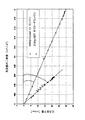
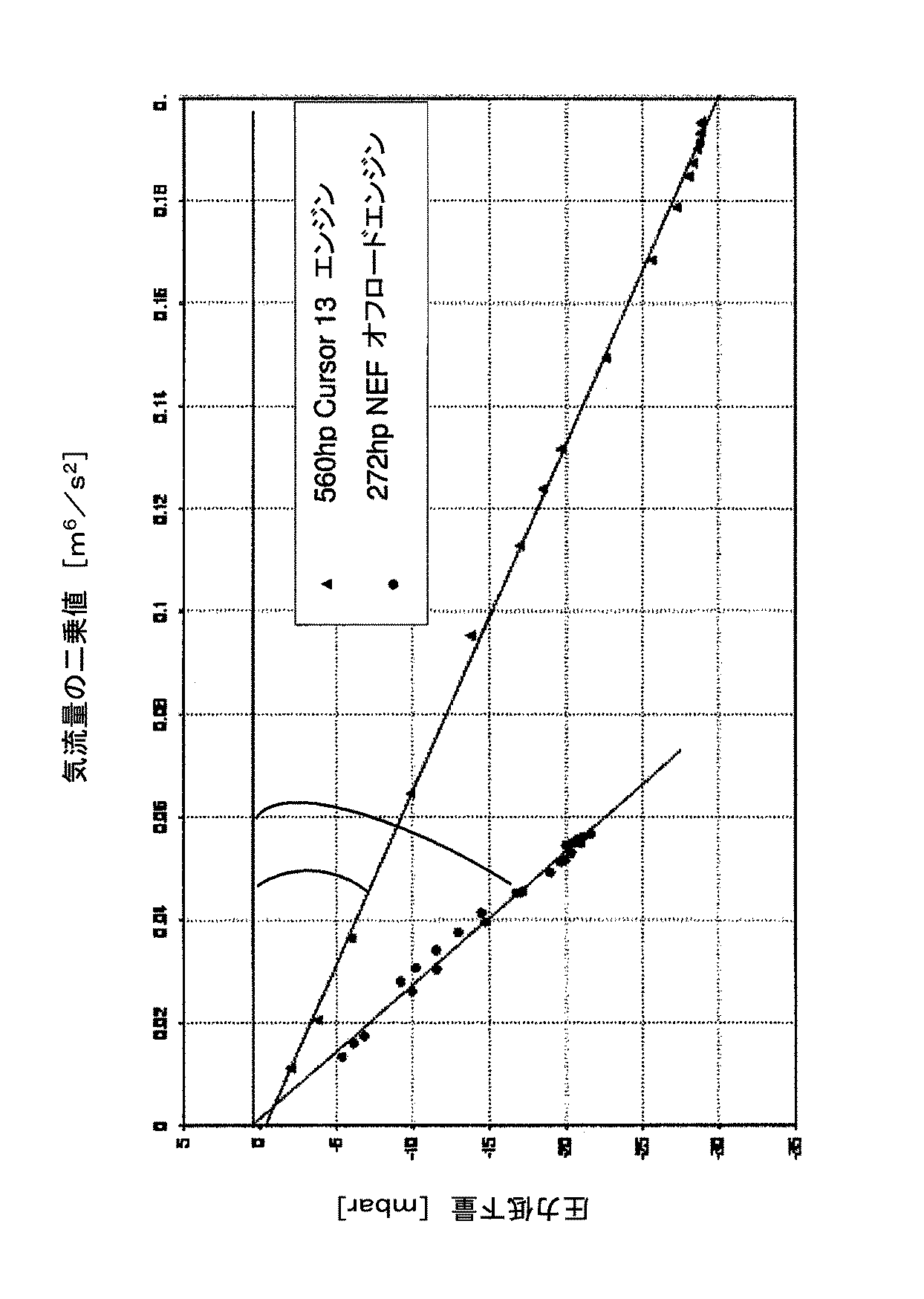
図2は、二つの異なるエンジンについてデータ対に対して上述した回帰直線を行なうことによりk因子を算出した結果の例をグラフとして示している。 FIG. 2 is a graph showing an example of the result of calculating the k factor by performing the above-described regression line on the data pair for two different engines.
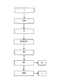
他方、図1は、本発明に係る方法の好適な実施形態をブロック図として示している。当該方法は、以下に列挙するステップを順に含んでいる。 On the other hand, FIG. 1 shows a preferred embodiment of the method according to the invention as a block diagram. The method includes the steps listed below in order.
(v)データ対の値を予備取得する。各データ対は、エアフィルタにおける圧力低下値(ia)と、当該圧力低下値に対応し、当該エアフィルタを通過する気流量の二乗値(ib)とを含んでいる。 (V) Preliminarily acquiring the value of the data pair. Each data pair includes a pressure drop value (ia) in the air filter and a square value (ib) of the air flow rate corresponding to the pressure drop value and passing through the air filter.
(iii)気流量あるいはその二乗値がとりうる範囲[(dV/dt)min,(dV/dt)max]あるいは[(dV/dt)2 min,(dV/dt)2 max]を隣り合う所定数の区間(0〜7)に分割する。 (Iii) The range [(dV / dt) min , (dV / dt) max ] or [(dV / dt) 2 min , (dV / dt) 2 max ] that can be taken by the air flow rate or its square value Divide into number intervals (0-7).
(iv)次いで、気流量の値(dV/dt)が属する区間に基づいて、データ対の値Δp、(dV/dt)2をグループ化し、各区間に関連付ける。 (Iv) Next, based on the section to which the air flow value (dV / dt) belongs, the data pair values Δp, (dV / dt) 2 are grouped and associated with each section.
(vi)少なくとも所定数の区間が少なくとも一つのデータ対と関連付けられるまで、さらなる演算を禁止する。 (Vi) Further operations are prohibited until at least a predetermined number of intervals are associated with at least one data pair.
(ik)上記複数のデータ対について回帰直線の角度係数kを算出する。 (Ik) The regression line angle coefficient k is calculated for the plurality of data pairs.
(iki)上記角度係数あるいはその関数を、少なくとも一つの閾値(好ましくは三つの閾値ThL、Th1、ThU)と比較する。これら三つの閾値は、ThL<Th1<ThUの関係にある。 (Iki) The angle coefficient or a function thereof is compared with at least one threshold (preferably three thresholds ThL, Th1, ThU). These three threshold values have a relationship of ThL <Th1 <ThU.
(ikii)以下に列挙する状態のいずれかを検出する。
・第一状態(ThL<k<Th1):フィルタが新品と良好な状態の少なくとも一方であると認められる。
・第二状態(Th1<k<ThU):フィルタが汚れているものの、危険な詰まり状態には達していないと認められる。
・第三状態(ThU<k):フィルタが危険な詰まり状態にあると認められる。
・第四状態(k<ThL):フィルタが新品であっても角度係数kが低すぎるため、以下のような深刻な危険状態であると認められる。
・フィルタカートリッジが装着されていない。
・誤ったフィルタカートリッジが装着されている。
・吸気漏れが生じている。
(Ikii) Any of the states listed below is detected.
First state (ThL <k <Th1): It is recognized that the filter is at least one of a new state and a good state.
Second state (Th1 <k <ThU): Although the filter is dirty, it is recognized that a dangerous clogging state has not been reached.
Third state (ThU <k): It is recognized that the filter is in a dangerously clogged state.
Fourth state (k <ThL): Since the angle coefficient k is too low even if the filter is new, it is recognized that the following dangerous state is present.
• The filter cartridge is not installed.
• The wrong filter cartridge is installed.
・ Intake leakage has occurred.
(ikiii)角度係数kが突然第二状態か第三状態から第四状態へ移行した場合、改造行為を示す第五状態を検出する。 (Ikiii) When the angle coefficient k suddenly shifts from the second state or the third state to the fourth state, the fifth state indicating the remodeling action is detected.
(ix)上記の第二状態が認められた場合、「次の機会にエアフィルタを交換すべき」旨を意味するエラーメッセージが車両のダッシュボードに表示される。 (Ix) When the second state is recognized, an error message indicating that “the air filter should be replaced at the next opportunity” is displayed on the dashboard of the vehicle.
(x)上記の第三状態、第四状態、第五状態のいずれかが認められた場合、深刻なエラーを示すメッセージが車両のダッシュボードに表示され、エンジンがリカバリモード(出力、トルク、速度などを制限)に切り替えられる。 (X) If any of the third, fourth, or fifth states is recognized, a serious error message is displayed on the vehicle dashboard and the engine is in recovery mode (output, torque, speed). Etc.).
本発明は、コンピュータプログラムとして有利に実現されうる。当該コンピュータプログラムは、コンピュータ上で実行されることによって上記の方法における少なくとも一つのステップを実行するプログラムコード手段を備えている。したがって、そのようなコンピュータプログラム、およびコンピュータ上で実行されることによって上記の方法における少なくとも一つのステップを実行するプログラムコード手段を備えるコンピュータが読み取り可能な媒体も特許権の範囲内である。 The present invention can be advantageously realized as a computer program. The computer program comprises program code means for executing at least one step in the above method by being executed on a computer. Accordingly, a computer readable medium comprising such a computer program and program code means for executing at least one step in the above method when executed on the computer is also within the scope of the patent.
好適な実施形態を開示する本明細書と添付の図面を考慮した当業者にとって、本発明の多くの変更、修正、変形、他の用途や応用が明らかである。本発明は、その範囲を逸脱しない当該変更、修正、変形、他の用途や応用に及ぶ。 Many alterations, modifications, variations and other uses and applications of the invention will be apparent to those skilled in the art from consideration of the present specification and the accompanying drawings disclosing preferred embodiments. The present invention extends to such changes, modifications, variations, and other uses and applications that do not depart from its scope.
当業者ならば上記の記載の教示に基づいて発明を実施可能であるため、より詳細な説明は行なわない。 Those skilled in the art will be able to practice the invention based on the teachings described above, and therefore will not be described in more detail.
Claims (16)
前記エアフィルタにおける圧力低下値(ia)と、当該圧力低下値に対応し、当該エアフィルタを通過する気流量の二乗値(ib)とをそれぞれ含んでいる複数のデータ対について回帰直線を計算し、当該回帰直線における角度係数(k)を取得するステップ(ik)と、
前記角度係数(k)またはその関数(f(k))を、少なくとも一つの閾値((ThL、Th1、ThU)、(kMinおよびkMax)、[(dV/dt)min,(dV/dt)max])と比較し(iki)、前記エアフィルタの動作状態を検出するステップ(ikii)と、
を含んでいる、
方法。 In particular, a method for detecting the state of an air filter in a combustion engine,
A regression line is calculated for a plurality of data pairs each including a pressure drop value (ia) in the air filter and a square value (ib) of the air flow rate corresponding to the pressure drop value and passing through the air filter. Obtaining an angle coefficient (k) in the regression line (ik);
The angle coefficient (k) or a function thereof (f (k)) is converted into at least one threshold ((ThL, Th1, ThU), (k Min and k Max ), [(dV / dt) min , (dV / dt). ) Max ]) (iki) and detecting the operating state of the air filter (ikii);
Including,
Method.
請求項1に記載の方法。 When the angle coefficient (k) or a function thereof (f (k)) exceeds a high threshold (ThU) (k or k (f)> ThU), the air filter is clogged.
The method of claim 1.
請求項1に記載の方法。 If the angle factor (k) or a function thereof (f (k)) is below a low threshold (ThL) (k or k (f) <ThU), a modification of the air filter, the absence of the air filter, or Intake pipe leak is observed,
The method of claim 1.
請求項1に記載の方法。
・第一状態(ThL<k<Th1):フィルタが新品と良好な状態の少なくとも一方であると認められる。
・第二状態(Th1<k<ThU):フィルタが汚れているものの、危険な詰まり状態には達していないと認められる。
・第三状態(ThU<k):フィルタが危険な詰まり状態にあると認められる。
・第四状態(k<ThL):フィルタが新品であっても角度係数kが低すぎるため、以下のような深刻な危険状態であると認められる。
・フィルタカートリッジが装着されていない。
・誤ったフィルタカートリッジが装着されている。
・吸気漏れが生じている。 The angular coefficient (k) or a function thereof (f (k)) is compared with at least three thresholds (ThL <Th1 <ThU) to detect at least four states listed below:
The method of claim 1.
First state (ThL <k <Th1): It is recognized that the filter is at least one of a new state and a good state.
Second state (Th1 <k <ThU): Although the filter is dirty, it is recognized that a dangerous clogging state has not been reached.
Third state (ThU <k): It is recognized that the filter is in a dangerously clogged state.
Fourth state (k <ThL): Since the angle coefficient k is too low even if the filter is new, it is recognized that the following dangerous state is present.
• The filter cartridge is not installed.
• The wrong filter cartridge is installed.
・ Intake leakage has occurred.
請求項4に記載の方法。 Detecting the fifth state indicating the remodeling action when the angle coefficient (k) or a function thereof (f (k)) suddenly shifts from the second state or the third state to the fourth state (ikiii) With
The method of claim 4.
請求項4に記載の方法。 If the fourth state or the fifth state is detected, the engine is switched to a recovery mode to limit its output, torque, or speed (x);
The method of claim 4.
請求項1に記載の方法。 The function (f (k)) of the angular coefficient n (k) is a predetermined theoretical maximum air flow rate ((dV / dt) max ) theoretical pressure drop maximum value (Δp max ).
The method of claim 1.
(Δpmax)=k[(dV/dt)max]2
として得られる、
請求項7に記載の方法。 The theoretical maximum value of pressure drop (Δp max ) is
(Δp max ) = k [(dV / dt) max ] 2
As obtained,
The method of claim 7.
前記圧力低下は、前記エアクリーナの下流に配置された第一絶対圧センサにより流量検出に基づいて測定された第一絶対圧を、外気に触れるように配置された第二絶対圧センサにより測定された第二絶対圧から差し引くことにより取得される、
請求項1に記載の方法。 The pressure drop is obtained by a differential pressure sensor, or
The pressure drop was measured by a second absolute pressure sensor arranged so as to come into contact with the outside air, the first absolute pressure measured based on the flow rate detection by a first absolute pressure sensor arranged downstream of the air cleaner. Obtained by subtracting from the second absolute pressure,
The method of claim 1.
次いで、気流量の値(dV/dt)が属する区間に基づいて、データ対の値(Δp、(dV/dt)2)がグループ化され、各区間に関連付けられ(iv)、
前記角度係数(k)は、次式により算出される(ik)、
請求項1に記載の方法。
Then, based on the interval to which the airflow value (dV / dt) belongs, the data pair values (Δp, (dV / dt) 2 ) are grouped and associated with each interval (iv),
The angle coefficient (k) is calculated by the following equation (ik),
The method of claim 1.
少なくとも所定数の区間が少なくとも一つの前記データ対と関連付けられるまで、前記回帰直線の計算を禁止するステップ(vi)と、
を備えている、
請求項10に記載の方法。 Obtaining the data pair ((Δp, (dV / dt) 2 )) (v);
Prohibiting calculation of the regression line until at least a predetermined number of intervals are associated with at least one of the data pairs;
With
The method of claim 10.
前記エアフィルタにおける圧力低下値を取得する手段と、
前記圧力低下値に対応し、前記エアフィルタを通過する気流量を取得する手段と、
請求項1から11のいずれか一項に記載された全てのステップを遂行するように構成された手段(ECU)と、
を備えている、
装置。 In particular, a device for detecting the state of an air filter in a combustion engine,
Means for obtaining a pressure drop value in the air filter;
Means for obtaining an air flow rate corresponding to the pressure drop value and passing through the air filter;
Means (ECU) configured to perform all the steps according to any one of claims 1 to 11;
With
apparatus.
コンピュータプログラム。 Comprising computer program code means adapted to perform all the steps recited in claim 1 when executed on a computer,
Computer program.
コンピュータ上で実行されることにより、請求項1から11のいずれか一項に記載された全てのステップを遂行するように構成されたコンピュータプログラムコード手段を備えている、
媒体。 A medium on which a computer-readable program is recorded,
Comprising computer program code means adapted to perform all the steps recited in any one of claims 1 to 11 when executed on a computer;
Medium.
請求項12に記載のエアフィルタの状態を検出する装置と、
を備えている、
燃焼機関。 An air filter,
An apparatus for detecting the state of the air filter according to claim 12,
With
Combustion engine.
地上車両。 The combustion engine according to claim 15 is provided.
Ground vehicle.
Applications Claiming Priority (2)
| Application Number | Priority Date | Filing Date | Title |
|---|---|---|---|
| EP14174739.4A EP2960484B1 (en) | 2014-06-27 | 2014-06-27 | System for detecting an air filter condition, in particular for combustion engines |
| EP14174739.4 | 2014-06-27 |
Publications (2)
| Publication Number | Publication Date |
|---|---|
| JP2016011663A true JP2016011663A (en) | 2016-01-21 |
| JP6577765B2 JP6577765B2 (en) | 2019-09-18 |
Family
ID=51162443
Family Applications (1)
| Application Number | Title | Priority Date | Filing Date |
|---|---|---|---|
| JP2015128787A Active JP6577765B2 (en) | 2014-06-27 | 2015-06-26 | A system that detects the condition of an air filter, particularly in a combustion engine |
Country Status (9)
| Country | Link |
|---|---|
| US (1) | US10126203B2 (en) |
| EP (1) | EP2960484B1 (en) |
| JP (1) | JP6577765B2 (en) |
| CN (1) | CN105221307B (en) |
| AR (1) | AR105220A1 (en) |
| AU (1) | AU2015203505B2 (en) |
| BR (1) | BR102015015643B1 (en) |
| ES (1) | ES2686355T3 (en) |
| RU (1) | RU2693340C9 (en) |
Families Citing this family (14)
| Publication number | Priority date | Publication date | Assignee | Title |
|---|---|---|---|---|
| US10288019B2 (en) * | 2016-07-21 | 2019-05-14 | Ford Global Technologies, Llc | Secondary system and method for controlling an engine |
| US10487767B2 (en) * | 2017-03-17 | 2019-11-26 | Ford Global Technologies, Llc | Method and system for monitoring air filter condition |
| US10100790B1 (en) * | 2017-08-22 | 2018-10-16 | Ford Global Technologies, Llc | Diagnosing an air filter with an electric boosting device |
| SE1751508A1 (en) * | 2017-12-07 | 2019-06-08 | Scania Cv Ab | Method and system for diagnosing supply of air to an internal combustion engine of a vehicle |
| CH715698B1 (en) * | 2018-12-27 | 2024-08-15 | Fortest Europe Sagl | Absolute pressure drop pneumatic leakage measurement system, with differential compensation to a reference sample and method of measuring leakage at differential pressure drop of an object |
| CN112696255B (en) * | 2019-10-23 | 2025-04-15 | 罗伯特·博世有限公司 | A method for detecting the degree of filter clogging in an internal combustion engine |
| NL2024196B1 (en) * | 2019-11-08 | 2021-07-20 | Daf Trucks Nv | A monitoring system, method and vehicle comprising such a system, for detecting clogging through fouling of an air filter of an internal combustion engine. |
| CN112090478B (en) * | 2020-08-25 | 2022-06-17 | 辽宁科技大学 | A Fault Diagnosis Method for Crusher Based on Linear Regression |
| CN112065617B (en) * | 2020-09-08 | 2021-04-09 | 上海星融汽车科技有限公司 | Air filter state detection method and system and vehicle |
| CN114252274B (en) * | 2021-12-13 | 2024-07-16 | 中国船舶重工集团公司第七0三研究所 | On-line detection method for blockage of gas turbine inlet filter |
| CN114673614B (en) * | 2022-03-22 | 2023-07-18 | 潍柴动力股份有限公司 | Method, device and vehicle for determining working state of air filter |
| DE102022001357A1 (en) | 2022-04-20 | 2023-10-26 | W.O.M. World Of Medicine Gmbh | Insufflator with device for recording the filter occupancy |
| CN114934852A (en) * | 2022-04-29 | 2022-08-23 | 潍柴动力股份有限公司 | Filter element cleanliness estimation method and device based on exhaust oxygen concentration |
| CN117267021A (en) * | 2022-06-13 | 2023-12-22 | 北汽福田汽车股份有限公司 | Air filter processing methods, devices and vehicles |
Citations (9)
| Publication number | Priority date | Publication date | Assignee | Title |
|---|---|---|---|---|
| EP0264818A2 (en) * | 1986-10-15 | 1988-04-27 | Sumitomo Electric Industries Limited | Manufacturing method for a plastics optical fiber |
| JPH07189706A (en) * | 1993-12-27 | 1995-07-28 | Mazda Motor Corp | Engine intake system |
| JPH1019775A (en) * | 1996-07-03 | 1998-01-23 | Denso Corp | Fuel property determination device, fuel injection amount control device, fuel filter clogging prediction device, clogging temperature estimation device, and fuel filter heater control device |
| JP2004019455A (en) * | 2002-06-12 | 2004-01-22 | Denso Corp | Device for detecting clogging of air cleaner for internal combustion engine |
| JP2006257363A (en) * | 2005-03-18 | 2006-09-28 | Nippon Oil Corp | Apparatus and method for evaluating diesel fuel for diesel vehicles |
| JP2007536073A (en) * | 2004-05-06 | 2007-12-13 | キャリア コーポレイション | Air filter condition detection and prediction technology |
| JP2009121464A (en) * | 2007-11-13 | 2009-06-04 | Volvo Construction Equipment Ab | Apparatus and method for controlling engine speed for excavator |
| EP2604818A1 (en) * | 2011-12-15 | 2013-06-19 | Peugeot Citroën Automobiles Sa | Method and device for determining the criticality of the clogging of a particle filter with respect to the power of an internal combustion engine |
| JP2013127572A (en) * | 2011-12-19 | 2013-06-27 | Sanyo Electric Co Ltd | Projection type video display device |
Family Cites Families (17)
| Publication number | Priority date | Publication date | Assignee | Title |
|---|---|---|---|---|
| SU1333812A1 (en) * | 1985-07-12 | 1987-08-30 | Предприятие П/Я Г-4385 | Apparatus for comparable tests of air cleaners of i.c.engines |
| SU1467235A1 (en) * | 1987-08-18 | 1989-03-23 | Камское объединение по производству большегрузных автомобилей | Air cleaner clogging indicator for ic-engine |
| JP2621264B2 (en) * | 1987-12-18 | 1997-06-18 | 株式会社デンソー | ▲ Ro ▼ Detector for clogging of excess element |
| US5036698A (en) * | 1990-05-04 | 1991-08-06 | Allied-Signal Inc. | Method and apparatus for predicting life of air filter cartridges |
| DE10260784A1 (en) * | 2002-12-23 | 2004-07-01 | Daimlerchrysler Ag | Method for monitoring the degree of contamination of a filter device |
| JP2005016459A (en) * | 2003-06-27 | 2005-01-20 | Toyota Motor Corp | Control device for an internal combustion engine with a supercharger |
| US20110146246A1 (en) * | 2009-12-22 | 2011-06-23 | Caterpillar Inc. | Regeneration assist transition period |
| US8397500B2 (en) * | 2010-02-12 | 2013-03-19 | GM Global Technology Operations LLC | System and method for estimating airflow restriction of an engine air filter |
| US8626456B2 (en) * | 2010-03-23 | 2014-01-07 | GM Global Technology Operations LLC | Methods for determining a remaining useful life of an air filter |
| WO2012053097A1 (en) * | 2010-10-22 | 2012-04-26 | トヨタ自動車株式会社 | Filter failure detection device for internal combustion engine |
| KR20120062574A (en) * | 2010-12-06 | 2012-06-14 | 현대자동차주식회사 | System for checking filter of air cleaner for automobiles |
| US8613792B2 (en) * | 2011-06-20 | 2013-12-24 | Honeywell International Inc. | Method and systems for setting an air filter change threshold value in an HVAC system |
| EP2620202B1 (en) * | 2012-01-30 | 2014-10-29 | ABB Oy | Method and apparatus for monitoring air filter condition |
| US9183723B2 (en) * | 2012-01-31 | 2015-11-10 | Cleanalert, Llc | Filter clog detection and notification system |
| US9366171B2 (en) * | 2014-01-13 | 2016-06-14 | GM Global Technology Operations LLC | Method for determining an estimated amount of soot accumulated in a particulate filter of an exhaust gas after-treatment system |
| US9664095B2 (en) * | 2014-04-01 | 2017-05-30 | Ford Global Technologies, Llc | Method and system for leak detection at a particulate filter |
| US9664126B2 (en) * | 2014-06-09 | 2017-05-30 | Ford Global Technologies, Llc | System and methods for engine-off natural vacuum tests |
-
2014
- 2014-06-27 EP EP14174739.4A patent/EP2960484B1/en active Active
- 2014-06-27 ES ES14174739.4T patent/ES2686355T3/en active Active
-
2015
- 2015-06-24 AU AU2015203505A patent/AU2015203505B2/en active Active
- 2015-06-25 US US14/749,946 patent/US10126203B2/en active Active
- 2015-06-26 RU RU2015125489A patent/RU2693340C9/en active
- 2015-06-26 AR ARP150102055A patent/AR105220A1/en unknown
- 2015-06-26 JP JP2015128787A patent/JP6577765B2/en active Active
- 2015-06-26 BR BR102015015643-0A patent/BR102015015643B1/en active IP Right Grant
- 2015-06-29 CN CN201510370119.2A patent/CN105221307B/en active Active
Patent Citations (9)
| Publication number | Priority date | Publication date | Assignee | Title |
|---|---|---|---|---|
| EP0264818A2 (en) * | 1986-10-15 | 1988-04-27 | Sumitomo Electric Industries Limited | Manufacturing method for a plastics optical fiber |
| JPH07189706A (en) * | 1993-12-27 | 1995-07-28 | Mazda Motor Corp | Engine intake system |
| JPH1019775A (en) * | 1996-07-03 | 1998-01-23 | Denso Corp | Fuel property determination device, fuel injection amount control device, fuel filter clogging prediction device, clogging temperature estimation device, and fuel filter heater control device |
| JP2004019455A (en) * | 2002-06-12 | 2004-01-22 | Denso Corp | Device for detecting clogging of air cleaner for internal combustion engine |
| JP2007536073A (en) * | 2004-05-06 | 2007-12-13 | キャリア コーポレイション | Air filter condition detection and prediction technology |
| JP2006257363A (en) * | 2005-03-18 | 2006-09-28 | Nippon Oil Corp | Apparatus and method for evaluating diesel fuel for diesel vehicles |
| JP2009121464A (en) * | 2007-11-13 | 2009-06-04 | Volvo Construction Equipment Ab | Apparatus and method for controlling engine speed for excavator |
| EP2604818A1 (en) * | 2011-12-15 | 2013-06-19 | Peugeot Citroën Automobiles Sa | Method and device for determining the criticality of the clogging of a particle filter with respect to the power of an internal combustion engine |
| JP2013127572A (en) * | 2011-12-19 | 2013-06-27 | Sanyo Electric Co Ltd | Projection type video display device |
Also Published As
| Publication number | Publication date |
|---|---|
| CN105221307B (en) | 2019-06-04 |
| EP2960484A1 (en) | 2015-12-30 |
| AU2015203505A1 (en) | 2016-01-21 |
| AU2015203505B2 (en) | 2019-12-12 |
| EP2960484B1 (en) | 2018-06-13 |
| BR102015015643A2 (en) | 2017-11-07 |
| BR102015015643B1 (en) | 2022-05-03 |
| RU2693340C2 (en) | 2019-07-02 |
| US10126203B2 (en) | 2018-11-13 |
| JP6577765B2 (en) | 2019-09-18 |
| RU2693340C9 (en) | 2019-12-19 |
| US20160018288A1 (en) | 2016-01-21 |
| RU2015125489A (en) | 2017-01-10 |
| RU2015125489A3 (en) | 2018-12-10 |
| ES2686355T3 (en) | 2018-10-17 |
| AR105220A1 (en) | 2017-09-20 |
| CN105221307A (en) | 2016-01-06 |
Similar Documents
| Publication | Publication Date | Title |
|---|---|---|
| JP6577765B2 (en) | A system that detects the condition of an air filter, particularly in a combustion engine | |
| CN107882618B (en) | Method for diagnosing pressure difference measurement | |
| DE102016209463B4 (en) | DIAGNOSTIC SYSTEM AND METHOD FOR PARTICULATE SENSOR | |
| CN107956543B (en) | Diesel engine particle catcher fault detection system and detection method thereof | |
| KR102166580B1 (en) | Method and apparatus for checking the feasibility of function of crankcase ventilation system | |
| CN104838106B (en) | The condition diagnosing of particulate filter | |
| US11098630B2 (en) | Method and computer program product for diagnosing a particle filter | |
| CN105829874B (en) | Humidity measuring instrument | |
| JP5689947B2 (en) | Automatic operation method of measuring device for particle measurement in gas | |
| EP3061937A1 (en) | Abnormality determination system for an exhaust device | |
| JP3959038B2 (en) | Method for calculating atmospheric pressure based on the pressure in the intake line of an internal combustion engine | |
| JP2013524164A5 (en) | ||
| CN110831687A (en) | Method for evaluating the state of a particle filter and exhaust system for a motor vehicle | |
| JP4747156B2 (en) | Exhaust purification device diagnostic device | |
| KR20100014067A (en) | Method for fault localization and diagnosis in a fluidic installation | |
| CN116108366A (en) | A Fault Diagnosis Method for Lubricating Oil System of Aeroengine | |
| US7930876B2 (en) | Method and device for monitoring a particle filter in the exhaust line of an internal combustion engine | |
| US7637140B2 (en) | Method and device for detecting an incorrectly connected differential pressure sensor | |
| CN115163359A (en) | Monitoring method and monitoring system for engine air intake system | |
| CN104763503B (en) | Method for monitoring components in an exhaust duct of an internal combustion engine, device for implementing the method, computer program and computer program product | |
| EP3390789B1 (en) | Method and arrangement for correcting for error of particulate matter sensors | |
| SE1250440A1 (en) | Method for indicating the function of a pressure sensor, and a single indication device in connection with the method | |
| CN115950582A (en) | Correction method, device, medium and equipment of a differential pressure sensor | |
| WO2017035547A1 (en) | Method for detecting an unsealed location in a heat recovery system of an internal combustion engine | |
| JP6631786B2 (en) | Exhaust aftertreatment system |
Legal Events
| Date | Code | Title | Description |
|---|---|---|---|
| A521 | Request for written amendment filed |
Free format text: JAPANESE INTERMEDIATE CODE: A523 Effective date: 20160722 |
|
| A621 | Written request for application examination |
Free format text: JAPANESE INTERMEDIATE CODE: A621 Effective date: 20180515 |
|
| A977 | Report on retrieval |
Free format text: JAPANESE INTERMEDIATE CODE: A971007 Effective date: 20190221 |
|
| A131 | Notification of reasons for refusal |
Free format text: JAPANESE INTERMEDIATE CODE: A131 Effective date: 20190226 |
|
| A521 | Request for written amendment filed |
Free format text: JAPANESE INTERMEDIATE CODE: A523 Effective date: 20190521 |
|
| TRDD | Decision of grant or rejection written | ||
| A01 | Written decision to grant a patent or to grant a registration (utility model) |
Free format text: JAPANESE INTERMEDIATE CODE: A01 Effective date: 20190806 |
|
| A61 | First payment of annual fees (during grant procedure) |
Free format text: JAPANESE INTERMEDIATE CODE: A61 Effective date: 20190823 |
|
| R150 | Certificate of patent or registration of utility model |
Ref document number: 6577765 Country of ref document: JP Free format text: JAPANESE INTERMEDIATE CODE: R150 |
|
| R250 | Receipt of annual fees |
Free format text: JAPANESE INTERMEDIATE CODE: R250 |
|
| R250 | Receipt of annual fees |
Free format text: JAPANESE INTERMEDIATE CODE: R250 |
|
| R250 | Receipt of annual fees |
Free format text: JAPANESE INTERMEDIATE CODE: R250 |
|
| R250 | Receipt of annual fees |
Free format text: JAPANESE INTERMEDIATE CODE: R250 |