JP2016009707A - Cooling fan device - Google Patents
Cooling fan device Download PDFInfo
- Publication number
- JP2016009707A JP2016009707A JP2014128135A JP2014128135A JP2016009707A JP 2016009707 A JP2016009707 A JP 2016009707A JP 2014128135 A JP2014128135 A JP 2014128135A JP 2014128135 A JP2014128135 A JP 2014128135A JP 2016009707 A JP2016009707 A JP 2016009707A
- Authority
- JP
- Japan
- Prior art keywords
- drive shaft
- detection sensor
- fan motor
- dustproof filter
- cooling fan
- Prior art date
- Legal status (The legal status is an assumption and is not a legal conclusion. Google has not performed a legal analysis and makes no representation as to the accuracy of the status listed.)
- Pending
Links
Images
Landscapes
- Filtering Of Dispersed Particles In Gases (AREA)
- Cooling Or The Like Of Electrical Apparatus (AREA)
Abstract
Description
この発明は、内部に発熱体を収容する筐体の開口部から外部空気を吸入して筐体内部を冷却する冷却ファン装置に関するものである。 The present invention relates to a cooling fan device that cools the inside of a housing by sucking outside air from an opening of the housing that houses a heating element.
従来の冷却ファン装置では、防塵フィルタが冷却ファンの動作により形成される風の流路を横断して覆うように設置されており、BMC(ベースボードマネージメントコントローラ)が防塵フィルタの目詰まり状態を検知すると、モータを動作させて防塵フィルタを巻き取り、防塵フィルタの未使用部分を風の流路に位置させていた(例えば、特許文献1参照)。 In the conventional cooling fan device, the dustproof filter is installed so as to cover the air flow path formed by the operation of the cooling fan, and the BMC (base board management controller) detects the clogged state of the dustproof filter. Then, the dustproof filter was wound up by operating the motor, and the unused portion of the dustproof filter was positioned in the wind passage (for example, see Patent Document 1).
しかしながら、従来の冷却ファン装置では、防塵フィルタを巻き取るための専用のモータが必要となり、コストが高騰するという課題があった。 However, the conventional cooling fan device requires a dedicated motor for winding up the dustproof filter, and there is a problem that the cost increases.
この発明は、上記のような問題点を解決するためになされたもので、ファンモータの回転トルクを利用して防塵フィルタの巻き取りを行うようにして、防塵フィルタの巻き取り専用モータを不要とし、低コスト化を図ることができる冷却ファン装置を得ることを目的としている。 The present invention has been made to solve the above-described problems. The dust-proof filter is wound by using the rotational torque of the fan motor, so that a dust-dedicated filter wind-up motor is not required. An object of the present invention is to obtain a cooling fan device capable of reducing the cost.
この発明による冷却ファン装置は、開口部を有する筐体と、互いに軸方向を平行として、上記開口部を挟んで配置された従動軸および駆動軸と、上記従動軸にロール状に巻かれ、上記従動軸から繰り出されて上記開口部を塞ぐように横断して上記駆動軸に巻き取られる防塵フィルタと、上記開口部を横断する上記防塵フィルタにブレードを対向させて上記筐体内に配設された冷却ファンと、上記防塵フィルタの目詰まりを検出する目詰まり検出センサ部と、上記冷却ファンのファンモータの回転トルクを上記駆動軸に伝達するトルク伝達部と、上記目詰まり検出センサ部の検出信号に基づいて上記防塵フィルタが目詰まりとなったと判定すると、上記ファンモータの回転トルクを上記トルク伝達部を介して上記駆動軸に伝達して上記駆動軸を駆動させ、上記防塵フィルタを上記駆動軸に巻き取らせる制御部と、を備える。 The cooling fan device according to the present invention includes a housing having an opening, a driven shaft and a drive shaft that are arranged with the opening parallel to each other with the axial direction parallel to each other, and wound around the driven shaft in a roll shape. A dust-proof filter that is drawn out from the driven shaft and traversed so as to close the opening and wound around the drive shaft, and a blade is disposed in the housing with the blade facing the dust-proof filter that traverses the opening. A cooling fan, a clogging detection sensor unit that detects clogging of the dustproof filter, a torque transmission unit that transmits the rotational torque of the fan motor of the cooling fan to the drive shaft, and a detection signal of the clogging detection sensor unit If the dust filter is determined to be clogged based on the rotational speed of the fan motor, the rotational torque of the fan motor is transmitted to the drive shaft via the torque transmission portion, and the drive shaft is It is moving, and a control unit to assume winding the dust filter to the drive shaft.
この発明によれば、ファンモータの回転トルクをトルク伝達部を介して駆動軸に伝達して駆動軸を駆動させ、防塵フィルタを駆動軸に巻き取らせているので、防塵フィルタの巻き取り専用モータが不要となり、低コスト化を図ることができる。 According to the present invention, the rotational torque of the fan motor is transmitted to the drive shaft via the torque transmission unit to drive the drive shaft, and the dust filter is wound around the drive shaft. Can be eliminated, and the cost can be reduced.
実施の形態1.
図1はこの発明の実施の形態1における冷却ファン装置を示す構成図、図2はこの発明の実施の形態1における冷却ファン装置の動作を説明するフローチャートである。
Embodiment 1 FIG.
FIG. 1 is a block diagram showing a cooling fan device according to Embodiment 1 of the present invention, and FIG. 2 is a flowchart for explaining the operation of the cooling fan device according to Embodiment 1 of the present invention.
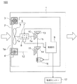
図1において、冷却ファン装置100は、発熱体(図示せず)が収容される筐体1と、筐体1の開口部1aを覆うように配置され、開口部1aから筐体1の内部に吸入される外部空気に含まれる塵を除去する防塵フィルタ2と、ブレード6を防塵フィルタ2と対向させて筐体1内に設置され、開口部1aから外部空気を吸入して筐体1の内部を冷却する冷却ファン5と、冷却ファン5のファンモータ7の回転数を検出する目詰まり検出部としても回転検出センサ8と、ファンモータ7の回転トルクを後述する駆動軸4に伝達するトルク伝達部と、回転検出センサ8の検出信号に基づいて防塵フィルタ2の目詰まりを判定し、防塵フィルタ2が目詰まりとなったと判定すると、トルク伝達部を介してファンモータ7の回転トルクを駆動軸4に伝達し、駆動軸4を駆動させて防塵フィルタ2を駆動軸4に巻き取らせる制御部9と、を備えている。
In FIG. 1, a
防塵フィルタ2は、一定の幅で連続するシート状に作製されている。防塵フィルタ2は、開口部1aの一側に軸周りに回転可能に配置された従動軸3にロール状に巻かれ、従動軸3から繰り出され、開口部1aを塞ぐように横断して、開口部1aを挟んで従動軸3と平行に、かつ軸周りに回転可能に配置された駆動軸4に巻き取られている。
The
冷却ファン5は、ファンモータ7のモータ軸7aの一端に固着されたブレード6を、開口部1aを覆う防塵フィルタ2に向けて筐体1内に配設されている。そして、第1ギア10がファンモータ7のモータ軸7aの他端に固着されている。また、第2ギア11が、駆動軸4に回転トルク伝達可能に連結されたトルク伝達軸12に固着されている。
The
第1連結ギア13と第2連結ギア14が、連結軸15に連結軸15の長さ方向に離間して固着されている。連結軸15は、第1連結ギア13と第2連結ギア14がそれぞれ第1ギア10と第2ギア11に歯合する作動位置と、第1連結ギア13と第2連結ギア14がそれぞれ第1ギア10と第2ギア11から離間して歯合解除される待避位置と、の間を往復移動可能に配置されている。さらに、ソレノイド16が、励磁されて、連結軸15を作動位置に移動させ、非励磁となって、連結軸15を待避位置に戻すように構成されている。
The first connecting
ここで、第1および第2ギア10,11、トルク伝達軸12、第1および第2連結ギア13,14、連結軸15およびソレノイド16によりトルク伝達部が構成されている。
Here, the first and
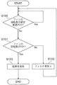
つぎに、冷却ファン装置100の動作について図2を参照しつつ説明する。なお、図2中、便宜上ステップ100〜ステップ103をS100〜S103としている。
Next, the operation of the
まず、制御装置9がファンモータ7に運転指令を送信し、ファンモータ7が運転される。これにより、ブレード6が回転駆動され、外部空気が開口部1aから防塵フィルタ2を通って筐体1内に吸入される。このとき、外部空気内に含まれる塵が防塵フィルタ2に取り込まれ、筐体1内への侵入が阻止される。筐体1内に吸入された外部空気は、図1中矢印で示されるように、筐体1内に収容されている発熱体(図示せず)の熱を吸熱し、筐体1外に排出される。
First, the control device 9 transmits an operation command to the
ファンモータ7の回転数は回転検出センサ8により検出され、制御部9に送信される。制御部9は、回転検出センサ8の検出信号に基づいて、ファンモータ7の回転数が設定範囲内に入っているか否かを判定する(ステップ100)。そして、ファンモータ7の回転数が設定範囲内に入っていると、防塵フィルタ2は目詰まり状態ではないと判断し、ステップ100に戻る。
The rotation speed of the
ステップ100において、ファンモータ7の回転数が設定範囲内に入っていないと、ステップ101に移行し、回転検出センサ8の検出信号に基づいて、ファンモータ7の回転数が0であるか否かを判定する。そして、ファンモータ7の回転数が0でないと、防塵フィルタ2は目詰まり状態であると判定し、ステップ102に移行する。
If the rotational speed of the
ステップ102では、制御部9がソレノイド16に励磁指令を送信し、ソレノイド16が励磁される。これにより、連結軸15が待避位置から作動位置に移動し、第1連結ギア13が第1ギア10に歯合し、第2連結ギア14が第2ギア11に歯合する。そこで、ファンモータ7の回転トルクが、モータ軸7aから第1ギア10、第1連結ギア13、連結軸15、第2連結ギア14、第2ギア11およびトルク伝達軸12を介して駆動軸4に伝達される。これにより、駆動軸4が回転され、防塵フィルタ2が駆動軸4に巻き取られる。そして、設定された時間経過後に、制御部9がソレノイド16に非励磁指令を送信し、ステップ100に戻る。そこで、ソレノイド16は非励磁状態となり、連結軸15が待避位置に戻り、第1および第2ギア10,11と第1および第2連結ギア13,14との歯合が解除される。そこで、駆動軸4の回転が停止し、従動軸3から繰り出された未使用領域の防塵フィルタ2が開口部1aを塞ぎ、開口部1aから吸入される外部空気内に含まれる塵が防塵フィルタ2に取り込まれる。
In
ステップ101において、ファンモータ7の回転数が0であると、ファンモータ7が故障したと判定し、ステップ103に移行する。ステップ103では、制御部9は、外部の監視センター17にファンモータ7の故障を報知するとともに、ファンモータ7に運転停止指令を送信し、冷却ファン装置100の動作を停止させる。監視センター17では、ファンモータ7の故障発生の報知を受け、保守作業員が現地に急行し、ファンモータ7の修理・交換を行うことになる。
If the rotation speed of the
この実施の形態1によれば、防塵フィルタ2の目詰まりを検知して、開口部1aを覆っている防塵フィルタ2の部分を自動的に未使用部分に更新しているので、作業員による、開口部1aを覆っている防塵フィルタ2の部分を自動的に未使用部分に更新する作業が不要となる。そこで、機械室レスエレベータのように、防塵フィルタ2の更新作業がし難い場所に設置された制御盤の冷却に冷却ファン装置100を適用する場合には、特に効果的である。
According to the first embodiment, the clogging of the
また、ファンモータ7の回転トルクを利用して駆動軸4を回転駆動し、防塵フィルタ2を駆動軸4に巻き取っているので、駆動軸4を駆動するための専用のモータが不要となり、冷却ファン装置100の低コスト化が図られる。
Further, since the
また、ファンモータ7の回転数を検出する回転検出センサ8の検出信号に基づいて、ファンモータ7の回転数が0となったときに、ファンモータ7の故障発生を監視センター17に報知するとともに、ファンモータ7の運転を停止している。そこで、ファンモータ8の修理・交換を迅速に行えるとともに、故障したファンモータ8に通電し続けることによる二次災害の発生を防止することができる。さらに、回転検出センサ8を目詰まり検出部としているので、目詰まり検出部としての温度センサや風量センサを新たに設ける必要がなく、部品点数が削減でき、低コスト化が図られる。
Further, based on the detection signal of the rotation detection sensor 8 that detects the rotation speed of the
なお、上記実施の形態1では、目詰まり検出センサ部としてファンモータ7の回転数を検出する回転検出センサ8を用いているが、目詰まり検出センサ部は回転検出センサ8に限定されず、筐体1内に設置される風量センサや温度センサでもよい。例えば、風量センサを用いる場合には、風量センサの検出信号に基づいて風量が設定範囲内か否かを判定すればよい。また、温度センサを用いる場合には、温度センサの検出信号に基づいて筐体1内の温度が設定範囲内か否かを判定すればよい。
In the first embodiment, the rotation detection sensor 8 that detects the rotation speed of the
1 筐体、1a 開口部、2 防塵フィルタ、3 従動軸、4 駆動軸、5 冷却ファン、6 ブレード、7 ファンモータ、8 回転検出センサ(目詰まり検出部)、9 制御部、10 第1ギア(トルク伝達部)、11 第2ギア(トルク伝達部)、12 トルク伝達軸(トルク伝達部)、13 第1連結ギア(トルク伝達部)、14 第2連結ギア(トルク伝達部)、15 連結軸(トルク伝達部)、16 ソレノイド(トルク伝達部)、17 監視センター。 DESCRIPTION OF SYMBOLS 1 Housing | casing, 1a opening part, 2 dustproof filter, 3 driven shaft, 4 drive shaft, 5 cooling fan, 6 blade, 7 fan motor, 8 rotation detection sensor (clogging detection part), 9 control part, 10 1st gear (Torque transmission unit), 11 second gear (torque transmission unit), 12 torque transmission shaft (torque transmission unit), 13 first connection gear (torque transmission unit), 14 second connection gear (torque transmission unit), 15 connection Shaft (torque transmission part), 16 Solenoid (torque transmission part), 17 Monitoring center.
Claims (3)
互いに軸方向を平行として、上記開口部を挟んで配置された従動軸および駆動軸と、
上記従動軸にロール状に巻かれ、上記従動軸から繰り出されて上記開口部を塞ぐように横断して上記駆動軸に巻き取られる防塵フィルタと、
上記開口部を横断する上記防塵フィルタにブレードを対向させて上記筐体内に配設された冷却ファンと、
上記防塵フィルタの目詰まりを検出する目詰まり検出センサ部と、
上記冷却ファンのファンモータの回転トルクを上記駆動軸に伝達するトルク伝達部と、
上記目詰まり検出センサ部の検出信号に基づいて上記防塵フィルタが目詰まりとなったと判定すると、上記ファンモータの回転トルクを上記トルク伝達部を介して上記駆動軸に伝達して上記駆動軸を駆動させ、上記防塵フィルタを上記駆動軸に巻き取らせる制御部と、を備える冷却ファン装置。 A housing having an opening;
A driven shaft and a drive shaft, which are arranged parallel to each other and sandwiching the opening,
A dust-proof filter wound around the driven shaft in a roll shape, drawn out from the driven shaft and traversed so as to close the opening, and wound around the drive shaft;
A cooling fan disposed in the casing with a blade opposed to the dustproof filter traversing the opening;
A clogging detection sensor for detecting clogging of the dustproof filter;
A torque transmission unit for transmitting the rotational torque of the fan motor of the cooling fan to the drive shaft;
When it is determined that the dustproof filter is clogged based on the detection signal of the clogging detection sensor unit, the rotational torque of the fan motor is transmitted to the drive shaft via the torque transmission unit to drive the drive shaft. And a control unit that winds the dustproof filter around the drive shaft.
上記制御部は、上記回転検出センサの検出信号に基づいて上記ファンモータが回転していないと判定すると、上記冷却ファンの故障を監視センターに報知するように構成されている請求項1記載の冷却ファン装置。 A rotation detection sensor for detecting the rotation speed of the fan motor;
2. The cooling according to claim 1, wherein the control unit is configured to notify a monitoring center of a failure of the cooling fan when determining that the fan motor is not rotating based on a detection signal of the rotation detection sensor. Fan device.
上記制御部は、上記回転検出センサの検出信号に基づいて、上記ファンモータの回転数が設定範囲外となった時に、上記防塵フィルタが目詰まりとなったと判定するように構成されている請求項2記載の冷却ファン装置。 The rotation detection sensor also serves as the clogging detection sensor unit,
The said control part is comprised so that it may determine with the said dust-proof filter becoming clogged when the rotation speed of the said fan motor becomes out of a setting range based on the detection signal of the said rotation detection sensor. 2. The cooling fan device according to 2.
Priority Applications (1)
| Application Number | Priority Date | Filing Date | Title |
|---|---|---|---|
| JP2014128135A JP2016009707A (en) | 2014-06-23 | 2014-06-23 | Cooling fan device |
Applications Claiming Priority (1)
| Application Number | Priority Date | Filing Date | Title |
|---|---|---|---|
| JP2014128135A JP2016009707A (en) | 2014-06-23 | 2014-06-23 | Cooling fan device |
Publications (1)
| Publication Number | Publication Date |
|---|---|
| JP2016009707A true JP2016009707A (en) | 2016-01-18 |
Family
ID=55227101
Family Applications (1)
| Application Number | Title | Priority Date | Filing Date |
|---|---|---|---|
| JP2014128135A Pending JP2016009707A (en) | 2014-06-23 | 2014-06-23 | Cooling fan device |
Country Status (1)
| Country | Link |
|---|---|
| JP (1) | JP2016009707A (en) |
-
2014
- 2014-06-23 JP JP2014128135A patent/JP2016009707A/en active Pending
Similar Documents
| Publication | Publication Date | Title |
|---|---|---|
| KR101400613B1 (en) | Air-conditioning apparatus and support system of the same | |
| JP5287620B2 (en) | Air purification device | |
| CN111821778B (en) | Air filter device for industrial machine | |
| CN101107482B (en) | Fan filter unit | |
| US10112218B2 (en) | Chamber cleaning apparatus and control method thereof | |
| CN105793562A (en) | Windmill drive device and windmill drive device unit | |
| JP6376507B2 (en) | Air conditioner | |
| JP2013010175A (en) | Driving device for grinder, and corresponding grinder | |
| WO2016197794A2 (en) | Dust-proof net replacement device, fan cover and cabinet | |
| CN110031230A (en) | A kind of ship machinery fault alarm detection device | |
| CN110761826A (en) | Safe and reliable tunnel ventilation device with vibration detection function | |
| JP2009208922A (en) | Elevator | |
| JP2016009707A (en) | Cooling fan device | |
| CN205048702U (en) | Filter screen automatic exchange device that special type air conditioning equipment used | |
| JP6309430B2 (en) | Retractable filter device | |
| JP6053614B2 (en) | Indoor ventilation system and control method thereof | |
| JP4984936B2 (en) | Heating cooker and heating cooking system equipped with the same | |
| CN110654787B (en) | Auger control device and method | |
| CN109268897B (en) | Dynamic oil net, smoke machine comprising same and control method | |
| JP5193791B2 (en) | Air conditioner | |
| JP2010259966A (en) | Filter unit | |
| JP6479290B1 (en) | Laser apparatus and laser processing machine | |
| JP5251526B2 (en) | Dust-proof filter clogging prevention device | |
| CN110785611A (en) | Air conditioner | |
| CN119052428A (en) | Computer safety monitoring device and early warning method |