JP2016007789A - Ink jet printer and control method of the same - Google Patents
Ink jet printer and control method of the sameInfo
- Publication number
- JP2016007789A JP2016007789A JP2014129987A JP2014129987A JP2016007789A JP 2016007789 A JP2016007789 A JP 2016007789A JP 2014129987 A JP2014129987 A JP 2014129987A JP 2014129987 A JP2014129987 A JP 2014129987A JP 2016007789 A JP2016007789 A JP 2016007789A
- Authority
- JP
- Japan
- Prior art keywords
- ink
- discharge
- ejection
- operation mode
- mode
- Prior art date
- Legal status (The legal status is an assumption and is not a legal conclusion. Google has not performed a legal analysis and makes no representation as to the accuracy of the status listed.)
- Pending
Links
Images

Classifications
-
- B—PERFORMING OPERATIONS; TRANSPORTING
- B41—PRINTING; LINING MACHINES; TYPEWRITERS; STAMPS
- B41J—TYPEWRITERS; SELECTIVE PRINTING MECHANISMS, i.e. MECHANISMS PRINTING OTHERWISE THAN FROM A FORME; CORRECTION OF TYPOGRAPHICAL ERRORS
- B41J2/00—Typewriters or selective printing mechanisms characterised by the printing or marking process for which they are designed
- B41J2/005—Typewriters or selective printing mechanisms characterised by the printing or marking process for which they are designed characterised by bringing liquid or particles selectively into contact with a printing material
- B41J2/01—Ink jet
- B41J2/015—Ink jet characterised by the jet generation process
- B41J2/04—Ink jet characterised by the jet generation process generating single droplets or particles on demand
- B41J2/045—Ink jet characterised by the jet generation process generating single droplets or particles on demand by pressure, e.g. electromechanical transducers
- B41J2/04501—Control methods or devices therefor, e.g. driver circuits, control circuits
- B41J2/04551—Control methods or devices therefor, e.g. driver circuits, control circuits using several operating modes
-
- B—PERFORMING OPERATIONS; TRANSPORTING
- B41—PRINTING; LINING MACHINES; TYPEWRITERS; STAMPS
- B41J—TYPEWRITERS; SELECTIVE PRINTING MECHANISMS, i.e. MECHANISMS PRINTING OTHERWISE THAN FROM A FORME; CORRECTION OF TYPOGRAPHICAL ERRORS
- B41J2/00—Typewriters or selective printing mechanisms characterised by the printing or marking process for which they are designed
- B41J2/005—Typewriters or selective printing mechanisms characterised by the printing or marking process for which they are designed characterised by bringing liquid or particles selectively into contact with a printing material
- B41J2/01—Ink jet
- B41J2/015—Ink jet characterised by the jet generation process
- B41J2/04—Ink jet characterised by the jet generation process generating single droplets or particles on demand
- B41J2/045—Ink jet characterised by the jet generation process generating single droplets or particles on demand by pressure, e.g. electromechanical transducers
- B41J2/04501—Control methods or devices therefor, e.g. driver circuits, control circuits
- B41J2/04581—Control methods or devices therefor, e.g. driver circuits, control circuits controlling heads based on piezoelectric elements
-
- B—PERFORMING OPERATIONS; TRANSPORTING
- B41—PRINTING; LINING MACHINES; TYPEWRITERS; STAMPS
- B41J—TYPEWRITERS; SELECTIVE PRINTING MECHANISMS, i.e. MECHANISMS PRINTING OTHERWISE THAN FROM A FORME; CORRECTION OF TYPOGRAPHICAL ERRORS
- B41J2/00—Typewriters or selective printing mechanisms characterised by the printing or marking process for which they are designed
- B41J2/005—Typewriters or selective printing mechanisms characterised by the printing or marking process for which they are designed characterised by bringing liquid or particles selectively into contact with a printing material
- B41J2/01—Ink jet
- B41J2/015—Ink jet characterised by the jet generation process
- B41J2/04—Ink jet characterised by the jet generation process generating single droplets or particles on demand
- B41J2/045—Ink jet characterised by the jet generation process generating single droplets or particles on demand by pressure, e.g. electromechanical transducers
- B41J2/04501—Control methods or devices therefor, e.g. driver circuits, control circuits
- B41J2/04588—Control methods or devices therefor, e.g. driver circuits, control circuits using a specific waveform
-
- B—PERFORMING OPERATIONS; TRANSPORTING
- B41—PRINTING; LINING MACHINES; TYPEWRITERS; STAMPS
- B41J—TYPEWRITERS; SELECTIVE PRINTING MECHANISMS, i.e. MECHANISMS PRINTING OTHERWISE THAN FROM A FORME; CORRECTION OF TYPOGRAPHICAL ERRORS
- B41J2/00—Typewriters or selective printing mechanisms characterised by the printing or marking process for which they are designed
- B41J2/005—Typewriters or selective printing mechanisms characterised by the printing or marking process for which they are designed characterised by bringing liquid or particles selectively into contact with a printing material
- B41J2/01—Ink jet
- B41J2/015—Ink jet characterised by the jet generation process
- B41J2/04—Ink jet characterised by the jet generation process generating single droplets or particles on demand
- B41J2/045—Ink jet characterised by the jet generation process generating single droplets or particles on demand by pressure, e.g. electromechanical transducers
- B41J2/04501—Control methods or devices therefor, e.g. driver circuits, control circuits
- B41J2/0459—Height of the driving signal being adjusted
-
- B—PERFORMING OPERATIONS; TRANSPORTING
- B41—PRINTING; LINING MACHINES; TYPEWRITERS; STAMPS
- B41J—TYPEWRITERS; SELECTIVE PRINTING MECHANISMS, i.e. MECHANISMS PRINTING OTHERWISE THAN FROM A FORME; CORRECTION OF TYPOGRAPHICAL ERRORS
- B41J2/00—Typewriters or selective printing mechanisms characterised by the printing or marking process for which they are designed
- B41J2/005—Typewriters or selective printing mechanisms characterised by the printing or marking process for which they are designed characterised by bringing liquid or particles selectively into contact with a printing material
- B41J2/01—Ink jet
- B41J2/135—Nozzles
- B41J2/165—Preventing or detecting of nozzle clogging, e.g. cleaning, capping or moistening for nozzles
- B41J2/16505—Caps, spittoons or covers for cleaning or preventing drying out
- B41J2/16508—Caps, spittoons or covers for cleaning or preventing drying out connected with the printer frame
-
- B—PERFORMING OPERATIONS; TRANSPORTING
- B41—PRINTING; LINING MACHINES; TYPEWRITERS; STAMPS
- B41J—TYPEWRITERS; SELECTIVE PRINTING MECHANISMS, i.e. MECHANISMS PRINTING OTHERWISE THAN FROM A FORME; CORRECTION OF TYPOGRAPHICAL ERRORS
- B41J2/00—Typewriters or selective printing mechanisms characterised by the printing or marking process for which they are designed
- B41J2/005—Typewriters or selective printing mechanisms characterised by the printing or marking process for which they are designed characterised by bringing liquid or particles selectively into contact with a printing material
- B41J2/01—Ink jet
- B41J2/135—Nozzles
- B41J2/165—Preventing or detecting of nozzle clogging, e.g. cleaning, capping or moistening for nozzles
- B41J2/16517—Cleaning of print head nozzles
- B41J2/1652—Cleaning of print head nozzles by driving a fluid through the nozzles to the outside thereof, e.g. by applying pressure to the inside or vacuum at the outside of the print head
- B41J2/16526—Cleaning of print head nozzles by driving a fluid through the nozzles to the outside thereof, e.g. by applying pressure to the inside or vacuum at the outside of the print head by applying pressure only
-
- B—PERFORMING OPERATIONS; TRANSPORTING
- B41—PRINTING; LINING MACHINES; TYPEWRITERS; STAMPS
- B41J—TYPEWRITERS; SELECTIVE PRINTING MECHANISMS, i.e. MECHANISMS PRINTING OTHERWISE THAN FROM A FORME; CORRECTION OF TYPOGRAPHICAL ERRORS
- B41J2/00—Typewriters or selective printing mechanisms characterised by the printing or marking process for which they are designed
- B41J2/005—Typewriters or selective printing mechanisms characterised by the printing or marking process for which they are designed characterised by bringing liquid or particles selectively into contact with a printing material
- B41J2/01—Ink jet
- B41J2/135—Nozzles
- B41J2/165—Preventing or detecting of nozzle clogging, e.g. cleaning, capping or moistening for nozzles
- B41J2/16517—Cleaning of print head nozzles
- B41J2/1652—Cleaning of print head nozzles by driving a fluid through the nozzles to the outside thereof, e.g. by applying pressure to the inside or vacuum at the outside of the print head
- B41J2/16532—Cleaning of print head nozzles by driving a fluid through the nozzles to the outside thereof, e.g. by applying pressure to the inside or vacuum at the outside of the print head by applying vacuum only
-
- B—PERFORMING OPERATIONS; TRANSPORTING
- B41—PRINTING; LINING MACHINES; TYPEWRITERS; STAMPS
- B41J—TYPEWRITERS; SELECTIVE PRINTING MECHANISMS, i.e. MECHANISMS PRINTING OTHERWISE THAN FROM A FORME; CORRECTION OF TYPOGRAPHICAL ERRORS
- B41J2/00—Typewriters or selective printing mechanisms characterised by the printing or marking process for which they are designed
- B41J2/005—Typewriters or selective printing mechanisms characterised by the printing or marking process for which they are designed characterised by bringing liquid or particles selectively into contact with a printing material
- B41J2/01—Ink jet
- B41J2/135—Nozzles
- B41J2/165—Preventing or detecting of nozzle clogging, e.g. cleaning, capping or moistening for nozzles
- B41J2/16517—Cleaning of print head nozzles
- B41J2/16535—Cleaning of print head nozzles using wiping constructions
- B41J2/16538—Cleaning of print head nozzles using wiping constructions with brushes or wiper blades perpendicular to the nozzle plate
-
- B—PERFORMING OPERATIONS; TRANSPORTING
- B41—PRINTING; LINING MACHINES; TYPEWRITERS; STAMPS
- B41J—TYPEWRITERS; SELECTIVE PRINTING MECHANISMS, i.e. MECHANISMS PRINTING OTHERWISE THAN FROM A FORME; CORRECTION OF TYPOGRAPHICAL ERRORS
- B41J2/00—Typewriters or selective printing mechanisms characterised by the printing or marking process for which they are designed
- B41J2/005—Typewriters or selective printing mechanisms characterised by the printing or marking process for which they are designed characterised by bringing liquid or particles selectively into contact with a printing material
- B41J2/01—Ink jet
- B41J2/17—Ink jet characterised by ink handling
- B41J2/175—Ink supply systems ; Circuit parts therefor
- B41J2/17503—Ink cartridges
- B41J2/1752—Mounting within the printer
-
- B—PERFORMING OPERATIONS; TRANSPORTING
- B41—PRINTING; LINING MACHINES; TYPEWRITERS; STAMPS
- B41J—TYPEWRITERS; SELECTIVE PRINTING MECHANISMS, i.e. MECHANISMS PRINTING OTHERWISE THAN FROM A FORME; CORRECTION OF TYPOGRAPHICAL ERRORS
- B41J2/00—Typewriters or selective printing mechanisms characterised by the printing or marking process for which they are designed
- B41J2/005—Typewriters or selective printing mechanisms characterised by the printing or marking process for which they are designed characterised by bringing liquid or particles selectively into contact with a printing material
- B41J2/01—Ink jet
- B41J2/17—Ink jet characterised by ink handling
- B41J2/175—Ink supply systems ; Circuit parts therefor
- B41J2/17503—Ink cartridges
- B41J2/17543—Cartridge presence detection or type identification
- B41J2/17546—Cartridge presence detection or type identification electronically
-
- B—PERFORMING OPERATIONS; TRANSPORTING
- B41—PRINTING; LINING MACHINES; TYPEWRITERS; STAMPS
- B41J—TYPEWRITERS; SELECTIVE PRINTING MECHANISMS, i.e. MECHANISMS PRINTING OTHERWISE THAN FROM A FORME; CORRECTION OF TYPOGRAPHICAL ERRORS
- B41J29/00—Details of, or accessories for, typewriters or selective printing mechanisms not otherwise provided for
- B41J29/38—Drives, motors, controls or automatic cut-off devices for the entire printing mechanism
Abstract
Description
本発明は、インクジェットプリンタ、およびその制御方法に関し、特に、インクを吸収保持する吸収体を収容したインク貯留部材が用いられるインクジェットプリンタ、およびその制御方法に関するものである。 The present invention relates to an ink jet printer and a control method therefor, and more particularly to an ink jet printer using an ink storage member that contains an absorber that absorbs and holds ink, and a control method therefor.
インクジェットプリンタの一種であるインクジェットプリンタはパーマネントヘッドを備え、このパーマネントヘッドから各種の液体を噴射(吐出)する装置である。インクジェットプリンタ(ink jet printer)とは、非衝撃式印字装置であって、文字が用紙上にインクの粒子又は小滴の噴射によって形成されるもの、である(JIS X0012−1990)。複数の点で表現される文字や画像を印字するプリンタ、である(JIS X0012−1990)ドットプリンタの一形態であり、インクの粒子又は小滴の噴射によって形成される複数の点で表現される文字や画像を印字する。また、パーマネントヘッド(permanent head)とは、インクの液滴を連続的又は断続的に生成する、プリンタ本体の機械部又は電気部、である(以下、「インクジェットヘッド」(Inkjet‐head)という)(JIS Z8123−1:2013)。このインクジェットプリンタは、画像記録装置として使用されるほか、ごく少量の液体を所定位置に正確に着弾させることができるという特長を活かして各種の製造装置にも応用されている。 An ink jet printer, which is a type of ink jet printer, is a device that includes a permanent head and ejects (discharges) various liquids from the permanent head. An ink jet printer is a non-impact printing device in which characters are formed by jetting ink particles or droplets on paper (JIS X0012-1990). A printer that prints characters and images expressed by a plurality of points (JIS X0012-1990). This is a form of a dot printer, and is expressed by a plurality of points formed by jetting ink particles or droplets. Print text and images. A permanent head is a mechanical part or an electric part of a printer body that generates ink droplets continuously or intermittently (hereinafter referred to as “inkjet head”). (JIS Z8123-1: 2013). In addition to being used as an image recording apparatus, this ink jet printer is also applied to various manufacturing apparatuses taking advantage of the fact that a very small amount of liquid can be landed accurately at a predetermined position.
インクジェットプリンタでは、例えば、インクを貯留したインク貯留部材(例えば、インクカートリッジあるいはインクタンクとも呼ばれる。)をインクジェットヘッドに対して交換可能に装着し、このインク貯留部材に貯留されているインクをインクジェットヘッド内の流路に導入している。上記インク貯留部材としては種々の構成のものがあるが、その中には、インクを吸収し保持する吸収体(多孔質体あるいはフォームとも呼ばれる。)を貯留部材の内部に収容したフォームタイプのものもある(例えば、特許文献1参照。)。 In an ink jet printer, for example, an ink storage member (for example, also referred to as an ink cartridge or an ink tank) storing ink is attached to the ink jet head in a replaceable manner, and the ink stored in the ink storage member is supplied to the ink jet head. It is introduced into the internal flow path. The ink storage member has various configurations. Among them, a foam type in which an absorber (also referred to as a porous body or foam) that absorbs and holds ink is accommodated inside the storage member. (For example, refer to Patent Document 1).
このようなフォームタイプのインク貯留部材においては、溶媒との比重差から、吸収体においてインクの固形成分(顔料、分散剤あるいは樹脂)の濃度分布に勾配(換言すると、濃度ムラ)が発生し、これによりインクの粘度分布にも勾配が生じる。より具体的には、インク貯留部材を静置させた状態で内部の吸収体において、重力方向の下側ほどインクの濃度が濃くなり、粘度が高くなる一方で、重力方向の上側ほどインクの濃度が薄くなり、粘度が低くなる傾向となる。吸収体を使用しないタイプのインク貯留部材であれば、使用前にユーザが振る等して撹拌することによりインク濃度をある程度均一化することができるが、フォームタイプのものでは、振ったりすることでは濃度および粘度のばらつきを解消することが難しい。 In such a foam type ink storage member, a gradient (in other words, density unevenness) occurs in the concentration distribution of the solid component (pigment, dispersant or resin) of the ink in the absorber due to the difference in specific gravity with the solvent. This also causes a gradient in the viscosity distribution of the ink. More specifically, in the internal absorber with the ink storage member stationary, the ink concentration increases toward the lower side in the gravity direction and increases in viscosity, while the ink concentration increases toward the upper side in the gravity direction. Tends to be thin and the viscosity tends to be low. If the ink storage member is of a type that does not use an absorber, the ink concentration can be made uniform to some extent by stirring by the user shaking it before use. It is difficult to eliminate variations in concentration and viscosity.
一般的には、インクジェットヘッドとの接続部(すなわち、インクが導出される部分)が概ね鉛直方向の下側となるような姿勢でインク貯留部材は市場に流通される。そのため、インク貯留部材がインクジェットプリンタに装着された当初のインクの粘度が高い傾向となる。その後、インクジェットヘッドによりインクが噴射されることにより、インク貯留部材内のインクが消費されていくに連れて、濃度も次第に均一化されていく。しかしながら、当初の粘度が高いインクは、本来のインク(つまり、その後の消費により濃度および粘度がある程度安定した状態のインク)と比較して流路抵抗が大きくなる。そのため、本来のインクと同じ条件で噴射すると、ノズルへのインクの供給不足が発生してしまい、ノズル内でメニスカスが正常に形成されない場合がある。これにより、ノズルからインクが噴射されない、あるいは、インクが噴射されたとしても本来目標とする方向に対して曲がってしまうといった吐出不良が生じてしまうおそれがあった。 In general, the ink storage member is distributed in the market in such a posture that a connection portion (that is, a portion from which ink is led out) with the ink jet head is substantially downward in the vertical direction. Therefore, the viscosity of the original ink when the ink storage member is mounted on the ink jet printer tends to be high. Thereafter, the ink is ejected by the ink jet head, so that the density gradually becomes uniform as the ink in the ink storage member is consumed. However, an ink having a high initial viscosity has a higher flow path resistance than an original ink (that is, an ink whose density and viscosity are stabilized to some extent by subsequent consumption). Therefore, if the ink is ejected under the same conditions as the original ink, ink supply to the nozzles may be insufficient, and the meniscus may not be formed normally in the nozzles. As a result, there is a possibility that ejection failure may occur such that ink is not ejected from the nozzles, or even if ink is ejected, the ink is bent in the originally targeted direction.
本発明は、このような事情に鑑みてなされたものであり、その目的は、インク貯留部材が新規に装着されて初期のインクを吐出する際の吐出不良を抑制することが可能なインクジェットプリンタ、およびその制御方法を提供することにある。 The present invention has been made in view of such circumstances, and an object of the present invention is to provide an inkjet printer capable of suppressing ejection failure when an ink storage member is newly mounted and ejects initial ink. And providing a control method thereof.
本発明のインクジェットプリンタは、上記目的を達成するために提案されたものであり、内部に収容した吸収体にインクを保持するインク貯留部材が装着されたことを検出する装着検出部と、
前記インク貯留部材から導入したインクを噴射するインクジェット記録ヘッドと、
前記インクジェット記録ヘッドによるインクの噴射を制御する制御回路と、
を備え、
前記制御回路は、前記装着検出部により新規のインク貯留部材の装着が検出された場合、第1の動作モードに設定し、その後、第1の動作モードにおけるインクの総吐出量が規定量に到達したことを条件に第2の動作モードに設定する制御を行い、
前記第1の動作モードにおけるインク吐出時の単位時間当たりの吐出量は、前記第2の動作モードにおけるインク吐出時の単位時間当たりの吐出量よりも少なく設定されたことを特徴とする。
An inkjet printer according to the present invention has been proposed to achieve the above-described object, and a mounting detection unit that detects that an ink storage member that holds ink is mounted on an absorber accommodated therein,
An ink jet recording head for ejecting ink introduced from the ink storage member;
A control circuit for controlling ejection of ink by the inkjet recording head;
With
The control circuit sets the first operation mode when the installation detection unit detects the installation of a new ink storage member, and then the total ejection amount of the ink in the first operation mode reaches a specified amount. On the condition that the second operation mode is set,
The ejection amount per unit time during ink ejection in the first operation mode is set to be smaller than the ejection amount per unit time during ink ejection in the second operation mode.
また、本発明のインクジェットプリンタの制御方法は、内部に収容した吸収体にインクを保持するインク貯留部材が装着され、このインク貯留部材から導入したインクを噴射するインクジェット記録ヘッドを備えたインクジェットプリンタの制御方法であって、
前記インク貯留部材が装着されたことを検出する第1の工程と、
第1の動作モードに設定する第2の工程と、
第1のモードにおけるインクの総吐出量が規定量に到達したことを検知する第3の工程と、
前記第3の工程における検知を条件に第2の動作モードに設定する第4の工程と、を含み、
前記第1の動作モードにおけるインク吐出時の単位時間当たりの吐出量は、前記第2の動作モードにおけるインク吐出時の単位時間当たりの吐出量よりも少ないことを特徴とする。
The ink jet printer control method of the present invention is an ink jet printer equipped with an ink storage member that holds ink in an absorber housed therein, and an ink jet recording head that ejects ink introduced from the ink storage member. A control method,
A first step of detecting that the ink storage member is mounted;
A second step of setting the first operation mode;
A third step of detecting that the total ejection amount of the ink in the first mode has reached a specified amount;
A fourth step of setting the second operation mode on condition of detection in the third step,
A discharge amount per unit time during ink discharge in the first operation mode is smaller than a discharge amount per unit time during ink discharge in the second operation mode.
本発明によれば、インク貯留部材が新規に装着されて初期の段階では、インク吐出時の単位時間当たりの吐出量が比較的低く抑えられるので、装着直後の比較的粘度の高いインクを吐出する際にも、ノズルに対するインクの供給が不足することが低減され、これにより、インクの吐出不良が抑制される。その結果、印刷用紙等の記録媒体に印刷された画像等の画質の低下を防止することが可能となる。 According to the present invention, in the initial stage after the ink storage member is newly mounted, the discharge amount per unit time at the time of ink discharge is suppressed to be relatively low, so that ink having a relatively high viscosity immediately after mounting is discharged. Also, the shortage of ink supply to the nozzles is reduced, thereby suppressing ink ejection failure. As a result, it is possible to prevent a deterioration in image quality such as an image printed on a recording medium such as printing paper.
以下、本発明を実施するための形態を、添付図面を参照して説明する。なお、以下に述べる実施の形態では、本発明の好適な具体例として種々の限定がされているが、本発明の範囲は、以下の説明において特に本発明を限定する旨の記載がない限り、これらの態様に限られるものではない。また、以下においては、本発明のインクジェットプリンタとして、インクジェット式画像記録装置(以下、単にプリンタと略記する。)を例に挙げて説明する。 DESCRIPTION OF EMBODIMENTS Hereinafter, embodiments for carrying out the present invention will be described with reference to the accompanying drawings. In the embodiments described below, various limitations are made as preferred specific examples of the present invention. However, the scope of the present invention is not limited to the following description unless otherwise specified. However, the present invention is not limited to these embodiments. In the following description, an inkjet image recording apparatus (hereinafter simply abbreviated as a printer) will be described as an example of the inkjet printer of the present invention.
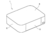
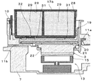
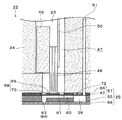
図1は、プリンタ1の外観構成を説明する斜視図であり、図2は、プリンタ1の内部構成を示す平面図である。また、図3は、図2におけるA−A線断面図であり、図4は、図2におけるB−B線断面図である。本実施形態におけるプリンタ1は、プリンタ本体の筐体2の内部にインクジェットヘッドの一種であるインクジェット式記録ヘッド(以下、記録ヘッド3と略記する。)をキャリッジ10に搭載して備え、当該記録ヘッド3のノズル63からインク(液体の一種)を記録用紙やはがき等(記録媒体あるいは液体着弾対象の一種)に対して噴射することにより、当該記録用紙等に写真画像やテキスト等の印刷を行うように構成されている。筐体2の上面側には本体カバー4が、筐体2の前面側には前面カバー5が、それぞれ設けられている。これらの本体カバー4および前面カバー5は互いに連結されており、前面側の縁部を持ち上げることで筐体2の背面側の縁部を軸として背面側まで回動して、筐体2の上面を開放することができるように構成されている。この本体カバー4および前面カバー5を開いた状態では、これらのカバー4,5は、記録用紙等がセットされる給紙トレイとして機能する。また、カバーを開いた状態ではインクカートリッジ17の交換作業等が行える。
FIG. 1 is a perspective view illustrating an external configuration of the
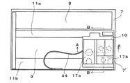
筐体2の内部は、記録用紙等をプラテン9側に給紙する図示しない給紙機構等が設けられた区画である給紙部8aと、プラテン9上に給紙された記録用紙等に対して記録ヘッド3により印刷(記録動作)が行われる区画である印刷部8bとに、金属製の本体フレーム7によって区画されている。本体フレーム7の印刷部8bの背面側と前面側には、それぞれガイドフレーム11a,11bが筐体2の長手方向に沿って互いに平行に設けられている。キャリッジ10は、その前後をガイドフレーム11a,11bによって支持されている。このキャリッジ10は、後述するキャリッジ移動機構85(図6参照)の駆動モーターによる駆動力によってこれらのガイドフレーム11a,11bに沿って案内されて往復移動可能に構成されている。
The inside of the
キャリッジ10の移動範囲の一端側(図2中右側)には、記録ヘッド3の待機位置であり、走査の基点であるホームポジションが設定されている。このホームポジションには、一端側から順にキャッピング機構13(キャッピング手段)および、ワイピング機構14(ワイピング手段)が設けられている。キャッピング機構13は、例えば、エラストマー等の弾性部材からなるキャップ15を有しており、当該キャップ15を、記録ヘッド3のノズル面の周囲を囲むように設けられたヘッドカバー26(図7および図8参照)に対して当接させて封止した状態(キャッピング状態)あるいは当該ヘッドカバー26から離隔した待避状態に変換可能に構成されている。キャッピング機構13は、上記キャッピング状態では、図示しないポンプによりキャップ15の内部を負圧化することができ、これにより、記録ヘッド3のノズル63からインクや気泡を排出するクリーニング動作を行うことができるように構成されている。また、このキャップ15は、フラッシング処理の際に噴射されたインクを受けるインク受部としても機能する。
A home position, which is a standby position of the
ワイピング機構14は、ワイパー16によって記録ヘッド3のノズル面を払拭するものであり、ワイパー16をノズル面に対して当接した状態あるいは当該ノズル面から離隔した待避状態に変換可能に構成されている。ワイパー16は、種々の構成のものを採用することができるが、例えば、樹脂等からなるブレード本体の表面に撥水膜を形成したものや、ノズル面との接触部が布からなる布ワイパー等を採用することができる。本実施形態においては、ワイパー16が記録ヘッド3のノズル面に当接した状態で、キャリッジ10が主走査方向に移動することで、ワイパー16がノズル面を摺動して払拭する。なお、記録ヘッド3が移動を停止した状態でワイパー16が自走することでノズル面を払拭する構成を採用することもできる。要するに、記録ヘッド3とワイパー16が相対的に移動してノズル面が払拭される構成であればよい。
The
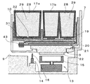
本実施形態における記録ヘッド3は、ホルダー19、流路プレート20、回路基板21、および、ヘッドユニット22を備えている。また、ヘッドユニット22は、ヘッドユニット構成部品として、振動子ユニット23、ヘッドケース24、および流路ユニット25等を備えている。
The
ホルダー19は、例えば合成樹脂により作製された部材であり、インク貯留部材の一種であるインクカートリッジ17が装着される部分である。本実施形態におけるホルダー19には、ブラックインクカートリッジ17aおよびカラーインクカートリッジ17bが装着可能である。これらのインクカートリッジ17は、内部に区画されたインク貯留室28内に、例えば、ポリウレタンフォーム等の多孔質体からなる吸収体29を備え、この吸収体29にインクを吸収・保持している。各インクカートリッジ17の下面(すなわち、ホルダー19のカートリッジ装着面側の面)には、インク導出部32が設けられており、このインク導出部32からインク貯留室28内のインクが導出される。また、各インクカートリッジ17には、接点ROM30(図6参照)が設けられている。この接点ROM30は、例えば半導体記憶手段の一種であるEEPROMにより構成されている。この接点ROM30には、インクカートリッジ17に関する各種の情報が記録されている。この情報としては、例えば、プリンタ1の機種を示す機種コード、製造年月日等の日付コード、インク情報等が記録されている。インク情報には、初期のインク量、インク残量、染料や顔料等の色材やインクの色を示す材料コード、色材濃度情報、粘度情報等が含まれている。
The
ホルダー19の上面においてインクカートリッジが装着される部分には、インク導入部31が設けられている。このインク導入部31は、インクカートリッジ17のインク導出部32と接続される部分であり、インクの色毎に設けられている。本実施形態においては、ブラックインク、シアンインク、マゼンタインク、およびイエローインクの合計4色のインクに対応して、インク導入部31が合計4か所設けられている。このインク導入部31は、円筒部分の開口内に図示しないフィルターおよび多孔質部材(吸液材)を備えている。また、インクカートリッジ17のインク導出部32内にも多孔質部材が設けられており、インク導出部32とインク導入部31とが接続されると、これらの多孔質部材同士が接触して毛細管力によりインクの授受が行われる。インク導入部31からインクが導入されると、フィルターにより濾過された後、流路プレート20に設けられた中間流路(図示せず)を通じてヘッドユニット22側に印加される。また、ホルダー19の上面においてインクカートリッジが装着される部分には、インクカートリッジ17の接点ROM30と導通する接点端子33が設けられている(図6参照)。
An
流路プレート20とヘッドユニット22のヘッドケース24との間には、回路基板21が配設される。この回路基板21は、プリンタ本体側から圧電素子48へ送られる駆動信号やその他の制御信号等を中継する基板である。この回路基板21は、後述するフレキシブルケーブル50の端子部と電気的に接続される端子部(図示せず)が形成されると共に、プリンタ本体側との接続のためのコネクター43やその他の電子部品等を実装している。コネクター43にはFFC(フレキシブルフラットケーブル)44が接続され(図2参照)、回路基板21は、このFFC44を介してプリンタ本体側から駆動信号等を受けるようになっている。
A
図5は、ヘッドユニット22の構成を説明する要部断面図である。ヘッドケース24は、主としてエポキシ系樹脂等の合成樹脂により作製された部材である。このヘッドケース24において流路ユニット25が接合される部分は、例えばステンレス鋼等の金属により作製されて剛性が高められている。また、このヘッドケース24の内部には振動子ユニット23を収納するための収納空部47が高さ方向を貫通する状態で形成されている。このヘッドケース24において、収納空部47に対してキャリッジ走査方向の外側に外れた位置には、ケース流路51が、高さ方向を貫通する状態で形成されている。このケース流路51の上流端は、ヘッドケース24の上面に開口し、流路プレート20の中間流路と連通する。また、ケース流路51の下流端は、ヘッドケース24の下面に開口し、流路ユニット25における共通液室59と連通する。さらに、ヘッドケース24において、ケース流路51に対してノズル列方向に外れた位置には、大気開放連通路52が形成されている。この大気開放連通路52は、大気開放路の一部を構成する通路であり、その一端は、ヘッドケース24の上面に開口して、流路プレート20の大気開放用溝40と上記貫通孔を介して連通する。また、大気開放連通路52の下流端は、ヘッドケース24の下面に開口し、コンプライアンス空間73と連通する。
FIG. 5 is a cross-sectional view of a main part for explaining the configuration of the
振動子ユニット23は、アクチュエーターの一種として機能する圧電素子48と、この圧電素子48が接合される固定板49と、圧電素子48に駆動信号等を印加するためのフレキシブルケーブル50と、を備えている。圧電素子48は、圧電体層と電極層とを交互に積層した圧電板を櫛歯状に切り分けることで作製された積層型であって、積層方向(電界方向)に直交する方向に伸縮可能(電界横効果型)な縦振動モードの圧電素子である。
The
流路ユニット25は、流路基板55の一方の面にノズル基板56を、流路基板55の他方の面に振動板57をそれぞれ接合して構成されている。すなわち、流路基板55、ノズル基板56、および、振動板57は、流路ユニット構成部材(構成部品)である。この流路ユニット25には、共通液室59(リザーバー)と、インク供給口60と、圧力室61と、ノズル連通口62と、ノズル63とを設けている。そして、インク供給口60から圧力室61及びノズル連通口62を経てノズル63に至る一連のインク流路が、各ノズル63に対応して形成されている。また、流路ユニット構成部材は、いずれもノズル列方向に長尺な板材から構成されている。
The
流路ユニット構成部材のうち最下層に配置されるノズル基板56は、ドット形成密度に対応したピッチ(例えば180dpi)で複数のノズル63が穿設された板材である。ノズル基板56の材料としては、ステンレス鋼等の金属板やシリコン単結晶基板等を採用することができる。このノズル基板56には、複数のノズル63を列設してなるノズル列64(ノズル群)が2列設けられており、1つのノズル列64は、例えば180個のノズル63によって構成される。このノズル基板56の下面(ノズル63からインクが噴射される側の面)がノズル面である。なお、ノズル基板56に形成されるノズル列64の本数や、ノズル列64を構成するノズル63の数およびピッチについては、本実施形態で例示したものには限られず、種々の構成のものを採用することができる。
The
流路ユニット構成部材のうちの最上層である振動板57は、支持板54の表面に弾性膜55を積層した二重構造である。本実施形態では、ステンレス鋼等の金属板を支持板54とし、この支持板54の表面に樹脂フィルムが弾性膜55としてラミネートされた複合板材により振動板57が構成されている。この振動板57には、圧力室61の容積を変化させるダイヤフラム68が設けられている。上記のダイヤフラム68は、エッチング加工等によって支持板54を部分的に除去することで作製される。即ち、このダイヤフラム68は、圧電素子48の自由端部の先端面が接合される島部69と、この島部69の周囲に設けられた可撓部70とからなる。島部69には圧電素子48の先端面が接合される。そして、この圧電素子48の自由端部を伸縮させることでダイヤフラム68を変位させて圧力室61の容積を変動させることができる。
The
また、この振動板57において、流路基板55の共通液室59に対応する部分には、当該共通液室59を封止するコンプライアンス部72が設けられている。このコンプライアンス部72は、共通液室59の開口面に相対する領域の支持板31を、エッチング加工等によって除去して当該部分を弾性膜55のみとすることにより作製される。そして、コンプライアンス部72は、共通液室59に貯留された液体の圧力変動を吸収するダンパーとして機能する。なお、この振動板57において支持板54が流路基板55に接合され、弾性膜55がヘッドケース24と接合される。
Further, in the
本実施形態における流路基板55は、インク流路を区画する空部、具体的には、共通液室59となる空部、インク供給口60となる空部、及び、圧力室61となる空部が区画形成された板状の部材である(以下、これらの空部をそれぞれ単に共通液室59、インク供給口60、および圧力室61と称する)。この流路基板55は、例えば、結晶性基材の一種であるシリコンウェハーを異方性エッチング処理することによって作製されている。
The
図6は、プリンタ1の電気的な構成を説明するブロック図である。
本実施形態におけるプリンタ1は、例えばコンピュータ等の電子機器等の外部装置74と無線又は有線で電気的に接続されており、この外部装置74から記録用紙等に画像やテキストを印刷させるため、その画像等に応じた印刷データを受信する。このプリンタ1は、プリンタコントローラ755とプリントエンジン76とを有している。また、このプリンタ1には、インクカートリッジ17の接点ROM30と導通する接点端子33が設けられている。
FIG. 6 is a block diagram illustrating the electrical configuration of the
The
プリンタコントローラ75は、プリンタの各部の制御を行う制御ユニットである。本実施形態におけるプリンタコントローラ75は、インタフェース(I/F)78と、中央演算処理装置(CPU)79と、記憶部81と、駆動信号生成回路82と、を有する。インタフェース78は、外部装置74からプリンタ1へ印刷データや印刷命令を送ったり、プリンタ1の状態情報を外部装置74側に出力したりする際にプリンタの状態データの送受信を行う。CPU79は、プリンタ全体の制御を行うための演算処理装置であり、本発明における制御回路の一種である。記憶部81は、CPU79のプログラムや各種制御に用いられるデータを記憶する素子であり、ROM、RAM、NVRAM(不揮発性記憶素子)を含む。CPU79は、記憶部81に記憶されているプログラムに従って、各ユニットを制御する。また、本実施形態におけるCPU79は、外部装置74からの印刷データに基づき、記録処理時にどのノズル63からどのタイミングでインクを噴射させるかを示す噴射データを生成し、当該噴射データを記録ヘッド3のドライバIC80に送信する。ドライバIC80は、噴射データに基づき、圧電素子48に対する駆動信号の選択印加制御を行う。さらに、本実施形態におけるCPU79は、メンテナンス処理の一種であるフラッシング処理を記録ヘッド3に行わせる。駆動信号生成回路82は、記録用紙等に対して記録ヘッド3のノズル63からインクを噴射させて画像等を記録するための駆動パルスを発生する。
The
次に、プリントエンジン76について説明する。本実施形態におけるプリントエンジン76は、紙送り機構84、紙送り機構85、リニアエンコーダ86、記録ヘッド3、および、接点端子33等を備えている。紙送り機構85は、上記キャリッジ10と、このキャリッジ10を、ガイドフレーム11a,11bに沿って移動させる駆動モーター(例えば、DCモーター。図示せず。)等からなり、キャリッジ10に搭載された記録ヘッド3を主走査方向に移動させる。紙送り機構84は、紙送りモーター及び紙送りローラー等(いずれも図示せず)を備え、給紙部9からの記録用紙等をプラテン9上に順次送り出して副走査を行う。また、リニアエンコーダ86は、キャリッジ10に搭載された記録ヘッド3の走査位置に応じたエンコーダーパルスを、主走査方向における位置情報としてプリンタコントローラ75に出力する。プリンタコントローラ75のCPU79は、リニアエンコーダ86側から受信したエンコーダーパルスに基づいて記録ヘッド3の走査位置(現在位置)を把握することができる。
Next, the
上記の接点端子33は、記録ヘッド3のホルダー19に装着されたインクカートリッジ17の接点ROM30と電気的に接続可能に構成されている。そして、この接点端子33はプリンタコントローラ75のCPU79に電気的に接続されているので、インクカートリッジ17が記録ヘッド3に装着されると、CPU79は、接点ROM30に記録された各種の情報を読み出すことができる。また、CPU79は、接点端子33と接点ROM30との接続状態に基づいて、インクカートリッジ17の記録ヘッド3に対する脱着を検出できる。また、CPU79は、インクカートリッジ17の装着状態において、接点ROM30に記録された各種の情報を書き換えることもできる。本実施形態における接点ROM30および接点端子33は、本発明における装着検出部として機能する。
The
ここで、本実施形態におけるプリンタ1で扱われるインクカートリッジ17は、上述したように吸収体29にインクを保持する所謂フォームタイプのインクカートリッジである。このため、このインクカートリッジ17がプリンタ1に新規に装着された当初に記録ヘッド3側に導入されるインクの粘度は、仕様上で想定されている粘度(例えば、接点ROM30に記録されたインク情報の粘度)よりも高い傾向となる。この点を考慮することなく通常の印刷処理を行うと、比較的高い粘度の影響によりノズル63に対するインクの供給が追い付かず、これにより吐出不良が生じる虞がある。そこで、本発明に係るプリンタ1では、インクカートリッジ17が新たに装着された場合には、想定されている粘度よりも高い粘度に対応した処理が行われる。以下、この点について説明する。
Here, the
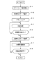
図7は、プリンタ1の動作について説明するフローチャートである。
本実施形態におけるプリンタ1では、上述したように接点端子33と接点ROM30との接続状態に基づいて、新規のインクカートリッジ17の装着を検出する(ステップS1。本発明における第1の工程に相当。)。新規のインクカートリッジ17の装着が検出されると、CPU79は、プリンタ1において選択可能な吐出モードのうち、初期吐出モード(本発明における第1の動作モードに相当)を選択する(ステップS2。本発明における第2の工程に相当。)。この吐出モードに関し、単位時間あたりの吐出量の違いにより初期吐出モードと通常吐出モード(本発明における第2の動作モードに相当)の2種類が選択可能となっている。通常吐出モードは、インクカートリッジ17内のインクの粘度が安定した状態、つまり、インクの粘度勾配および濃度勾配が解消されて、プリンタ1の仕様上想定されている粘度(あるいは概ねこれと同程度の粘度)となった状態におけるインクの吐出に対応したモードである。これに対し、初期吐出モードは、仕様上で想定されている粘度よりも高い粘度のインクの吐出に対応したモードである。
FIG. 7 is a flowchart for explaining the operation of the
In the
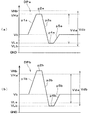
図8は、圧電素子48を駆動してノズル63からインクを吐出させるための駆動パルスの構成を説明する波形図であり、(a)は初期吐出モードで使用される第1駆動パルスDPa、(b)は通常吐出モードで使用される第2駆動パルスDPbをそれぞれ示している。本実施形態においては、第1駆動パルスDPaは、記録用紙等に対して画像等を印刷する印刷処理と、後述するフラッシング処理とにおいて共通に使用される駆動パルスである。
FIG. 8 is a waveform diagram illustrating the configuration of a drive pulse for driving the
第1駆動パルスDPaは、基準電位Vbから第1膨張電位VHaまで一定勾配で電位を上昇させる第1予備膨張要素p1aと、第1予備膨張要素p1aの後端電位である第1膨張電位VHaを一定時間維持する第1膨張ホールド要素p2aと、第1膨張電位VHaから第1収縮電位VLaまで比較的急峻な勾配で電位を降下させる第1収縮要素p3aと、第1収縮電位VLaを一定時間維持する第1収縮ホールド要素p4aと、第1収縮電位VLaから基準電位Vbまで一定勾配で電位を復帰させる第1復帰膨張要素p5aとから構成されている。 The first drive pulse DPa includes a first preliminary expansion element p1a that increases the potential from the reference potential Vb to the first expansion potential VHa with a constant gradient, and a first expansion potential VHa that is a rear end potential of the first preliminary expansion element p1a. A first expansion hold element p2a that maintains a fixed time, a first contraction element p3a that drops a potential with a relatively steep gradient from the first expansion potential VHa to the first contraction potential VLa, and a first contraction potential VLa that are maintained for a fixed time The first contraction hold element p4a, and the first return expansion element p5a that returns the potential with a constant gradient from the first contraction potential VLa to the reference potential Vb.
上記第1駆動パルスDPaが圧電素子48に印加されると、まず、第1予備膨張要素p1aの電位変化に応じて圧電素子48が収縮し、これに伴って圧力室61が基準電位Vbに対応する基準容積から第1膨張電位VHaに対応する膨張容積まで膨張する。これにより、ノズル63内のメニスカスが圧力室61側に引き込まれる。この圧力室61の膨張状態は、第1膨張ホールド要素p2aの印加期間中に亘って一定に維持される。第1膨張ホールド要素p2aの後に続いて第1収縮要素p3aが圧電素子48に印加されると当該圧電素子48が伸長し、これにより、圧力室61が上記最大容積から第1収縮電位VLaに対応する収縮容積まで急激に収縮する。この圧力室61の急激な収縮によって圧力室61内のインクが加圧され、これにより、ノズル63からインク滴が吐出される。この圧力室61の収縮状態は、第1収縮ホールド要素p4aの印加期間に亘って維持され、その後、第1復帰膨張要素p5aが圧電素子48に印加されて、圧力室61が第1収縮電位VLaに対応する容積から基準電位Vbに対応する基準容積まで復帰する。
When the first drive pulse DPa is applied to the
第2駆動パルスDPbは、基準電位Vbから第2膨張電位VHbまで一定勾配で電位を上昇させる第2予備膨張要素p1bと、第2予備膨張要素p1bの後端電位である第2膨張電位VHbを一定時間維持する第2膨張ホールド要素p2bと、第2膨張電位VHbから第2収縮電位VLbまで比較的急峻な勾配で電位を降下させる第2収縮要素p3bと、第2収縮電位VLbを一定時間維持する第2収縮ホールド要素p4bと、第2収縮電位VLbから基準電位Vbまで一定勾配で電位を復帰させる第2復帰膨張要素p5bとから構成されている。この第2駆動パルスDPbは、第1駆動パルスDPaよりも駆動電圧が高められている。より具体的には、第1駆動パルスDPaにおける最低電位である第1収縮電位VLaと最高電位である第1膨張電位VHaとの電位差Vdaに対し、第2駆動パルスDPbにおける最低電位である第2収縮電位VLbと最高電位である第2膨張電位VHbとの電位差Vdbがより大きく設定されている。これにより、第2駆動パルスDPbが圧電素子48に印加されてノズル63から吐出されるインク滴の1滴あたりの量が多くなる。したがって、第1駆動パルスDPaと第2駆動パルスDPbとで、それぞれノズル63からインクを同じ回数吐出させたときに、単位時間あたりの吐出量は、第1駆動パルスDPaで吐出させた場合の方が少なくなる。ここで、単位時間あたりの吐出量とは、個々のノズル63からインクを吐出した時間(例えば、駆動信号生成回路82が駆動パルスを発生する周期のうち、実際に圧電素子48に駆動パルスが印加されてノズル63からインクが吐出される周期)を積算し、その間に噴射されたインクの総量を積算時間で除算してノズル毎に得られた量を意味する。各ノズル63において同じ駆動パルスを用いてインクを噴射させた場合、各ノズル63の単位時間あたりの吐出量は概ね同程度に揃う。
The second drive pulse DPb includes a second pre-expansion element p1b that increases the electric potential with a constant gradient from the reference potential Vb to the second expansion potential VHb, and a second expansion potential VHb that is a rear end potential of the second pre-expansion element p1b. A second expansion hold element p2b that maintains a constant time, a second contraction element p3b that drops a potential with a relatively steep gradient from the second expansion potential VHb to the second contraction potential VLb, and a second contraction potential VLb that maintains the constant time The second contraction hold element p4b, and the second return expansion element p5b that returns the potential with a constant gradient from the second contraction potential VLb to the reference potential Vb. The drive voltage of the second drive pulse DPb is higher than that of the first drive pulse DPa. More specifically, the second potential that is the lowest potential in the second drive pulse DPb with respect to the potential difference Vda between the first contraction potential VLa that is the lowest potential in the first drive pulse DPa and the first expansion potential VHa that is the highest potential. The potential difference Vdb between the contraction potential VLb and the second expansion potential VHb that is the highest potential is set to be larger. As a result, the second drive pulse DPb is applied to the
上記ステップS2で初期吐出モードが選択されると、本実施形態においては続いてフラッシング処理が行われる(ステップS3。)。このフラッシング処理は、キャリッジ10をホームポジションにおけるキャッピング機構13の上方まで移動させ、この状態で、記録ヘッド3の全ノズル63からキャップ15に向けてインクを所定回数吐出させる(つまり、捨て撃ちする)処理である。このフラッシング処理では、上記第1駆動パルスDPaを用いてインクが吐出される。これにより、インクカートリッジ17が新規に装着されて最初の最も粘度の高い、つまり、最も吐出不良が発生する可能性が最も高いインクがキャップ15に排出される。また、このフラッシング処理により、インクの流れが生じるので、インクカートリッジ17内のインクにおける濃度および粘度の均一化が促進される。
When the initial ejection mode is selected in step S2, the flushing process is subsequently performed in the present embodiment (step S3). In this flushing process, the
フラッシング処理において所定回数(所定量)のインクの吐出が完了したならば、続いて、初期吐出モードが維持されたまま、印刷処理に移行する(ステップS4。)。すなわち、プラテン9上に搬送される記録用紙等に対し、第1駆動パルスDPaにより圧電素子48が駆動されてノズル63からインクが吐出されることにより画像等が印刷される。なお、本実施形態においては、初期吐出モードにおけるフラッシング処理で用いられる駆動パルスと、同じく初期吐出モードにおける印刷処理で用いられる駆動パルスが、いずれも第1駆動パルスDPaである構成を例示したが、必ずしも同じでなくてもよい。要は、通常吐出モードにおける印刷処理で用いられる駆動パルスの場合と比較して、単位時間あたりの吐出量が少ない駆動パルスであれば、フラッシング処理と印刷処理とで異なるものであってもよい。
If the predetermined number of times (predetermined amount) of ink ejection has been completed in the flushing process, the process proceeds to the printing process while the initial ejection mode is maintained (step S4). That is, an image or the like is printed on the recording paper or the like conveyed on the
初期吐出モードでの印刷処理では、上記第1駆動パルスDPaによりインクの吐出が行われるので、各ノズル63における単位時間あたりの吐出量が抑えられる。これにより、インクカートリッジ17が新規に装着された直後の比較的粘度の高いインクを吐出する際にも、ノズル63に対するインクの供給が不足することが抑制され、吐出不良が低減される。また、フラッシング処理と同様に印刷処理においてインクの流れが生じるので、インクカートリッジ17内のインクにおける濃度および粘度の均一化が促進される。ここで、印刷処理中において、CPU79は、初期吐出モードにおいて全ノズル63からそれぞれ吐出されるインク量を累積し(フラッシング処理で吐出されたものも含む)、当該累積値(換言すると総吐出量)が、予め定められた規定量になったか否かを判定する(ステップS5。本発明における第3の工程に相当。)。総吐出量が規定量未満であるとCPU79が判断した場合(No)、ステップS4に戻り、印刷処理を継続する。
In the printing process in the initial ejection mode, ink is ejected by the first drive pulse DPa, so that the ejection amount per unit time at each
一方、ステップS5において、総吐出量が規定量に達したと判断した場合(Yes)、CPU79は、吐出モードを初期吐出モードから通常吐出モードに選択・切り替え(ステップS6。本発明における第4の工程に相当。)、印刷処理を継続する(ステップS7。)。これにより、これ以後、次にインクカートリッジ17が交換されるまでは、インクの吐出には第2駆動パルスDPbが使用される。総吐出量が規定量に達した段階では、インクカートリッジ17内のインクの粘度が安定した状態、つまり、インクの粘度勾配および濃度勾配が解消されて、プリンタ1の仕様上想定されている粘度(あるいは概ねこれと同程度の粘度)となった状態となっているので、第2駆動パルスDPbによりノズル63から問題なく、すなわち、インクの高い粘度に起因した吐出不良の発生のおそれがなく、インクを吐出させることができる。そして、CPU79は、印刷処理が完了したか否か(すなわち、印刷データに基づく一連の印刷ジョブが終了したか否か)を判定し(ステップS8)、未だ終了していない(No)と判断した場合、ステップS7に戻り、印刷処理を継続する。一方、ステップS8において、印刷データに基づく一連の印刷ジョブが終了した(Yes)と判定した場合、処理を終了する。
On the other hand, if it is determined in step S5 that the total discharge amount has reached the specified amount (Yes), the
このように、本発明に係るプリンタ1では、インクカートリッジ17が新規に装着されてからインクの総吐出量が規定量となるまでは初期吐出モードに設定され、総吐出量が規定量となったことを条件に通常吐出モードに設定されるので、初期吐出モードでの印刷処理では単位時間あたりの吐出量が抑えられ、インクカートリッジ17が新規に装着された直後の比較的粘度の高いインクを吐出する際にも、ノズル63に対するインクの供給が不足することが抑制され、吐出不良が低減される。その結果、印刷された画像等の画質の低下を防止することが可能となる。
また、本実施形態では、初期吐出モードで印刷処理も行う(つまり、初期の濃度・粘度が比較的高いインクで印刷処理を行う)ので、その前に実行されるフラッシング処理では吐出回数(吐出量)を抑えてインクの無駄な消費を低減することができる。このため、プリンタ1の小型化に伴ってインクの容量が比較的小さいインクカートリッジ17に対応することが可能となる。
Thus, in the
In this embodiment, the printing process is also performed in the initial ejection mode (that is, the printing process is performed with ink having a relatively high initial density / viscosity). ) Can be suppressed and wasteful consumption of ink can be reduced. For this reason, it becomes possible to cope with the
なお、上記実施形態では、初期吐出モードにおいてフラッシング処理の終了後、印刷処理に移行した後に総吐出量が規定量に達して通常吐出モードに設定される構成を例示したが、これには限られず、例えば、フラッシング処理の実行中に総吐出量が規定量に達し、印刷処理に移行する前に通常吐出モードに設定される構成とすることも可能である。 In the above embodiment, the configuration in which the total discharge amount reaches the specified amount and is set to the normal discharge mode after the transition to the printing process after the completion of the flushing process in the initial discharge mode is illustrated, but the present invention is not limited thereto. For example, a configuration in which the total discharge amount reaches a specified amount during the execution of the flushing process and the normal discharge mode is set before shifting to the printing process may be employed.
以下、上記構成のプリンタ1の評価について説明する。なお比較例として、インクカートリッジ17の装着が検出された後に本実施形態におけるステップS2〜S4を経ないで(初期吐出モードを選択しないで)通常吐出モードで吐出を行う構成を挙げて説明する。
Hereinafter, evaluation of the
[評価1]着弾位置精度評価
本実施形態においてはステップS1〜S4を経た後、比較例においてはステップS1の後にステップS2〜S4を経ることなく、通常吐出モードで記録ヘッド3の各ノズル63から10000発(10000滴)のインク滴を連続的に吐出させた。なお、本実施形態におけるステップS4では総吐出量について予め定められた規定量を0.08〔g〕とした。ノズル列の中心部に位置する所定のノズル63から吐出された10000発のインク滴について、着弾した各液滴の中心位置の中心狙い位置(つまり、インクの飛翔曲り等が生じていない状態における目標とする着弾位置の中心)に対するズレ量dの平均値を求め、以下のように、ズレの程度別に3段階に分けて評価した。
A1:ズレ量dの平均値が0.05〔μm〕未満。
B1:ズレ量dの平均値が0.05〔μm〕以上、0.10〔μm〕未満。
C1:ズレ量dの平均値が0.10〔μm〕以上。
その結果、本実施形態ではA1の評価となったのに対し、比較例ではC1の評価となった。すなわち、ステップS2〜S4の処理を経ない構成では、インクカートリッジ17が装着されてから初期段階でのインクの比較的高い粘度の影響により、ノズル63に対するインクの供給が追い付かずメニスカスが安定しないため、着弾のずれ量が多くなるという結果となった。
[Evaluation 1] Evaluation of landing position accuracy
In this embodiment, after passing through Steps S1 to S4, in the comparative example, after Step S1 and without going through Steps S2 to S4, 10,000 inks (10000 drops) from each
A1: The average value of the shift amount d is less than 0.05 [μm].
B1: The average value of the shift amounts d is 0.05 [μm] or more and less than 0.10 [μm].
C1: The average value of the shift amounts d is 0.10 [μm] or more.
As a result, in this embodiment, the evaluation was A1, whereas in the comparative example, the evaluation was C1. That is, in the configuration that does not go through the processes of steps S2 to S4, the ink supply to the
[評価2]インク滴吐出量の安定性評価
記録ヘッド3のノズル列の両端にそれぞれ位置する2つのノズル63について、10000発(10000滴)のインク滴を連続的に吐出した。吐出されたインク滴の総重量をそれぞれ求め、これを吐出回数で除することで上記2つのノズル63の平均吐出量をそれぞれ算出し、これらの平均吐出量の差の絶対値ΔW〔ng〕を求めた。そして、このΔWの、インク滴の目標吐出量WT〔ng〕に対する比率(ΔW/WT)を求め、以下の3段階の基準に従い、評価した。ΔW/WTの値が小さいほど、インク滴の吐出量の安定性に優れている(すなわち、目標とすると吐出量に対するばらつきが少ない)と言える。
A2:ΔW/WTの値が、0.025未満。
B2:ΔW/WTの値が、0.025以上、0.625未満。
C2:ΔW/WTの値が、0.625以上。
その結果、本実施形態ではA2の評価となったのに対し、比較例ではC2の評価となった。
[Evaluation 2] Stability Evaluation of Ink Droplet Discharge Amount 10,000 ink drops (10000 drops) were continuously discharged from the two
A2: The value of ΔW / WT is less than 0.025.
B2: The value of ΔW / WT is 0.025 or more and less than 0.625.
C2: The value of ΔW / WT is 0.625 or more.
As a result, in this embodiment, the evaluation was A2, while in the comparative example, the evaluation was C2.
[評価3]画質評価
200mm間隔で2本の縦罫線(キャリッジ10の主走査方向に交差(理想的には直交)する方向の罫線)を印刷したときの各罫線を構成するドット位置の主走査方向のばらつき量(平均値)を本実施形態と比較例とでそれぞれ評価した。
A3:ばらつき量 20μm以下
B3:ばらつき量 40μm以下
C3:ばらつき量 60μm以上
その結果、本実施形態ではA3の評価となったのに対し、比較例ではC3の評価となった。
[Evaluation 3] Image quality evaluation Main scanning of dot positions constituting each ruled line when printing two vertical ruled lines (ruled lines in a direction intersecting (ideally orthogonal) to the main scanning direction of the carriage 10) at intervals of 200 mm The amount of variation (average value) in the direction was evaluated for each of the present embodiment and the comparative example.
A3: Variation amount 20 μm or less B3: Variation amount 40 μm or less C3: Variation amount 60 μm or more As a result, this embodiment evaluated A3, while the comparative example evaluated C3.
なお、上記実施形態では、インクの吐出の駆動源となるアクチュエーターとして、所謂縦振動型の圧電素子48を例示したが、これには限られず、静電気力によって圧力室の一部を変位させる所謂静電方式のアクチュエーターや、加熱により液体内に生じる気泡により圧力室内に圧力変動を生じさせる発熱素子等の他のアクチュエーターを採用することが可能である。
In the above embodiment, the so-called longitudinal vibration type
そして、以上では、インクジェットプリンタとして、インクジェットヘッドの一種である記録ヘッド3を搭載したプリンタ1を例に挙げて説明したが、これには限られず、所謂フォームタイプのインクカートリッジが使用される他のインクジェットプリンタにも適用することができる。例えば、液晶ディスプレイ等のカラーフィルターを製造するに色材噴射ヘッドを搭載するディスプレイ製造用プリンタ,有機EL(Electro Luminescence)ディスプレイやFED(面発光ディスプレイ)等の電極を形成する電極材噴射ヘッドを搭載する電極製造用プリンタ等にも適用することができる。
In the above description, the
1…プリンタ,3…記録ヘッド,7…本体フレーム,10…キャリッジ,12…駆動部品,13…キャッピング機構,15…キャップ,17…インクカートリッジ,29…吸収体,30…接点ROM,33…接点端子,48…圧電素子,61…圧力室,63…ノズル,79…CPU,82…駆動信号生成回路
DESCRIPTION OF
Claims (2)
前記インク貯留部材から導入したインクを噴射するインクジェット記録ヘッドと、
前記インクジェット記録ヘッドによるインクの噴射を制御する制御回路と、
を備え、
前記制御回路は、前記装着検出部により新規のインク貯留部材の装着が検出された場合、第1の動作モードに設定し、その後、第1の動作モードにおけるインクの総吐出量が規定量に到達したことを条件に第2の動作モードに設定する制御を行い、
前記第1の動作モードにおけるインク吐出時の単位時間当たりの吐出量は、前記第2の動作モードにおけるインク吐出時の単位時間当たりの吐出量よりも少なく設定されたことを特徴とするインクジェットプリンタ。 A mounting detection unit that detects that an ink storage member that holds ink is mounted on the absorber housed therein;
An ink jet recording head for ejecting ink introduced from the ink storage member;
A control circuit for controlling ejection of ink by the inkjet recording head;
With
The control circuit sets the first operation mode when the installation detection unit detects the installation of a new ink storage member, and then the total ejection amount of the ink in the first operation mode reaches a specified amount. On the condition that the second operation mode is set,
The ink jet printer according to claim 1, wherein a discharge amount per unit time at the time of ink discharge in the first operation mode is set to be smaller than a discharge amount per unit time at the time of ink discharge in the second operation mode.
前記インク貯留部材が装着されたことを検出する第1の工程と、
第1の動作モードに設定する第2の工程と、
第1のモードにおけるインクの総吐出量が規定量に到達したことを検知する第3の工程と、
前記第3の工程における検知を条件に第2の動作モードに設定する第4の工程と、を含み、
前記第1の動作モードにおけるインク吐出時の単位時間当たりの吐出量は、前記第2の動作モードにおけるインク吐出時の単位時間当たりの吐出量よりも少ないことを特徴とするインクジェットプリンタの制御方法。 An ink storage member that holds ink in an absorber housed therein, and a method for controlling an ink jet printer including an ink jet recording head that ejects ink introduced from the ink storage member,
A first step of detecting that the ink storage member is mounted;
A second step of setting the first operation mode;
A third step of detecting that the total ejection amount of the ink in the first mode has reached a specified amount;
A fourth step of setting the second operation mode on condition of detection in the third step,
An ink jet printer control method, wherein an ejection amount per unit time during ink ejection in the first operation mode is smaller than an ejection amount per unit time during ink ejection in the second operation mode.
Priority Applications (3)
| Application Number | Priority Date | Filing Date | Title |
|---|---|---|---|
| JP2014129987A JP2016007789A (en) | 2014-06-25 | 2014-06-25 | Ink jet printer and control method of the same |
| CN201510350186.8A CN105313459B (en) | 2014-06-25 | 2015-06-23 | Ink jet printer and control method therefor |
| US14/749,457 US9375918B2 (en) | 2014-06-25 | 2015-06-24 | Ink jet printer and control method therefor |
Applications Claiming Priority (1)
| Application Number | Priority Date | Filing Date | Title |
|---|---|---|---|
| JP2014129987A JP2016007789A (en) | 2014-06-25 | 2014-06-25 | Ink jet printer and control method of the same |
Publications (1)
| Publication Number | Publication Date |
|---|---|
| JP2016007789A true JP2016007789A (en) | 2016-01-18 |
Family
ID=54929571
Family Applications (1)
| Application Number | Title | Priority Date | Filing Date |
|---|---|---|---|
| JP2014129987A Pending JP2016007789A (en) | 2014-06-25 | 2014-06-25 | Ink jet printer and control method of the same |
Country Status (3)
| Country | Link |
|---|---|
| US (1) | US9375918B2 (en) |
| JP (1) | JP2016007789A (en) |
| CN (1) | CN105313459B (en) |
Cited By (2)
| Publication number | Priority date | Publication date | Assignee | Title |
|---|---|---|---|---|
| JP2018165004A (en) * | 2017-03-28 | 2018-10-25 | セイコーエプソン株式会社 | Liquid discharge apparatus and liquid discharge method |
| JP2019069567A (en) * | 2017-10-10 | 2019-05-09 | ブラザー工業株式会社 | Liquid discharge device |
Families Citing this family (1)
| Publication number | Priority date | Publication date | Assignee | Title |
|---|---|---|---|---|
| CN110978795A (en) * | 2019-12-18 | 2020-04-10 | 无锡市宸豪科技有限公司 | Spray head based on code spraying printer |
Family Cites Families (11)
| Publication number | Priority date | Publication date | Assignee | Title |
|---|---|---|---|---|
| JPH0631932A (en) * | 1992-07-14 | 1994-02-08 | Fuji Xerox Co Ltd | Ink-jet recording device |
| JPH08183170A (en) * | 1994-12-28 | 1996-07-16 | Canon Inc | Ink jet recording device |
| JPH1067127A (en) * | 1996-04-23 | 1998-03-10 | Canon Inc | Ink jet recording device and image processing method |
| US6293663B1 (en) * | 1998-10-27 | 2001-09-25 | Canon Kabushiki Kaisha | Ink tank |
| JP2000127431A (en) | 1998-10-27 | 2000-05-09 | Canon Inc | Ink tank |
| WO2001087626A1 (en) * | 2000-05-18 | 2001-11-22 | Seiko Epson Corporation | Method and apparatus for detecting consumption of ink |
| JP4012023B2 (en) * | 2002-09-09 | 2007-11-21 | キヤノン株式会社 | Inkjet recording method, recording system, inkjet recording apparatus, control method, and program |
| JP2004154763A (en) * | 2002-09-12 | 2004-06-03 | Seiko Epson Corp | Film manufacturing apparatus and its driving method, and device manufacturing method, device manufacturing apparatus, and device |
| WO2005007414A1 (en) * | 2003-07-17 | 2005-01-27 | Matsushita Electric Industrial Co. Ltd. | Waste ink tank and ink jet printer apparatus using the same |
| JP5552778B2 (en) * | 2009-09-02 | 2014-07-16 | セイコーエプソン株式会社 | Liquid supply method |
| JP5742205B2 (en) * | 2010-12-20 | 2015-07-01 | ブラザー工業株式会社 | Ink ejection apparatus and program |
-
2014
- 2014-06-25 JP JP2014129987A patent/JP2016007789A/en active Pending
-
2015
- 2015-06-23 CN CN201510350186.8A patent/CN105313459B/en active Active
- 2015-06-24 US US14/749,457 patent/US9375918B2/en active Active
Cited By (3)
| Publication number | Priority date | Publication date | Assignee | Title |
|---|---|---|---|---|
| JP2018165004A (en) * | 2017-03-28 | 2018-10-25 | セイコーエプソン株式会社 | Liquid discharge apparatus and liquid discharge method |
| JP2019069567A (en) * | 2017-10-10 | 2019-05-09 | ブラザー工業株式会社 | Liquid discharge device |
| JP6996211B2 (en) | 2017-10-10 | 2022-01-17 | ブラザー工業株式会社 | Liquid drainer |
Also Published As
| Publication number | Publication date |
|---|---|
| CN105313459A (en) | 2016-02-10 |
| US9375918B2 (en) | 2016-06-28 |
| US20150375502A1 (en) | 2015-12-31 |
| CN105313459B (en) | 2017-04-12 |
Similar Documents
| Publication | Publication Date | Title |
|---|---|---|
| CN108528048B (en) | Liquid droplet ejection apparatus, monitoring system, and method for determining whether ejection head needs to be replaced | |
| US9114612B2 (en) | Liquid ejecting head, substrate for liquid ejecting head, and printing apparatus | |
| JP2008168565A (en) | Fluid jetting device | |
| JP2018051812A (en) | Liquid injection device, flushing adjustment method, control program of liquid injection device and recording medium | |
| JP2015223762A (en) | Liquid injection device, control method of liquid injection head and control method of liquid injection device | |
| US9375918B2 (en) | Ink jet printer and control method therefor | |
| JP2016000475A (en) | Liquid jet device, control method of liquid jet head, and control method of the liquid jet device | |
| US8388087B2 (en) | Liquid ejecting apparatus and method of controlling same | |
| JP2012171261A (en) | Liquid jetting apparatus | |
| JP2004058633A (en) | Inkjet recorder and its ink leakage detecting method | |
| JP7251059B2 (en) | LIQUID EJECTING APPARATUS CONTROL METHOD AND LIQUID EJECTING APPARATUS | |
| JP6451109B2 (en) | Liquid ejection device and method for controlling liquid ejection device | |
| JP2011046091A (en) | Liquid ejector | |
| JP4063067B2 (en) | Liquid ejector | |
| JP2009160828A (en) | Liquid delivering apparatus and its controlling method | |
| JP2011207078A (en) | Liquid ejecting apparatus and method for controlling the same | |
| US20120256986A1 (en) | Liquid ejecting apparatus and method of controlling liquid ejecting apparatus | |
| JP5041161B2 (en) | Liquid ejecting apparatus and liquid ejecting head cleaning method | |
| JP6364772B2 (en) | Liquid ejecting apparatus and method for controlling liquid ejecting apparatus | |
| JP6051610B2 (en) | Liquid ejecting apparatus and method for controlling liquid ejecting apparatus | |
| JP2012179810A (en) | Liquid ejecting apparatus | |
| JP5073577B2 (en) | Droplet ejection apparatus, droplet ejection method, and image forming apparatus | |
| JP6021303B2 (en) | Liquid ejecting apparatus and control method thereof | |
| JP6331759B2 (en) | Inkjet printer | |
| JP2004042443A (en) | Liquid jet apparatus |