JP2004058633A - Inkjet recorder and its ink leakage detecting method - Google Patents
Inkjet recorder and its ink leakage detecting method Download PDFInfo
- Publication number
- JP2004058633A JP2004058633A JP2002224283A JP2002224283A JP2004058633A JP 2004058633 A JP2004058633 A JP 2004058633A JP 2002224283 A JP2002224283 A JP 2002224283A JP 2002224283 A JP2002224283 A JP 2002224283A JP 2004058633 A JP2004058633 A JP 2004058633A
- Authority
- JP
- Japan
- Prior art keywords
- ink
- jet recording
- ink jet
- detecting
- recording apparatus
- Prior art date
- Legal status (The legal status is an assumption and is not a legal conclusion. Google has not performed a legal analysis and makes no representation as to the accuracy of the status listed.)
- Pending
Links
Images


Abstract
Description
【0001】
【発明の属する技術分野】
本発明は、インクジェットプリンタあるいはインクジェットプロッタなどのインクジェット式記録装置に関し、特に、移動しながらインク滴を吐出して記録するその記録ヘッド内でのインク漏れを検出する技術に関する。
【0002】
【従来の技術】
プリンタやファクシミリ装置等に用いられる記録装置には、サーマル式、ワイヤドット式、インクジェット式等種々の方式のものがある。中でも、記録速度が速く、フルカラー化が容易等の理由から、近年、インクジェット式記録装置が多く用いられている。このインクジェット式記録装置は、インクが充填されたインクカートリッジが記録ヘッドに取り付けられ、このインクカートリッジから記録ヘッドにインクが供給される。そして、記録ヘッドに設けられた複数のノズルから記録媒体に対して微小のインク滴が吐出されることにより印字が行われる。インクを吐出する方式としては、種々の方式が存在するが、圧電素子等圧力発生素子のたわみ振動を利用してインク滴を吐出する方式が、吐出されるインク滴の粒径等を制御し易く、高画質化の点で優れている等の理由から、近年、有力な方式となっている。これは、圧力発生室の一部を構成する振動板に、例えば、ピエゾ素子から成る圧力発生素子を張設し、ピエゾ素子のたわみ振動により圧力発生室の容積を変化させてインク滴を吐出するものである。
【0003】
【発明が解決しようとする課題】
ところで、上述したインクジェット式記録ヘッドにおいて、インクカートリッジから記録ヘッドにインクが供給される過程等でインク漏れが発生することがある。このような場合、電極間のショート等により、記録データ上は非印字のノズルからインク滴が吐出される等の事態が生じて所望の印字結果が得られず、高圧電極間でショート等を生じた場合では、発煙することも考えられる。
【0004】
従来、かかるインク漏れ対策を施したインクジェット式記録ヘッド乃至記録装置として、特開平10−193588号公報や特開平10−86357号公報に記載のものが提案されている。
【0005】
しかしながら、特開平10−193588号公報に記載の従来例は、ヘッドごとインクカートリッジ(インクタンク)を交換可能なインクジェット式記録ヘッドにおいて、記録装置本体との電気的接触を得るために記録ヘッドの外部に露出して設けられたパット部に生じたインク漏れを検知する構成のものであり、特に、大電流が流れる電力用パットと他のパットとの間にショート等を生じた場合の検知等を対象としている。また、特開平10−86357号公報に記載の従来例も、記録ヘッド外部のフレキシブル基板上等に設けられたドライバ駆動電源用電極間に生じたインク漏れを検知する構成のものであり、特に、高電圧が印加されている該電極間でのショートや発煙を未然に防止する技術に関するものである。
【0006】
即ち、以上の従来例は、外部の部材との電気的接触等のために記録ヘッド上に設けられた電気的接点におけるインク漏れを検知等する構成のものであり、当該接点及びその近傍におけるインク漏れしか検出し得ない。換言すれば、記録ヘッド内のインク漏れ、例えば、セグメントショート等を検出することはできない。
このように、上記の従来例は、記録ヘッドの内部、特に、上述した圧力発生素子のたわみ振動を利用する方式の記録ヘッドに関して、記録ヘッド内部に生じるインク漏れを検知する構成を示すものではなかった。
【0007】
従って、かかる圧力発生素子のたわみ振動を利用する方式の記録ヘッドに関し、その内部でわずかなインク漏れを生じた場合にも、これを検出し、圧力発生素子を構成する電極間のショート等により非印字のノズルからインク滴が吐出される等の事態を防止し得る技術が望まれている。
【0008】
そこで、本発明の課題は、圧力発生素子のたわみ振動を利用する方式の記録ヘッドの内部でインク漏れを生じた場合を検出し、圧力発生素子を構成する電極間のショート等により望ましくない印字結果を生じる等の事態を防止し得るインクジェット式記録装置及びそのインク漏れ検出方法を提供することにある。
【0009】
【課題を解決するための手段】
上記課題を解決するため、本発明では、記録ヘッド内に圧力発生素子と共にインク漏れ検出用の一対の電極を設け、両電極間の電気的値を検出し、その値が所定の閾値を越えたことをもって、記録ヘッド内のインク漏れを検出するようにした。
【0010】
即ち、本発明の第1の様相によれば、複数のノズルに対応してそれぞれ設けられ、インクに圧力を加える圧力発生素子を含む記録ヘッドを備え、該記録ヘッドの前記圧力発生素子を駆動信号により所定の記録タイミングで選択的に駆動し、前記記録ヘッドの対応するノズルからインク滴を吐出させて記録を行なうインクジェット式記録装置であって、前記記録ヘッド内に前記圧力発生素子と共に設けたインク漏れ検出用の一対の電極と、前記一対の電極間の電気的値を検出する検出手段とを有することを特徴とするインクジェット式記録装置が得られる。
【0011】
かかる構成によれば、一対の電極間の電気的値を検出し、その値が所定の閾値を越えたことをもって記録ヘッド内のインク漏れを検出することができる。
【0012】
更に、前記検出手段により前記電気的値が所定の閾値を越えたことが検出された場合に、所定の警告表示を行う制御手段を有していても良い。
【0013】
かかる構成によれば、所定の警告表示を行うことにより、ユーザは望ましくない印字結果を生じる等の事態を防止し得る。
【0014】
また、本発明の第2の様相によれば、複数の圧力室と、これらの圧力室の一面を封止する振動板と、前記振動板の外面に前記圧力室に対応して配置された下部電極と、これらの下部電極に密着して積層される前記圧力発生素子と、前記圧力発生素子を前記下部電極とで挟み込むように配置した上部電極とで焼成によって形成されているアクチュエータを有するインクジェット式記録装置において、焼成によって形成されたインク漏れ検出用の一対の電極と、前記一対の電極間の電気的値を検出する検出手段とを有することを特徴とするインクジェット式記録装置が得られる。
【0015】
かかる構成によれば、焼成によって形成されたインク漏れ検出用の一対の電極間の電気的値を検出し、その値が所定の閾値を越えたことをもって記録ヘッド内の圧力発生素子近傍のインク漏れを検出することができる。
【0016】
また、前記制御手段は、前記所定の警告表示に代えて、又は前記所定の警告表示に加えて更に、前記記録ヘッドへの電源供給を遮断するようにしても良い。
【0017】
これにより、ユーザの対応如何に拘らず、望ましくない印字結果を生じる等の事態を確実に防止し得る。
【0018】
尚、前記電気的値は、電圧値(電位差)、抵抗値、電流値のいずれでも良い。
【0019】
また、前記インク漏れ検出用の一対の電極は、前記アクチュエータ部材の前記振動板の縁部に前記複数の圧力発生素子を取り囲むように設けられているのが好適である。
【0020】
これにより、アクチュエータ部材上で生じるインク漏れから圧力発生素子を保護することが可能である。
【0021】
更に、前記インク漏れ検出用の一対の電極は、焼成により前記アクチュエータ部材と一体的に構成するのが望ましい。
【0022】
これにより、製造が容易となり、コストの増加を最小限に抑えられる。
【0023】
また、前記アクチュエータ部材の前記インク漏れ検出用の一対の電極間にスリットが形成されているのが好適である。
【0024】
かかる構成であれば、スリットの毛細管力により、インク漏れの検出精度を向上させ得る。
【0025】
更に、本発明の第3の様相によれば、複数のノズルに対応してそれぞれ設けられ、インクに圧力を加える圧力発生素子を含む記録ヘッドを備え、該記録ヘッド内に前記圧力発生素子と共に通常時はオープン状態にあるインク漏れ検出用の一対の電極を設け、前記圧力発生素子を駆動信号により所定の記録タイミングで選択的に駆動し、前記インクを前記対応するノズルからインク滴として吐出させて記録を行なうインクジェット式記録装置のインク漏れ検出方法において、前記インク漏れ検出用の一対の電極間に電圧を印加する工程と、該電圧の変化を測定する工程と、測定結果に応じて前記記録ヘッド内のインク漏れを検出する工程とを有することを特徴とするインク漏れ検出方法が得られる。
【0026】
かかる構成によれば、一対の電極間の電圧変化を測定し、その値如何により記録ヘッド内のインク漏れを検出することができる。
【0027】
尚、前記各工程は、インクジェット式記録装置の電源ON時と印刷開始命令受信時の双方の時に行うようにしても良い。
【0028】
これにより、より確実な頻度でインク漏れを検出することが可能となる。
【0029】
【発明の実施の形態】
図面を参照して、本発明の実施の形態に係るインクジェット式記録装置及びそのインク漏れ検出方法について説明する。
【0030】
尚、以下に述べる実施形態は、本発明の好適な具体例であるから、技術的に好ましい種々の限定が付されているが、本発明の範囲は、以下の説明において特に本発明を限定する旨の記載がない限り、これらの態様に限られるものではない。
【0031】
図1は、本発明の実施形態に係るインクジェット式記録装置の要部を示す斜視図である。
【0032】
図1に示すように、本実施形態のインクジェット式記録装置は、ヘッドユニット100、キャリッジ機構110、紙送り機構120、キャッピング装置130、ワイピング装置140等を備えている。
【0033】
ヘッドユニット100は、キャリッジ101がキャリッジ機構110のタイミングベルト111を介してキャリッジモータ112に接続され、ガイド部材113に案内されて記録用紙Pの紙幅方向に往復動するように構成されている。そして、ヘッドユニット100の記録用紙Pと対向する面、この図に示す例では下面に、インクジェット式記録ヘッド102が取り付けられている。
【0034】
記録ヘッド102は、キャリッジ101の内部に収容されているインクカートリッジ150から、例えば、6色から成るカラーインクの各色ごとのインクの補給を受け、ヘッドユニット100の移動および紙送り機構120の紙送りローラ121による記録用紙Pの移動に合わせて記録用紙Pに各色ごとのインク滴を吐出してドットを形成し画像や文字を印刷するように構成されている。
【0035】
また、キャッピング装置130は、非印刷領域(非記録領域)に配設されており、印刷の休止中に記録ヘッド102のノズル開口を封止し、また、印刷動作中に行われるフラッシング動作による記録ヘッド102からのインク滴を受けるように構成されている。従って、印刷の休止中、インクから溶媒が飛散することによってインクが増粘あるいはインク膜を形成することを抑制して、印刷の休止中にノズルに目詰まりが発生することを防止することができる。ワイピング装置140は、記録ヘッド102の表面をブレードなどでワイピングすることにより、そこに付着したインク滴や紙粉を拭き取るように構成されている。
【0036】
図2は、図1のヘッドユニット100を略示す一部断面図である。図2に示すように、ヘッドユニット100は、キャリッジ101、記録ヘッド102、プリント(ヘッド)基板103を備えている。キャリッジ101は、上面が開放状態にある直方体形状のプラスチック製ケース状からなり、内側にはインクカートリッジ150が収容される。記録ヘッド102は、キャリッジ101の底面部に取り付けられており、詳細は後述する。プリント基板103上には、ヘッド駆動回路等を形成する各種電子部品103aが搭載されており、キャリッジ101の側面部から所定間隔をあけて固定されている。また、プリント基板103上には、後述するインク漏れ検出回路も構成されている。尚、ヘッド駆動回路、インク漏れ検出回路は、プリント基板103上ではなく、別基板上で構成されていてもよい。
【0037】
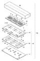
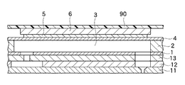
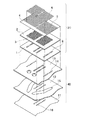
図3は、記録ヘッド102の分解斜視図である。図4は、図3の記録ヘッド102の断面図である。図5は、記録ヘッド102の圧力発生ユニット(アクチュエータ)20と流路ユニット40の一部を示す分解斜視図である。図6は、記録ヘッド102の製造工程を示す図である。
【0038】
図3に示すように、このインクジェット式記録ヘッド102は、ケースヘッド90、圧力発生ユニット(アクチュエータ)20、20、20、供給孔プレート(Sプレート)13、リザーバプレート(Rプレート)12、及びノズルプレート(Nプレート)11とを有している。供給孔プレート(Sプレート)13、リザーバプレート(Rプレート)12及びノズルプレート(Nプレート)11は、流路ユニット40を構成する。
【0039】
ケースヘッド90は、基板が取り付けられ、インクを供給する流路が形成されると共に、以下のアクチュエータ20、20、20、供給孔プレート(Sプレート)13、リザーバプレート(Rプレート)12、及びノズルプレート(Nプレート)11等の各部材を収納し保護するケースとしての機能を持つ。
【0040】
図3、図4及び図5に示すように、本実施形態では、ケースヘッド90と、複数ノズルを縦2列に構成した圧力発生ユニット(アクチュエータ)20を3ユニットと流路ユニット40を用いて記録ヘッド102を構成している。
【0041】
本実施形態の記録ヘッド102は、図3、図4及び図5に示すように、複数の圧電素子6、下部電極5、振動板4、圧電素子6に対応する複数の圧力室3を有する圧力室形成基板2及び連通路9が穿孔された連通路基板1とによって構成された圧力発生ユニット(アクチュエータ)20と、複数のインク供給孔14を有する供給孔プレート(Sプレート)13、インクリザーバ室15を有するリザーバプレート(Rプレート)12、複数のノズル16を有するノズルプレート(Nプレート)11とによって構成された流路ユニット40があり、両ユニットが接着剤により接合されている。
【0042】
接合方法は、スクリーン印刷法、転写法等によってペースト状接着剤を塗布し、加熱硬化させる。また、フィルム状接着剤をプレス加工等によって成型したものを用いることも可能である。この場合、接着方法としては、プレス加工されたフィルム状接着剤を図示しない案内孔を使って位置出しをしながら積層した後、加熱圧着を行う。
【0043】
圧力発生ユニット(アクチュエータ)20は、焼成で一体に形成されるが、まず、一般的な工程を図6の(A)から(C)に示す。図6の(A)において、振動板4と、パンチングによって圧力室3となる部分を形成した圧力室形成基板2と、連通路基板1をアルミナ、ジルコニア等のセラミックス材料であるグリーンシートの状態で加圧し、800℃から1500℃の温度で一体に焼成する。セラミックス材料は、一般的には酸化アルミニウム、酸化ジルコニウム、酸化マグネシウム、窒化アルミニウム、窒化珪素のうち何れかの1種以上を主成分とする材料である。次に、図6の(B)において、下部電極5の材料を印刷によって圧力室3に対応する部分に形成し、焼成する。下部電極5の材料は、白金、パラジウム、銀−パラジウム、銀−白金、白金−パラジウムから成る合金のうち少なくとも1種以上を主成分とする材料である。最後に、図6の(C)において、圧電素子6の材料を同じく印刷によって形成し、焼成して仕上げる。圧電素子6の材料としては、ジルコン酸チタン酸鉛、マグネシウムニオブ酸鉛、ニッケルニオブ酸鉛、亜鉛ニオブ酸鉛、マンガンニオブ酸鉛、アンチモンスズ酸鉛、チタン酸鉛を主成分とする材料である。
【0044】
尚、図3に示すように、供給孔プレート(Sプレート)13には、各色ごとのインク導入口18、18、18・・・が設けられている。尚、供給孔プレート(Sプレート)13上の一点鎖線で示す部分LEAKにおいて、これらインク導入口18、18、18・・・を介してインク漏れを生じる場合がある。
【0045】
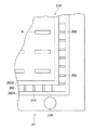
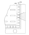
図7は、アクチュエータ20、20、20をそのインク漏れ検出用電極パターン200と共に拡大して示す模式図であり、図8は、図7のインク漏れ検出用電極パターン200の一部を、更に拡大して示す図である。
【0046】
図7に示すように、各アクチュエータ20の外縁部には、2列の圧電素子6を取り囲むように、一対のインク漏れ検出用電極パターン200が形成されている。該一対のインク漏れ検出用電極パターン200は、外側電極200Aと内側電極200Bとから成り、これら外側電極200Aと内側電極200Bとは、通常時オープン状態となっている。外側電極200Aは、例えば、3.3Vの電圧が印加されるように、所定の電源(図示せず)に接続されている。一方、内側電極200Bは、グラウンド接続されている。そして、インク漏れ検出用電極パターン200は、後述するインク漏れ検出回路220により外側電極200Aと内側電極200Bとの間の電位差が検出され、記録装置本体の制御部は、インク漏れ検出回路220によって検出された両電極間の電位差に応じてヘッドドライバへの電源供給を制御する。尚、外側電極200Aと内側電極200B間には任意の電位差を設けるようにして良いが、誤検出を防止するためには、少なくとも3.3V程度の電位差を設けるのが好適である。
【0047】
図7に示すように、各アクチュエータ20、20、20のそれぞれにおいて、各2列の圧電素子6を取り囲むように、各外側電極200Aと各内側電極200Bとから成る一対のインク漏れ検出用電極パターン200が設けられている。尚、本実施形態では、これらインク漏れ検出用電極パターン200は、図3乃至図6に示した記録ヘッド102の製造時に、各アクチュエータ20の振動板4上に、例えば、導電ペーストによりパターン形成され、アクチュエータ20、20、20をそれぞれ焼成する時に一体的に構成される。従って、インク漏れ検出用電極パターン200を設けるために、特別の工程を別個に設けることなく比較的容易に形成し得るので、記録ヘッドのコスト増加を最小限に抑えることも可能である。
【0048】
更に、本実施形態のインクジェット式記録ヘッドにおいては、図8に示すように、各アクチュエータ20の振動板4におけるインク漏れ検出用電極パターン200の外側電極200Aと内側電極200Bとの間に両電極間を連通する複数のスリット202が形成されている。これらスリット202の機能については後述する。尚、図7及び図8において、符号204乃至209は、6色から成るカラーインクの各色ごとに供給孔プレート(Sプレート)13に設けられたインク導入口18、18、18・・・にそれぞれ対応するアクチュエータ20、20、20上の箇所を示す。図3に関して前述したように、供給孔プレート(Sプレート)13上の一点鎖線で示す部分LEAKにおいて、インク導入口18、18、18・・・を介してインク漏れを生じる場合には、アクチュエータ20、20、20上において、インク導入口18、18、18・・・に対応する箇所204乃至209から各アクチュエータ20の外縁部に回り込むようにインク漏れを生じることが多い。本実施形態のインクジェット式記録ヘッド102では、図7に示したように、各アクチュエータ20の外縁部に圧電素子6を取り囲むように、一対のインク漏れ検出用電極パターン200が形成されているので、このように対応箇所204乃至209から各アクチュエータ20の外縁部に回り込むように生じるインク漏れから圧電素子6を保護するのに極めて有効な電極パターン形状であると言える。
【0049】
次に、本実施形態のインクジェット式記録装置の制御系の構成について、図9を参照して説明する。
【0050】
図9は、本実施形態のインクジェット式記録装置の全体構成を表す機能ブロック図である。図9において、本実施形態のインクジェット式記録装置は、プリンタコントローラ340及びプリントエンジン305とから概略構成されている。プリンタコントローラ340は、ホストコンピュータ(図示せず)からの多値階層情報を含む記録データ等を受信するインターフェース(I/F)343と、多値階層情報を含む記録データ等の各種データの記憶を行うRAM344と、各種データ処理を行うためのルーチン等を記憶したROM345と、CPU306a等からなる制御部306と、発振回路347と、ヘッドユニット100内のアナログスイッチ回路316を介して記録ヘッド102に印加される駆動信号COMを発生させる駆動信号発生回路308と、ドットパターンデータに展開された記録データSI及び駆動信号COMをプリントエンジン305に送信する等の機能を担うインターフェース349とを備えている。
【0051】
本実施形態では、ヘッドドライバ電源制御回路342と、駆動信号発生回路308及び図示しない電流増幅用回路等によって記録ヘッド102におけるインク滴の吐出を駆動するヘッドドライバ307(インクジェットヘッドドライバ)が構成されている。尚、制御部306内のCPU306aには、ユーザに対してインク漏れの発生等を警告するためのLED(ライト・エミッティング・ダイオード)344が接続されている。
【0052】
ホストコンピュータ等から送られた多値階層情報を含む記録データはインターフェース343を介して記録装置本体内部の受信バッファ344Aに保持される。受信バッファ344Aに保持された記録データは、コマンド解析が行われ、各文字の印字位置、修飾の種類、大きさ、フォントのアドレス等が付加される処理が制御部306によって実行される。次に、制御部306は、解析したデータを印刷用イメージデータとしての2値化されたドットパターンデータの形式で出力バッファ344Cに展開し、記憶させる。尚、RAM344には、各種作業データ等を一時的に記憶するワークメモリ(作業領域)344Bも設けられている。
【0053】
記録ヘッド102の1スキャン分に相当する印刷用イメージデータが得られると、この印刷用イメージデータは、インターフェース349及びフレキシブルフラットケーブル410を介して記録ヘッド102にシリアル転送される。
【0054】
プリントエンジン305は、キャリッジ機構110、紙送り機構120、及び上述した記録ヘッド102から構成されている。紙送り機構120は、紙送りモータ(図示せず)および紙送りローラ(図示せず)等からなり、印刷用紙等の記録媒体(図示せず)を順次送り出して副走査を行うものである。キャリッジ機構110は、記録ヘッド102を搭載するキャリッジ101(図1参照)と、このキャリッジ101をタイミングベルト111を介して走行させるキャリッジモータ112等からなり、記録ヘッド102を主走査させるものである。
【0055】
記録ヘッド102は、副走査方向に例えば64個のノズルを有し、所定のタイミングで各ノズル開口311からインク滴を吐出させるものである。この記録ヘッド102には、シフトレジスタ313、ラッチ回路314、レベルシフタ315およびアナログスイッチ回路316が構成されている。プリンタコントローラ340において印刷用イメージデータに展開された記録データSIは、発振回路347からのクロック信号CLKに同期して、インターフェース(I/F)349及びフレキシブルフラットケーブル410を介してシフトレジスタ313にシリアル転送される。このシリアル転送された記録データSIは、一旦、ラッチ回路314によってラッチされる。ラッチされた記録データSIは、電圧増幅器であるレベルシフタ315によって、アナログスイッチ回路316を駆動できる電圧、例えば数十ボルト程度の所定の電圧にまで昇圧される。所定の電圧まで昇圧された記録データSIはアナログスイッチ回路316に与えられる。アナログスイッチ回路316の入力側には、駆動信号発生回路308からの駆動信号COMが印加されており、アナログスイッチ回路316の出力側には、圧力発生素子としての圧電素子6が接続されている。圧電素子6は、ノズル開口311に対して1対1の関係をもって、ノズル開口311と同数(例えば64個)形成されている。
【0056】
ここで、記録データSIは、アナログスイッチ回路316の動作を制御する。例えば、アナログスイッチ回路316に加わる記録データSIが「1」である期間中は、駆動信号COMが圧電素子6に印加される。この信号に応じて圧電素子6が伸縮を行う結果、ノズル開口311からインク滴が吐出される。一方、アナログスイッチ回路316に加わる記録データSIが「0」である期間中は、圧電素子6への駆動信号COMの供給が遮断される。このため、圧電素子6は変化せず、ノズル開口311からインク滴は吐出されない。
【0057】
一方、ヘッドユニット100のプリント(ヘッド)基板103(図2参照)には、上述したインク漏れ検出回路220が設けられている。このインク漏れ検出回路220の入力側には、記録ヘッド102内に設けられた上記インク漏れ検出用電極パターン200が接続されている。また、インク漏れ検出回路220の出力側は、フレキシブルフラットケーブル410、インタフェース349を介して制御部306内のCPU306aに接続されている。インク漏れ検出回路220は、上述したインク漏れ検出用電極パターン200の外側電極200Aと内側電極200B間の電位差を監視するための、例えば、コンパレータ等から成る。
【0058】
ここで、本実施形態のインクジェット式記録装置の作用効果について、図10及び図11を参照して説明しておく。図10は、一例としてのインク漏れを生じた場合のアクチュエータを示す図である。図11は、他の一例としてのインク漏れを生じた場合のインク漏れ検出用電極パターン間の様子を拡大して示す図である。
【0059】
本実施形態のインクジェット式記録装置においては、図10に示すように、アクチュエータ20上においてインク(ハッチングにより示す)が漏れ、外側電極200Aと内側電極200Bの双方を濡らした場合には、オープン状態となっていた両電極200Aと200Bが漏れ出たインクによって導通し、両電極間の電位差が無くなるか少なくとも低下するので、インク漏れ検出回路220がこの電位差の変化に基づく検出信号を制御部306内のCPU306aに出力することで、インク漏れの検出が可能となる。一方、図11に示すように、アクチュエータ20上においてインク(ハッチングにより示す)が外側電極200Aのみを濡らす程度に漏れた場合、このままでは、両電極200Aと200Bがインクによって導通することなくオープン状態のままなので、両電極間の電位差に変化は無く、インク漏れの検出ができないこととなる。しかしながら、本実施形態のインクジェット式記録装置においては、図8に示したように、各アクチュエータ20のインク漏れ検出用電極パターン200の外側電極200Aと内側電極200Bとの間に両電極間を連通する複数のスリット202が形成されているので、図11に点線部で示すように、ハッチングにより示したインクが毛細管現象によりスリット202を介して内側電極200B上に吸い寄せられる。これにより、両電極200Aと200Bがインクによって導通し、両電極間の電位差が無くなる等するので、インク漏れ検出回路220がこの電位差の変化に基づく検出信号を制御部306内のCPU306aに出力することで、同様に、インク漏れの検出が可能となる。このように、本実施形態では、外側電極200Aと内側電極200B間にスリット202が形成されているので、毛細管現象の効果によりインク漏れの検出精度が向上する。
【0060】
さて、インク漏れ検出回路220からその検出結果が制御部306内のCPU306aに出力されると、制御部306内のCPU306aはこのインク漏れ検出回路220からの信号に基づいて、図示しない電源からヘッドドライバ307やヘッドへの電源供給を遮断する。更に、制御部306内のCPU306aは、LED(ライト・エミッティング・ダイオード)344を点滅させる等により、ユーザに対してインク漏れの発生を警告する。
【0061】
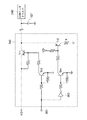
次に、上記ドライバ電源制御回路342について図12を参照して説明する。
ドライバ電源制御回路342は、ヘッドドライバと電源との間に介在され、更に、ヘッドドライバへ供給される電源を平滑するためのコンデンサ321と並列に接続されている。ドライバ電源制御回路342は、制御信号入力端361から入力される制御信号に応じてヘッドドライバへの電源を供給すると共に、この電源供給停止時には内蔵された放電用抵抗Rを介してコンデンサに充電されている電荷を放電させる。
【0062】
ドライバ電源制御回路342は、電源からヘッドドライバへの電源供給を制御するトランジスタTr1と、このトランジスタTr1の導通を制御するトランジスタTr3と、放電用抵抗Rと直列に接続され、コンデンサの電荷放電を制御するトランジスタTr2と、このトランジスタTr2の導通を制御するトランジスタTr4と、上記放電用抵抗Rからなる。上記トランジスタTr3のベースは制御信号入力端361に接続され、また、トランジスタTr4のベースはNOT回路363を介して制御信号入力端に接続されている。この制御信号入力端361にはCPU306aから制御信号が入力される。
【0063】
上記構成でなるドライバ電源制御回路342の動作について説明する。インクジェット式記録装置の主電源がONになっている状態において、ヘッドドライバに電源を供給する場合、CPU306aは制御信号入力端361に電源供給信号=“1”を与える。即ち、Hiの電圧を印加する。これにより、トランジスタTr3がONし、それによりトランジスタTr1がONとなる。電願からヘッドドライバに電源が供給される。この時、トランジスタTr4は、CPU306aから電源供給信号=“1”が与えられても、NOT回路363が配設されているためOFFとなり、それによりトランジスタTr2がOFFとなり、放電用抵抗Rとコンデンサとは非接続状態となる。
【0064】
次に、記録ヘッドにおいて、インク漏れが生じた場合のドライバ電源制御回路342の動作について説明する。インクジェット式記録装置の主電源がOFFであるとき、または、インク漏れ検出回路220が検出したインク漏れ検出用電極200の両電極間の電位差が所定の閾値(2.5V)よりも小さくなった場合、即ち、両電極が導通して電位差が下がった場合、この検出結果を示す信号がインク漏れ検出回路220からCPU306aに送られる。この信号に基づいて、CPU306aは制御信号入力端361に電源供給信号=“0”を与える。即ち、Lowの電圧を印加する。これにより、トランジスタTr3がOFFし、それによりトランジスタTr1がOFFとなり、電源からヘッドドライバへの電源供給が停止される。この時、トランジスタTr4には、CPU306aから制御信号入力端361に電源供給信号=“0”が与えられており、NOT回路363によってONとなり、それによりトランジスタTr2がONとなり、放電用抵抗Rとコンデンサが接続された状態となる。従って、コンデンサに充電されている電荷が放電用抵抗Rによって短時間で放電される。
【0065】
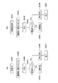
図13(a)及び(b)は、本実施形態におけるインク漏れ検出処理の流れを示すフローチャートである。
【0066】
まず、図13(a)に示すように、記録装置の主電源がONされると(S401)、インク漏れ検出用電極パターン200の外側電極200Aと内側電極200B間に所定の電圧(例えば、3.3V)を印加する(S402)。この外側電極200Aと内側電極200B間の電圧(電位差)は、インク漏れ検出回路220により検出され(S403)、問題が有るか否かが判断される。即ち、例えば、この電位差が所定の閾値(例えば、2.5V)を下回っているか否かが判断され(S404)、下回っていなければ(S404でNo)、印刷待機状態に移行する(S405)。一方、下回っていれば(S404でYes)、LED344を点滅等させてユーザに警告を表示して(S406)、終了する(S407)。
尚、図13(a)には図示しないが、ユーザに警告を表示する前又は後に、上述したように、電源からヘッドドライバ307への電源供給を停止する処理を実行しても良い。
【0067】
次に、図13(b)に示すように、図9には示さないホストコンピュータ上のプリンタドライバから印刷開始命令を受信すると(S501)、インク漏れ検出用電極パターン200の外側電極200Aと内側電極200B間に所定の電圧(例えば、3.3V)を印加する(S502)。この外側電極200Aと内側電極200B間の電圧(電位差)は、インク漏れ検出回路220により検出され(S503)、問題が有るか否かが判断される。即ち、例えば、この電位差が所定の閾値(例えば、2.5V)を下回っているか否かが判断され(S504)、下回っていなければ(S504でNo)、印刷を開始する(S505)。一方、下回っていれば(S504でYes)、LED344を点滅等させてユーザに警告を表示して(S506)、終了する(S507)。尚、図13(b)には図示しないが、ユーザに警告を表示する前又は後に、上述したように、電源からヘッドドライバ307への電源供給を停止する処理を実行しても良い。
【0068】
以上、本発明を特定の実施形態について述べたが、本発明はこれらに限られるものではなく、特許請求の範囲に記載した範囲内で他の実施形態についても適用される。
【0069】
例えば、上記実施形態では、圧力発生ユニット(アクチュエータ)と、供給孔プレート(Sプレート)と、リザーバプレート(Rプレート)と、ノズルプレート(Nプレート)とが積層された記録ヘッドについて本発明を適用したが、かかる積層型の記録ヘッド以外の記録ヘッドに関しても本発明は適用可能である。
【0070】
また、上記実施形態では、インク漏れ検出用電極パターン200の外側電極200Aと内側電極200B間の電位差によりインク漏れを検出したが、インク漏れ検出用の一対の電極間の電気的値の変化によりインク漏れを検出し得れば良く、この電気的値は、電圧値(電位差)に限られない。両電極間の抵抗値の変化又は電流値の変化によりインク漏れを検出しても良い。
【0071】
更に、上記実施形態では、インク漏れ検出用の一対の電極をアクチュエータ部材の振動板の縁部に複数の圧電素子を取り囲むように設けたが、アクチュエータ部材の振動板の表面に複数の圧電素子と共に設けてさえいれば、記録ヘッド内のインク漏れを検出し得る。
【0072】
尚、上記実施形態では、インク漏れ検出用の一対の電極間にスリットが形成されているが、かかるスリットが無くとも、記録ヘッド内のインク漏れを検出し得るのは勿論である。
【0073】
また、上記実施形態では、圧力発生素子としてはピエゾ素子を用いたが、ピエゾ素子に限らず、磁歪素子等を用いるものでもよい。
【0074】
【発明の効果】
本発明によれば、インクジェット式記録ヘッド内のインク漏れ、例えば、セグメントショート等を検出することができる。従って、記録ヘッド内のインク漏れによるインクジェット式記録ヘッドひいてはインクジェット式記録装置の故障を防止し得る。
【図面の簡単な説明】
【図1】本発明の実施形態に係るインクジェット式記録装置の要部を示す斜視図である。
【図2】図1に示すヘッドユニットを略示す一部断面図である。
【図3】図2に示す記録ヘッド102の分解斜視図である。
【図4】図3に示す記録ヘッド102の断面図である。
【図5】記録ヘッドの圧力発生ユニット(アクチュエータ)20と流路ユニット40の一部を示す分解斜視図である。
【図6】記録ヘッド102の製造工程を示す図である。
【図7】アクチュエータ20、20、20をそのインク漏れ検出用電極パターン200と共に拡大して示す模式図である。
【図8】図7のインク漏れ検出用電極パターン200の一部を、更に拡大して示す図である。
【図9】本発明の実施形態に係るインクジェット式記録装置の機能ブロック図である。
【図10】一例としてのインク漏れを生じた場合のアクチュエータを示す図である。
【図11】他の一例としてのインク漏れを生じた場合のインク漏れ検出用電極パターン間の様子を拡大して示す図である。
【図12】ヘッドドライバ電源制御回路を示す図である。
【図13】(a)及び(b)は、本実施形態におけるインク漏れ検出処理の流れを示すフローチャートである。
【符号の説明】
1 連通路基板
2 圧力室形成基板
3 圧力室
4 振動板
5 下部電極
6 圧電素子
9 連通路
11 ノズルプレート(Nプレート)
12 リザーバプレート(Rプレート)
13 供給孔プレート(Sプレート)
14 インク供給孔
15 インクリザーバ室
16 ノズル
18 インク導入口
20 圧力発生ユニット(アクチュエータ)
40 流路ユニット
90 ケースヘッド
100 ヘッドユニット
102 インクジェット式記録ヘッド
110 キャリッジ機構
120 紙送り機構
P 記録用紙
150 インクカートリッジ
200 一対のインク漏れ検出用電極パターン
200A 外側電極
200B 内側電極
202 スリット
LEAK 一点鎖線で示す部分
220 インク漏れ検出回路[0001]
TECHNICAL FIELD OF THE INVENTION
The present invention relates to an ink-jet recording apparatus such as an ink-jet printer or an ink-jet plotter, and more particularly to a technique for detecting ink leakage in a recording head that discharges and records ink droplets while moving.
[0002]
[Prior art]
2. Description of the Related Art There are various types of recording devices used in printers, facsimile machines and the like, such as a thermal type, a wire dot type, and an ink jet type. In particular, ink jet recording apparatuses have been widely used in recent years because recording speed is high and full color printing is easy. In this ink jet recording apparatus, an ink cartridge filled with ink is attached to a recording head, and the ink is supplied from the ink cartridge to the recording head. Then, printing is performed by discharging minute ink droplets from a plurality of nozzles provided in the print head onto the print medium. There are various methods for ejecting ink, and a method of ejecting ink droplets using flexural vibration of a pressure generating element such as a piezoelectric element makes it easy to control the particle diameter of the ejected ink droplet. In recent years, it has become a prominent method because it is superior in terms of high image quality. In this method, for example, a pressure generating element composed of a piezo element is stretched on a diaphragm constituting a part of the pressure generating chamber, and the volume of the pressure generating chamber is changed by bending vibration of the piezo element to eject ink droplets. Things.
[0003]
[Problems to be solved by the invention]
By the way, in the above-described ink jet recording head, ink leakage may occur during the process of supplying ink from the ink cartridge to the recording head. In such a case, due to a short circuit between the electrodes or the like, ink droplets are ejected from non-printing nozzles on the recording data, and a desired printing result cannot be obtained. In that case, it is possible that smoke is emitted.
[0004]
Hitherto, as an ink jet type recording head or recording apparatus which has taken such measures against ink leakage, those described in JP-A-10-193588 and JP-A-10-86357 have been proposed.
[0005]
However, in the conventional example described in Japanese Patent Application Laid-Open No. 10-193588, an ink jet recording head in which the ink cartridge (ink tank) can be replaced for each head is provided outside the recording head in order to obtain electrical contact with the recording apparatus main body. It is a configuration that detects ink leakage that has occurred in the pad portion exposed and provided to the pad, and particularly detects when a short circuit or the like occurs between the power pad through which a large current flows and another pad. It is targeted. Further, the conventional example described in Japanese Patent Application Laid-Open No. 10-86357 also has a configuration in which ink leakage occurring between driver driving power supply electrodes provided on a flexible substrate or the like outside the recording head is detected. The present invention relates to a technique for preventing a short circuit or smoking between electrodes to which a high voltage is applied.
[0006]
That is, the above conventional example is configured to detect ink leakage at an electrical contact provided on the recording head for electrical contact with an external member or the like. Only leaks can be detected. In other words, it is not possible to detect ink leakage in the recording head, for example, a segment short or the like.
As described above, the above-described conventional example does not show a configuration for detecting ink leakage occurring inside the print head, particularly regarding a print head using a flexural vibration of the pressure generating element described above. Was.
[0007]
Therefore, with respect to the recording head using the flexural vibration of the pressure generating element, even when a slight ink leak occurs inside the recording head, the ink leakage is detected and the non-printing is caused by a short circuit between the electrodes constituting the pressure generating element. There is a demand for a technique capable of preventing a situation such as an ink droplet being ejected from a printing nozzle.
[0008]
Therefore, an object of the present invention is to detect a case where ink leakage occurs inside a recording head of a system utilizing the flexural vibration of a pressure generating element, and to obtain an undesirable printing result due to a short circuit between electrodes constituting the pressure generating element. It is an object of the present invention to provide an ink jet type recording apparatus capable of preventing a situation such as occurrence of ink leakage, and a method of detecting ink leakage thereof.
[0009]
[Means for Solving the Problems]
In order to solve the above problem, in the present invention, a pair of electrodes for detecting ink leakage are provided together with a pressure generating element in a print head, an electrical value between the two electrodes is detected, and the value exceeds a predetermined threshold. In this way, ink leakage in the recording head is detected.
[0010]
That is, according to a first aspect of the present invention, a print head including a pressure generating element that is provided corresponding to a plurality of nozzles and applies pressure to ink is provided, and a drive signal is supplied to the pressure generating element of the print head. An ink jet recording apparatus that selectively drives at a predetermined recording timing by ejecting ink droplets from corresponding nozzles of the recording head to perform recording, wherein the ink provided together with the pressure generating element in the recording head An ink jet recording apparatus comprising: a pair of electrodes for detecting leakage; and a detecting means for detecting an electric value between the pair of electrodes is obtained.
[0011]
According to such a configuration, it is possible to detect an electric value between the pair of electrodes and detect an ink leak in the recording head when the value exceeds a predetermined threshold.
[0012]
Further, a control means for displaying a predetermined warning when the detection means detects that the electric value exceeds a predetermined threshold value may be provided.
[0013]
According to such a configuration, by performing the predetermined warning display, the user can prevent a situation such as producing an undesirable print result.
[0014]
Further, according to the second aspect of the present invention, a plurality of pressure chambers, a diaphragm for sealing one surface of these pressure chambers, and a lower portion disposed on an outer surface of the diaphragm corresponding to the pressure chambers An ink-jet type having an actuator formed by firing an electrode, the pressure-generating element laminated in close contact with these lower electrodes, and an upper electrode disposed so as to sandwich the pressure-generating element with the lower electrode; In the recording apparatus, there is provided an ink jet recording apparatus comprising: a pair of electrodes for detecting ink leakage formed by baking; and detecting means for detecting an electric value between the pair of electrodes.
[0015]
According to this configuration, an electrical value between the pair of electrodes for detecting ink leakage formed by firing is detected, and when the value exceeds a predetermined threshold value, the ink leakage near the pressure generating element in the recording head is detected. Can be detected.
[0016]
Further, the control means may be configured to cut off the power supply to the recording head instead of or in addition to the predetermined warning display.
[0017]
As a result, it is possible to reliably prevent a situation in which an undesired print result is generated, regardless of the user's response.
[0018]
The electric value may be any of a voltage value (potential difference), a resistance value, and a current value.
[0019]
Further, it is preferable that the pair of electrodes for detecting ink leakage is provided at an edge of the diaphragm of the actuator member so as to surround the plurality of pressure generating elements.
[0020]
Thereby, it is possible to protect the pressure generating element from ink leakage occurring on the actuator member.
[0021]
Further, it is desirable that the pair of electrodes for detecting ink leakage be integrally formed with the actuator member by firing.
[0022]
This facilitates manufacturing and minimizes cost increases.
[0023]
Preferably, a slit is formed between the pair of electrodes for detecting ink leakage of the actuator member.
[0024]
With such a configuration, the detection accuracy of ink leakage can be improved by the capillary force of the slit.
[0025]
According to a third aspect of the present invention, there is further provided a recording head including a pressure generating element which is provided corresponding to each of the plurality of nozzles and applies pressure to the ink, and the recording head usually includes the pressure generating element together with the pressure generating element. At this time, a pair of electrodes for detecting ink leakage in an open state is provided, the pressure generating element is selectively driven at a predetermined recording timing by a drive signal, and the ink is ejected from the corresponding nozzle as an ink droplet. In the method for detecting ink leakage of an ink jet recording apparatus for performing recording, a step of applying a voltage between the pair of electrodes for detecting the ink leakage, a step of measuring a change in the voltage, and the recording head according to a measurement result Detecting an ink leak in the ink cartridge.
[0026]
According to such a configuration, it is possible to measure a voltage change between the pair of electrodes and detect ink leakage in the print head depending on the value.
[0027]
The above steps may be performed both when the power of the ink jet recording apparatus is turned on and when the print start command is received.
[0028]
This makes it possible to detect ink leakage more reliably.
[0029]
BEST MODE FOR CARRYING OUT THE INVENTION
With reference to the drawings, an ink jet recording apparatus according to an embodiment of the present invention and an ink leakage detection method thereof will be described.
[0030]
The embodiment described below is a preferred specific example of the present invention, and thus various technically preferable limitations are given. However, the scope of the present invention particularly limits the present invention in the following description. The embodiments are not limited to these embodiments unless otherwise described.
[0031]
FIG. 1 is a perspective view showing a main part of an ink jet recording apparatus according to an embodiment of the present invention.
[0032]
As shown in FIG. 1, the ink jet recording apparatus of the present embodiment includes a
[0033]
The
[0034]
The
[0035]
The
[0036]
FIG. 2 is a partial sectional view schematically showing the
[0037]
FIG. 3 is an exploded perspective view of the
[0038]
As shown in FIG. 3, the ink
[0039]
In the
[0040]
As shown in FIGS. 3, 4, and 5, in the present embodiment, the
[0041]
As shown in FIGS. 3, 4, and 5, the
[0042]
As a joining method, a paste adhesive is applied by a screen printing method, a transfer method, or the like, and is cured by heating. It is also possible to use a film-shaped adhesive formed by pressing or the like. In this case, as the bonding method, the pressed film-form adhesive is laminated while being positioned using a guide hole (not shown), and then heated and pressed.
[0043]
The pressure generating unit (actuator) 20 is integrally formed by firing. First, a general process is shown in FIGS. In FIG. 6A, the
[0044]
As shown in FIG. 3, the supply hole plate (S plate) 13 is provided with
[0045]
FIG. 7 is a schematic diagram showing the
[0046]
As shown in FIG. 7, a pair of ink leakage
[0047]
As shown in FIG. 7, in each of the
[0048]
Further, in the ink jet recording head of this embodiment, as shown in FIG. 8, between the
[0049]
Next, the configuration of a control system of the ink jet recording apparatus of the present embodiment will be described with reference to FIG.
[0050]
FIG. 9 is a functional block diagram illustrating the overall configuration of the ink jet recording apparatus according to the present embodiment. In FIG. 9, the ink jet recording apparatus according to the present embodiment is schematically constituted by a
[0051]
In this embodiment, a head driver power
[0052]
The print data including the multi-level hierarchy information sent from the host computer or the like is held in the
[0053]
When print image data corresponding to one scan of the
[0054]
The
[0055]
The
[0056]
Here, the recording data SI controls the operation of the
[0057]
On the other hand, the print (head)
[0058]
Here, the operation and effect of the ink jet recording apparatus of the present embodiment will be described with reference to FIGS. FIG. 10 is a diagram illustrating an actuator when ink leakage occurs as an example. FIG. 11 is an enlarged view showing a state between electrode patterns for detecting ink leakage when ink leakage occurs as another example.
[0059]
In the ink jet recording apparatus according to the present embodiment, as shown in FIG. 10, when ink (shown by hatching) leaks on the
[0060]
When the result of the detection is output from the ink
[0061]
Next, the driver power
The driver power
[0062]
The driver power
[0063]
The operation of the driver power
[0064]
Next, the operation of the driver power
[0065]
FIGS. 13A and 13B are flowcharts illustrating the flow of the ink leak detection process according to the present embodiment.
[0066]
First, as shown in FIG. 13A, when the main power of the printing apparatus is turned on (S401), a predetermined voltage (for example, 3) is applied between the
Although not shown in FIG. 13A, the process of stopping the power supply from the power supply to the
[0067]
Next, as shown in FIG. 13B, when a print start command is received from a printer driver on the host computer not shown in FIG. 9 (S501), the
[0068]
As described above, the present invention has been described with respect to the specific embodiments. However, the present invention is not limited to these, and may be applied to other embodiments within the scope described in the claims.
[0069]
For example, in the above embodiment, the present invention is applied to a recording head in which a pressure generating unit (actuator), a supply hole plate (S plate), a reservoir plate (R plate), and a nozzle plate (N plate) are stacked. However, the present invention is also applicable to print heads other than such a stacked print head.
[0070]
In the above embodiment, the ink leakage is detected by the potential difference between the
[0071]
Further, in the above-described embodiment, the pair of electrodes for detecting ink leakage are provided on the edge of the diaphragm of the actuator member so as to surround the plurality of piezoelectric elements, but together with the plurality of piezoelectric elements on the surface of the diaphragm of the actuator member. As long as it is provided, ink leakage in the recording head can be detected.
[0072]
In the above embodiment, the slit is formed between the pair of electrodes for detecting ink leakage. However, it is needless to say that the ink leakage in the recording head can be detected without the slit.
[0073]
Further, in the above embodiment, a piezo element is used as the pressure generating element. However, the pressure generating element is not limited to the piezo element, and a magnetostrictive element may be used.
[0074]
【The invention's effect】
According to the present invention, it is possible to detect ink leakage in an ink jet recording head, for example, a segment short or the like. Therefore, it is possible to prevent the ink jet recording head and the ink jet recording apparatus from malfunctioning due to ink leakage in the recording head.
[Brief description of the drawings]
FIG. 1 is a perspective view showing a main part of an ink jet recording apparatus according to an embodiment of the present invention.
FIG. 2 is a partial cross-sectional view schematically showing the head unit shown in FIG.
FIG. 3 is an exploded perspective view of the
FIG. 4 is a sectional view of the
FIG. 5 is an exploded perspective view showing a part of a pressure generating unit (actuator) 20 and a
FIG. 6 is a diagram illustrating a manufacturing process of the
FIG. 7 is an enlarged schematic
8 is a diagram showing a part of an ink leakage
FIG. 9 is a functional block diagram of the ink jet recording apparatus according to the embodiment of the present invention.
FIG. 10 is a diagram illustrating an actuator when ink leakage occurs as an example.
FIG. 11 is an enlarged view showing a state between electrode patterns for detecting ink leakage when another example of ink leakage occurs.
FIG. 12 is a diagram showing a head driver power supply control circuit.
FIGS. 13A and 13B are flowcharts illustrating a flow of an ink leak detection process according to the present embodiment.
[Explanation of symbols]
1 Communication passage board
2 Pressure chamber forming substrate
3 pressure chamber
4 diaphragm
5 Lower electrode
6 Piezoelectric element
9 connecting passage
11 Nozzle plate (N plate)
12 Reservoir plate (R plate)
13 Supply hole plate (S plate)
14 Ink supply hole
15 Incubator room
16 nozzles
18 Ink inlet
20 Pressure generating unit (actuator)
40 channel unit
90 case head
100 head unit
102 inkjet recording head
110 Carriage mechanism
120 Paper feed mechanism
P Recording paper
150 ink cartridge
200 Pair of Ink Leak Detection Electrode Patterns
200A outer electrode
200B inner electrode
202 slit
LEAK Portion indicated by dashed line
220 Ink leak detection circuit
Claims (18)
前記記録ヘッド内に前記圧力発生素子と共に設けたインク漏れ検出用の一対の電極と、前記一対の電極間の電気的値を検出する検出手段とを有することを特徴とするインクジェット式記録装置。A recording head including a pressure generating element for applying pressure to ink, the recording head including a pressure generating element for applying pressure to ink, and selectively driving the pressure generating element of the recording head at a predetermined recording timing by a driving signal; An ink jet recording apparatus that performs recording by discharging ink droplets from corresponding nozzles of a recording head,
An ink jet recording apparatus comprising: a pair of electrodes for detecting ink leakage provided together with the pressure generating element in the recording head; and a detecting unit for detecting an electric value between the pair of electrodes.
前記インク漏れ検出用の一対の電極間に電圧を印加する工程と、
該電圧の変化を測定する工程と、
測定結果に応じて前記記録ヘッド内のインク漏れを検出する工程とを有することを特徴とするインク漏れ検出方法。A print head including a pressure generating element that is provided corresponding to the plurality of nozzles and applies pressure to the ink is provided, and a pair of the ink leak detection that is normally open with the pressure generating element in the print head. An ink leak detection method for an ink jet recording apparatus for providing an electrode, selectively driving the pressure generating element at a predetermined recording timing according to a driving signal, and discharging the ink as ink droplets from the corresponding nozzle to perform recording. ,
Applying a voltage between the pair of electrodes for detecting ink leakage,
Measuring the change in voltage;
Detecting an ink leak in the recording head according to the measurement result.
Priority Applications (1)
| Application Number | Priority Date | Filing Date | Title |
|---|---|---|---|
| JP2002224283A JP2004058633A (en) | 2002-07-31 | 2002-07-31 | Inkjet recorder and its ink leakage detecting method |
Applications Claiming Priority (1)
| Application Number | Priority Date | Filing Date | Title |
|---|---|---|---|
| JP2002224283A JP2004058633A (en) | 2002-07-31 | 2002-07-31 | Inkjet recorder and its ink leakage detecting method |
Publications (1)
| Publication Number | Publication Date |
|---|---|
| JP2004058633A true JP2004058633A (en) | 2004-02-26 |
Family
ID=31943807
Family Applications (1)
| Application Number | Title | Priority Date | Filing Date |
|---|---|---|---|
| JP2002224283A Pending JP2004058633A (en) | 2002-07-31 | 2002-07-31 | Inkjet recorder and its ink leakage detecting method |
Country Status (1)
| Country | Link |
|---|---|
| JP (1) | JP2004058633A (en) |
Cited By (11)
| Publication number | Priority date | Publication date | Assignee | Title |
|---|---|---|---|---|
| US7163274B2 (en) | 2003-12-29 | 2007-01-16 | Industrial Technology Research Institute | Inkjet dispensing apparatus |
| JP2007021854A (en) * | 2005-07-14 | 2007-02-01 | Brother Ind Ltd | Inkjet head and its inspection method |
| JP2007021855A (en) * | 2005-07-14 | 2007-02-01 | Brother Ind Ltd | Inkjet head and its inspection method |
| JP2008018599A (en) * | 2006-07-12 | 2008-01-31 | Ricoh Co Ltd | Image forming apparatus |
| US7828350B2 (en) | 2007-07-17 | 2010-11-09 | Denso Corporation | Vehicular collision detection apparatus |
| JP2015066766A (en) * | 2013-09-27 | 2015-04-13 | ブラザー工業株式会社 | Liquid discharge head |
| US9682546B2 (en) | 2014-11-21 | 2017-06-20 | Canon Kabushiki Kaisha | Liquid discharging substrate, printhead, and printing apparatus |
| JP2018192810A (en) * | 2018-09-12 | 2018-12-06 | キヤノン株式会社 | Recording device and control method therefor |
| JP2019072905A (en) * | 2017-10-16 | 2019-05-16 | エスアイアイ・プリンテック株式会社 | Liquid jet head and liquid jet recording device |
| US10328710B2 (en) | 2017-05-15 | 2019-06-25 | Seiko Epson Corporation | Recording apparatus |
| US10406837B2 (en) | 2014-03-26 | 2019-09-10 | Canon Kabushiki Kaisha | Printing apparatus and leakage detection method of the same |
-
2002
- 2002-07-31 JP JP2002224283A patent/JP2004058633A/en active Pending
Cited By (13)
| Publication number | Priority date | Publication date | Assignee | Title |
|---|---|---|---|---|
| US7163274B2 (en) | 2003-12-29 | 2007-01-16 | Industrial Technology Research Institute | Inkjet dispensing apparatus |
| JP4678502B2 (en) * | 2005-07-14 | 2011-04-27 | ブラザー工業株式会社 | Ink jet head and inspection method thereof |
| JP2007021854A (en) * | 2005-07-14 | 2007-02-01 | Brother Ind Ltd | Inkjet head and its inspection method |
| JP2007021855A (en) * | 2005-07-14 | 2007-02-01 | Brother Ind Ltd | Inkjet head and its inspection method |
| JP4678503B2 (en) * | 2005-07-14 | 2011-04-27 | ブラザー工業株式会社 | Ink jet head and inspection method thereof |
| JP2008018599A (en) * | 2006-07-12 | 2008-01-31 | Ricoh Co Ltd | Image forming apparatus |
| US7828350B2 (en) | 2007-07-17 | 2010-11-09 | Denso Corporation | Vehicular collision detection apparatus |
| JP2015066766A (en) * | 2013-09-27 | 2015-04-13 | ブラザー工業株式会社 | Liquid discharge head |
| US10406837B2 (en) | 2014-03-26 | 2019-09-10 | Canon Kabushiki Kaisha | Printing apparatus and leakage detection method of the same |
| US9682546B2 (en) | 2014-11-21 | 2017-06-20 | Canon Kabushiki Kaisha | Liquid discharging substrate, printhead, and printing apparatus |
| US10328710B2 (en) | 2017-05-15 | 2019-06-25 | Seiko Epson Corporation | Recording apparatus |
| JP2019072905A (en) * | 2017-10-16 | 2019-05-16 | エスアイアイ・プリンテック株式会社 | Liquid jet head and liquid jet recording device |
| JP2018192810A (en) * | 2018-09-12 | 2018-12-06 | キヤノン株式会社 | Recording device and control method therefor |
Similar Documents
| Publication | Publication Date | Title |
|---|---|---|
| US7901034B2 (en) | Image forming device for performing idle discharge | |
| US6488354B2 (en) | Liquid jetting apparatus | |
| US20120249638A1 (en) | Liquid ejecting apparatus and control method thereof | |
| CN107867071B (en) | Liquid ejecting apparatus, control program for liquid ejecting apparatus, recording medium, and flushing adjusting method | |
| JP2015037863A (en) | Liquid jet apparatus, and control method for the same | |
| US9259929B2 (en) | Liquid ejecting apparatus and control method of liquid ejecting head | |
| JP2004058633A (en) | Inkjet recorder and its ink leakage detecting method | |
| JP2009066948A (en) | Liquid jetting apparatus | |
| JP4266568B2 (en) | DRIVE DEVICE, LIQUID DISCHARGE DEVICE, AND DRIVE METHOD | |
| JP2012171308A (en) | Liquid ejection device and method for driving the same | |
| JP2010131979A (en) | Liquid injection device, and method of controlling the same | |
| US20190389201A1 (en) | Method of controlling liquid ejecting apparatus and liquid ejecting apparatus | |
| JP6451109B2 (en) | Liquid ejection device and method for controlling liquid ejection device | |
| JP2016150487A (en) | Liquid injection device | |
| JP2016007789A (en) | Ink jet printer and control method of the same | |
| JP2017113965A (en) | Liquid discharge device and liquid discharge method | |
| JP6471797B2 (en) | Liquid ejector | |
| JP2007268893A (en) | Liquid droplet discharge device | |
| JP4956901B2 (en) | Liquid ejector | |
| JP2021014047A (en) | Liquid discharge head and recording device | |
| JP2001315355A (en) | Ink jet head and ink jet printer | |
| JP2019199056A (en) | Liquid jet device and driving method for the same | |
| JP4259741B2 (en) | Inkjet recording apparatus and image forming apparatus | |
| US20220234344A1 (en) | Liquid ejection apparatus | |
| JP2004195792A (en) | Ink jet recording device |