JP2015223762A - Liquid injection device, control method of liquid injection head and control method of liquid injection device - Google Patents
Liquid injection device, control method of liquid injection head and control method of liquid injection device Download PDFInfo
- Publication number
- JP2015223762A JP2015223762A JP2014109721A JP2014109721A JP2015223762A JP 2015223762 A JP2015223762 A JP 2015223762A JP 2014109721 A JP2014109721 A JP 2014109721A JP 2014109721 A JP2014109721 A JP 2014109721A JP 2015223762 A JP2015223762 A JP 2015223762A
- Authority
- JP
- Japan
- Prior art keywords
- nozzle
- liquid
- pressure chamber
- actuator
- ink
- Prior art date
- Legal status (The legal status is an assumption and is not a legal conclusion. Google has not performed a legal analysis and makes no representation as to the accuracy of the status listed.)
- Pending
Links
Images


Classifications
-
- B—PERFORMING OPERATIONS; TRANSPORTING
- B41—PRINTING; LINING MACHINES; TYPEWRITERS; STAMPS
- B41J—TYPEWRITERS; SELECTIVE PRINTING MECHANISMS, i.e. MECHANISMS PRINTING OTHERWISE THAN FROM A FORME; CORRECTION OF TYPOGRAPHICAL ERRORS
- B41J2/00—Typewriters or selective printing mechanisms characterised by the printing or marking process for which they are designed
- B41J2/005—Typewriters or selective printing mechanisms characterised by the printing or marking process for which they are designed characterised by bringing liquid or particles selectively into contact with a printing material
- B41J2/01—Ink jet
- B41J2/015—Ink jet characterised by the jet generation process
- B41J2/04—Ink jet characterised by the jet generation process generating single droplets or particles on demand
- B41J2/045—Ink jet characterised by the jet generation process generating single droplets or particles on demand by pressure, e.g. electromechanical transducers
- B41J2/04501—Control methods or devices therefor, e.g. driver circuits, control circuits
- B41J2/04588—Control methods or devices therefor, e.g. driver circuits, control circuits using a specific waveform
-
- B—PERFORMING OPERATIONS; TRANSPORTING
- B41—PRINTING; LINING MACHINES; TYPEWRITERS; STAMPS
- B41J—TYPEWRITERS; SELECTIVE PRINTING MECHANISMS, i.e. MECHANISMS PRINTING OTHERWISE THAN FROM A FORME; CORRECTION OF TYPOGRAPHICAL ERRORS
- B41J2/00—Typewriters or selective printing mechanisms characterised by the printing or marking process for which they are designed
- B41J2/005—Typewriters or selective printing mechanisms characterised by the printing or marking process for which they are designed characterised by bringing liquid or particles selectively into contact with a printing material
- B41J2/01—Ink jet
- B41J2/015—Ink jet characterised by the jet generation process
- B41J2/04—Ink jet characterised by the jet generation process generating single droplets or particles on demand
- B41J2/045—Ink jet characterised by the jet generation process generating single droplets or particles on demand by pressure, e.g. electromechanical transducers
- B41J2/04501—Control methods or devices therefor, e.g. driver circuits, control circuits
- B41J2/0451—Control methods or devices therefor, e.g. driver circuits, control circuits for detecting failure, e.g. clogging, malfunctioning actuator
-
- B—PERFORMING OPERATIONS; TRANSPORTING
- B41—PRINTING; LINING MACHINES; TYPEWRITERS; STAMPS
- B41J—TYPEWRITERS; SELECTIVE PRINTING MECHANISMS, i.e. MECHANISMS PRINTING OTHERWISE THAN FROM A FORME; CORRECTION OF TYPOGRAPHICAL ERRORS
- B41J2/00—Typewriters or selective printing mechanisms characterised by the printing or marking process for which they are designed
- B41J2/005—Typewriters or selective printing mechanisms characterised by the printing or marking process for which they are designed characterised by bringing liquid or particles selectively into contact with a printing material
- B41J2/01—Ink jet
- B41J2/015—Ink jet characterised by the jet generation process
- B41J2/04—Ink jet characterised by the jet generation process generating single droplets or particles on demand
- B41J2/045—Ink jet characterised by the jet generation process generating single droplets or particles on demand by pressure, e.g. electromechanical transducers
- B41J2/04501—Control methods or devices therefor, e.g. driver circuits, control circuits
- B41J2/04581—Control methods or devices therefor, e.g. driver circuits, control circuits controlling heads based on piezoelectric elements
-
- B—PERFORMING OPERATIONS; TRANSPORTING
- B41—PRINTING; LINING MACHINES; TYPEWRITERS; STAMPS
- B41J—TYPEWRITERS; SELECTIVE PRINTING MECHANISMS, i.e. MECHANISMS PRINTING OTHERWISE THAN FROM A FORME; CORRECTION OF TYPOGRAPHICAL ERRORS
- B41J2/00—Typewriters or selective printing mechanisms characterised by the printing or marking process for which they are designed
- B41J2/005—Typewriters or selective printing mechanisms characterised by the printing or marking process for which they are designed characterised by bringing liquid or particles selectively into contact with a printing material
- B41J2/01—Ink jet
- B41J2/015—Ink jet characterised by the jet generation process
- B41J2/04—Ink jet characterised by the jet generation process generating single droplets or particles on demand
- B41J2/045—Ink jet characterised by the jet generation process generating single droplets or particles on demand by pressure, e.g. electromechanical transducers
- B41J2/04501—Control methods or devices therefor, e.g. driver circuits, control circuits
- B41J2/04586—Control methods or devices therefor, e.g. driver circuits, control circuits controlling heads of a type not covered by groups B41J2/04575 - B41J2/04585, or of an undefined type
-
- B—PERFORMING OPERATIONS; TRANSPORTING
- B41—PRINTING; LINING MACHINES; TYPEWRITERS; STAMPS
- B41J—TYPEWRITERS; SELECTIVE PRINTING MECHANISMS, i.e. MECHANISMS PRINTING OTHERWISE THAN FROM A FORME; CORRECTION OF TYPOGRAPHICAL ERRORS
- B41J2/00—Typewriters or selective printing mechanisms characterised by the printing or marking process for which they are designed
- B41J2/005—Typewriters or selective printing mechanisms characterised by the printing or marking process for which they are designed characterised by bringing liquid or particles selectively into contact with a printing material
- B41J2/01—Ink jet
- B41J2/135—Nozzles
- B41J2/165—Preventing or detecting of nozzle clogging, e.g. cleaning, capping or moistening for nozzles
- B41J2/16517—Cleaning of print head nozzles
- B41J2/1652—Cleaning of print head nozzles by driving a fluid through the nozzles to the outside thereof, e.g. by applying pressure to the inside or vacuum at the outside of the print head
- B41J2/16526—Cleaning of print head nozzles by driving a fluid through the nozzles to the outside thereof, e.g. by applying pressure to the inside or vacuum at the outside of the print head by applying pressure only
-
- B—PERFORMING OPERATIONS; TRANSPORTING
- B41—PRINTING; LINING MACHINES; TYPEWRITERS; STAMPS
- B41J—TYPEWRITERS; SELECTIVE PRINTING MECHANISMS, i.e. MECHANISMS PRINTING OTHERWISE THAN FROM A FORME; CORRECTION OF TYPOGRAPHICAL ERRORS
- B41J2/00—Typewriters or selective printing mechanisms characterised by the printing or marking process for which they are designed
- B41J2/005—Typewriters or selective printing mechanisms characterised by the printing or marking process for which they are designed characterised by bringing liquid or particles selectively into contact with a printing material
- B41J2/01—Ink jet
- B41J2/135—Nozzles
- B41J2/165—Preventing or detecting of nozzle clogging, e.g. cleaning, capping or moistening for nozzles
- B41J2/16579—Detection means therefor, e.g. for nozzle clogging
Abstract
Description
本発明は、インクジェット式記録装置などの液体噴射装置、これに搭載される液体噴射ヘッドの制御方法、および、液体噴射装置の制御方法に関し、特に、ノズルから液体を噴射させて液体噴射ヘッドの噴射能力を回復させるメンテナンス処理を行う液体噴射装置、液体噴射ヘッドの制御方法、および、液体噴射装置の制御方法に関するものである。 The present invention relates to a liquid ejecting apparatus such as an ink jet recording apparatus, a control method for a liquid ejecting head mounted thereon, and a control method for a liquid ejecting apparatus, and in particular, ejects liquid from a nozzle to eject the liquid ejecting head. The present invention relates to a liquid ejecting apparatus that performs maintenance processing for recovering capability, a liquid ejecting head control method, and a liquid ejecting apparatus control method.
液体噴射装置は液体噴射ヘッドを備え、この液体噴射ヘッドから各種の液体を噴射(吐出)する装置である。この液体噴射装置としては、例えば、インクジェット式プリンターやインクジェット式プロッター等の画像記録装置があるが、最近ではごく少量の液体を所定位置に正確に着弾させることができるという特長を活かして各種の製造装置にも応用されている。例えば、液晶ディスプレイ等のカラーフィルタを製造するディスプレイ製造装置,有機EL(Electro Luminescence)ディスプレイやFED(面発光ディスプレイ)等の電極を形成する電極形成装置,バイオチップ(生物化学素子)を製造するチップ製造装置に応用されている。そして、画像記録装置用の記録ヘッドでは液状のインクを噴射し、ディスプレイ製造装置用の色材噴射ヘッドではR(Red)・G(Green)・B(Blue)の各色材の溶液を噴射する。また、電極形成装置用の電極材噴射ヘッドでは液状の電極材料を噴射し、チップ製造装置用の生体有機物噴射ヘッドでは生体有機物の溶液を噴射する。 The liquid ejecting apparatus includes a liquid ejecting head and ejects (discharges) various liquids from the liquid ejecting head. As this liquid ejecting apparatus, for example, there are image recording apparatuses such as an ink jet printer and an ink jet plotter. Recently, various types of liquid ejecting apparatuses are utilized by utilizing the feature that a very small amount of liquid can be accurately landed on a predetermined position. It is also applied to devices. For example, a display manufacturing apparatus for manufacturing a color filter such as a liquid crystal display, an electrode forming apparatus for forming an electrode such as an organic EL (Electro Luminescence) display or FED (surface emitting display), a chip for manufacturing a biochip (biochemical element) Applied to manufacturing equipment. The recording head for the image recording apparatus ejects liquid ink, and the color material ejecting head for the display manufacturing apparatus ejects solutions of R (Red), G (Green), and B (Blue) color materials. The electrode material ejecting head for the electrode forming apparatus ejects a liquid electrode material, and the bioorganic matter ejecting head for the chip manufacturing apparatus ejects a bioorganic solution.
ここで、液体噴射ヘッドにおいてノズル内の液体に気泡が混入する場合がある。具体的には、例えば、体噴射ヘッドのノズルが形成された面に対して払拭部材(弾性部材からなるワイパー等)を摺動させて当該ノズル面を払拭して清浄化する際に、ノズル内の液体に気泡が入り込むことがある。また、記録媒体としての記録用紙から生じてノズル面に付着した微細な紙粉がノズル内に進入し、この紙粉を介してノズル内の液体に気泡が入り込む場合もある。さらに、ノズル付近の増粘した液体を噴射する際に気泡を液体内に巻き込む場合もある。 Here, there is a case where bubbles are mixed in the liquid in the nozzle in the liquid ejecting head. Specifically, for example, when a wiping member (such as a wiper made of an elastic member) is slid with respect to the surface of the body ejection head on which the nozzle is formed, the nozzle surface is wiped and cleaned. Bubbles may enter the liquid. In addition, fine paper dust generated from the recording paper as a recording medium and adhering to the nozzle surface may enter the nozzle, and bubbles may enter the liquid in the nozzle through the paper dust. Furthermore, when jetting the thickened liquid in the vicinity of the nozzle, bubbles may be involved in the liquid.
この種の液体噴射ヘッドを搭載する液体噴射装置では、液体噴射ヘッドのノズル内や圧力室内の気泡あるいは増粘液体を排出するために、記録媒体等の着弾対象に対する液体の噴射処理、すなわち、液体噴射装置が本来目的とする噴射処理とは別に、ノズルから液体を強制的に噴射させるフラッシングと呼ばれるメンテナンス処理が行われている(例えば、特許文献1)。このフラッシング処理では、駆動波形をアクチュエーターに印加して当該アクチュエーターを駆動することで、ノズルに連通する圧力室内の液体に圧力変動を生じさせ、当該圧力変動を利用してノズルから液体を噴射(捨て撃ち或は空吐出ともいう)させる。この際、一般的には、最初に圧力室内を減圧することでノズル内のメニスカスを圧力室側に一旦引き込んだ後、圧力室内を急激に加圧することでメニスカスを圧力室側とは反対側(噴射側)に押し出して当該ノズルから液滴を噴射させている。このような動作を所定回数連続的に繰り返すことで、ノズルや圧力室内の増粘した液体を排出させている。 In a liquid ejecting apparatus equipped with this type of liquid ejecting head, in order to discharge bubbles or thickened liquid in nozzles or pressure chambers of the liquid ejecting head, a liquid ejecting process for a landing target such as a recording medium, that is, a liquid In addition to the jet process originally intended by the jet device, a maintenance process called flushing that forcibly jets liquid from the nozzle is performed (for example, Patent Document 1). In this flushing process, a drive waveform is applied to an actuator to drive the actuator, thereby causing a pressure fluctuation in the liquid in the pressure chamber communicating with the nozzle, and ejecting (discarding) the liquid from the nozzle using the pressure fluctuation. Shot or empty discharge). At this time, generally, the pressure chamber is first depressurized to first draw the meniscus in the nozzle into the pressure chamber side, and then the pressure chamber is rapidly pressurized so that the meniscus is opposite to the pressure chamber side ( The liquid droplets are ejected from the nozzle by being pushed out to the ejection side. By repeating such an operation continuously a predetermined number of times, the thickened liquid in the nozzle and the pressure chamber is discharged.
しかしながら、上記の従来のフラッシング処理では、ノズルにおける液体内の気泡を排出することが困難であった。すなわち、従来のフラッシング処理における最初の圧力室内の減圧時に気泡が圧力室側に移動してしまい、これにより、フラッシング処理を繰り返しても当該気泡を排出することが困難となっていた。 However, in the conventional flushing process, it is difficult to discharge bubbles in the liquid at the nozzle. That is, bubbles are moved to the pressure chamber side during the first pressure reduction in the conventional flushing process, and it is difficult to discharge the bubbles even if the flushing process is repeated.
本発明は、このような事情に鑑みてなされたものであり、その目的は、液体の無駄な消費を低減しつつ、ノズル内の液体における気泡を効率よく排出することが可能な液体噴射装置、液体噴射ヘッドの制御方法、および、液体噴射装置の制御方法を提供することにある。 The present invention has been made in view of such circumstances, and a purpose thereof is a liquid ejecting apparatus capable of efficiently discharging bubbles in the liquid in the nozzle while reducing wasteful consumption of the liquid, It is an object to provide a method for controlling a liquid ejecting head and a method for controlling a liquid ejecting apparatus.
本発明の液体噴射装置は、上記目的を達成するために提案されたものであり、ノズルに連通する圧力室、及び、該圧力室内の液体に圧力変動を生じさせるアクチュエーターを有し、当該アクチュエーターの作動によって前記ノズルから液体を噴射可能な液体噴射ヘッドと、
前記ノズルについて液体の噴射の異常を検出する検出機構と、
を備え、駆動波形によりアクチュエーターを駆動してメンテナンス処理を行うことが可能な液体噴射装置であって、
前記検出機構により異常が検出されたノズルに対応する前記アクチュエーターに前記駆動波形を複数回印加して噴射動作を行わせるメンテナンス処理において、少なくとも最初にアクチュエーターに印加される駆動波形は、前記ノズルにおけるメニスカスを初期位置から前記圧力室側に積極的に引き込むことなく前記噴射側に押し出して当該ノズルから液体を噴射させるメンテナンス駆動波形であることを特徴とする。
The liquid ejecting apparatus of the present invention has been proposed to achieve the above-described object, and includes a pressure chamber communicating with a nozzle and an actuator that causes a pressure fluctuation in the liquid in the pressure chamber. A liquid ejecting head capable of ejecting liquid from the nozzle by operation;
A detection mechanism for detecting an abnormality in liquid ejection for the nozzle;
A liquid ejecting apparatus capable of performing maintenance processing by driving an actuator with a drive waveform,
In the maintenance process in which the drive waveform is applied to the actuator corresponding to the nozzle in which the abnormality is detected by the detection mechanism to perform the ejection operation, the drive waveform applied to the actuator at least first is a meniscus in the nozzle. This is a maintenance drive waveform in which liquid is ejected from the nozzle by pushing out from the initial position to the ejection side without being actively pulled into the pressure chamber side.
本発明によれば、液体の無駄な消費を抑えつつノズル内部の液体内の気泡を排出することが可能となる。すなわち、異常が検出されたノズルに対してメンテナンス処理が行われることで、無駄なメンテナンス処理が行われることが抑制される。また、少なくとも最初に印加されるメンテナンス駆動波形による噴射動作においては、ノズルにおける液体内の気泡を圧力室側に浮上させにくいため、気泡をノズル内の液体と共に効率よく排出させることができる。これにより、従来のメンテナンス処理と比較して液体の消費を大幅に抑えることが可能となる。
なお、噴射動作とは、結果としてノズルから液体が実際に噴射されるか否かに拘わらず、駆動波形によりアクチュエーターを駆動して圧力室内にノズルから液体を噴射させる得る程度の圧力変動を生じさせるアクチュエーターの動作を意味する。
According to the present invention, it is possible to discharge bubbles in the liquid inside the nozzle while suppressing wasteful consumption of the liquid. That is, the maintenance process is performed on the nozzle in which the abnormality is detected, thereby suppressing the unnecessary maintenance process. Further, at least in the ejection operation by the maintenance drive waveform applied first, the bubbles in the liquid in the nozzle are difficult to float to the pressure chamber side, so that the bubbles can be efficiently discharged together with the liquid in the nozzle. As a result, it is possible to significantly reduce liquid consumption compared to conventional maintenance processing.
The ejection operation results in a pressure fluctuation that can cause the liquid to be ejected from the nozzle into the pressure chamber by driving the actuator with the drive waveform regardless of whether or not the liquid is actually ejected from the nozzle. It means the operation of the actuator.
上記構成において、前記メンテナンス処理において前記アクチュエーターに3回以上印加する駆動波形のうち、少なくとも1回目乃至3回目の駆動波形は、前記メンテナンス駆動波形である構成を採用することが望ましい。 In the above configuration, it is preferable that at least the first to third drive waveforms among the drive waveforms applied to the actuator three or more times in the maintenance process are the maintenance drive waveforms.
上記構成によれば、メンテナンス駆動波形を3回印加して噴射動作を行わせることで、ノズル内の気泡をより確実に排出させることができる。
According to the said structure, the bubble in a nozzle can be more reliably discharged | emitted by applying a
上記構成において、前記メンテナンス駆動波形は、前記液体噴射ヘッドにおいて噴射可能な最大の液量を噴射させる駆動波形である構成を採用することが望ましい。 In the above configuration, it is desirable that the maintenance drive waveform is a drive waveform that ejects a maximum amount of liquid that can be ejected by the liquid ejecting head.
上記構成によれば、一度により多くの液体をノズルから噴射させることができるとともに、微小な液滴を噴射させる駆動波形と比較して噴射動作時の圧力室内の圧力変化が穏やかであるため、圧力室内に不必要な振動を生じさせにくく、ノズルから気泡をより効率よく排出させることができる。 According to the above configuration, more liquid can be ejected from the nozzle at a time, and the pressure change in the pressure chamber during the ejection operation is gentle compared to the drive waveform that ejects minute droplets. It is difficult to cause unnecessary vibration in the room, and bubbles can be discharged from the nozzle more efficiently.
また、本発明は、ノズルに連通する圧力室、及び、該圧力室内の液体に圧力変動を生じさせるアクチュエーターを有し、駆動波形によりアクチュエーターを駆動させることによって前記ノズルから液体を噴射可能な液体噴射ヘッドの制御方法であって、
液体の噴射の異常が検出されたノズルに対応する前記アクチュエーターに前記駆動波形を複数回印加して噴射動作を行わせるメンテナンス処理において、前記ノズルにおけるメニスカスを初期位置から前記圧力室側に積極的に引き込むことなく前記噴射側に押し出して当該ノズルから液体を噴射させるメンテナンス駆動波形を前記アクチュエーターに少なくとも最初に印加することを特徴とする。
The present invention also includes a pressure chamber that communicates with a nozzle, and an actuator that causes a pressure fluctuation in the liquid in the pressure chamber, and the liquid ejection that can eject liquid from the nozzle by driving the actuator with a drive waveform. A head control method,
In a maintenance process in which the drive waveform is applied to the actuator corresponding to the nozzle in which the abnormality of liquid ejection is detected to perform the ejection operation, the meniscus in the nozzle is actively moved from the initial position to the pressure chamber side. A maintenance drive waveform for ejecting liquid to the ejection side without drawing in and ejecting liquid from the nozzle is applied to the actuator at least first.
さらに、本発明は、ノズルに連通する圧力室、及び、該圧力室内の液体に圧力変動を生じさせるアクチュエーターを有し、当該アクチュエーターの作動によって前記ノズルから液体を噴射可能な液体噴射ヘッドと、前記ノズルについて液体の噴射の異常を検出する検出機構と、を備え、駆動波形によりアクチュエーターを駆動させることによってメンテナンス処理を行うことが可能な液体噴射装置の制御方法であって、
液体の噴射の異常が検出されたノズルに対応する前記アクチュエーターに前記駆動波形を複数回印加して噴射動作を行わせるメンテナンス処理において、前記ノズルにおけるメニスカスを初期位置から前記圧力室側に積極的に引き込むことなく前記噴射側に押し出して当該ノズルから液体を噴射させるメンテナンス駆動波形を前記アクチュエーターに少なくとも最初に印加することを特徴する。
The present invention further includes a pressure chamber communicating with the nozzle, and an actuator that causes a pressure fluctuation in the liquid in the pressure chamber, and a liquid ejecting head capable of ejecting the liquid from the nozzle by the operation of the actuator; A control mechanism for a liquid ejecting apparatus capable of performing a maintenance process by driving an actuator with a drive waveform, and a detection mechanism that detects an abnormality in ejecting liquid with respect to a nozzle,
In a maintenance process in which the drive waveform is applied to the actuator corresponding to the nozzle in which the abnormality of liquid ejection is detected to perform the ejection operation, the meniscus in the nozzle is actively moved from the initial position to the pressure chamber side. A maintenance drive waveform for ejecting liquid from the nozzle by pushing out to the ejection side without drawing is applied to the actuator at least first.
以下、本発明を実施するための形態を、添付図面を参照して説明する。なお、以下に述べる実施の形態では、本発明の好適な具体例として種々の限定がされているが、本発明の範囲は、以下の説明において特に本発明を限定する旨の記載がない限り、これらの態様に限られるものではない。また、以下においては、本発明の液体噴射装置として、インクジェット式記録装置(以下、プリンター)を例に挙げて説明する。 DESCRIPTION OF EMBODIMENTS Hereinafter, embodiments for carrying out the present invention will be described with reference to the accompanying drawings. In the embodiments described below, various limitations are made as preferred specific examples of the present invention. However, the scope of the present invention is not limited to the following description unless otherwise specified. However, the present invention is not limited to these embodiments. In the following, an ink jet recording apparatus (hereinafter referred to as a printer) will be described as an example of the liquid ejecting apparatus of the invention.
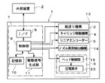
図1は、プリンター1の内部構成を説明する正面図、図2は、プリンター1の電気的な構成を説明するブロック図である。本実施形態におけるプリンター1は、例えばコンピューター等の電子機器等の外部装置2と無線又は有線で電気的に接続されており、この外部装置2から記録用紙等の記録媒体(液体の着弾対象)に画像やテキストを印刷させるため、その画像等に応じた印刷データを受信する。このプリンター1は、プリンターコントローラー7とプリントエンジン13とを有している。液体噴射ヘッドの一種である記録ヘッド6は、インクカートリッジ17(液体供給源)を搭載したキャリッジ16の底面側に取り付けられている。そして、当該キャリッジ16は、キャリッジ移動機構4によってガイドロッド18に沿って往復移動可能に構成されている。すなわち、プリンター1は、紙送り機構3によって記録媒体をプラテン12上に順次搬送すると共に、記録ヘッド6を記録媒体の幅方向(主走査方向)に相対移動させながら当該記録ヘッド6のノズル37(図3および図9参照)から本発明における液体の一種であるインクを噴射させて、記録媒体上に着弾させることにより画像等を記録する。なお、インクカートリッジ17がプリンターの本体側に配置され、当該インクカートリッジ17のインクが供給チューブを通じて記録ヘッド6側に送られる構成を採用することもできる。
FIG. 1 is a front view illustrating the internal configuration of the
上記インクとしては、染料インクや顔料インク等種々のものを用いることができる。本実施形態においては、常温(例えば、25℃)の粘度η1が4.12〔mPa・s〕程度のインクが用いられる。また、常温の粘度η2が5.0〔mPa・s〕程度のインクを用いることもできる。いずれも密度については、1050〔g/cm3〕以上1100〔g/cm3〕以下の範囲であることが望ましく、粘度については、3〔mPa・s〕以上6〔mPa・s〕以下の範囲内にあるものが好適である。 Various inks such as dye inks and pigment inks can be used as the ink. In the present embodiment, ink having a viscosity η1 of about 4.12 [mPa · s] at room temperature (for example, 25 ° C.) is used. In addition, an ink having a normal temperature viscosity η2 of about 5.0 [mPa · s] may be used. In any case, the density is preferably in the range of 1050 [g / cm 3 ] to 1100 [g / cm 3 ], and the viscosity is in the range of 3 [mPa · s] to 6 [mPa · s]. Those within are preferred.
プラテン12に対して主走査方向の一端側(図2右側)に外れた位置には、記録ヘッド6の待機位置であるホームポジションが設定されている。このホームポジションには、一端側から順にキャッピング機構20および、ワイピング機構22が設けられている。また、ホームポジションとはプラテン12を挟んで主走査方向の他端部(図2左側)には、フラッシング領域としてフラッシングボックス23が設けられている。キャッピング機構20は、例えば、エラストマー等の弾性部材からなるキャップ25を有しており、当該キャップ25を記録ヘッド6のノズル面(ノズルプレート31)に対して当接させて封止した状態(キャッピング状態)あるいは当該ノズル面から離隔した待避状態に変換可能に構成されている。そして、ノズル面に対してキャッピングした状態でキャップ内の空間を負圧化(吸引)することで、ノズルからインクをキャップ内に排出させるクリーニング処理を行うことができる。
A home position which is a standby position of the
ワイピング機構22は、ワイパー26を主走査方向に対して交差する方向(ノズル列方向あるいは副走査方向)に沿って移動可能に有しており、当該ワイパー26を記録ヘッド6のノズル面に対して当接した状態あるいは当該ノズル面から離隔した待避状態に変換可能に構成されている。ワイパー26は、種々の構成のものを採用することができるが、例えば、弾性を有するブレード本体の表面が布で被覆されたものからなる。ワイピング機構22は、当該ワイパー26をノズル面に当接させた状態で、ノズル列の一方から他方に向けて摺動させることでノズル面を払拭する。上記フラッシングボックス23は、記録媒体に対する記録処理とは関係なく記録ヘッド6のノズルからインクを強制的に噴射させるフラッシング処理の際に噴射されたインクを受けるトレイ状のインク受部27を有する。このインク受部27の位置は固定されている。
The
プリンターコントローラー7は、プリンターの各部の制御を行う制御ユニットである。本実施形態におけるプリンターコントローラー7は、インターフェース(I/F)部8と、制御部9と、記憶部10と、駆動信号生成部11と、を有する。インターフェース部8は、外部装置2からプリンター1へ印刷データや印刷命令を送ったり、プリンター1の状態情報を外部装置2側に出力したりする際にプリンターの状態データの送受信を行う。制御部9は、プリンター全体の制御を行うための演算処理装置である。記憶部10は、制御部9のプログラムや各種制御に用いられるデータを記憶する素子であり、ROM、RAM、NVRAM(不揮発性記憶素子)を含む。制御部9は、記憶部10に記憶されているプログラムに従って、各ユニットを制御する。また、本実施形態における制御部9は、外部装置2からの印刷データに基づき、記録処理時にどのノズル37からどのタイミングでインクを噴射させるかを示す噴射データを生成し、当該噴射データを記録ヘッド6のヘッド制御部15に送信する。さらに、本実施形態における制御部9は、メンテナンス処理の一種であるフラッシング処理を行う制御手段として機能する。この点についての詳細は後述する。
The printer controller 7 is a control unit that controls each part of the printer. The printer controller 7 in the present embodiment includes an interface (I / F)
駆動信号生成部11(駆動波形生成手段)は、記録媒体に対してインクを噴射して画像等を記録するための駆動パルスを含む駆動信号を発生する。また、本実施形態における駆動信号生成部11は、メンテナンス駆動波形(フラッシングパルスPf)を含むメンテナンス用駆動信号(フラッシング用駆動信号COM)を発生可能に構成されている。フラッシング用駆動信号の詳細については後述する。
The drive signal generation unit 11 (drive waveform generation means) generates a drive signal including a drive pulse for recording an image or the like by ejecting ink onto the recording medium. Further, the
次に、プリントエンジン13について説明する。このプリントエンジン13は、図2に示すように、紙送り機構3、キャリッジ移動機構4、リニアエンコーダー5、ノズル異常検出機構14、及び、記録ヘッド6等を備えている。キャリッジ移動機構4は、記録ヘッド6が取り付けられたキャリッジ16と、このキャリッジ16を、タイミングベルト等を介して走行させる駆動モーター(例えば、DCモーター)等からなり(図示せず)、キャリッジ16に搭載された記録ヘッド6を主走査方向に移動させる。紙送り機構3は、紙送りモーター及び紙送りローラー等(いずれも図示せず)からなり、記録媒体をプラテン12上に順次送り出して副走査を行う。また、リニアエンコーダー5は、キャリッジ16に搭載された記録ヘッド6の走査位置に応じたエンコーダパルスを、主走査方向における位置情報としてプリンターコントローラー7に出力する。プリンターコントローラー7は、リニアエンコーダー5側から受信したエンコーダパルスに基づいて記録ヘッド6の走査位置(現在位置)を把握することができる。ノズル異常検出機構14は、記録ヘッド6のノズル37からインクが正常に噴射されているか否かを検査する機構である。このノズル異常検出機構14によるノズル検査処理の詳細については後述する。
Next, the
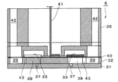
図3は、記録ヘッド6の内部構成を説明する要部断面図である。
本実施形態における記録ヘッド6は、ノズルプレート31、流路基板32、および、圧電素子33等から概略構成され、これらの部材を積層した状態でケース35に取り付けられている。ノズルプレート31は、ドット形成密度に対応したピッチで複数のノズル37を同方向に沿って列状に開設したシリコン単結晶基板からなる部材である。本実施形態では、並設された複数のノズル37から構成されるノズル列(ノズル群の一種)がノズルプレート31に2列並設されている。そして、このノズルプレート31のインクが噴射される側の面が、ノズル面に相当する。
FIG. 3 is a cross-sectional view of a main part for explaining the internal configuration of the
The
上記ノズル37は、ドライエッチングにより内径が異なる複数段の円筒状に形成されている。本実施形態におけるノズル37は、後述する圧力室38側の第1のノズル部37aと、噴射側の第2のノズル部37bとにより2段構造となっている(図9参照)。そして、第1のノズル部37aの内径は、第2のノズル部37bの内径よりも大きく設定されている。より具体的には、第2のノズル部37bの内径が20〔μm〕であるのに対し、第1のノズル部37aの内径は45〔μm〕となっている。また、第2のノズル部37bの軸方向の長さが30〔μm〕、第1のノズル部37aの軸方向の長さは40〔μm〕となっている。なお、ノズルプレート31としては、シリコン単結晶基板に限られず、例えばステンレス鋼等の金属板より構成することもできる。また、ノズル37としては、内径が一定な円筒状のストレート部を噴射側に少なくとも有するものであればよく、ノズル全体の内径が一定のもの(円筒状のノズル)や、第1のノズル部37aに対応する部分の内径が噴射側から圧力室側に向けて拡大するテーパー形状のもの等を採用することもできる。
The
流路基板32は、複数の隔壁で区画された圧力室38が各ノズル37に対応して複数形成されている。この流路基板32における圧力室38の列の外側には、共通液室39の一部を区画する共通液室39が形成されている。この共通液室39は、インク供給口43を介して各圧力室38と個々に連通している。また、共通液室39には、インクカートリッジ17側からのインクがケース35のインク導入路42を通じて導入される。流路基板32のノズルプレート31側とは反対側の上面には、弾性膜40を介して圧電素子33(アクチュエーターの一種)が形成されている。圧電素子33は、金属製の下電極膜と、例えばチタン酸ジルコン酸鉛等からなる圧電体層と、金属からなる上電極膜(何れも図示せず)とを順次積層することで形成されている。この圧電素子33は、所謂撓みモードの圧電素子であり、圧力室38の上部を覆うように形成されている。本実施形態において、2列のノズル列に対応して2列の圧電素子列が、ノズル列方向で見て圧電素子33が互い違いとなる状態でノズル列に直交する方向に並設されている。各圧電素子33は、配線部材41を通じて駆動信号が印加されることにより変形する。これにより、当該圧電素子33に対応する圧力室38内のインクに圧力変動が生じ、このインクの圧力変動を制御することによりノズル37からインクが噴射される。
In the
本発明に係るプリンター1では、例えば、記録ヘッド6が記録媒体に対する記録処理中において定期的に、あるいは、記録ヘッド6のノズル面(ノズルプレート31)をワイピング機構22により払拭した後に、ノズル37からインクが正常に噴射されているか否かの検査(ノズル検査処理)を行い、検査結果に応じてノズル37内の気泡を除去する目的とするフラッシング処理を行う点に特徴を有している。以下、この点について説明する。
In the
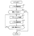
図4は、上記プリンター1の制御の流れを説明するフローチャートである。また、図5は、ノズル異常検出機構14によるノズル37の噴射状態の検査の原理を説明する模式図である。上述したように、記録処理中の一定間隔毎あるいはワイピング処理後に、記録ヘッド6をホームポジションのキャッピング機構20の上方まで移動させてノズル検査処理が行われる(ステップS1)。ノズル異常検出機構14は、ホームポジションのキャッピング機構20に設けられた液体受部としてのキャップ25に対して記録ヘッド6のノズル37からインクを噴射させた際のインクの飛翔速度や重量を検出する。キャッピング機構20におけるキャップ25の内部には、導電性を有するインク吸収体28と共にメッシュ状の電極部材29が配設されている。そして、例えば、電極部材29が正極、記録ヘッド6のノズルプレート31が負極となるように電界が付与される。ここで、電極部材29は、導電性を有するインク吸収材28と接触しているため、インク吸収材28の表面も電極部材29と同電位となる。そして、ノズル異常検出機構14は、ノズル37からインクが噴射されてキャップ25内のインク吸収材28の表面に着弾するまでの電圧変化を検出し、検出信号としてプリンターコントローラー7の制御部9に出力する。
FIG. 4 is a flowchart for explaining the control flow of the
制御部9は、キャリッジ16をホームポジションのキャッピング機構20まで移動させて記録ヘッド6のノズル面をキャップ25と対峙させ、この状態で各ノズル37に対して噴射動作を行わせてノズル異常検出機構14によるノズル検査処理を実行する。ノズル37から噴射されるインクの飛翔方向が本来目標とする方向から著しく曲がっていたり、噴射されたインクの量(重量・体積)が目標とする値から著しく逸脱していたり、或いは、ノズル37からインクが噴射されなかったりする等の噴射異常が生じた場合、ノズル異常検出機構14からの検出信号の値が正常時の値から変化する。このような噴射異常が生じる原因の一つとして、ノズル37内の液体に混入した気泡が挙げられる。制御部9は、検出信号の値が正常時の値から変化した場合に当該ノズル37について噴射異常が生じていると判断する。そして、ノズル検査処理の後、制御部9は検査結果に基づいて噴射に異常のあるノズル37があったか否かを判定する(ステップS2)。噴射異常が生じているノズル37が無い、つまり、全てのノズル37はインクを正常に噴射することができる(No)と判定された場合、ステップS3以降の処理が行われることなく処理が終了する。一方、ステップS2において、噴射異常が生じているノズル37がある(Yes)と判定すると、制御部9は、キャリッジ移動機構4を制御して、キャリッジ16をフラッシングボックス23上まで移動させて記録ヘッド6のノズル面をインク受部27と対峙させ(図1参照)、この状態で、インクを正常に噴射することができなかったノズル37に対してフラッシング処理を実行する(ステップS3)。
The control unit 9 moves the
本実施形態におけるフラッシング処理は、ノズル37からインクを噴射させる動作を行い、主にノズル37の内部(メニスカス近傍)に存在する気泡を排出することを目的とするメンテナンス処理であり、プリンター1の電源が投入されてから記録処理に先立ってノズル37内や圧力室38内の増粘したインクや気泡を排出するために行われるフラッシング処理とは異なるものである。ここで、フラッシング処理における噴射動作は、ノズル37からインクが実際に噴射されるか否かに拘わらず、後述するフラッシングパルスPfにより圧電素子33を駆動して圧力室38内に圧力変動を生じさせる動作を意味する。
The flushing process in the present embodiment is a maintenance process that performs an operation of ejecting ink from the
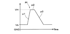
図6は、ステップS3のフラッシング処理で用いられるフラッシング用駆動信号の一例を説明する波形図である。また、図7は、フラッシングパルスPfの構成を説明する波形図である。本実施形態におけるフラッシング用駆動信号COMfは、一定の間隔で発生される合計3つのフラッシングパルスPfを発生する。このフラッシングパルスPfは、ノズル37におけるメニスカスを初期位置(圧電素子33)から圧力室38側に積極的にメニスカスを引き込むことなく噴射側に押し出してインクを噴射させるメンテナンス駆動波形の一種である。より具体的に説明すると、本実施形態におけるフラッシングパルスPfは、収縮要素p1と、収縮維持要素p2と、膨張要素p3と、からなる。収縮要素p1は、基準電位Vbから収縮電位VHまで電位がプラス側に比較的急峻な勾配で変化する波形要素である。ここで、基準電位Vbが圧電素子33に印加されている状態は初期状態(基準状態)であり、この初期状態におけるノズル37内のメニスカスの位置は本発明における初期位置に相当する。この初期位置にあるメニスカスは、ノズル37における噴射側(圧力室38とは反対側)の開口付近(やや圧力室38寄り)に位置する。基準電位Vbから収縮電位VHまでの電位差Vdおよび収縮要素p1の電位変化の勾配は、上記構成の記録ヘッド6で噴射可能な最大量のインクをノズル37から噴射させ得るように設定されている。収縮維持要素p2は、収縮電位VHを所定時間維持する波形要素である。そして、膨張要素p3は、収縮電位VHから基準電位Vbまで電位が十分に緩やかな勾配で変化する波形要素である。なお、メニスカスを圧力室側に積極的に引き込まないとは、基本的には、フラッシングパルスPfにおいて収縮要素p1の前に、圧力室38を膨張させてメニスカスを圧力室側に引き込む波形要素が無いことを意味する。ただし、収縮要素p1の前にこのような他の波形要素があったとしても、収縮要素p1が圧電素子33に印加される時点で気泡が元の状態(圧力室を膨張させる波形要素によって圧力室が膨張される前の状態)に概ね戻っていれば、このような他の波形要素が収縮要素p1の前にあってもよい。
FIG. 6 is a waveform diagram for explaining an example of the flushing drive signal used in the flushing process of step S3. FIG. 7 is a waveform diagram illustrating the configuration of the flushing pulse Pf. The flushing drive signal COMf in the present embodiment generates a total of three flushing pulses Pf generated at regular intervals. The flushing pulse Pf is a kind of maintenance drive waveform that ejects ink by pushing the meniscus in the
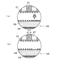
図9は、フラッシング処理においてノズル37からインクが噴射される様子を説明する模式図(ノズル37の断面図)である。図9(a)は、上記の初期状態を示している。この状態において、ノズル37における第2のノズル部37bの内部のインクには気泡Bが滞留している。このノズル37は、気泡Bにより噴射異常が生じている噴射異常ノズルである。上記のように構成されたフラッシングパルスPfがこのノズル37に対応する圧電素子33に印加されると、収縮要素p1により圧電素子33が圧力室38の内側(ノズルプレート31に近接する側)に撓む。これに伴い、圧力室38は基準電位Vbに対応する基準容積から収縮電位VHに対応する収縮容積まで急激に収縮される。これにより、圧力室38内のインクが加圧されて、初期位置にあるメニスカスがノズル中心軸方向に沿って噴射側に急激に押し出され、液柱のように伸びる(図9(b))。この際、メニスカス近傍の気泡Bは、ノズル内のインクに追従して噴射側に押し出される。このとき、気泡Bは、圧力室38内の内圧の上昇に伴って収縮する。
FIG. 9 is a schematic diagram (a cross-sectional view of the nozzle 37) illustrating a state in which ink is ejected from the
圧力室38の収縮状態は、収縮維持要素p2によって一定時間維持される。この間には、噴射側に押し出された液柱の後端部分がメニスカスと分離して、気泡Bを含んだ状態で、フラッシングボックス23のインク受部27に向けて飛翔する(図9(c))。収縮維持要素p2の後、続いて膨張要素p3が印加されることにより、圧電素子33が基準電位Vbに対応する状態まで収縮する。これに伴い、圧力室38は、収縮容積から基準電位Vbに対応する基準容積まで緩やかに膨張して復帰する。これにより、メニスカスが初期位置まで次第に復帰する。このフラッシングパルスPfによりノズル37から噴射されるインクの1滴あたりの重量は、約10〔ng〕である。これに対し、記録媒体に対して画像等を記録する際にノズル37から噴射されるインク1滴あたりの重量は、約7〔ng〕である。フラッシングパルスPfにおいて、膨張要素p3は、収縮要素p1と比較して電位の変化が緩やかであるため、この膨張要素p3により圧電素子33が駆動して圧力室38内に生じる圧力変化も比較的緩やかである。このため、噴射動作後の残留振動も比較的低く抑えることができる。
The contraction state of the
本実施形態においては、1回のフラッシング処理において、1つのノズル37に対応する圧電素子33に対して上記フラッシングパルスPfが一定の間隔で3回印加されて、噴射動作が行われる。気泡Bにより噴射異常が生じているノズル37では、最初の噴射動作ではインクが噴射されない可能性もあるが、フラッシングパルスPfによる噴射動作を3回行うことでより、ノズル37からインクを噴射させて気泡を排出することができる。このときのパルスPfの印加間隔は、前の噴射動作により圧力室38およびノズル37内のインクに生じた残留振動が次の噴射動作が行われるタイミングまでに概ね収束している程度の時間に設定されている。これにより、フラッシング処理におけるメニスカス近傍の気泡Bの排出性が高められる。すなわち、前の噴射動作で生じた残留振動が収まっていない状態で次の噴射動作が行われると、残留振動を励振してしまう場合がある。そして、残留振動が大きくなってしまうと、これに応じてノズル37内の気泡Bの膨張・収縮の度合も大きくなってしまう。そして、気泡Bが膨張すると、浮力によって圧力室側に移動してしまうため、フラッシング処理における気泡排出性が低下する虞がある。例えば、ノズル37の軸方向においてメニスカスから圧力室側に35〔μm〕の範囲に気泡Bが位置していれば、フラッシングパルスPfによるフラッシング処理によって当該気泡Bを排出することができる。しかしながら、ノズル37の中心軸方向においてメニスカスから35〔μm〕の範囲を超えて気泡Bが遠ざかってしまうと、フラッシング処理によっても気泡Bを排出することが困難となってしまう。
In the present embodiment, in one flushing process, the flushing pulse Pf is applied three times at regular intervals to the
ここで、ノズル内の気泡Bに働く浮力は、気泡Bの直径をr、インクの密度をρ、重力加速度をgとして、アルキメデスの定理より、以下の式(1)で表される。
F=4πr3ρg/3 …(1)
次に、気泡Bに働く抵抗力は、インクの粘度をη、気泡Bの速度(ノズル内壁による流路抵抗を無視した場合の速度(無限液中速度))をUとして、以下の式(2)で表される。
F=6πηrV …(2)
式(1)および式(2)より、インク内の気泡Bの浮上速度Uは、以下の式(3)で表される。
U=4.5r2ρg/η …(3)
すなわち、上記式(3)より、気泡Bが大きいほど、その浮上速度が上昇することがわかる。
なお、ノズル37内における気泡Bの浮上速度uは、ノズル37の内径をd、λ=r/dとして、以下のCliftら提案の式(4)またはWallis提案の式(5)で表すことができる。
u/U=(1−λ2)3/2 for λ<0.6 …(4)
u/U=(1.13exp(−λ) for λ<0.6 …(5)
例えば、d=20〔μm〕、r=10〔μm〕とすると、λ=0.5となり、第2のノズル部37bにおける気泡Bの浮上速度uは、
式(4)より u=0.650×U=9.42〔μm/s〕
式(5)より u=0.685×U=9.94〔μm/s〕
となる。
したがって、フラッシング処理においては、気泡Bをできるだけ膨張させないことが肝要となる。このため、圧力室38の内圧の変化、特に急激な減圧を避け、なおかつ、気泡Bの大きさを変化させる原因となる残留振動を可及的に抑えることが望ましい。
Here, the buoyancy acting on the bubble B in the nozzle is expressed by the following formula (1) from Archimedes' theorem, where r is the diameter of the bubble B, ρ is the density of the ink, and g is the acceleration of gravity.
F = 4πr 3 ρg / 3 (1)
Next, the resistance force acting on the bubble B is expressed by the following equation (2), where η is the viscosity of the ink, and U is the velocity of the bubble B (the velocity when the flow path resistance due to the nozzle inner wall is ignored (infinite liquid velocity)). ).
F = 6πηrV (2)
From the equations (1) and (2), the flying speed U of the bubbles B in the ink is expressed by the following equation (3).
U = 4.5r 2 ρg / η (3)
That is, from the above formula (3), it can be seen that the larger the bubble B, the higher the rising speed.
The rising speed u of the bubble B in the
u / U = (1-λ 2 ) 3/2 for λ <0.6 (4)
u / U = (1.13exp (−λ) for λ <0.6 (5)
For example, if d = 20 [μm] and r = 10 [μm], then λ = 0.5, and the rising speed u of the bubbles B in the
From equation (4) u = 0.650 × U = 9.42 [μm / s]
From equation (5) u = 0.585 × U = 9.94 [μm / s]
It becomes.
Therefore, in the flushing process, it is important not to expand the bubbles B as much as possible. For this reason, it is desirable to avoid a change in the internal pressure of the
本実施形態においては、ノズル37におけるメニスカスを初期位置(圧電素子33)から圧力室38側には実質的に変化させずにインクを噴射させるフラッシングパルスPfをフラッシング処理における噴射動作用の駆動波形として採用することで、フラッシング処理において圧力室内の急激な減圧を避けて気泡Bが膨張することによる浮上を抑制している。また、前のフラッシングパルスPfの終端(膨張要素p3の終端)から次のフラッシングパルスPfの始端(収縮要素p1の始端)までの時間Δtが、圧力室38内のインクに生じる振動(圧力波)のヘルムホルツ振動周期(固有振動周期)Tc以上となるように設定されている。これにより、前の噴射動作により生じた残留振動が概ね収束している状態で次の噴射動作が行われるので、気泡Bが不必要に膨張・収縮することが低減される。このため、気泡Bが浮力により圧力室38側に移動することが抑制され、気泡排出性を高めることができる。また、1回のフラッシング処理において上記間隔で噴射動作を3回行うことで、ノズル37内の気泡を概ね排出することができる。例えば、ノズル37の内壁に気泡が付着していて、1回目の噴射動作によりノズル37からインクを噴射させなかったとしても、1回目の噴射動作でインクが噴射側に押し出されるので、このインクの動きにより気泡がノズル内壁から離れて動きやすくなり、2回目、3回目の噴射動作により、気泡Bをインクと共にノズル37から排出させることができる。なお、ノズル37内のインクの気泡をより効果的に排出するには、本実施形態のようにフラッシングパルスPfにより3回噴射動作を行うことが望ましいが、ノズル37内の気泡Bを排出することができれば、例えば、3回の噴射動作のうち少なくとも最初の噴射動作をフラッシングパルスPfで行い、残りを他の駆動パルス、具体的には後述する一般的なフラッシングパルスPf′あるいは通常の記録動作で使用される駆動パルス等を用いて行う構成を採用することもできる。また、フラッシング動作においては、3回の噴射動作には限られず、4回以上とすることも可能である。この場合、4回目以降の駆動パルスは、フラッシングパルスPfでも他の駆動パルスでも良い。
In the present embodiment, the flushing pulse Pf that ejects ink without substantially changing the meniscus in the
ここで、上記Tcは、ノズル37、圧力室38、インク供給口43、及び圧電素子33等の各構成部材の形状、寸法、及び剛性などにより、記録ヘッド毎に固有に定まる。この固有の振動周期Tcは、例えば、次式(1)で表すことができる。
Tc=2π√[〔(Mn×Ms)/(Mn+Ms)〕×Cc] …(6)
但し、式(4)において、Mnはノズル37におけるイナータンス、Msはインク供給口43におけるイナータンス、Ccは圧力室38のコンプライアンス(単位圧力あたりの容積変化、柔らかさの度合いを示す。)である。また、上記式(6)において、イナータンスMとは、流路における液体の移動し易さを示し、換言すると、単位断面積あたりの液体の質量である。そして、流体の密度をρ、流路の流体の流下方向と直交する面の断面積をS、流路の長さをLとしたとき、イナータンスMは次式(7)で近似して表すことができる。
M=(ρ×L)/S …(7)
なお、上記Tcは、上記式(6)で規定されるものに限られず、記録ヘッド6の圧力室38が有している振動周期であればよい。
Here, the Tc is uniquely determined for each recording head depending on the shape, size, rigidity, and the like of each component such as the
Tc = 2π√ [[(Mn × Ms) / (Mn + Ms)] × Cc] (6)
In Equation (4), Mn is inertance at the
M = (ρ × L) / S (7)
The Tc is not limited to that defined by the above formula (6), and may be any vibration cycle that the
このようにして、フラッシング処理が実行された後、続いてステップS4においてノズル異常検出機構14によるノズル検査処理が再度実行される。そして、ノズル検査処理の後、制御部9は検査結果に基づいてノズル37から正常にインクが噴射されたか(仕様上目標とする量および飛翔速度でインクが噴射されているか)否かを判定する(ステップS5)。この際、噴射異常が生じているノズル37が無い、つまり、全てのノズル37はインクを正常に噴射することができる(Yes)と判定された場合、処理が終了する。一方、ステップS5において、インクが正常に噴射されていない(No)と判定すると、ステップS3に戻り、以降の処理が実行される。なお、インクが正常に噴射されていないと判定された場合にステップS3で再度上記のフラッシング処理を実行することに替えて、例えば、キャッピング機構20によりノズル面をキャッピングした状態でノズル37からインクを吸引する所謂クリーニング処理等、プリンターにおいて一般的に行われるメンテナンス処理を行うようにすることもできる。
After the flushing process is executed in this manner, the nozzle inspection process by the nozzle
ここで、比較のため、従来の一般的なフラッシング処理に用いられるフラッシングパルスPf′について説明する。
図8は、フラッシングパルスPf′の構成を説明する波形図である。また、図10は、フラッシングパルスPf′によりノズル37からインクが噴射される様子を説明する模式図である。このフラッシングパルスPf′は、予備膨張要素p11と、膨張維持要素p12と、収縮要素p13と、収縮維持要素p14と、膨張要素p15と、からなる。すなわち、このフラッシングパルスPf′は、ノズル37からインクを噴射させる前に、まず、予備膨張要素p11により圧力室38を膨張させて、メニスカスを圧力室側に大きく引き込む(図10(a))。これにより、メニスカス近傍の気泡Bも圧力室側に移動する。また、このときの圧力室38内の内圧の減少に伴って気泡Bは膨張するので、上述したように浮上してメニスカスから圧力室38側に離れてしまう。このため、その後収縮要素p13により圧力室38が収縮されてメニスカスが噴射側に急激に押し出されても、気泡Bはメニスカスに追従できない(図10(b))。その結果、ノズル37からインクが噴射されても気泡Bは排出されずノズル37に残ったままとなってしまう(図10(c))。
Here, for comparison, a flushing pulse Pf ′ used in a conventional general flushing process will be described.
FIG. 8 is a waveform diagram illustrating the configuration of the flushing pulse Pf ′. FIG. 10 is a schematic diagram for explaining how ink is ejected from the
これに対し、本発明に係るフラッシングパルスPfは、メニスカスを初期位置から圧力室側に実質的に変位させることなく、つまり、インクの撹拌は抑えつつ、初期位置からインクを押し出してノズル37から噴射させるので、メニスカス近傍の気泡Bが不必要に膨張することが抑制され、これにより当該気泡Bが圧力室側に浮上することを抑えつつ、より少ない噴射量で効率よく気泡Bを排出することができる。
In contrast, the flushing pulse Pf according to the present invention ejects ink from the
また、1回の噴射動作で噴射されるインクの量が比較的少ない駆動波形、例えば、プリンター1において最も小さい液滴を噴射させる小ドット用の駆動パルスに関し、噴射動作においては、メニスカスを引き込んだり押し込んだりを繰り返して微小な液滴を噴射するように構成されているため、インクの振動が複雑化しやすく、また、ノズル内の気泡もそれに応じて膨張・収縮を繰り返すため、気泡がメニスカスから離れてしまい、ノズル内の気泡排出性に劣る問題がある。これに対し、本実施形態においては、プリンター1において噴射可能な最大の液量を噴射させる駆動波形であるフラッシングパルスPfを採用しているため、フラッシング処理において一度により多くのインクをノズル37から噴射させることができるとともに、上記のような微小なインク滴を噴射させる駆動波形と比較して噴射動作時の圧力室38内の圧力変化が穏やかであるため、圧力室38内に不必要な振動を生じさせにくく、ノズル内のインクと共に気泡をより効率よく排出させることができる。
Further, regarding a drive waveform in which the amount of ink ejected in one ejection operation is relatively small, for example, a drive pulse for small dots that ejects the smallest droplet in the
このように、本発明に係るプリンター1においては、インクの無駄な消費を抑えつつノズル37内部の気泡をインクと共に排出することが可能となる。すなわち、ノズル検査処理においてインクを正常に噴射することができなかったノズル37に対して少なくとも最初にフラッシングパルスPfを用いてフラッシング処理が行われることで、無駄なフラッシング処理が行われることなく、しかも、1回のフラッシング処理においては噴射動作を1乃至3回行うだけでノズル内の気泡が排出されるので、従来のフラッシング処理や吸引によるクリーニング処理等のメンテナンス処理と比較してインクの消費を大幅に抑えることが可能となる。
Thus, in the
なお、上記実施形態では、アクチュエーターとして、所謂撓み振動型の圧電素子33を例示したが、これには限られず、例えば、所謂縦振動型の圧電素子を採用することも可能である。この場合、上記実施形態で例示したフラッシングパルスPfに関し、電位の変化方向、つまり上下が反転した波形となる。
また、アクチュエーターとしては圧電素子には限らず、静電気力を利用して圧力室の容積を変動させる静電アクチュエーター等の各種アクチュエーターを用いる場合にも本発明を適用することができる。
In the above-described embodiment, the so-called flexural vibration type
The actuator is not limited to a piezoelectric element, and the present invention can also be applied to various actuators such as an electrostatic actuator that changes the volume of a pressure chamber using electrostatic force.
さらに、ノズル異常検出機構14に関し、上記実施形態においてはインク滴を帯電させてこれを検出することで、ノズル37の噴射異常を検出するように構成を例示したが、これには限られない。例えば、記録媒体に検査パターン等を印刷し、このパターンを光学的なセンサーで検査して、噴射異常の有無を検出するようにしてもよい。また、インク滴噴射後の残留振動によって圧電素子に生じる逆起電力信号に基づいて、噴射異常の有無を検出するようにしてもよい。その他、レーザーを照射する照射部とこのレーザーを検出する検出部とを備え、飛翔するインク滴がレーザーを遮蔽するか否かを検出したり、噴射されたインク滴の重量を検出したりすることで、噴射異常の有無を検出することもできる。
Furthermore, regarding the nozzle
そして、本発明は、ノズル内の気泡を排出させるフラッシング処理を行う液体噴射装置であれば、上記のプリンターに限らず、プロッター、ファクシミリ装置、コピー機等、各種のインクジェット式記録装置、あるいは、着弾対象の一種である布帛(被捺染材)に対して液体噴射ヘッドからインクを着弾させて捺染を行う捺染装置、または、記録装置以外の液体噴射装置、例えば、ディスプレイ製造装置、電極製造装置、チップ製造装置等にも適用することができる。 The present invention is not limited to the above printer as long as it is a liquid ejecting apparatus that performs a flushing process for discharging bubbles in the nozzles, and various ink jet recording apparatuses such as plotters, facsimile machines, and copiers, or landing A printing apparatus that performs printing by landing ink from a liquid ejecting head on a cloth (material to be printed) that is a target, or a liquid ejecting apparatus other than a recording apparatus, such as a display manufacturing apparatus, an electrode manufacturing apparatus, and a chip The present invention can also be applied to a manufacturing apparatus or the like.
1…プリンター,6…記録ヘッド,9…制御部,11…駆動信号生成部,14…ノズル異常検出機構,20…キャッピング機構,22…ワイピング機構,25…キャップ,23…フラッシングボックス,27…インク受け部,31…ノズルプレート,33…圧電素子,37…ノズル,38…圧力室
DESCRIPTION OF
Claims (5)
前記ノズルについて液体の噴射の異常を検出する検出機構と、
を備え、駆動波形によりアクチュエーターを駆動してメンテナンス処理を行うことが可能な液体噴射装置であって、
前記検出機構により異常が検出されたノズルに対応する前記アクチュエーターに前記駆動波形を複数回印加して噴射動作を行わせるメンテナンス処理において、少なくとも最初にアクチュエーターに印加される駆動波形は、前記ノズルにおけるメニスカスを初期位置から前記圧力室側に積極的に引き込むことなく前記噴射側に押し出して当該ノズルから液体を噴射させるメンテナンス駆動波形であることを特徴とする液体噴射装置。 A liquid ejecting head having a pressure chamber communicating with the nozzle, and an actuator for causing a pressure fluctuation in the liquid in the pressure chamber, and capable of ejecting the liquid from the nozzle by the operation of the actuator;
A detection mechanism for detecting an abnormality in liquid ejection for the nozzle;
A liquid ejecting apparatus capable of performing maintenance processing by driving an actuator with a drive waveform,
In the maintenance process in which the drive waveform is applied to the actuator corresponding to the nozzle in which the abnormality is detected by the detection mechanism to perform the ejection operation, the drive waveform applied to the actuator at least first is a meniscus in the nozzle. A liquid ejecting apparatus having a maintenance driving waveform in which liquid is ejected from the nozzle by positively pushing out the nozzle from the initial position to the pressure chamber without being actively pulled into the pressure chamber.
液体の噴射の異常が検出されたノズルに対応する前記アクチュエーターに前記駆動波形を複数回印加して噴射動作を行わせるメンテナンス処理において、前記ノズルにおけるメニスカスを初期位置から前記圧力室側に積極的に引き込むことなく前記噴射側に押し出して当該ノズルから液体を噴射させるメンテナンス駆動波形を前記アクチュエーターに少なくとも最初に印加することを特徴とする液体噴射ヘッドの制御方法。 A control method of a liquid ejecting head having a pressure chamber communicating with a nozzle and an actuator that causes a pressure fluctuation in the liquid in the pressure chamber, and capable of ejecting the liquid from the nozzle by driving the actuator with a driving waveform. And
In a maintenance process in which the drive waveform is applied to the actuator corresponding to the nozzle in which the abnormality of liquid ejection is detected to perform the ejection operation, the meniscus in the nozzle is actively moved from the initial position to the pressure chamber side. A method of controlling a liquid ejecting head, wherein a maintenance drive waveform for ejecting liquid from the nozzles without being pulled in is ejected at least first to the actuator.
液体の噴射の異常が検出されたノズルに対応する前記アクチュエーターに前記駆動波形を複数回印加して噴射動作を行わせるメンテナンス処理において、前記ノズルにおけるメニスカスを初期位置から前記圧力室側に積極的に引き込むことなく前記噴射側に押し出して当該ノズルから液体を噴射させるメンテナンス駆動波形を前記アクチュエーターに少なくとも最初に印加する液体噴射装置の制御方法。
A pressure chamber that communicates with the nozzle, and an actuator that causes pressure fluctuations in the liquid in the pressure chamber, the liquid ejecting head capable of ejecting the liquid from the nozzle by the operation of the actuator, and the ejection of the liquid from the nozzle A detection mechanism for detecting an abnormality, and a control method for a liquid ejecting apparatus capable of performing maintenance processing by driving an actuator with a drive waveform,
In a maintenance process in which the drive waveform is applied to the actuator corresponding to the nozzle in which the abnormality of liquid ejection is detected to perform the ejection operation, the meniscus in the nozzle is actively moved from the initial position to the pressure chamber side. A control method for a liquid ejecting apparatus, wherein a maintenance drive waveform for ejecting liquid from the nozzle without being pulled in is ejected at least first to the actuator.
Priority Applications (3)
| Application Number | Priority Date | Filing Date | Title |
|---|---|---|---|
| JP2014109721A JP2015223762A (en) | 2014-05-28 | 2014-05-28 | Liquid injection device, control method of liquid injection head and control method of liquid injection device |
| US14/720,657 US9475280B2 (en) | 2014-05-28 | 2015-05-22 | Liquid ejecting apparatus, control method of liquid ejecting head, and control method of liquid ejecting apparatus |
| US15/277,908 US20170028715A1 (en) | 2014-05-28 | 2016-09-27 | Liquid ejecting apparatus, control method of liquid ejecting head, and control method of liquid ejecting apparatus |
Applications Claiming Priority (1)
| Application Number | Priority Date | Filing Date | Title |
|---|---|---|---|
| JP2014109721A JP2015223762A (en) | 2014-05-28 | 2014-05-28 | Liquid injection device, control method of liquid injection head and control method of liquid injection device |
Publications (2)
| Publication Number | Publication Date |
|---|---|
| JP2015223762A true JP2015223762A (en) | 2015-12-14 |
| JP2015223762A5 JP2015223762A5 (en) | 2017-10-05 |
Family
ID=54700764
Family Applications (1)
| Application Number | Title | Priority Date | Filing Date |
|---|---|---|---|
| JP2014109721A Pending JP2015223762A (en) | 2014-05-28 | 2014-05-28 | Liquid injection device, control method of liquid injection head and control method of liquid injection device |
Country Status (2)
| Country | Link |
|---|---|
| US (2) | US9475280B2 (en) |
| JP (1) | JP2015223762A (en) |
Cited By (1)
| Publication number | Priority date | Publication date | Assignee | Title |
|---|---|---|---|---|
| CN109130500A (en) * | 2017-06-16 | 2019-01-04 | 精工爱普生株式会社 | Fluid ejection head, liquid ejection apparatus and its drive control circuit and driving method |
Families Citing this family (6)
| Publication number | Priority date | Publication date | Assignee | Title |
|---|---|---|---|---|
| TW201737771A (en) * | 2016-03-13 | 2017-10-16 | 肯提克有限公司 | A printer and a method for printing ink on a substrate |
| US11446925B2 (en) | 2017-04-06 | 2022-09-20 | Hewlett-Packard Development Company, L.P. | Fluid supply control |
| WO2018186862A1 (en) * | 2017-04-06 | 2018-10-11 | Hewlett-Packard Development Company, L.P. | Nozzle characteristics |
| EP3403829A1 (en) * | 2017-05-18 | 2018-11-21 | OCE Holding B.V. | Method for opening a clogged nozzle |
| JP7415402B2 (en) * | 2019-09-30 | 2024-01-17 | セイコーエプソン株式会社 | Liquid injection device control method and liquid injection device |
| CN111016465B (en) * | 2019-12-24 | 2021-09-07 | 珠海艾派克微电子有限公司 | Chip and imaging box |
Citations (6)
| Publication number | Priority date | Publication date | Assignee | Title |
|---|---|---|---|---|
| JP2000118004A (en) * | 1998-10-19 | 2000-04-25 | Seiko Epson Corp | Ink-jet type recording apparatus |
| US20010028371A1 (en) * | 1996-07-24 | 2001-10-11 | Wen-Li Su | Acoustic and ultrasonic monitoring of inkjet droplets |
| JP2007130853A (en) * | 2005-11-09 | 2007-05-31 | Fujifilm Corp | Liquid ejector and method for extracting cause of abnormal ejection |
| JP2008036977A (en) * | 2006-08-07 | 2008-02-21 | Brother Ind Ltd | Inkjet recorder |
| JP2009073076A (en) * | 2007-09-21 | 2009-04-09 | Seiko Epson Corp | Flushing method for fluid jetting apparatus |
| JP2013035138A (en) * | 2011-08-03 | 2013-02-21 | Ricoh Co Ltd | Image forming apparatus |
Family Cites Families (5)
| Publication number | Priority date | Publication date | Assignee | Title |
|---|---|---|---|---|
| JP3374862B2 (en) * | 1992-06-12 | 2003-02-10 | セイコーエプソン株式会社 | Ink jet recording device |
| JP5055701B2 (en) * | 2005-02-24 | 2012-10-24 | ブラザー工業株式会社 | Inkjet head flushing method |
| DE102005011194A1 (en) * | 2005-03-09 | 2006-09-14 | Neoperl Gmbh | Sanitary outlet fitting |
| JP5272363B2 (en) * | 2007-09-21 | 2013-08-28 | セイコーエプソン株式会社 | Fluid ejection device |
| JP2011104774A (en) * | 2009-11-12 | 2011-06-02 | Seiko Epson Corp | Liquid ejecting apparatus and control method thereof |
-
2014
- 2014-05-28 JP JP2014109721A patent/JP2015223762A/en active Pending
-
2015
- 2015-05-22 US US14/720,657 patent/US9475280B2/en active Active
-
2016
- 2016-09-27 US US15/277,908 patent/US20170028715A1/en not_active Abandoned
Patent Citations (6)
| Publication number | Priority date | Publication date | Assignee | Title |
|---|---|---|---|---|
| US20010028371A1 (en) * | 1996-07-24 | 2001-10-11 | Wen-Li Su | Acoustic and ultrasonic monitoring of inkjet droplets |
| JP2000118004A (en) * | 1998-10-19 | 2000-04-25 | Seiko Epson Corp | Ink-jet type recording apparatus |
| JP2007130853A (en) * | 2005-11-09 | 2007-05-31 | Fujifilm Corp | Liquid ejector and method for extracting cause of abnormal ejection |
| JP2008036977A (en) * | 2006-08-07 | 2008-02-21 | Brother Ind Ltd | Inkjet recorder |
| JP2009073076A (en) * | 2007-09-21 | 2009-04-09 | Seiko Epson Corp | Flushing method for fluid jetting apparatus |
| JP2013035138A (en) * | 2011-08-03 | 2013-02-21 | Ricoh Co Ltd | Image forming apparatus |
Cited By (1)
| Publication number | Priority date | Publication date | Assignee | Title |
|---|---|---|---|---|
| CN109130500A (en) * | 2017-06-16 | 2019-01-04 | 精工爱普生株式会社 | Fluid ejection head, liquid ejection apparatus and its drive control circuit and driving method |
Also Published As
| Publication number | Publication date |
|---|---|
| US20150343763A1 (en) | 2015-12-03 |
| US9475280B2 (en) | 2016-10-25 |
| US20170028715A1 (en) | 2017-02-02 |
Similar Documents
| Publication | Publication Date | Title |
|---|---|---|
| EP3061608B1 (en) | Liquid ejecting apparatus | |
| JP2015223762A (en) | Liquid injection device, control method of liquid injection head and control method of liquid injection device | |
| JP2008168565A (en) | Fluid jetting device | |
| US20150360471A1 (en) | Liquid ejecting apparatus, control method of liquid ejecting head, and control method of liquid ejecting apparatus | |
| US10059096B2 (en) | Liquid discharging apparatus, control method of liquid discharging apparatus, device driver, and printing system | |
| JP4241838B2 (en) | Flushing method for liquid ejecting apparatus and liquid ejecting apparatus | |
| JP4379477B2 (en) | Flushing method for liquid ejecting apparatus | |
| JP2010131979A (en) | Liquid injection device, and method of controlling the same | |
| JP6451109B2 (en) | Liquid ejection device and method for controlling liquid ejection device | |
| JP6307904B2 (en) | Liquid ejecting apparatus and method for controlling liquid ejecting apparatus | |
| JP2011104916A (en) | Liquid jetting apparatus | |
| JP2011207078A (en) | Liquid ejecting apparatus and method for controlling the same | |
| JP2011235594A (en) | Pulse setting method of liquid ejector | |
| JP6512036B2 (en) | Liquid discharge device | |
| US20120256986A1 (en) | Liquid ejecting apparatus and method of controlling liquid ejecting apparatus | |
| US9283751B2 (en) | Liquid ejecting apparatus and method of controlling liquid ejecting apparatus | |
| JP2015229343A (en) | Liquid injection device, control method of liquid injection head, control method of liquid injection device | |
| JP2015223763A (en) | Liquid injection device, control method of liquid injection head and control method of liquid injection device | |
| JP6048098B2 (en) | Method for driving liquid discharge head and image forming apparatus | |
| JP2011110716A (en) | Liquid ejecting apparatus, and, control method thereof | |
| JP5041161B2 (en) | Liquid ejecting apparatus and liquid ejecting head cleaning method | |
| JP2011000819A (en) | Fluid jetting apparatus and operating method thereof | |
| JP2015009519A (en) | Liquid jet apparatus | |
| JP5619361B2 (en) | Fluid ejecting apparatus and fluid ejecting apparatus cleaning method | |
| JP2012240257A (en) | Liquid ejection device and control method for the same |
Legal Events
| Date | Code | Title | Description |
|---|---|---|---|
| A621 | Written request for application examination |
Free format text: JAPANESE INTERMEDIATE CODE: A621 Effective date: 20170309 |
|
| A521 | Request for written amendment filed |
Free format text: JAPANESE INTERMEDIATE CODE: A523 Effective date: 20170825 |
|
| A977 | Report on retrieval |
Free format text: JAPANESE INTERMEDIATE CODE: A971007 Effective date: 20171122 |
|
| A131 | Notification of reasons for refusal |
Free format text: JAPANESE INTERMEDIATE CODE: A131 Effective date: 20171128 |
|
| A131 | Notification of reasons for refusal |
Free format text: JAPANESE INTERMEDIATE CODE: A131 Effective date: 20180327 |
|
| A02 | Decision of refusal |
Free format text: JAPANESE INTERMEDIATE CODE: A02 Effective date: 20180814 |