JP2015536501A - System and method for providing infrared gesture instructions on a display - Google Patents
System and method for providing infrared gesture instructions on a display Download PDFInfo
- Publication number
- JP2015536501A JP2015536501A JP2015539756A JP2015539756A JP2015536501A JP 2015536501 A JP2015536501 A JP 2015536501A JP 2015539756 A JP2015539756 A JP 2015539756A JP 2015539756 A JP2015539756 A JP 2015539756A JP 2015536501 A JP2015536501 A JP 2015536501A
- Authority
- JP
- Japan
- Prior art keywords
- user
- touch
- gesture
- display
- touch screen
- Prior art date
- Legal status (The legal status is an assumption and is not a legal conclusion. Google has not performed a legal analysis and makes no representation as to the accuracy of the status listed.)
- Pending
Links
- 238000000034 method Methods 0.000 title claims abstract description 53
- 238000012545 processing Methods 0.000 claims abstract description 39
- 230000000875 corresponding effect Effects 0.000 claims description 24
- 230000004044 response Effects 0.000 claims description 10
- 230000002452 interceptive effect Effects 0.000 abstract description 10
- 238000004140 cleaning Methods 0.000 abstract description 4
- 239000006260 foam Substances 0.000 description 28
- 230000006870 function Effects 0.000 description 25
- 230000008569 process Effects 0.000 description 25
- 238000010586 diagram Methods 0.000 description 9
- 239000006261 foam material Substances 0.000 description 9
- 239000011521 glass Substances 0.000 description 9
- 230000007704 transition Effects 0.000 description 9
- 230000008878 coupling Effects 0.000 description 8
- 238000010168 coupling process Methods 0.000 description 8
- 238000005859 coupling reaction Methods 0.000 description 8
- 238000001514 detection method Methods 0.000 description 8
- 230000009471 action Effects 0.000 description 6
- 239000000463 material Substances 0.000 description 6
- 239000002783 friction material Substances 0.000 description 4
- 238000004891 communication Methods 0.000 description 3
- 238000013461 design Methods 0.000 description 3
- 238000005516 engineering process Methods 0.000 description 3
- 230000005057 finger movement Effects 0.000 description 3
- 239000000853 adhesive Substances 0.000 description 2
- 230000001070 adhesive effect Effects 0.000 description 2
- 230000008901 benefit Effects 0.000 description 2
- 210000000845 cartilage Anatomy 0.000 description 2
- 238000006243 chemical reaction Methods 0.000 description 2
- 238000000605 extraction Methods 0.000 description 2
- 238000005286 illumination Methods 0.000 description 2
- 230000003993 interaction Effects 0.000 description 2
- 238000012986 modification Methods 0.000 description 2
- 230000004048 modification Effects 0.000 description 2
- 230000007935 neutral effect Effects 0.000 description 2
- IRLPACMLTUPBCL-KQYNXXCUSA-N 5'-adenylyl sulfate Chemical compound C1=NC=2C(N)=NC=NC=2N1[C@@H]1O[C@H](COP(O)(=O)OS(O)(=O)=O)[C@@H](O)[C@H]1O IRLPACMLTUPBCL-KQYNXXCUSA-N 0.000 description 1
- 229920006353 Acrylite® Polymers 0.000 description 1
- JOYRKODLDBILNP-UHFFFAOYSA-N Ethyl urethane Chemical compound CCOC(N)=O JOYRKODLDBILNP-UHFFFAOYSA-N 0.000 description 1
- 229910052779 Neodymium Inorganic materials 0.000 description 1
- 229920005372 Plexiglas® Polymers 0.000 description 1
- 238000013459 approach Methods 0.000 description 1
- 239000011230 binding agent Substances 0.000 description 1
- 239000007767 bonding agent Substances 0.000 description 1
- 230000001413 cellular effect Effects 0.000 description 1
- 230000006835 compression Effects 0.000 description 1
- 238000007906 compression Methods 0.000 description 1
- 230000001276 controlling effect Effects 0.000 description 1
- 238000010411 cooking Methods 0.000 description 1
- 238000012937 correction Methods 0.000 description 1
- PCHJSUWPFVWCPO-UHFFFAOYSA-N gold Chemical compound [Au] PCHJSUWPFVWCPO-UHFFFAOYSA-N 0.000 description 1
- 239000010931 gold Substances 0.000 description 1
- 229910052737 gold Inorganic materials 0.000 description 1
- 239000004519 grease Substances 0.000 description 1
- 238000003384 imaging method Methods 0.000 description 1
- 238000003331 infrared imaging Methods 0.000 description 1
- 230000007774 longterm Effects 0.000 description 1
- 239000006249 magnetic particle Substances 0.000 description 1
- 238000005259 measurement Methods 0.000 description 1
- 238000010295 mobile communication Methods 0.000 description 1
- 238000012544 monitoring process Methods 0.000 description 1
- QEFYFXOXNSNQGX-UHFFFAOYSA-N neodymium atom Chemical compound [Nd] QEFYFXOXNSNQGX-UHFFFAOYSA-N 0.000 description 1
- 230000003287 optical effect Effects 0.000 description 1
- INFDPOAKFNIJBF-UHFFFAOYSA-N paraquat Chemical compound C1=C[N+](C)=CC=C1C1=CC=[N+](C)C=C1 INFDPOAKFNIJBF-UHFFFAOYSA-N 0.000 description 1
- 239000002245 particle Substances 0.000 description 1
- 229920003023 plastic Polymers 0.000 description 1
- 239000004033 plastic Substances 0.000 description 1
- 229920001084 poly(chloroprene) Polymers 0.000 description 1
- 230000005855 radiation Effects 0.000 description 1
- 238000006748 scratching Methods 0.000 description 1
- 230000002393 scratching effect Effects 0.000 description 1
- 230000035945 sensitivity Effects 0.000 description 1
- 230000003068 static effect Effects 0.000 description 1
- 238000002834 transmittance Methods 0.000 description 1
- 210000001364 upper extremity Anatomy 0.000 description 1
Images


Classifications
-
- G—PHYSICS
- G06—COMPUTING; CALCULATING OR COUNTING
- G06F—ELECTRIC DIGITAL DATA PROCESSING
- G06F3/00—Input arrangements for transferring data to be processed into a form capable of being handled by the computer; Output arrangements for transferring data from processing unit to output unit, e.g. interface arrangements
- G06F3/01—Input arrangements or combined input and output arrangements for interaction between user and computer
- G06F3/03—Arrangements for converting the position or the displacement of a member into a coded form
- G06F3/041—Digitisers, e.g. for touch screens or touch pads, characterised by the transducing means
- G06F3/0416—Control or interface arrangements specially adapted for digitisers
- G06F3/04166—Details of scanning methods, e.g. sampling time, grouping of sub areas or time sharing with display driving
-
- G—PHYSICS
- G06—COMPUTING; CALCULATING OR COUNTING
- G06F—ELECTRIC DIGITAL DATA PROCESSING
- G06F1/00—Details not covered by groups G06F3/00 - G06F13/00 and G06F21/00
- G06F1/16—Constructional details or arrangements
- G06F1/1601—Constructional details related to the housing of computer displays, e.g. of CRT monitors, of flat displays
- G06F1/1607—Arrangements to support accessories mechanically attached to the display housing
-
- G—PHYSICS
- G06—COMPUTING; CALCULATING OR COUNTING
- G06F—ELECTRIC DIGITAL DATA PROCESSING
- G06F3/00—Input arrangements for transferring data to be processed into a form capable of being handled by the computer; Output arrangements for transferring data from processing unit to output unit, e.g. interface arrangements
- G06F3/01—Input arrangements or combined input and output arrangements for interaction between user and computer
- G06F3/03—Arrangements for converting the position or the displacement of a member into a coded form
- G06F3/041—Digitisers, e.g. for touch screens or touch pads, characterised by the transducing means
- G06F3/042—Digitisers, e.g. for touch screens or touch pads, characterised by the transducing means by opto-electronic means
-
- G—PHYSICS
- G06—COMPUTING; CALCULATING OR COUNTING
- G06F—ELECTRIC DIGITAL DATA PROCESSING
- G06F3/00—Input arrangements for transferring data to be processed into a form capable of being handled by the computer; Output arrangements for transferring data from processing unit to output unit, e.g. interface arrangements
- G06F3/01—Input arrangements or combined input and output arrangements for interaction between user and computer
- G06F3/048—Interaction techniques based on graphical user interfaces [GUI]
- G06F3/0487—Interaction techniques based on graphical user interfaces [GUI] using specific features provided by the input device, e.g. functions controlled by the rotation of a mouse with dual sensing arrangements, or of the nature of the input device, e.g. tap gestures based on pressure sensed by a digitiser
- G06F3/0488—Interaction techniques based on graphical user interfaces [GUI] using specific features provided by the input device, e.g. functions controlled by the rotation of a mouse with dual sensing arrangements, or of the nature of the input device, e.g. tap gestures based on pressure sensed by a digitiser using a touch-screen or digitiser, e.g. input of commands through traced gestures
- G06F3/04883—Interaction techniques based on graphical user interfaces [GUI] using specific features provided by the input device, e.g. functions controlled by the rotation of a mouse with dual sensing arrangements, or of the nature of the input device, e.g. tap gestures based on pressure sensed by a digitiser using a touch-screen or digitiser, e.g. input of commands through traced gestures for inputting data by handwriting, e.g. gesture or text
-
- G—PHYSICS
- G06—COMPUTING; CALCULATING OR COUNTING
- G06F—ELECTRIC DIGITAL DATA PROCESSING
- G06F2203/00—Indexing scheme relating to G06F3/00 - G06F3/048
- G06F2203/041—Indexing scheme relating to G06F3/041 - G06F3/045
- G06F2203/04105—Pressure sensors for measuring the pressure or force exerted on the touch surface without providing the touch position
-
- G—PHYSICS
- G06—COMPUTING; CALCULATING OR COUNTING
- G06F—ELECTRIC DIGITAL DATA PROCESSING
- G06F2203/00—Indexing scheme relating to G06F3/00 - G06F3/048
- G06F2203/041—Indexing scheme relating to G06F3/041 - G06F3/045
- G06F2203/04106—Multi-sensing digitiser, i.e. digitiser using at least two different sensing technologies simultaneously or alternatively, e.g. for detecting pen and finger, for saving power or for improving position detection
Landscapes
- Engineering & Computer Science (AREA)
- General Engineering & Computer Science (AREA)
- Theoretical Computer Science (AREA)
- Human Computer Interaction (AREA)
- Physics & Mathematics (AREA)
- General Physics & Mathematics (AREA)
- Computer Hardware Design (AREA)
- User Interface Of Digital Computer (AREA)
Abstract
赤外線のジェスチャ捕捉及び認証を提供するタッチセンサ式の表示デバイスに関するシステム、方法及び装置が説明される。取り外し可能なフロントパネルを備える表示デバイスは、対話型のタッチセンサ式で赤外線のジェスチャ捕捉及び処理を可能とする。赤外線の光源及び赤外線カメラは、デバイスの取り外し可能なフロントパネル上でなされる複雑でマルチタッチのジェスチャの画像を捕捉するよう構成され得る。取り外し可能なフロントパネルは、クリーニング及び使いやすさのために表示デバイスから取り外し得る。Systems, methods, and apparatus for touch-sensitive display devices that provide infrared gesture capture and authentication are described. A display device with a detachable front panel enables interactive gesture-sensitive touch capture and processing of infrared gestures. The infrared light source and infrared camera can be configured to capture images of complex and multi-touch gestures made on the removable front panel of the device. The removable front panel can be removed from the display device for cleaning and ease of use.
Description
[0001]ここに示されたデバイス、システムおよび方法は、一般的に電子デバイスに関するユーザインターフェース、具体的には特に、電子デバイス用のタッチセンサ式のディスプレイを使用する赤外線ジェスチャ認証に関する。 [0001] The devices, systems and methods presented herein relate generally to user interfaces for electronic devices, and more particularly to infrared gesture authentication using a touch-sensitive display for electronic devices.
[0002]タッチセンサ式のディスプレイは、電子デバイス上で有名なインターフェースで、ユーザが容易にコマンドとデータを入力することを可能にする。タッチディスプレイはモバイルデバイス、電子表示、タブレット、ラップトップおよびデスクトップコンピュータにおいて見つけ得る。タッチディスプレイは、一般的に、指タッチ、スタイラスタッチ、指の動きあるいはタッチスクリーン面上のスタイラス動きに応答し、動作するように設計されている。 [0002] Touch-sensitive displays are well-known interfaces on electronic devices that allow users to easily enter commands and data. Touch displays can be found in mobile devices, electronic displays, tablets, laptops and desktop computers. Touch displays are generally designed to operate in response to finger touch, stylus touch, finger movement or stylus movement on a touch screen surface.
[0003]タッチディスプレイ上で特定箇所に触れることは、タッチディスプレイ上のその場所で見つけられ、或いは示された機能、特徴あるいは、仮想ボタンを活性化し得る。典型的な特徴は、例えば、他の機能と一緒になって、電話を掛けること、データを入力すること、ブラウザウィンドウを開け閉めすること、を含み得る。 [0003] Touching a particular location on the touch display may be found at that location on the touch display or may activate the indicated function, feature, or virtual button. Typical features may include, for example, making a call, entering data, opening and closing a browser window, along with other functions.
[0004]いくつかの環境では、タッチスクリーンは、マルチタッチ入力のような、複雑なユーザジェスチャを正確に解決することは出来得ない。この不正確は、ディスプレイ上のタッチセンサ内の感度の欠落の結果であり得、あるいはユーザからのマルチタッチ入力の複雑さに起因し得る。 [0004] In some environments, touch screens cannot accurately resolve complex user gestures, such as multi-touch input. This inaccuracy may be the result of a lack of sensitivity within the touch sensor on the display or may be due to the complexity of multi-touch input from the user.
[0005]さらに、携帯電話のような、ある電子デバイスは、タッチスクリーン上のユーザによる動きの量を制限する、比較的小さなディスプレイを有し得る。ある例において、表示画面に触れることにより複雑なコマンドを入力することはユーザにとって難しいかもしれない。 [0005] Furthermore, certain electronic devices, such as cell phones, may have a relatively small display that limits the amount of movement by the user on the touch screen. In some examples, it may be difficult for the user to enter complex commands by touching the display screen.
[0006]本開示のシステム、方法、およびデバイスはそれぞれ、いくつかの革新的な観点を有し、これらのうちの何れも、ここに開示される所望の属性を単独で担うものではない。 [0006] Each of the disclosed systems, methods, and devices has several innovative aspects, none of which is solely responsible for the desired attributes disclosed herein.
[0007]一実施形態は、ディスプレイの背面に搭載された赤外線の光源とカメラを有する対話型のジェスチャ認証に関するシステムである。いくつかの具体化では、システムは、取り外し可能なフロントパネルを更に有し得、それは、赤外線カメラと圧力検出器を使用して、複雑なタッチ相互作用を提供をもし得る。取り外し可能なフロントパネルのいくつかの実施形態は、枠のないガラスを備え得る。表示デバイスが汚れまたは油脂に晒される環境では、枠を有していないことは、汚れか油脂が、枠とガラスとの間の接触線に集まることから防ぐ利点を備えており、それは完全にガラスから汚れを取り除くことは難しくなり得る。フロントパネルの取り外し可能な特性は、ディスプレイ自身が、汚れや油脂によって触られない上に(while the display itself remains untouched by dirt or grease)、フロントパネルは洗浄するために取り外され得るため、ユーザが散らかった環境の中で快適にディスプレイを使用することを可能にする。さらに、ディスプレイが引っ掻かれ、あるいは破損され得るような環境では、ディスプレイを保護するための取り外し可能なパネルを有することは、破損に対して晒された、容易に代替可能なコンポーネントを有することによりディスプレイの寿命を伸ばす。 [0007] One embodiment is a system for interactive gesture authentication having an infrared light source and camera mounted on the back of a display. In some implementations, the system can further include a removable front panel, which can also provide complex touch interaction using an infrared camera and pressure detector. Some embodiments of the removable front panel may comprise unframed glass. In environments where the display device is exposed to dirt or oil, the absence of a frame has the advantage of preventing dirt or oil from collecting on the contact lines between the frame and the glass, which is completely glassy. Removing dirt from can be difficult. The detachable nature of the front panel makes the display itself untouched by dirt and grease while the front panel can be removed for cleaning, which can be confusing to the user. This makes it possible to use the display comfortably in a dry environment. Further, in environments where the display can be scratched or damaged, having a removable panel to protect the display is due to having easily replaceable components that are exposed to damage. Extend the life of the display.
[0008]別の実施形態は、ユーザのタッチを検知可能なタッチスクリーンと、タッチスクリーンの前に置かれたユーザ指に光を当てるように構成された1つまたは複数の赤外線の光源と、タッチスクリーンの背面に配置され、タッチスクリーンを通じてユーザの指の赤外線画像を捕捉するよう構成された赤外線カメラと、ユーザの指の位置を追跡しタッチスクリーン上のユーザのタッチを判断するように構成されたジェスチャ処理モジュールと、を備え、ここにおいて、ジェスチャ処理モジュールは、判断されたタッチ及び位置の追跡からユーザジェスチャを判断する。 [0008] Another embodiment includes a touch screen capable of sensing a user's touch, one or more infrared light sources configured to illuminate a user finger placed in front of the touch screen, and a touch An infrared camera located on the back of the screen and configured to capture an infrared image of the user's finger through the touch screen, and configured to track the position of the user's finger and determine the user's touch on the touch screen A gesture processing module, wherein the gesture processing module determines a user gesture from the determined touch and position tracking.
[0009]また別の実施形態は、前面及び背面を有し、ユーザのタッチを検知可能なタッチスクリーンと、タッチスクリーンの前に置かれたユーザの指に光を当てるように構成された1つまたは複数の赤外線の光源と、タッチスクリーンの背面に配置され、タッチスクリーンを通じてユーザの指の赤外線画像を捕捉するよう構成された赤外線カメラと、を含むタッチセンサ式の表示デバイス上でのユーザジェスチャをキャプチャするためのシステムである。システムは、更にユーザが前記タッチスクリーンをタッチした時、ジェスチャ認証モジュールを活性化し、タッチセンサ式の表示デバイスのタッチスクリーン上で作られたユーザジェスチャの1つまたは複数の画像を捕捉し、ユーザがタッチスクリーンを離した時、ジェスチャ認証モジュールの動作を停止させ、表示上の対応する動作を実行するためにユーザジェスチャの画像を解析する、ように構成された、制御モジュールを含む。 [0009] Yet another embodiment includes a touch screen having a front surface and a back surface that is sensitive to a user's touch and one configured to shine light on a user's finger placed in front of the touch screen. Or a user gesture on a touch-sensitive display device comprising a plurality of infrared light sources and an infrared camera disposed on the back of the touch screen and configured to capture an infrared image of the user's finger through the touch screen. It is a system for capturing. The system further activates a gesture authentication module when the user touches the touch screen and captures one or more images of the user gesture made on the touch screen of the touch-sensitive display device. A control module configured to stop the operation of the gesture authentication module and analyze the image of the user gesture to perform a corresponding operation on the display when the touch screen is released is included.
[0010]他の一実施形態は、全面及び背面を有し、ユーザのタッチを検知可能なタッチスクリーンと、ユーザがタッチスクリーンをタッチした時、赤外線の光源を供給する手段と、タッチセンサ式の表示デバイスのタッチスクリーン上でなされたユーザジェスチャの1つまたは複数の画像を捕捉する手段と、ユーザがタッチスクリーンを離した時、ユーザジェスチャの画像の捕捉を中断し、赤外線の光源の使用を停止する手段と、表示上の対応する動作を実行するためのユーザジェスチャの画像を解析する手段、を含むタッチセンサ式の表示デバイスである。 [0010] Another embodiment includes a touch screen having an entire surface and a back surface, capable of detecting a user's touch, means for supplying an infrared light source when the user touches the touch screen, and a touch sensor type Means for capturing one or more images of user gestures made on the touch screen of the display device, and when the user releases the touch screen, interrupts capturing of the user gesture images and stops using the infrared light source And a means for analyzing an image of a user gesture for performing a corresponding operation on the display.
[0011]更に別の実施形態は、タッチセンサ式のデバイス上のユーザタッチから圧力を検知することと、ユーザタッチが検出されると、赤外線の光源を有効にすることと、タッチセンサ式の表示デバイス上でなされたユーザジェスチャの1つまたは複数の画像を捕捉することと、タッチセンサ式の電子デバイスの表示上の対応する動作を実行するためのユーザジェスチャの画像を解析することのステップを含む、タッチセンサ式の電子デバイス内にデータを入力するための方法である。 [0011] Yet another embodiment includes sensing pressure from a user touch on a touch-sensitive device, enabling an infrared light source when a user touch is detected, and touch-sensitive display Capturing one or more images of a user gesture made on the device and analyzing the image of the user gesture to perform a corresponding operation on the display of the touch-sensitive electronic device. A method for inputting data into a touch-sensitive electronic device.
[0012]他の一実施形態は、プロセッサによって実行されると、タッチセンサ式の電子デバイス内にデータを入力する方法を実行する命令を具備する非一時的なコンピュータ可読記憶媒体である。方法は、タッチセンサ式のデバイス上のユーザタッチから圧力を検知することと、ユーザタッチが検出されると、赤外線の光源を有効にすることと、タッチセンサ式の表示デバイス上でなされたユーザジェスチャの1つまたは複数の画像を捕捉することと、タッチセンサ式の電子デバイスの表示上の、対応する動作を実行するためのユーザジェスチャの前記画像を解析することとを含む。 [0012] Another embodiment is a non-transitory computer-readable storage medium comprising instructions that, when executed by a processor, perform a method for entering data into a touch-sensitive electronic device. The method includes sensing pressure from a user touch on a touch-sensitive device, enabling an infrared light source when a user touch is detected, and user gestures made on the touch-sensitive display device. Capturing one or more images and analyzing the image of a user gesture for performing a corresponding action on a display of a touch-sensitive electronic device.
[0013]開示される観点は、開示されたこれら観点を限定するためでなく、例示するために提供される、別表及び添付図面と併せて以下に説明され、ここにおいて同様の表記は同様の要素を示す。
[0024]実施形態は、電子システムに情報を入力するための画像システムの使用に関する。一実施形態において、履行は、ユーザの指の動きを捕捉するための赤外線画像システムを利用し、表示スクリーン上のタッチベースの入力を提供するための動作を使用する、システム、デバイス、方法、或いはデバイスを含む。これは、赤外線マルチタッチ対話型のジェスチャ認識を有するタッチセンサ式の表示デバイスのために提供する。 [0024] Embodiments relate to the use of an imaging system to enter information into an electronic system. In one embodiment, fulfillment utilizes an infrared imaging system to capture the movement of the user's fingers and uses an action to provide touch-based input on the display screen, system, device, method, or Includes devices. This provides for a touch-sensitive display device with infrared multi-touch interactive gesture recognition.
[0025]例えば、一実施形態では、デバイスは、赤外光に対して透明であるが、付属の電子システムからの情報を表示する表示パネルを有し得る。そのようなディスプレイは、LCDまたはLED表示パネルを含み得る。赤外線カメラと光源は、下で述べられるように、ユーザから反対の表示パネルの後ろに位置され、表示パネルの全面の動きをとらえるために焦点を合わせ得る。ユーザが表示パネルの前で、一本の指、あるいは指の集合を動かすと、赤外線カメラは、ユーザの指のサインを捕らえ得、どのジェスチャが現在行なわれているか確定するためにそのサインを分析し得る。電子システム内で稼働するソフトウェアは、行われる適切なジェスチャを確定するためのユーザの指の動作を分析するために使用され得る。 [0025] For example, in one embodiment, the device is transparent to infrared light, but may have a display panel that displays information from an attached electronic system. Such a display may include an LCD or LED display panel. The infrared camera and light source are positioned behind the opposite display panel from the user, as described below, and can be focused to capture movement of the entire display panel. When the user moves one finger or a set of fingers in front of the display panel, the infrared camera can capture the user's finger signature and analyze the signature to determine which gesture is currently taking place Can do. Software running within the electronic system can be used to analyze the movement of the user's finger to determine the appropriate gesture to be made.
[0026]一実施形態では、ディスプレイは、付属の電子システムからのユーザへ情報を表示するために使用される表示パネルを保持するフレームを含み得る。表示パネルは、適切な場所にパネルを保持する他の手段またはマグネットを用いたフレームをしっかり固定され得る、取り外し可能な、透明なパネルによってカバーされ得る。赤外線の光源と赤外線カメラは、表示パネル及び透明なパネルの後ろに配置され、ユーザの複雑なマルチタッチジェスチャの認識および解釈を提供するために使用され得る。多くの圧力センサは、ディスプレイに関する透明なパネルの動作が、ユーザのタッチの位置を確定するために分析される圧力センサ信号を生成するように、フレームに付属され得る。このタッチ信号は、いつシステムが赤外線カメラを使用して、タッチジェスチャの捕捉を始めるべきか確定するために使用され得る。したがって、使用において、システムは、フレーム上の圧力センサからの透明なパネル上の圧力を検知するために走査する。圧力を検知した時、システムは、どこで指圧が生じたのかを特定するためスクリーン上の圧力イベントの座標位置を計算する。その後、システムは、検知された位置から指の動きをモニタするための赤外線画像センサと光を初期化する。この動きをモニタすることによって、システムは、タッチセンサを集積していないが、その代りに指の位置を検知するための圧力センサを使用する透明なパネルを横切る場合でさえ、複雑な指の動きを追跡することができる。いくつかの実施形態では、取り外し可能で透明なパネルは、枠のないガラス製パネルである。 [0026] In one embodiment, the display may include a frame that holds a display panel that is used to display information to a user from an attached electronic system. The display panel can be covered by a removable, transparent panel that can be secured to the frame using other means or magnets to hold the panel in place. An infrared light source and an infrared camera are placed behind the display panel and transparent panel and can be used to provide recognition and interpretation of the user's complex multi-touch gestures. Many pressure sensors can be attached to the frame such that the movement of the transparent panel relative to the display generates a pressure sensor signal that is analyzed to determine the position of the user's touch. This touch signal can be used to determine when the system should begin capturing touch gestures using an infrared camera. Thus, in use, the system scans to sense pressure on the transparent panel from the pressure sensor on the frame. When pressure is detected, the system calculates the coordinate position of the pressure event on the screen to identify where the finger pressure occurred. The system then initializes the infrared image sensor and light to monitor finger movement from the detected position. By monitoring this movement, the system does not integrate touch sensors, but instead complex finger movements even across transparent panels that use pressure sensors to detect finger position. Can be tracked. In some embodiments, the removable transparent panel is an unframed glass panel.
[0027]発明の実施形態は、多数の他の用途の広い或いは特別目的のコンピューティングシステムの環境か設定で使用可能である。本発明での使用に適しうる周知のコンピューティングシステム、環境、および/または構成の例は、限定されるものではないが、パーソナルコンピュータ、サーバコンピュータ、ハンドヘルド(hand-held)型またはラップトップ型のデバイス、マルチプロセッサシステム、マイクロプロセッサベースのシステム、プログラム可能な家庭用電化製品、ネットワークPC、ミニコンピュータ、任意の上記のシステムまたはデバイスを含む分散型コンピュータ環境、およびその類似したものを含む。 [0027] Embodiments of the invention may be used in many other versatile or special purpose computing system environments or settings. Examples of well-known computing systems, environments, and / or configurations that may be suitable for use with the present invention include, but are not limited to, personal computers, server computers, hand-held or laptop types Includes devices, multiprocessor systems, microprocessor-based systems, programmable consumer electronics, network PCs, minicomputers, distributed computing environments including any of the above systems or devices, and the like.
[0028]ここで使用されるように、命令は、システム中で情報を処理するための、コンピュータで履行するステップを指す。命令はソフトウェア、ファームウェア、またはハードウェアで履行され得、システムの要素により引き受けられる(undertaken)プログラムされたステップの任意のタイプを含むことができる。 [0028] As used herein, instructions refer to computer-implemented steps for processing information in a system. The instructions may be implemented in software, firmware, or hardware and may include any type of programmed steps that are undertaken by system elements.
[0029]以下の説明では、特定の詳細は、例についての完全な理解を提供するために与えられる。しかしながら、当業者であれば、これら例がこれらの特定の詳細なしで実施されうることを理解するであろう。例えば、これら例を不必要な詳細で不明瞭にしないように、電気コンポーネント/デバイスはブロック図で示されうる。他の事例では、このようなコンポーネント、他の構造および技術が、これら例をさらに説明するために詳細に示されうる。 [0029] In the following description, specific details are given to provide a thorough understanding of the examples. However, one skilled in the art will understand that these examples may be practiced without these specific details. For example, electrical components / devices may be shown in block diagrams in order not to obscure the examples in unnecessary detail. In other instances, such components, other structures and techniques may be shown in detail to further explain these examples.
[0030]また、これら例は、フローチャート、フロー図、有限状態図、構造図、またはブロック図として図示される、プロセスとして説明されうることに留意されたい。フローチャートは、動作を順次プロセスとして説明しうるが、これら動作の多くは並列または同時並行に実行されることができ、また、プロセスは繰り返されることができる。加えて、動作の順序は並べ換えることができる。処理は、その動作が完了した時に終了する。プロセスは、方法、関数、プロシージャ、サブルーチン、サブプログラム等に対応しうる。プロセスがソフトウェア関数に対応する時、その終了は、この関数が呼び出し関数または主関数に戻ることに対応する。 [0030] It should also be noted that these examples may be described as processes, illustrated as flowcharts, flow diagrams, finite state diagrams, structure diagrams, or block diagrams. Although a flowchart may describe the operations as a sequential process, many of these operations can be performed in parallel or concurrently, and the process can be repeated. In addition, the order of operations can be rearranged. The process ends when the operation is complete. A process may correspond to a method, a function, a procedure, a subroutine, a subprogram, etc. When a process corresponds to a software function, its termination corresponds to this function returning to the calling function or the main function.
[0031]当業者であれば、情報および信号は、様々な異なる技術および技法のうちの任意のものを用いて表されうることを理解するであろう。例えば、上記説明の全体にわたって参照されうるデータ、命令、コマンド、情報、信号、ビット、シンボル、およびチップは、電圧、電流、電磁波、磁場または磁性粒子、光場または光粒子、あるいはこれらの任意の組み合わせによって表されうる。 [0031] Those skilled in the art will appreciate that information and signals may be represented using any of a variety of different technologies and techniques. For example, data, instructions, commands, information, signals, bits, symbols, and chips that may be referenced throughout the above description are voltages, currents, electromagnetic waves, magnetic fields or magnetic particles, light fields or light particles, or any of these Can be represented by a combination.
表示デバイスの概観
[0032]発明の実施形態は、取り外し可能なフロントパネルを有する、タッチセンサ式のデバイスに関係があり、そこで、ディスプレイ上に配置された圧力センサ及びディスプレイの背面に配置された赤外線(IR)カメラは、対話型のタッチセンシングおよびジェスチャ認識を提供する。一典型的なデバイスは、2013年1月4日に出願され、その全体中のこの参照によりここに組み込まれた、“取り外し可能なフロントパネルを有する対話型のディスプレイ(INTERACTIVE DISPLAY WITH REMOVABLE FRONT PANEL)”と題された、米国仮特許出願番号61/749、184に記載されている。赤外線ジェスチャの認識機能は、記述された実施形態中で示されるようなタッチセンサ式の表示デバイス上で提供され得る。他の実施形態では、赤外線ジェスチャの認識は、ラップトップ、デスクトップあるいはモバイルデバイスに制限されていないが、そのような他の電子デバイス上で提供され得る。
Overview of display devices
[0032] Embodiments of the invention relate to a touch-sensitive device having a removable front panel, where a pressure sensor disposed on the display and an infrared (IR) camera disposed on the back of the display Provides interactive touch sensing and gesture recognition. One exemplary device is “INTERACTIVE DISPLAY WITH REMOVABLE FRONT PANEL,” filed on Jan. 4, 2013 and incorporated herein by reference in its entirety. In U.S. Provisional Patent Application No. 61 / 749,184. Infrared gesture recognition can be provided on a touch-sensitive display device as shown in the described embodiments. In other embodiments, recognition of infrared gestures is not limited to laptops, desktops or mobile devices, but may be provided on such other electronic devices.
[0033]図1は、レッグ20、25によって支えられるフレーム構造(図示せぬ)上に搭載された枠が無く、取り外し可能な透明のフロントパネルを有するタッチセンサ式の表示システム5の一実施形態を示す。タッチセンサ式の表示システム5は、ユーザに情報を表示するよう構成される。示されるように、ディスプレイ10は、有線か、あるいは無線で、ディスプレイ10上にユーザへの内容を表示するように構成された、ラップトップ、デスクトップ、又は他の処理デバイスのようなコンピュータ11に接続され得る。いくつかの実施形態では、コンピュータ11は、ディスプレイ10に集積され得る。システム5は、有線又は無線で、タッチセンサ式のディスプレイ10からのユーザ入力をアップロードし、またディスプレイ10にコンテンツをダウンロードするために、コンピュータ11を介してインターネットのような、広域エリアネットワーク13にも接続され得る。ディスプレイ10は、ここで更に詳細に説明されるように、赤外線の光源および赤外線カメラ(図示せず)を含み得、マルチタッチジェスチャの認証を用いて動作するように構成され得る。ユーザは、既知のユーザコマンドジェスチャと関連され、カメラによってキャプチャされ得る、マルチタッチジェスチャを用いてシステム5に入力を提供し得る。加えて、ユーザは、例えば、バーチャルキーボードを使用して、ディスプレイシステム5への入力を提供し得る。入力は、例えば、テキスト、数字、記号、および/または制御コマンドを含み得る。
[0033] FIG. 1 illustrates one embodiment of a touch-
[0034]図1に示されるように、ディスプレイ10は、スタンドアロンの表示デバイスである。しかしながら、ネットワークとの通信に関して適した他のデバイスが使用され得る。コンピュータ11に関連する表示デバイス10は、インターネット13上の他のデバイスから情報を受信するために、及び情報を送信するために使用され得る。通信された情報は、例えば、ボイス、データおよび/またはマルチメディアサービスを含み得る。表示デバイス10およびコンピュータ11も、例えば、セルラーネットワークを含む、インターネット13に加えてネットワーク上で通信するためにも使用され得る。
[0034] As shown in FIG. 1, the
[0035]コンピュータ11および表示デバイス10は、様々な規格を用いて通信し得る。例えば、あるユーザデバイスは、IEEE16.11(a)、(b)、または(g)を含むIEEE16.11規格、あるいはIEEE802.11a、b、gまたはnを含むIEEE802.11規格に従って通信し得る。いくつかの実施形態では、ユーザデバイスは、BLUETOOTH(登録商標)規格に従って、RF信号を送信および受信するためのアンテナを含み得る。ユーザデバイスが携帯電話であるときのような、あるユーザデバイスでは、ユーザデバイスは、符号分割多元接続(CDMA)、周波数分割多元接続(FDMA)、時分割多元接続(TDMA)、グローバル移動体通信システム(GSM(登録商標))、GSM/汎用パケット無線システム(GPRS)、エンハンストデータGSM環境(EDGE:Enhanced Data GSM Environment)、TETRA(Terrestrial Trunked Radio)、広帯域CDMA(W−CDMA(登録商標))、EV−DO(Evolution Data Optimized)、1xEV−DO、EV−DO Rev A、EV−DO Rev B、高速パケットアクセス(HSPA)、高速ダウンリンクパケットアクセス(HSDPA)、高速アップリンクパケットアクセス(HSUPA)、発展型高速パケットアクセス(HSPA+)、ロングタームエボリューション(LTE)、AMPS、または3Gあるいは4Gの技術を利用するシステムのような、無線ネットワーク内で通信するために使用される他の既知信号を受信するように設計されるアンテナを使用して、通信することができる。
[0035] The computer 11 and the
[0036]図2は、取り外し可能なフロントパネル15を有するタッチセンサ式の表示デバイス10の一実施形態の透視図を示す。表示デバイス10は、ガラス(図示せず)のバックパネルに結合された2本のレッグ20および25から構築されるフレーム16によってサポートされる。レッグ20および25は、機械的な留め具、あるいは接着剤のような結合剤によって、グラスのバックパネルと結合され得る。アクティブな表示パネル17は、コンピュータ11、スマートフォンあるいはタブレットのような結合された電子システムからユーザへの情報を表示する画素の実際のディスプレイを提供する。アクティブな表示パネル17は、ガラスのバックパネル表面上に位置する。アクティブな表示パネル17は、透明なLCDディスプレイのような、あらゆる種類のフラットパネル技術になり得る。いくつかの構成では、アクティブな表示パネル17は枠を取りはずした、22インチの三星LTI220MT02ディスプレイであり得る。
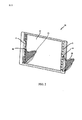
FIG. 2 illustrates a perspective view of one embodiment of a touch-
[0037]透明なフロントパネル15は、それが完全にアクティブな表示パネル17をカバーするように、フレーム16に結合され得る。フロントパネル15は、透明で高い透過率、ほとんど色のなしのガラスで作られ得、好ましくは枠の無い1つの充分に平らな平面の表面を備える。例えば、1つの構成では、フロントパネル15は、長さ約600mm、高さ約340mm、および厚さ約3.3mmを持つ、ユーロホワイト、オプティホワイトあるいはディアマンテとしても知られるスターファイヤーガラスで作られ得る。フロントパネル15は、フロントパネル15とフレームのレッグ20および25との間の磁石の結合によって表示パネル17に取り外し可能に固定され得る。この磁石の結合は、マグネット40および44の厚さの1/2にほぼ等しい深さを有している、浅い溝内のフロントパネル15の内側(underside)に接合した1組のマグネット40および44を含み得る。磁石40および44は、各々レッグ20および25中の中心点に配置されたマッチング磁石ホルダ(図示せず)に搭載するよう更に構成される。浅い溝内でのマグネット40および44の配置は、マグネット40、44を、レッグ20、25において配置された対応するマグネットと一直線にすることを促し、およびさらにフロントパネル15にマグネットを固定している結合剤からある負荷を除去することを促す。表示デバイス10へのフロントパネル15の磁石の結合も、磁石および磁気的に魅力的な材料の組み合わせを通じて達成され得る。この磁石の結合は、アクティブな表示パネル17を使用後に洗うべきアクティブな表示パネル17の前に、フロントパネル15を付属の位置から容易に取り外されることを可能にする。
[0037] A transparent
[0038]図2に示されるように、赤外線の光ユニット8は、デバイス10のレッグ20および25の上に配置され得る。赤外線の光ユニット8は、ディスプレイ10の前面に向かって、すなわちユーザの方へ光を向ける。いくつかの構成では、赤外線の光ユニット8は、デバイス10の両脚のいずれの前面に付属された広角のある光源である。1つの構成では、赤外線の光ユニット8は、約850nmの波長の光を放射する赤外線LED光ユニットであり得る。赤外線の光源は、干渉無しで、透明なアクティブな表示パネル17およびフロントパネル15を直接通り抜け得、したがって、他の構成では、赤外線の光ユニット8は、電子筐体内で、透明なディスプレイを通じてユーザに赤外線の光源を向けるためのディスプレイ10の背面に置かれ得る。
[0038] As shown in FIG. 2, the infrared
[0039]ユーザの手あるいは指からの赤外線の光源の反射は、ディスプレイ10の背後に位置する赤外線カメラ(図示せず)によって捕捉され得る。ユーザジェスチャのこれらの画像は、意図したユーザコマンドのジェスチャを判別するためのジェスチャ処理機能を使用して分析され得る。これらの特徴は、下記に非常に詳しく説明される。
[0039] The reflection of the infrared light source from the user's hand or finger may be captured by an infrared camera (not shown) located behind the
[0040]図3の平面図に示されるように、フロントパネル15は直接、隣接するアクティブな表示パネル17に搭載される。フロントパネル15は、それがフレーム16の側面及び上部からはみ出るように、アクティブ表示パネル17及びバックパネル30よりも大きな幅及び高さを有し得る。いくつかの構成では、料理の中で(in cooking)使用されるもののような共通の測定等価物を示すラベルは、ユーザに有益情報を提供するために、フロントパネル15の横にくっきりと描かれ得る。フロントパネル15の横に配置されることによって、それらはアクティブな表示パネル17をオーバーラップさせ得なく、ディスプレイに示された情報のユーザの視界を遮られ得ない。フロントパネル15は、クリーニングのため容易にフロントパネル15の取り外し及び掴むことを手助けするために基本的なパネルよりも大きくなり得る。いくつかの構成では、表示デバイス10は、フロントパネル15の前面と、バックパネル30の背面のと、間はおよそ1インチの厚さである。他の構成では、表示デバイスは、1インチの4/5又は約20mmの厚さを有している。まださらなる構成では、表示デバイスは、約1インチの1/2の厚さを有し得る。
[0040] As shown in the plan view of FIG. 3, the
[0041]レッグ20および25は、バックパネル30に集積され得、あるいはそれらは、バックパネル30に接合され得る。いくつかの構成では、レッグ20および25は、表示デバイス10に関して安定性と支援を提供するために、プレキシグラスのアクリル、あるいは他の硬質なプラスチックで作られ得る。レッグ20および25は、約1インチの幅であり得、あるいは、それらは、デバイス10の重さを安全に支えるのに十分な他の幅であり得る。いくつかの実施形態では、レッグ20および25は、アクティブな表示パネル17のためにバックライトを供給するための、LEDの光ストリップ18のような、1つまたは複数の光源を含み得る。他の実施形態では、LEDの光ストリップ18は、フレーム16の横側に固定され得る。LEDの光ストリップ18は、アクティブな表示パネル17を照らすために、透明なバックパネル30を通り抜けて光をトンネルさせ又は直接向ける。1つの構成では、LEDの光ストリップ18は、約750nmの波長で減衰する光を放射し得、750nm以上で、この光信号においてほとんどエネルギーの無いことを意味する。LEDの光ストリップ18は、約5000Kあるいは約6500Kの色温度で光を放射し得る。他の色温度は、他の構成の中で使用され得る。
[0041]
[0042]透明なバックパネル30は、透明なアクティブ表示パネル17に向かって前方のレッグ20および25上に配置されたLEDの光ストリップ18からの光を曲げ、あるいは向け得る。いくつかの構成では、バックパネル30は、バージョンOF11LのACRYLITE(R)Endlighten Tで作ら得、それは、透明に見え、またディスプレイ10のための照明を提供するため、バックパネル30の表面の至る所に光を均一に向け直す。
[0042] The
[0043]フレーム16の下に配置されるのは、電子筐体45であり、これは、アクティブ表示パネル17、バックライトLEDストリップ18、赤外線の光ユニット8、赤外線カメラ35、あるいはディスプレイ10内で使用される他の電子コンポーネントを制御するためのプロセッサのような、ディスプレイを稼働させるために必要とされるあらゆる電子機器を収容するために使用され得る。LEDストリップ18が、ディスプレイを照らすためにターンオンする時、光は、ディスプレイの横から、フロントパネルにむかって前方にトンネルする。迷光も、IRカメラ35に向かって後ろへ向かい得る。しかしながら、いくつかの実施形態中において、IRカメラ35は、この波長で光を捕らえないため、この光の波長は、画像を捕捉するためのIRカメラの能力に邪魔をしないだろう。1つの構成では、IRカメラ35は、約850nm及びそれ以上の波長を有する光を捕捉するように設計され得る。
[0043] Located below the
[0044]図3は、さらに、フロントパネル15上でなされたユーザジェスチャの画像を捕捉するように構成された赤外線カメラ35の配置を示す。赤外線カメラ35は、フレーム16の下に配置された電子筐体45内に設置され得る。ディスプレイ10の後ろにIRカメラを置くことは、ディスプレイ10の透明度に起因してゼロ個のカメラ(zero camera)が見えない場所をもたらす。いくつかの構成では、ディスプレイ10は、アクティブな表示パネル17がアクティブでも非アクティブの時でも、赤外線カメラ35に反射された赤外線の光に対して透明である。赤外線の光ユニット8は、ディスプレイ10のフロントパネル15上のユーザジェスチャを捕捉するための赤外線カメラの能力を妨げない。更に、バックライトLEDのストリップ18は、さらにユーザジェスチャの画像を捕捉するための赤外線カメラ35の能力をも妨げない。1つの構成では、IRカメラは、交換式の赤外線レンズを有するCM26F272型カメラであり得る。いくつかの構成では、マルチプル(multiple)のカメラは、フロントパネルのあらゆる位置でなされたジェスチャを捕捉するための広角を提供するために使用され得る。
[0044] FIG. 3 further illustrates an arrangement of an
[0045]赤外線の光ユニットの配置は、赤外線カメラの配置に依存し得る。赤外線カメラの配置は、他の検討事項に共通して(among other considerations)、赤外線カメラの仕様、表示デバイスの全体寸法、コストおよび美的感覚に依存し得る。いくつかの実施形態では、赤外線の光が赤外線カメラに直接向けられないように、赤外線の光源は配置される。 [0045] The placement of the infrared light unit may depend on the placement of the infrared camera. The placement of the infrared camera may depend on the other specifications, infrared camera specifications, overall dimensions of the display device, cost and aesthetics. In some embodiments, the infrared light source is arranged so that the infrared light is not directed directly at the infrared camera.
[0046]いくつかの実施形態では、赤外線の光ユニットは、上述したようにデバイスのレッグ20および25の上に配置され得る。これは、デバイスにクリーンな外観という利点を提供するが、要求されるより多くのIR光ユニットに起因してより大きな複雑さをもたらし得、なぜなら、この構成は、デバイスのフロントパネル全体を照らすために各レッグの上にマルチプルのIRの光ユニットを必要とし得るためである。
[0046] In some embodiments, the infrared light unit may be placed on the
[0047]他の具体化では、IR光ユニットは、単一のモジュール中の赤外線カメラの近くのディスプレイの背後に配置され得る。この構成では、赤外線の光ユニットおよび赤外線カメラの両者は、ユーザに向かって前に向いており、また、赤外線の光は、赤外線カメラに直接向けられていないであろう。 [0047] In other embodiments, the IR light unit may be placed behind the display near the infrared camera in a single module. In this configuration, both the infrared light unit and the infrared camera are facing forward towards the user, and the infrared light will not be directed directly at the infrared camera.
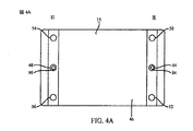
[0048]図4Aは、取り外し可能なフロントパネル15、つまり、フロントパネル15が付けられる時に、アクティブな表示パネル17に面するフロントパネル15の側面の内面46を図式的に示す。図中における“左”及び“右”の表示は、フロントパネル15の方向を指し、またフロントパネル15を有する完全に組み立てられたデバイス10を持つユーザによって見えるような表示デバイス10を指す。示されるように、フロントパネル15は、2セットのマグネットペアの磁石の結合によって表示デバイス10を取り外し可能に固定され得る。他の実施形態では、2セット以上のマグネットのペアは、表示デバイス10に対してフロントパネル15を固定するために使用され得る。
[0048] FIG. 4A schematically shows a removable
[0049]図4Aの中で示されるように、2つのマグネット40および44がフロントパネル15の内側に接着される。マグネット40および44は、好ましくはフロントパネル15の内側に接着されるが、他の接着手段によってフロントパネル15に固定され得る。図4Aの中で示されるように、マグネット40および44は、フロントパネル15ほぼ中程の高さに位置する。
[0049] As shown in FIG. 4A, two
[0050]図4Aの中で示されるように、多くの高PSIの泡材(high PSI foam members)50、52、54および56が、フロントパネル15の内側46の4隅の各々に配置され得る。ディスプレイ10のフロントパネル15へのユーザ圧力は、フロントパネル15上のユーザタッチを示す圧力信号のセットを生成するためのディスプレイのフレーム16上に配置された、対応する圧力センサに接触して(against)、高PSIの泡材(high PSI foam members)50、52、54および56に圧力を掛けるであろう。1つの構成では、高PSIの泡材50、52、54および56は、メーカーのパーツ番号8463K412を有するMcMaster-Carrによってそれらの割り振られたような、60Aのジュロメータ及び2500PSIの抗張力を有する超強なネオプレンゴム素材で作られ得る。
[0050] As shown in FIG. 4A, a number of high
[0051]低PSIの泡材80および84は、フロントパネル15の内側46上の各マグネット40および44に接合され得る。低PSIの泡材80および84は、高PSIの泡材50、52、54および56よりも低PSIを有する軟骨泡で作られ得る。1つの構成では、低PSIの泡材は、ロジャーズ株式会社によって製造され、幅が1.57mmで、パーツ番号が4701−40−20062−04である、PORONウレタン泡のような軟骨材料であり得る。
[0051]
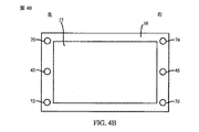
[0052]図4Bは、取り外されたフロントパネル15を有するフレーム16及びアクティブな表示パネル17を図式的に示す。示されるように、フレーム16は、アクティブな表示パネル17の全ての辺を包む。他の実施形態では、フレーム16は、アクティブな表示パネル17の上辺及び下辺ではなく左側および右側を包み得る。上で議論されるように、フロントパネル15は、2セットのマグネットペアの磁石の結合によって表示デバイス10に取り外し可能に固定され得る。図4B中に示されるように、2つのマグネット42及び46は、表示デバイス10のフレーム16に接着される。マグネット42及び46は、好ましくは表示デバイス10のフレーム16に接合されるが、他の粘着手段によって固定されてもよい。図示されるように、マグネット42及び46は、フレーム16の側面の中心点の範囲内に位置する。他の具体化では、低PSIの泡材80および84は、フロントパネル15の内側46に面する、マグネット42及び46に固定され得る。
[0052] FIG. 4B schematically shows the
[0053]多くの圧力検出器70、72、74および76は、表示パネル17の4隅の近くの、ディスプレイ10のフレーム16上又は、レッグ20及び25上(図示せず)に配置され得る。ディスプレイに関してのフロントパネル15の動きは、ユーザタッチの位置及びユーザコマンドのジェスチャの種類を判断するために分析され得る圧力信号を生成する。他の実施形態では、高PSIの泡材50、52、54および56は、フロントパネル15の内側に面する圧力検出器70、72、74および76の外側表面に接合され得る。1つの構成において、圧力検出器70、72、74および76は、14.7mmの直径の活動領域を有する、パーツ番号FSR402としてインターリンクエレクトロニクス(Interlink Electronics)によって割り振られた単一ゾーンの力センサ抵抗器であり得る。
[0053] A number of
[0054]フロントパネル15が、表示デバイス10に取り外し可能に固定されている場合、マグネット42および46は、フロントパネル15の内側で対応するマグネット40および44と一致させられた時、表示デバイスの15にフロントパネルの磁石の結合を供給する。例えば、マグネット42および44が、磁気的に引きつけられるように、マグネット40、42、44および46は適切な位置に置かれ、また、マグネット40および46は、表示デバイス10にフロントパネル15を付けるための磁石の結合を提供するために磁気的に引きつけられる。
[0054] If the
[0055]他の実施形態において、マグネットペアは、表示デバイス10のフレーム16のレッグ20および25の下辺または上辺に接近して配置され得る。1つの構成では、マグネットは、4.5lbsの付着力を有するK&Jマグネットによって割り当てられた製品番号D91−N52の、ネオジムディスクマグネットであり得る。フロントパネル15の重さに依存して、マグネット強さを変えること、あるいは一方当たり、1セット以上のマグネットが必要であり得る。
[0055] In other embodiments, the magnet pair may be placed close to the lower or upper side of the
[0056]マグネット40、42、44および46は、小さな隙間が、フロントパネル15とアクティブな表示パネル17との間に存在するように、表示デバイス10にフロントパネル15を固定にするよう構成される。フロントパネル15とアクティブな表示パネル17との間の小さな隙間は、表示パネル17、並びに圧力検出器70、72、74および76に対してフロントパネル15を動かすことを可能にする。したがって、フロントパネル15上のユーザ圧力は、高PSIの泡材50、52、54及び56に、力の変化量を備えた、対応する圧力検出器70、72、74及び76に圧力を加えさせるフロントパネルの動きを教える。フロントパネル15とアクティブな表示パネル17と、の間の隙間は、フロントパネル15の内側の破片或いは異物があるだろう、アクティブな表示パネル17を引っ掻くことから防止することをも助ける。その隙間は、さらにユーザによる、フロントパネル15の一般的な取り外しおよび配置に起因するアクティブな表示パネル17の掻き傷を防止することを助ける。いくつかの構成では、フロントパネル15とアクティブな表示パネル17と、の間の隙間は、約3mmであり得る。他の構成では、フロントパネル15とアクティブな表示パネルと、の間の隙間は、約2mm以下になり得る。
[0056] The
[0057]互いのマグネットペアのうちの1つのマグネットに固定される、低PSIの泡材80および84は、フロントパネル15が、ユーザタッチに対する圧縮反応中の表示パネル17に対して移動させるよう及び/または傾けられる(tilt)ようにし、また表示パネル17に対してフロントパネル15の動きを和らげられるようにする。低PSIの泡材80および84は、フロントパネル15上のユーザタッチの解除後に、フロントパネル15が、圧力検出器70、72、74、及び76に対してニュートラルの位置に戻って来られるようにするためバネとしても働く。低PSIの泡材80および84は、表示デバイス10にフロントパネル15を付着させるマグネットペアのうちのいずれか一方のマグネットに接合され得る。1つの構成では、低PSIの泡材80は、マグネット40を覆い、また接合され得、また、低PSIの泡材84は、フロントパネル15の内側のマグネット44を覆い、また接合され得る。他の構成では、低PSIの泡材80はマグネット42に接合され得る。また、低PSIの泡材84は、表示デバイス10のレッグ20および25の中心の近くに配置されたマグネット46に接合され得る。
[0057] Low PSI foams 80 and 84, secured to one magnet of each other's magnet pair, allow the
[0058]フロントパネル15が、ディスプレイ15に付着られている時、高PSIの泡材50、52、54及び56を、対応する圧力検出器70、72、74及び76と位置合わせする。ディスプレイ10のフロントパネル15上のユーザ圧力は、4つの検出器70、72、74及び76の各々からの圧力信号を生成するための対応する圧力検出器70、72、74及び76に接触して、高PSIの泡材50、52、54及び56に圧力を掛けるであろう。これらの信号は、より詳細に下で議論されるように、ユーザのフロントパネル15上のタッチの位置を判断するために分析され得る。信号は、なされたユーザジェスチャの種類、ユーザジェスチャに関連された関連コマンドを判断するために、或いはより詳しく下で議論されるように、赤外線のジェスチャ認識を活性化するために、分析もされ得る。
[0058] When the
[0059]さらにここで議論されるように、プロセッサは、圧力検出器70、72、74及び76からの信号を受信し、圧力信号をユーザジェスチャと関連させる。検知部は、検知部間での、相対的な圧力差に基づいてフロントパネル上のユーザタッチから圧力の位置を判断することができるように構成される。圧力検出器70、72、74及び76は、タッチセンサ式の表示デバイス10のフロントパネル15上でユーザ入力を受信する1つの手段を表示する。
[0059] As further discussed herein, the processor receives signals from the
[0060]表示デバイス10の断面図が図5に示される。この図は、表示デバイス10の右側に配置されたマグネットと圧力検出器を貫通する断面を示す。この図では、マグネット40および46は、表示デバイス10にフロントパネル15を固定するためにペアとされる。低PSIの泡材80は、ユーザのタッチからの圧力の解除の後、ニュートラルな位置にフロントパネル15を戻すためのバネとして機能させるためのマグネット40と46との間に挟まれる。図5は、1つの低PSIの泡材80を示す。しかしながら、対応する泡材84(図示せず)は、ディスプレイ10の反対側(左側)に配置される。
[0060] A cross-sectional view of
[0061]いくつかの実施形態では、サンドペーパのような高摩擦材料は、わずかに或いは滑ることのない表示デバイス10に固くフロントパネル15を固定するための各ペアのマグネット間で提供され得る。いくつかの構成では、高摩擦フィルム或いはサンドペーパは、フレームかレッグに付けられたマグネットと、フロントパネル15の内側46に固定されたマグネットに付着された低PSIの泡材と、の間で固定され得る。この高摩擦フィルムは、前面のガラスが下へ滑り、あるいは左右に滑ることから防止する。図5に示されるように、高摩擦フィルム材90はさらに、フロントパネル15で下に動いたり或いは左右への滑りを最小にするためにマグネット40と46との間に挟まれる。いくつかの構成では、高摩擦材料は、220のA−WTを有するノートンTufbak Gold T481のようなサンドペーパであり得る。フロントパネル15が洗浄される時、この高摩擦材料は、時間を通じて(over)繰り返される洗浄に耐え得る。さらに、この材料は泡材をはぎ取ることなく、低PSIの泡材を掴むのに十分に荒い。
[0061] In some embodiments, a high friction material, such as sandpaper, may be provided between each pair of magnets for rigidly securing the
[0062]それに応じて、ディスプレイ(図示せず)の反対側で、マグネット42および44は、低PSIの泡材84及びマグネット42と44との間に挟まれた第2の高摩擦フィルム材90を有する、表示デバイス10にフロントパネル15の固定を助けるペアである。低PSIの泡材80および84は、マグネット40、42、44および46が、泡とフィルムとを圧縮する時にぶつかって(into)、「かみつく」ための高摩擦材料90に関するグリップ面として機能する。
[0062] Accordingly, on the opposite side of the display (not shown), the
[0063]フロントパネル15とフレーム16との間の隙間95は、図5中でよりはっきり見られ得る。隙間95は、ユーザのタッチからの圧力に応じてアクティブな表示パネル17及びフレーム16に対してフロントパネル15が移動することを可能にする。
[0063] The
[0064]図5に示されるように、高PSIの泡材54及び56は、圧力検出器74及び76と位置合わせられる。ディスプレイ10に対するフロントパネル15の動きは、対応する圧力検出器に接触して、高PSIの泡材を圧縮し、各圧力検出器からの圧力信号を引き起こすだろう。フロントパネル15の動きは、高PSIの泡材に、対応する圧力検出器に接触して圧縮させ、或いは高PSIの泡状に、対応する圧力検出器から解除させ得る。
[0064] As shown in FIG. 5, high
[0065]例えば、ユーザが、ディスプレイの右上カドラント(quadrant)に触れ、圧力検出器74に対して(against)高PSIの泡材54を押す時、フロントパネル15の右上隅は、フレーム16の方に近づくであろう。フロントパネル15の剛性は、フロントパネル15のより低い右下隅に、フレーム16から離れるように上げさせるだろう。ユーザのタッチからの圧力に応じたフロントパネル15の動きは、ディスプレイ10の各サイド上の圧力検出器からの異なる応答をもたらすだろう。これらの応答は、ユーザタッチのフロントパネル15上の位置を判断するために分析され得、ユーザに選択されたアプリケーション内での所望のコマンドを実行するために、ユーザのタッチの位置でアクティブなウィンドウか特定のアプリケーションかに関連付けられ得る。
[0065] For example, when the user touches the upper right quadrant of the display and presses the
赤外線ジェスチャ捕捉特性の要旨
[0066]発明の1つの実施形態では、対話型のユーザジェスチャは、視覚的にユーザジェスチャを分析するための赤外線カメラ及び赤外線の光ユニットを使用する、タッチセンサ式の表示デバイス上で捕捉され得る。ディスプレイのフロントパネル上のユーザのタッチで加えられた圧力は、ディスプレイに搭載された少なくとも1つの圧力検出器によって測定されるように、対話型のジェスチャの開始を示し、表示デバイスに接続されたプロセッサ内に収容されたジェスチャ処理モジュールを有効化するために使用され得る。同様に、タッチセンサ式のディスプレイからの圧力の解除は、対話型のジェスチャが終了したことを示す。
Summary of infrared gesture capture characteristics
[0066] In one embodiment of the invention, an interactive user gesture may be captured on a touch-sensitive display device that uses an infrared camera and an infrared light unit to visually analyze the user gesture. . A processor connected to the display device, indicating the start of an interactive gesture, such that the pressure applied by a user touch on the front panel of the display is measured by at least one pressure detector mounted on the display It can be used to validate a gesture processing module contained within. Similarly, release of pressure from the touch-sensitive display indicates that the interactive gesture has ended.
[0067]図6は、ユーザジェスチャの赤外線の画像の捕捉の1つの実施形態を示す。電子筐体45に付けられた赤外線カメラ35は、プロセッサのジェスチャ認識モジュールによる解析に関する対話型のジェスチャの画像を捕捉することができる。1つの構成では、フロントパネル15上のユーザ圧力は、少なくとも1つの圧力検出器(図示せず)によって記録されると、赤外線カメラ35の有効化、及びフレーム16上の赤外線の光源からの赤外線の光源65の照明を引き起こし得る。
[0067] FIG. 6 illustrates one embodiment of capturing an infrared image of a user gesture. An
[0068]実線65によって示された赤外線の光源は、透明なアクティブな表示パネル17およびフロントパネル15を通り抜け得る。赤外線カメラ35は、ユーザの指55からの赤外線の反射75を捕捉するためにディスプレイの後ろの最適な場所に配置され得る。赤外線カメラ35は、表示パネル17が、ユーザジェスチャの画像を捕捉するためにアクティブで非アクティブの両者である場合、透明なアクティブな表示パネル17を通じて見得る。フロントパネル15からの圧力の解除は、圧力検出器によって判断された時、赤外線ジェスチャの認識機能の終了を信号で伝え、赤外線の光ユニットをターンオフされるように動作させ得る。
[0068] The infrared light source indicated by the
赤外線ジェスチャの命令システムの要旨
[0069]赤外線ジェスチャの認識で構成されるタッチセンサ式の表示デバイス10のハイレベルなブロック図が図7に示される。タッチセンサ式の表示システム10は、アクティブな表示パネル、バックライトLEDストリップ、赤外線の光ユニット8、赤外線カメラ35、あるいはディスプレイ10内で使用される他の電子コンポーネントのような、ディスプレイの機能を制御するための電子筐体45に組み込まれ得る。図示されるように、システム10は、多くの圧力検出器70、72、74及び76、並びにディスプレイ出力79にリンクされたプロセッサ120を含んでいるコンポーネントのセットを有する。赤外線カメラ35及び赤外線の光ユニット8もプロセッサ120にリンクされる。作業領域135及びメモリ140は、プロセッサ120とも通信され得る。タッチセンサ式の表示システム10は、ワード処理、ビデオ及びオーディオ機能、或いはインターネットを介した対話型のブラウジングのような、ディスプレイに関する追加のアプリケーションおよび機能を提供するために、コンピュータにも接続し得る。
Summary of instruction system for infrared gestures
[0069] A high level block diagram of a touch-
[0070]タッチセンサ式の表示システム10は、台所用食器棚ユニット、冷蔵庫、或いは他の電化製品に組み込まれたディスプレイのような静止しているデバイス、或いは、スタンドアロンの表示デバイスであり得る。多くのアプリケーションが、付属のコンピュータシステムを介してタッチセンサ式の表示システム10上でユーザに利用可能となり得る。これらのアプリケーションは、カレンダ表示、編集機能、ワード処理機能、レシピ編集及び表示機能、ビデオ及び画像表示機能、並びにインターネットブラウジング機能を含み得るが、これに限定するものではない。
[0070] The touch-
[0071]プロセッサ120は、汎用処理ユニット、または表示アプリケーションのために特別に設計されたプロセッサであり得る。図示されるように、プロセッサ120は、メモリ140および作業領域135に接続される。図解入りの実施形態において、メモリ140は、タッチ検出モジュール145、画像キャプチャモジュール146、ジェスチャの処理モジュール150、表示モジュール155、オペレーティングシステム160及びユーザインターフェースモジュール165を格納している。これらのモジュールは、様々なディスプレイ、タッチセンサ式、画像キャプチャ及びジェスチャ処理機能及びデバイス管理タスク、を実行するプロセッサ120を構成する命令を含み得る。作業領域135は、メモリ140のモジュール中に含まれているプロセッサ命令のワーキングセットを格納するためのプロセッサ120によって使用され得る。あるいは、作業領域135は、タッチセンサ式の表示システム10の動作中に生成された動的データを格納するためのプロセッサ120によっても使用され得る。
[0071] The
[0072]上述されるように、プロセッサ120は、メモリ140中に格納された幾つかのモジュールによって構成される。タッチ検出モジュール145は、圧力検出器70、72、74及び76から受信した信号を分析することにより、ユーザのディスプレイ10のフロントパネル15上のタッチを検知するためのプロセッサ120を構成する命令を含んでいる。したがって、タッチ検出モジュール145及び圧力検出器70、72、74及び76と一緒に、プロセッサ120は、表示デバイス10のフロントパネル15上のユーザタッチを検知するための1つの手段を表す。
[0072] As described above, the
[0073]画像キャプチャモジュール146は、赤外線カメラ35を使用して、ディスプレイ10のフロントパネル15上でなされたユーザジェスチャの画像を捕捉するためのプロセッサ120を構成する命令を提供する。フロントパネル15上のユーザタッチは、赤外線画像の捕捉機能の始動を動作させ得る。フロントパネル15からの圧力のユーザの解除は、赤外線画像の捕捉機能の中段を動作させ得る。
[0073] The
[0074]ジェスチャ処理モジュール150は、タッチ及び/又はジェスチャが意図する意味を判断するための捕捉された画像及び圧力検出器のデータを処理するためのプロセッサ120を構成する命令を提供する。ジェスチャ処理モジュール150は、例えば、色信号処理、デジタル・アナログ変換、および/またはガンマ補正を含む、受信された画像上で様々な機能を行うことができる。ジェスチャ処理モジュール150は、カメラ35から、ユーザの手または指を収めた一連の画像を受信することができ、ジェスチャ処理モジュール150は、鏡像を生成するためのそれぞれの画像を反転させるように構成されることができる。ジェスチャ処理モジュール150は、ジェスチャパターンマッチング又は特徴抽出のような、追加処理機能を実行するための反転及び/又は非反転画像を使用し得る。データは、メモリ140内の画像データとしても格納され得る。したがって、タッチ検出モジュール145、画像キャプチャモジュール146、圧力検出器70、72、74及び76、赤外線カメラ35並びにジェスチャ処理モジュール150と一緒に、プロセッサ120は、ユーザタッチの意図する意味を判断するための1つの手段を表す。
[0074] The
[0075]ジェスチャ処理モジュール150は、結合された画像を形成するための、処理され或いは処理されていない画像を組み合わせ得る。ジェスチャ処理モジュール150は、さらに動きの領域を判断するための一連の画像を処理するための特徴抽出機能を実行し得る。例えば、ジェスチャ処理モジュール150は、直接先行フレームのような、捕捉シーケンス中の前のフレームと受信フレームとを比較し、フレーム間の画像の違いを計算し得る。差異の画像は、例えば、フィルタにかけられた差異の画像を作り出すために、しきい値より下の差異を除去することなどにより、任意の適した方法でフィルタにかけられ得る。フィルタにかけられた、および/またはフィルタにかけられない差異の画像は、メモリ140に画像データとして記憶されることができる。
[0075]
[0076]ジェスチャの開始点は、表示画面に対してユーザによる初期画面のタッチの地理的位置を最初に計算することにより判断され得る。ジェスチャ処理モジュール150は、透明なパネルと通信する各圧力検出器から、及び表示パネルに対するユーザタッチの相対的な二次元の位置を判断したデータから、相対圧力を判断し得る。その判断は、システムによって判断されるようなジェスチャの開始点になることにより、赤外線カメラによってジェスチャの判断に追加の焦点を供給し得る。IR捕捉を、検出された最初のタッチ位置と位置合わせすることによって、ジェスチャ処理モジュールは、時間とともに(over)ジェスチャの開始および動きを判断し得る。
[0076] The starting point of the gesture may be determined by first calculating the geographic location of the initial screen touch by the user relative to the display screen. The
[0077]ユーザジェスチャの終点も、ジェスチャ処理モジュール150によって判断され得る。ジェスチャ処理モジュール150は、ジェスチャの終点を判断するための一連の異なる画像(the sequence of difference images)を分析し得、あるいは、ジェスチャの終点は、フロントパネル15に対するユーザ圧力の解除から判断され得る。例えば、ジェスチャ終点検出モジュール150は、比較的高い動きを収めた1つまたは複数の一連のフレームの後に検出された、比較的低い動きを有する1つまたは複数のフレームを探し出すように構成されることができる。ジェスチャの終点が検出されたと判断されると、ジェスチャ処理モジュール150は、ジェスチャが、1つまたは複数の既知のジェスチャパターンと一致するかどうか判断するための情報を使用し得る。例えば、一連のジェスチャの画像は、認識されたジェスチャが存在するかどうか判断するため、メモリ140に格納された各ジェスチャのテンプレートと比較され得る。
[0077] The end point of the user gesture may also be determined by the
[0078]ユーザインターフェースモジュール165は、表示デバイス10のアクティブな表示パネル17上に情報を表示するためのプロセッサ120を構成する命令を含み得る。
[0078] The
[0079]様々なモジュールは、ハードウェアおよび/またはソフトウェアの様々な組み合わせで履行され得る。例えば、タッチ検出モジュール145、画像キャプチャモジュール146、ジェスチャ処理モジュール150、ディスプレイモジュール155及びユーザインターフェースモジュール165は、1つまたは複数のプロセッサを使用して実行するように構成されたコンピュータ可読記憶媒体上に格納された命令として履行され得る。モジュールの履行に関する追加の詳細は、後に以下で詳しく説明されることになる。
[0079] Various modules may be implemented in various combinations of hardware and / or software. For example, the
[0080]オペレーティングシステム160は、システム10のメモリおよび処理リソースを管理するためのプロセッサ120を構成する。例えば、オペレーティングシステム160は、ディスプレイ出力、圧力検出器70、72、74及び76、並びに赤外線カメラ35のような、ハードウェアリソースを管理するためのデバイスドライバを含み得る。したがって、いくつかの実施形態では、上述されたタッチセンサ式の表示システムモジュール中に含まれる命令は、これらのハードウェアリソースと直接情報をやりとりし得ないが、代わりに、オペレーティングシステムコンポーネント160中に配置された、標準サブルーチンあるいはAPIを通じて情報のやりとりをし得る。その後、オペレーティングシステム160内の命令は、これらのハードウェアコンポーネントと直接情報のやり取りをし得る。
[0080] The
[0081]図7は、プロセッサ、多くの圧力検出器、電子表示ディスプレイ出力、及びメモリを含めるための個別のコンポーネントを備えたデバイスを描写しているが、当業者は、これらの個別のコンポーネントは、特定の設計目的を達成するための様々な方法で組み合わせられ得ることを認識するだろう。例えば、代替の実施形態では、メモリコンポーネントは、費用を節約しパフォーマンスを向上させるために、プロセッサコンポーネントと組み合わされ得る。 [0081] Although FIG. 7 depicts a device with a processor, a number of pressure detectors, an electronic display display output, and individual components to include a memory, those skilled in the art will recognize these individual components as It will be appreciated that they can be combined in various ways to achieve a particular design objective. For example, in an alternative embodiment, the memory component can be combined with the processor component to save money and improve performance.
[0082]加えて、図7は、作業領域を備える個別のメモリ135及びいくつかのモジュールを具備するメモリコンポーネント140を含む、2つのメモリコンポーネントを示すが、当業者は、異なるメモリ構造を利用するいくつかの実施形態を認識するだろう。例えば、設計は、メモリ140中に含まれるモジュールを履行するプロセッサ命令の記憶装置に関するスタティックRAM或いはROMを利用し得る。その代替案としては、プロセッサ命令は、外部デバイスポート経由或いはタッチセンサ式の表示システム10中に集積されている磁気ディスク装置からのシステムスタートアップで読まれ得る。その後、プロセッサ命令は、RAMにロードされて、プロセッサによる実行を容易にし得る。例えば、作業領域135は、プロセッサ120による実行の前に作業領域135にロードされた命令を備える、RAMメモリであり得る。
[0082] In addition, although FIG. 7 shows two memory components, including a
赤外線ジェスチャ相互作用の要旨
[0083]図8は、表示デバイス10のようなタッチセンサ式の電子表示上で履行され得る認識処理、及び赤外線ジェスチャ捕捉の要旨を示す処理800を図示する高レベルのフローチャートである。プロセス800は、いくつかの実施形態において、表示デバイス10のフロントパネル15上でなされるユーザジェスチャの一連の画像又は1つの画像を捕捉するため、また指示されたユーザジェスチャとしてそれらの画像又はこの1つの画像を解釈するために使用され得る。
Summary of infrared gesture interaction
[0083] FIG. 8 is a high-level flowchart illustrating a recognition process that may be implemented on a touch-sensitive electronic display, such as
[0084]プロセス800は、スタートブロック805で開始し、ブロック810へ推移し、ここにおいて1つまたは複数の圧力検出器は、ユーザがディスプレイのフロントパネルの上にかれらの手や指を置いたということを示すための圧力信号を送信する。フロントパネル上でユーザのタッチの位置によって、圧力検出器からの信号は変わり得る。フロントパネル上のユーザタッチは、フロントパネルに、ディスプレイのフレームに付けられたアクティブな表示パネルの方へ(toward)それさせ得る。同様に、このそらすことは、圧力検出器に、対応する高PSIの泡材によって角度を変化させることに関与させる。
[0084] The
[0085]フロントパネルとアクティブな表示パネルとの間の小さなギャップと一緒に、表示デバイスにフロントパネルを固定するそれぞれのマグネットペア間に低PSIの泡材を挿入することは、フロントパネルが上下にそらすことを可能にする。表示デバイスの中心を垂直に通過する中心線の一方サイドでのユーザタッチの位置は、さらにフロントパネルに、他よりも片側にもっとそれさせ得、従って、フロントパネル上のユーザタッチのエリアにより近く配置された圧力検出器においてより大きな圧力信号応答を引き起こす。同様に、フロントパネルの4カドラントのうちのいずれかのユーザタッチは、ユーザタッチのエリアにもっとも近いセンサからのより高圧力センサ応答をもたらすであろう。 [0085] Inserting a low PSI foam material between each pair of magnets that secure the front panel to the display device, along with a small gap between the front panel and the active display panel, makes the front panel up and down Makes it possible to deflect. The position of the user touch on one side of the center line that passes vertically through the center of the display device can be further diverted to the front panel and to one side more than the other, and therefore closer to the user touch area on the front panel Cause a greater pressure signal response in the connected pressure detector. Similarly, a user touch of any of the four quadrants on the front panel will result in a higher pressure sensor response from the sensor closest to the user touch area.
[0086]その後、プロセス800は、ブロック815に推移し、ここにおいて赤外線の光ユニットが、フロントパネル上のユーザタッチを示す圧力信号に応じてターンオンするために指示される。同時に、赤外線カメラは、表示デバイスのフロントパネル上でなされたユーザジェスチャの1つまたは複数の画像を捕捉することを始めるように指示される。
[0086] The
[0087]赤外線の光ユニット及び赤外線カメラがターンオンした後、プロセス800はブロック820に推移し、ここにおいて、フロントパネル上のユーザタッチの位置が判断される。ユーザタッチ或いはジェスチャのそれぞれについて、タッチ期間、タッチのあらゆる動きの経路又は方向、及びタッチの動きのあらゆる速度が判断され得る。ユーザタッチの位置は、複数の圧力検出器の各々の間の距離、既知の位置、並びにプロセッサによって受信した圧力信号の大きさから判断され得る。ユーザタッチの位置は、表示デバイスに(with)ユーザの意思疎通の文脈を示し得る。例えば、ユーザタッチの位置は、表示デバイス上の各アプリケーションの表示された位置に依存して、ユーザが、インターネットブラウザウィンドウあるいは文書編集アプリケーションと交流していることを示し得る。
[0087] After the infrared light unit and the infrared camera are turned on, the
[0088]フロントパネル上のユーザタッチの位置を判断し、ユーザジェスチャの少なくとも1つの画像を得た後、プロセス800は、ブロック825へ推移し、ここにおいて、フロントパネル上のユーザによってなされたユーザジェスチャのタイプが判断される。ユーザジェスチャのタイプは、メモリユニット内に含まれるユーザジェスチャのカタログ或いは書庫と、ユーザジェスチャの一連の画像から形成された組み合わせられた画像或いはユーザジェスチャの画像と、を比較することによって判断され得る。
[0088] After determining the position of the user touch on the front panel and obtaining at least one image of the user gesture, the
[0089]一旦、ユーザジェスチャのタイプが判断されると、プロセス800は、ブロック830に推移し、ここにおいてユーザジェスチャは、所望の事前に定義されたコマンドに関連付けられる。例えば、ユーザは、フロントパネル上の1つの位置で指を滑らせる動作を実行でき、システムは、実行された動作を、アクティブな表示パネル上のオブジェクトを移動させること、に関連付けるだろう。マルチタッチジェスチャを含む、他の動作は、他の動作と一緒になって、アプリケーションを閉じたり開いたりすること、物のサイズを変えること、物を選択すること、或いは仮想キーボード上で文章を入力すること、のようなことも可能である。
[0089] Once the type of user gesture is determined, the
[0090]ユーザジェスチャのタイプを所望の事前に定義されたコマンドと関連付けた後、プロセス800は、ブロック835に推移し、ここにおいて、システムは、事前に定義されたコマンドを実行する。上記の例で議論されるように、システムは、事前に定義されたコマンドに関連付けられたジェスチャに応じて、他の動作と一緒になって、アプリケーションを開き又は閉じ、物のサイズを変更し、物を選択し、アプリケーションへの文章を入力し得る。一旦、事前に定義されたコマンドが実行されると、プロセス800は、ブロック840に推移し、次いで終了する。
[0090] After associating the type of user gesture with the desired predefined command, the
赤外線ジェスチャの捕捉及び識別の要旨
[0091]図9は、1つの実施形態に従った、赤外線カメラを使用して捕捉された複雑なユーザジェスチャ或いはマルチタッチを認識し、処理することに関するプロセス900のフローチャートである。プロセス900は、ブロック905でスタートし、次いでブロック910へ推移し、ここにおいて、システムは、ディスプレイのフロントパネル上でなされた一連の指又は手の画像を捕捉する。画像の捕捉は、ユーザが手か指で表示デバイスのフロントパネルに圧力を掛けた時に始まる。
Summary of infrared gesture capture and identification
[0091] FIG. 9 is a flowchart of a
[0092]上述されたように、タッチセンサ式のディスプレイへの圧力は、1つまたは複数の圧力検出器によって記録されると、ターンオンされるべき赤外線光ユニット、及び開始されるべき赤外線カメラによる画像捕捉を動作させる。ユーザが、彼または彼女の手か指を上げることによりディスプレイのフロントパネルから圧力を解除する時、画像捕捉の終了、及び複雑なマルチタッチのジェスチャの完成が示される。フロントパネルからの圧力の解除に際して、赤外線の光ユニットはターンオフされ、赤外線カメラによる画像捕捉が終了する。 [0092] As described above, when the pressure on the touch-sensitive display is recorded by one or more pressure detectors, the infrared light unit to be turned on and the image from the infrared camera to be initiated Activate capture. When the user releases pressure from the front panel of the display by raising his or her hand or finger, the end of image capture and completion of a complex multi-touch gesture is indicated. When releasing the pressure from the front panel, the infrared light unit is turned off, and the image capture by the infrared camera is completed.
[0093]その後、プロセス900は、ブロック915に推移し、ここにおいて、一連の画像は、画像処理機能を使用して、複雑なユーザジェスチャの単一の画像に組み合わされる。プロセス900、その後、ブロック920に推移し、ここにおいて、ユーザ入力に関連付けられたアプリケーションが特定される。そのアプリケーションは、1つまたは複数の圧力検出器によって特定されるように、表示ディスプレイ上のアプリケーションインタフェースの既知の位置、及びユーザタッチの既知の場所に基づいて特定され得る。
[0093] The
[0094]プロセス900は次に、ブロック925へ推移し、ここにおいて、1つまたは複数の候補のジェスチャ及び信頼因子が、ユーザジェスチャの組み合わされた画像を使用して判断される。例えば、ジェスチャの認識テンプレートは、捕捉された画像または複数の画像と比較され得る。各ジェスチャ認識テンプレートと、捕捉された1つの画像又は複数の画像との比較は、1つ以上の可能性があるジェスチャマッチをもたらし得る。可能性があるジェスチャマッチはそれぞれ、捕捉された1つの画像又は複数の画像に対するジェスチャ認識テンプレートの類似性に基づいて信頼因子を割り当てられ得る。しきい値信頼レベルを超える可能性のあるジェスチャマッチのような、十分な信頼因子の可能性のあるジェスチャマッチは、候補ジェスチャであるべきと判断され得る。候補ジェスチャ及びそれぞれのジェスチャ認識テンプレートを使用して決定された対応する信頼要因は、候補ジェスチャのリスト及び信頼要因を集合的に形成し得る。
[0094] The
[0095]候補ジェスチャ及び確信要因のリストを決定した後に、その後、プロセス800はブロック930に推移し、ここにおいて、誤検出が除去される。例えば、誤検出の除去は、大域的運動条件、局所的運動条件、および/または1つまたは複数の信頼要因を使用する、候補ジェスチャのリストからの1つまたは複数の候補ジェスチャの除去を含むことができる。誤検出であることとして削除されない候補ジェスチャは、プロセス900の次のブロック935中の認識されたジェスチャであると決定され得る。その後、プロセス900は、ブロック940に推移し、終了する。
[0095] After determining the list of candidate gestures and confidence factors, the
専門用語に関する説明
[0096]当業者であれば、ここで開示された履行に関連して説明された様々な例示的な論理ブロック、モジュール、回路、およびプロセスステップは、電子ハードウェア、コンピュータソフトウェア、または両方の組み合せとして履行されうることもさらに理解するであろう。ハードウェアとソフトウェアのこの互換性を明確に例示するために、様々な例示的なコンポーネント、ブロック、モジュール、回路、およびステップが、概してそれらの機能の点から上記に説明されてきた。このような機能性が、ハードウェアまたはソフトウェアとして履行されるか否かは、システム全体に課せられている、特定のアプリケーションおよび設計制約に依存する。当業者は、各特定のアプリケーションのために、様々な方法で、説明された機能を実装し得るが、そのような履行の判定は、本発明の範囲から逸脱を引き起こしていると解釈されるべきでない。当業者であれば、部分、または一部が、全体よりも少ないもの、または全体に等しいものを備え得ることを理解するであろう。例えば、画素のコレクションの部分は、それら画素のサブコレクションを称しうる。
Explanation of technical terms
[0096] Those skilled in the art will recognize that the various exemplary logic blocks, modules, circuits, and process steps described in connection with the implementations disclosed herein are electronic hardware, computer software, or a combination of both. It will be further understood that can be implemented as: To clearly illustrate this interchangeability of hardware and software, various illustrative components, blocks, modules, circuits, and steps have been described above generally in terms of their functionality. Whether such functionality is implemented as hardware or software depends upon the particular application and design constraints imposed on the overall system. Those skilled in the art may implement the described functionality in a variety of ways for each particular application, but such performance decisions should be construed as causing deviations from the scope of the present invention. Not. One skilled in the art will appreciate that a part, or part, may comprise less than or equal to the whole. For example, a portion of a collection of pixels can refer to a sub-collection of those pixels.
[0097]ここに開示された履行に関連して記載されたさまざまな例示的な論理ブロック、モジュール、および回路は、汎用プロセッサ、デジタル信号プロセッサ(DSP)、特定用途向け集積回路(ASIC)、フィールド・プログラマブル・ゲート・アレイ(FPGA)または他のプログラマブル論理デバイス、離散ゲートまたはトランジスタ論理、離散ハードウェア・コンポーネント、または、ここに説明される機能を実行するように設計されたこれら任意の組み合わせとともに実現または実行され得る。汎用プロセッサは、マイクロプロセッサであり得るが、代替において、このプロセッサは、任意の従来型のプロセッサ、コントローラ、マイクロコントローラ、またはステートマシン(state machine)でありうる。プロセッサは、また、例えば、DSPと、1つのマクロプロセッサ、複数のマイクロプロセッサ、DSPコアに結合した1つまたは複数のマイクロプロセッサ、その他の上記構成の組み合わせといった計算デバイスの組み合わせとしても実現されうる。 [0097] Various exemplary logic blocks, modules, and circuits described in connection with the implementations disclosed herein are general purpose processors, digital signal processors (DSPs), application specific integrated circuits (ASICs), fields Implemented with a programmable gate array (FPGA) or other programmable logic device, discrete gate or transistor logic, discrete hardware components, or any combination of these designed to perform the functions described herein Or it can be implemented. A general purpose processor may be a microprocessor, but in the alternative, the processor may be any conventional processor, controller, microcontroller, or state machine. The processor can also be implemented as a combination of computing devices such as a DSP and one macro processor, a plurality of microprocessors, one or more microprocessors coupled to a DSP core, and other combinations of the above configurations.
[0098]ここで開示された履行に関連して説明された方法または処理のステップは、ハードウェアで直接的に、プロセッサによって実行されるソフトウェアモジュールで、または両者の組み合わせで具現化されることができる。ソフトウェアモジュールは、RAMメモリ、フラッシュメモリ、ROMメモリ、EPROMメモリ、EEPROM(登録商標)メモリ、レジスタ、ハードディスク、リムーバルディスク、CD−ROM、または当該技術分野において周知のその他任意の形状の非一時的な記憶媒体内に存在し得る。典型的なコンピュータ可読記憶媒体は、プロセッサがコンピュータ可読記憶媒体から情報を読み取り、またそれに情報を書き込むことができるように、プロセッサに結合される。あるいは、記憶媒体はプロセッサに集積され得る。プロセッサおよび記憶媒体はASICに存在しうる。ASICは、ユーザ端末、カメラ、または他のデバイス内に存在し得る。代替において、プロセッサおよび記憶媒体は、ユーザ端末、カメラ、または他のデバイス内のディスクリートコンポーネントとして存在し得る。 [0098] The method or process steps described in connection with the implementations disclosed herein may be embodied directly in hardware, in a software module executed by a processor, or in a combination of both. it can. The software module can be RAM memory, flash memory, ROM memory, EPROM memory, EEPROM® memory, registers, hard disk, removable disk, CD-ROM, or any other non-transitory shape known in the art. It can exist in a storage medium. An exemplary computer readable storage medium is coupled to the processor such that the processor can read information from, and write information to, the computer-readable storage medium. In the alternative, the storage medium may be integral to the processor. A processor and a storage medium may reside in the ASIC. The ASIC may reside in a user terminal, camera, or other device. In the alternative, the processor and the storage medium may reside as discrete components in a user terminal, camera, or other device.
[0099]見出しは、参照のためおよび様々なセクションの位置付けを支援するために、ここに含まれる。これらの見出しは、これらに関して説明された概念の範囲を限定するようには意図されない。このような概念は、明細書全体にわたって適用性を有し得る。 [0099] Headings are included here for reference and to assist in positioning the various sections. These headings are not intended to limit the scope of the concepts described in these regards. Such a concept may have applicability throughout the specification.
[0100]開示の実現の先の説明は、いずれの当業者でも本発明を作り出し、使用することを可能にさせるために提供されている。これらの履行への様々な修正は、当業者にとって容易に明白であり、ここに定義された一般的な原理は、本発明の主旨または範囲から逸脱することなく、他の履行にも適用されうる。したがって、本発明は、ここに示された履行に限定されるようには意図されず、ここに開示される原理および新規な特徴と一致する最も広い範囲を与えられることとなる。 [0100] The previous description of the implementation of the disclosure is provided to enable any person skilled in the art to make and use the invention. Various modifications to these implementations will be readily apparent to those skilled in the art, and the general principles defined herein may be applied to other implementations without departing from the spirit or scope of the invention. . Accordingly, the present invention is not intended to be limited to the implementations shown herein but is to be accorded the widest scope consistent with the principles and novel features disclosed herein.
[0100]開示の実現の先の説明は、いずれの当業者でも本発明を作り出し、使用することを可能にさせるために提供されている。これらの履行への様々な修正は、当業者にとって容易に明白であり、ここに定義された一般的な原理は、本発明の主旨または範囲から逸脱することなく、他の履行にも適用されうる。したがって、本発明は、ここに示された履行に限定されるようには意図されず、ここに開示される原理および新規な特徴と一致する最も広い範囲を与えられることとなる。 [0100] The previous description of the implementation of the disclosure is provided to enable any person skilled in the art to make and use the invention. Various modifications to these implementations will be readily apparent to those skilled in the art, and the general principles defined herein may be applied to other implementations without departing from the spirit or scope of the invention. . Accordingly, the present invention is not intended to be limited to the implementations shown herein but is to be accorded the widest scope consistent with the principles and novel features disclosed herein.
以下、出願当初の特許請求の範囲を付記する。 Hereinafter, the scope of claims at the beginning of application will be added.
[付記1] [Appendix 1]
全面及び背面を有し、ユーザのタッチを検知可能なタッチスクリーンと、 A touch screen having a whole surface and a back surface and capable of detecting a user's touch;
前記タッチスクリーンの前に置かれたユーザ指に光を当てるように構成された1つまたは複数の赤外線の光源と、 One or more infrared light sources configured to illuminate a user finger placed in front of the touch screen;
前記タッチスクリーンの背面に配置され、前記タッチスクリーンを通じてユーザの指の赤外線画像を捕捉するよう構成された赤外線カメラと、 An infrared camera disposed on the back of the touch screen and configured to capture an infrared image of a user's finger through the touch screen;
ユーザが前記タッチスクリーンに触れた時に活性化するよう構成されたジェスチャ認証モジュールと、 A gesture authentication module configured to be activated when a user touches the touch screen;
前記ユーザの指の前記位置を追跡し前記タッチスクリーン上のユーザのタッチを判断するように構成されたジェスチャ処理モジュールと、を備え、 A gesture processing module configured to track the position of the user's finger and determine a user's touch on the touch screen;
ここにおいて、前記ジェスチャ処理モジュールは、前記判断されたタッチ及び位置の追跡からユーザジェスチャを判断する、 Wherein the gesture processing module determines a user gesture from the determined touch and position tracking;
タッチセンサ式の表示デバイス。 Touch-sensitive display device.
[付記2] [Appendix 2]
前記タッチスクリーンは、フレーム構造上に搭載される、付記1の表示デバイス。 The display device according to appendix 1, wherein the touch screen is mounted on a frame structure.
[付記3] [Appendix 3]
前記タッチスクリーンは、前記フレーム構造上に搭載され、情報を表示するよう構成された第1パネル、及び前記第1パネルに取り外し可能に固定され、前記第1パネルをカバーするように構成された第2パネルを具備する付記2の表示デバイス。 The touch screen is mounted on the frame structure and configured to display information and is removably fixed to the first panel and configured to cover the first panel. The display device of
[付記4] [Appendix 4]
前記フレーム構造に結合され、前記第2パネル上のユーザのタッチの位置を判断するよう構成された、少なくとも1つの圧力センサを更に具備する、付記3の表示デバイス。 The display device of
[付記5] [Appendix 5]
前記第2パネルは、多数のマグネットにより前記第1パネルに取り外し可能に固定されている、付記3の表示デバイス。 The display device according to
[付記6] [Appendix 6]
前記赤外線の光源は、前記第1及び第2パネルの背面の前記フレーム構造に結合され、前記ディスプレイのユーザに対して前記第1及び前記第2パネルを通じて光を向けるように構成される、付記3の表示デバイス。 The infrared light source is coupled to the frame structure on the back of the first and second panels and is configured to direct light through the first and second panels to a user of the display. Display device.
[付記7] [Appendix 7]
前記赤外線カメラは、前記第1及び第2パネルの背面の前記フレーム構造に結合される、付記3の表示デバイス。 The display device according to
[付記8] [Appendix 8]
前記赤外線の光源は、前記第2パネル上のタッチイベントに応答してターンオンするよう構成される、付記4の表示デバイス。 The display device of claim 4, wherein the infrared light source is configured to turn on in response to a touch event on the second panel.
[付記9] [Appendix 9]
前面及び背面を有し、ユーザのタッチを検知可能なタッチスクリーンと、 A touch screen having a front surface and a back surface and capable of detecting a user's touch;
前記タッチスクリーンの前に置かれたユーザの指に光を当てるように構成された1つまたは複数の赤外線の光源と、 One or more infrared light sources configured to illuminate a user's finger placed in front of the touch screen;
前記タッチスクリーンの背面に配置され、前記タッチスクリーンを通じてユーザの指の赤外線画像を捕捉するよう構成された赤外線カメラと、を具備し、 An infrared camera disposed on the back of the touch screen and configured to capture an infrared image of a user's finger through the touch screen;
制御モジュールは、 The control module
ユーザが前記タッチスクリーンをタッチした時、ジェスチャ認証モジュールを活性化し、 When the user touches the touch screen, the gesture authentication module is activated,
タッチセンサ式の表示デバイスの前記タッチスクリーン上で作られたユーザジェスチャの1つまたは複数の画像を捕捉し、 Capturing one or more images of a user gesture made on the touch screen of a touch-sensitive display device;
ユーザが前記タッチスクリーンを離した時、前記ジェスチャ認証モジュールの動作を停止させ、 When the user releases the touch screen, the operation of the gesture authentication module is stopped,
前記ディスプレイ上の対応する動作を実行するためにユーザジェスチャの画像を解析する、ように構成された、前記タッチセンサ式の表示デバイス上のユーザジェスチャを捕捉するためのシステム。 A system for capturing a user gesture on the touch-sensitive display device configured to analyze an image of a user gesture to perform a corresponding action on the display.
[付記10] [Appendix 10]
前記タッチスクリーンは、フレーム構造上に搭載される、付記9のシステム。 The system according to appendix 9, wherein the touch screen is mounted on a frame structure.
[付記11] [Appendix 11]
前記タッチスクリーンは、前記フレーム構造上に搭載され、情報を表示するよう構成された第1パネル、及び前記第1パネルに対して取り外し可能に固定され、前記第1パネルをカバーするように構成された第2パネル、を具備する、付記10のシステム。 The touch screen is mounted on the frame structure and configured to cover the first panel so as to be detachably fixed to the first panel and configured to display information. The system of
[付記12] [Appendix 12]
前記制御モジュールは、前記ユーザジェスチャの前記画像に関連されたユーザコマンドに関するメモリに問い合わせするよう、更に構成された、付記9のシステム。 The system of claim 9, wherein the control module is further configured to query a memory for user commands associated with the image of the user gesture.
[付記13] [Appendix 13]
前記制御モジュールは、プロセッサを介して前記ユーザコマンドを実行するよう、更に構成された、付記12のシステム。 The system of claim 12, wherein the control module is further configured to execute the user command via a processor.
[付記14] [Appendix 14]
前記ユーザジェスチャの前記画像に関連された前記ユーザコマンドに関する前記問い合わせは、識別されるジェスチャパターンに基づいている、付記12のシステム。 The system of claim 12, wherein the query for the user command associated with the image of the user gesture is based on an identified gesture pattern.
[付記15] [Appendix 15]
全面及び背面を有し、ユーザのタッチを検知可能なタッチスクリーンと、 A touch screen having a whole surface and a back surface and capable of detecting a user's touch;
ユーザが前記タッチスクリーンをタッチした時、赤外線の光源を供給する手段と、 Means for supplying an infrared light source when a user touches the touch screen;
タッチセンサ式の表示デバイスの前記タッチスクリーン上でなされたユーザジェスチャの1つまたは複数の画像を捕捉する手段と、 Means for capturing one or more images of a user gesture made on the touch screen of a touch-sensitive display device;
ユーザが前記タッチスクリーンを離した時、ユーザジェスチャの画像の捕捉を中断し、前記赤外線の光源の使用を停止する手段と、 Means for interrupting capture of an image of a user gesture when the user releases the touch screen and stopping the use of the infrared light source;
前記ディスプレイ上の対応する動作を実行するためのユーザジェスチャの前記画像を解析する手段と、を具備する前記タッチセンサ式の表示デバイス。 Means for analyzing the image of a user gesture for performing a corresponding action on the display, the touch-sensitive display device.
[付記16] [Appendix 16]
1つまたは複数の画像を捕捉する前記手段は、赤外線カメラを具備する、付記15のデバイス。
[付記17] [Appendix 17]
赤外線の光源を提供する前記手段は、前記タッチスクリーンを通じて光を光らせるように構成された、1つまたは複数の赤外線の光源を備える、付記15のデバイス。 The device of
[付記18] [Appendix 18]
タッチセンサ式の電子デバイス内にデータを入力するための方法であって、 A method for inputting data into a touch-sensitive electronic device, comprising:
前記タッチセンサ式のデバイス上のユーザタッチから圧力を検知することと、 Detecting pressure from a user touch on the touch-sensitive device;
ユーザタッチが検出されると、赤外線の光源を有効にすることと、 When a user touch is detected, enabling an infrared light source;
前記タッチセンサ式の表示デバイス上でなされたユーザジェスチャの1つまたは複数の画像を捕捉することと、 Capturing one or more images of a user gesture made on the touch-sensitive display device;
前記タッチセンサ式の電子デバイスの表示上の対応する動作を実行するためのユーザジェスチャの前記画像を解析することと Analyzing the image of a user gesture for performing a corresponding operation on a display of the touch-sensitive electronic device;
具備する、方法。 A method comprising.
[付記19] [Appendix 19]
ユーザジェスチャの前記画像を解析することは、前記画像を、少なくとも1つの候補のジェスチャを特定するための、複数のジェスチャ認証テンプレートのそれぞれと比較する、付記18の方法。 The method of
[付記20] [Appendix 20]
信頼要因を、それぞれの候補のジェスチャに割り当てること、をさらに備える、付記19に記載の方法。 The method of claim 19, further comprising assigning a confidence factor to each candidate gesture.
[付記21] [Appendix 21]
前記ジェスチャを解析することは、最も大きい前記信頼要因を有する少なくとも1つの候補のジェスチャから1つのジェスチャを選択することを備える、付記20に記載の方法。 24. The method of
[付記22] [Appendix 22]
プロセッサによって実行されると、タッチセンサ式の電子デバイス内にデータを入力する方法を実行する命令を具備する非一時的なコンピュータ可読記憶媒体であって、前記方法は、 When executed by a processor, a non-transitory computer readable storage medium comprising instructions for performing a method for inputting data into a touch-sensitive electronic device, the method comprising:
前記タッチセンサ式のデバイス上のユーザタッチから圧力を検知することと、 Detecting pressure from a user touch on the touch-sensitive device;
ユーザタッチが検出されると、赤外線の光源を有効にすることと、 When a user touch is detected, enabling an infrared light source;
前記タッチセンサ式の表示デバイス上でなされたユーザジェスチャの1つまたは複数の画像を捕捉することと、 Capturing one or more images of a user gesture made on the touch-sensitive display device;
前記タッチセンサ式の電子デバイスの表示上の、対応する動作を実行するためのユーザジェスチャの前記画像を解析することと Analyzing the image of a user gesture for performing a corresponding operation on the display of the touch-sensitive electronic device;
を具備する非一時的なコンピュータ可読記憶媒体。 A non-transitory computer-readable storage medium.
[付記23] [Appendix 23]
ユーザジェスチャの前記画像を解析することは、前記画像を、少なくとも1つの候補のジェスチャを特定するための複数のジェスチャ認証テンプレートのそれぞれと比較する、付記22のコンピュータ可読記憶媒体。 The computer readable storage medium of appendix 22, wherein analyzing the image of a user gesture compares the image to each of a plurality of gesture authentication templates for identifying at least one candidate gesture.
Claims (23)
前記タッチスクリーンの前に置かれたユーザ指に光を当てるように構成された1つまたは複数の赤外線の光源と、
前記タッチスクリーンの背面に配置され、前記タッチスクリーンを通じてユーザの指の赤外線画像を捕捉するよう構成された赤外線カメラと、
前記ユーザの指の前記位置を追跡し前記タッチスクリーン上のユーザのタッチを判断するように構成されたジェスチャ処理モジュールと、を備え、
ここにおいて、前記ジェスチャ処理モジュールは、前記判断されたタッチ及び位置の追跡からユーザジェスチャを判断する、
タッチセンサ式の表示デバイス。 A touch screen having a whole surface and a back surface and capable of detecting a user's touch;
One or more infrared light sources configured to illuminate a user finger placed in front of the touch screen;
An infrared camera disposed on the back of the touch screen and configured to capture an infrared image of a user's finger through the touch screen;
A gesture processing module configured to track the position of the user's finger and determine a user's touch on the touch screen;
Wherein the gesture processing module determines a user gesture from the determined touch and position tracking;
Touch-sensitive display device.
前記タッチスクリーンの前に置かれたユーザの指に光を当てるように構成された1つまたは複数の赤外線の光源と、
前記タッチスクリーンの背面に配置され、前記タッチスクリーンを通じてユーザの指の赤外線画像を捕捉するよう構成された赤外線カメラと、を具備し、
制御モジュールは、
ユーザが前記タッチスクリーンをタッチした時、ジェスチャ認証モジュールを活性化し、
タッチセンサ式の表示デバイスの前記タッチスクリーン上で作られたユーザジェスチャの1つまたは複数の画像を捕捉し、
ユーザが前記タッチスクリーンを離した時、前記ジェスチャ認証モジュールの動作を停止させ、
前記ディスプレイ上の対応する動作を実行するためにユーザジェスチャの画像を解析する、ように構成された、前記タッチセンサ式の表示デバイス上のユーザジェスチャを捕捉するためのシステム。 A touch screen having a front surface and a back surface and capable of detecting a user's touch;
One or more infrared light sources configured to illuminate a user's finger placed in front of the touch screen;
An infrared camera disposed on the back of the touch screen and configured to capture an infrared image of a user's finger through the touch screen;
The control module
When the user touches the touch screen, the gesture authentication module is activated,
Capturing one or more images of a user gesture made on the touch screen of a touch-sensitive display device;
When the user releases the touch screen, the operation of the gesture authentication module is stopped,
A system for capturing a user gesture on the touch-sensitive display device configured to analyze an image of a user gesture to perform a corresponding action on the display.
ユーザが前記タッチスクリーンをタッチした時、赤外線の光源を供給する手段と、
タッチセンサ式の表示デバイスの前記タッチスクリーン上でなされたユーザジェスチャの1つまたは複数の画像を捕捉する手段と、
ユーザが前記タッチスクリーンを離した時、ユーザジェスチャの画像の捕捉を中断し、前記赤外線の光源の使用を停止する手段と、
前記ディスプレイ上の対応する動作を実行するためのユーザジェスチャの前記画像を解析する手段と、を具備する前記タッチセンサ式の表示デバイス。 A touch screen having a whole surface and a back surface and capable of detecting a user's touch;
Means for supplying an infrared light source when a user touches the touch screen;
Means for capturing one or more images of a user gesture made on the touch screen of a touch-sensitive display device;
Means for interrupting capture of an image of a user gesture when the user releases the touch screen and stopping the use of the infrared light source;
Means for analyzing the image of a user gesture for performing a corresponding action on the display, the touch-sensitive display device.
前記タッチセンサ式のデバイス上のユーザタッチから圧力を検知することと、
ユーザタッチが検出されると、赤外線の光源を有効にすることと、
前記タッチセンサ式の表示デバイス上でなされたユーザジェスチャの1つまたは複数の画像を捕捉することと、
前記タッチセンサ式の電子デバイスの表示上の対応する動作を実行するためのユーザジェスチャの前記画像を解析することと
具備する、方法。 A method for inputting data into a touch-sensitive electronic device, comprising:
Detecting pressure from a user touch on the touch-sensitive device;
When a user touch is detected, enabling an infrared light source;
Capturing one or more images of a user gesture made on the touch-sensitive display device;
Analyzing the image of a user gesture for performing a corresponding action on a display of the touch-sensitive electronic device.
前記タッチセンサ式のデバイス上のユーザタッチから圧力を検知することと、
ユーザタッチが検出されると、赤外線の光源を有効にすることと、
前記タッチセンサ式の表示デバイス上でなされたユーザジェスチャの1つまたは複数の画像を捕捉することと、
前記タッチセンサ式の電子デバイスの表示上の、対応する動作を実行するためのユーザジェスチャの前記画像を解析することと
を具備する非一時的なコンピュータ可読記憶媒体。 When executed by a processor, a non-transitory computer readable storage medium comprising instructions for performing a method for inputting data into a touch-sensitive electronic device, the method comprising:
Detecting pressure from a user touch on the touch-sensitive device;
When a user touch is detected, enabling an infrared light source;
Capturing one or more images of a user gesture made on the touch-sensitive display device;
Analyzing the image of a user gesture for performing a corresponding operation on a display of the touch-sensitive electronic device.
Applications Claiming Priority (7)
| Application Number | Priority Date | Filing Date | Title |
|---|---|---|---|
| US201261719268P | 2012-10-26 | 2012-10-26 | |
| US61/719,268 | 2012-10-26 | ||
| US201361749192P | 2013-01-04 | 2013-01-04 | |
| US61/749,192 | 2013-01-04 | ||
| US13/779,201 US20140118270A1 (en) | 2012-10-26 | 2013-02-27 | System and method for providing infrared gesture interaction on a display |
| US13/779,201 | 2013-02-27 | ||
| PCT/US2013/066411 WO2014066520A1 (en) | 2012-10-26 | 2013-10-23 | System and method for providing infrared gesture interaction on a display |
Publications (2)
| Publication Number | Publication Date |
|---|---|
| JP2015536501A true JP2015536501A (en) | 2015-12-21 |
| JP2015536501A5 JP2015536501A5 (en) | 2016-11-24 |
Family
ID=49551778
Family Applications (1)
| Application Number | Title | Priority Date | Filing Date |
|---|---|---|---|
| JP2015539756A Pending JP2015536501A (en) | 2012-10-26 | 2013-10-23 | System and method for providing infrared gesture instructions on a display |
Country Status (6)
| Country | Link |
|---|---|
| US (1) | US20140118270A1 (en) |
| EP (1) | EP2912539A1 (en) |
| JP (1) | JP2015536501A (en) |
| KR (1) | KR20150079754A (en) |
| CN (1) | CN104737110A (en) |
| WO (1) | WO2014066520A1 (en) |
Families Citing this family (39)
| Publication number | Priority date | Publication date | Assignee | Title |
|---|---|---|---|---|
| US20090174676A1 (en) | 2008-01-04 | 2009-07-09 | Apple Inc. | Motion component dominance factors for motion locking of touch sensor data |
| CN103634967A (en) * | 2012-08-23 | 2014-03-12 | 东莞市佛朗特莱光电科技有限公司 | Photoelectric intelligent adjustable LED panel lamp and adjusting method |
| CN105074631A (en) * | 2013-02-28 | 2015-11-18 | 惠普发展公司,有限责任合伙企业 | Input for portable computing device based on predicted input |
| US10228242B2 (en) | 2013-07-12 | 2019-03-12 | Magic Leap, Inc. | Method and system for determining user input based on gesture |
| KR20150049125A (en) * | 2013-10-29 | 2015-05-08 | 삼성디스플레이 주식회사 | Electronic device |
| CN103729096A (en) * | 2013-12-25 | 2014-04-16 | 京东方科技集团股份有限公司 | Interaction recognition system and display unit provided with same |
| US10936120B2 (en) | 2014-05-22 | 2021-03-02 | Apple Inc. | Panel bootstraping architectures for in-cell self-capacitance |
| WO2015182388A1 (en) * | 2014-05-29 | 2015-12-03 | 富士電機株式会社 | Optical operation input detection device, vending machine, and optical operation input detection method |
| WO2016032806A1 (en) * | 2014-08-26 | 2016-03-03 | Apple Inc. | User interface for limiting notifications and alerts |
| US20160080552A1 (en) * | 2014-09-17 | 2016-03-17 | Qualcomm Incorporated | Methods and systems for user feature tracking on a mobile device |
| EP3175330B1 (en) | 2014-09-22 | 2022-04-20 | Apple Inc. | Ungrounded user signal compensation for pixelated self-capacitance touch sensor panel |
| US10712867B2 (en) | 2014-10-27 | 2020-07-14 | Apple Inc. | Pixelated self-capacitance water rejection |
| US9454235B2 (en) | 2014-12-26 | 2016-09-27 | Seungman KIM | Electronic apparatus having a sensing unit to input a user command and a method thereof |
| US10445714B2 (en) * | 2015-01-29 | 2019-10-15 | Ncr Corporation | Gesture-based signature capture |
| AU2016215616B2 (en) | 2015-02-02 | 2018-12-06 | Apple Inc. | Flexible self-capacitance and mutual capacitance touch sensing system architecture |
| US10488992B2 (en) * | 2015-03-10 | 2019-11-26 | Apple Inc. | Multi-chip touch architecture for scalability |
| KR102334084B1 (en) * | 2015-06-16 | 2021-12-03 | 삼성전자주식회사 | Electronic apparatus and method for controlling thereof |
| KR20170016648A (en) * | 2015-08-04 | 2017-02-14 | 엘지전자 주식회사 | Mobile terminal |
| US10365773B2 (en) | 2015-09-30 | 2019-07-30 | Apple Inc. | Flexible scan plan using coarse mutual capacitance and fully-guarded measurements |
| JP6073451B1 (en) * | 2015-11-17 | 2017-02-01 | 京セラ株式会社 | Electronics |
| WO2017184809A1 (en) * | 2016-04-20 | 2017-10-26 | Nextinput, Inc. | Force-sensitive electronic device |
| FR3053139B1 (en) * | 2016-06-23 | 2018-06-29 | Groupe Adeo | INTERCHANGEABLE PROTECTION FACADE FOR DISPLAY TERMINAL |
| CN107786867A (en) * | 2016-08-26 | 2018-03-09 | 原相科技股份有限公司 | Image identification method and system based on deep learning architecture |
| US10726573B2 (en) | 2016-08-26 | 2020-07-28 | Pixart Imaging Inc. | Object detection method and system based on machine learning |
| AU2017208277B2 (en) | 2016-09-06 | 2018-12-20 | Apple Inc. | Back of cover touch sensors |
| CN206251154U (en) * | 2016-12-09 | 2017-06-13 | 李权恩 | screen protector |
| US10642418B2 (en) | 2017-04-20 | 2020-05-05 | Apple Inc. | Finger tracking in wet environment |
| GB201706362D0 (en) * | 2017-04-21 | 2017-06-07 | Peratech Holdco Ltd | Detecting multiple manual interactions |
| CN107168576A (en) * | 2017-05-11 | 2017-09-15 | 芜湖威灵数码科技有限公司 | A kind of film shows touch interactive device |
| US20190204929A1 (en) * | 2017-12-29 | 2019-07-04 | Immersion Corporation | Devices and methods for dynamic association of user input with mobile device actions |
| CN108459723B (en) * | 2018-06-12 | 2024-03-15 | 上海永亚智能科技有限公司 | Infrared gesture recognition device and recognition method |
| CN109254649A (en) * | 2018-08-02 | 2019-01-22 | 东南大学 | A kind of high efficiency interactive system based on closed cockpit |
| CN110045836A (en) * | 2019-06-03 | 2019-07-23 | 韩山师范学院 | A kind of portable intelligent controller and its workflow based on touch-control and the bionical identification of gesture |
| US11157109B1 (en) | 2019-09-06 | 2021-10-26 | Apple Inc. | Touch sensing with water rejection |
| US11662867B1 (en) | 2020-05-30 | 2023-05-30 | Apple Inc. | Hover detection on a touch sensor panel |
| CN112381993A (en) * | 2020-11-24 | 2021-02-19 | 资溪县纯净文化旅游运营有限公司 | Tourism management system |
| US12275355B1 (en) * | 2021-02-09 | 2025-04-15 | Intellitec Products Llc | Magnetically mountable user interface device and associated method of use |
| CN113593427A (en) * | 2021-07-17 | 2021-11-02 | 深圳彩虹源科技有限责任公司 | Touch-controllable LED display screen |
| US11490496B1 (en) * | 2021-09-09 | 2022-11-01 | Power Mos Electronic Limited | Interactive display system |
Citations (8)
| Publication number | Priority date | Publication date | Assignee | Title |
|---|---|---|---|---|
| WO2007013272A1 (en) * | 2005-07-28 | 2007-02-01 | Sharp Kabushiki Kaisha | Display device and backlight device |
| JP2008209839A (en) * | 2007-02-28 | 2008-09-11 | Matsushita Electric Ind Co Ltd | Screen protector |
| JP2009301302A (en) * | 2008-06-12 | 2009-12-24 | Tokai Rika Co Ltd | Gesture determination device |
| JP2010272143A (en) * | 2010-08-27 | 2010-12-02 | Elo Touchsystems Inc | Dural sensor touch screen using projective-capacitive sensor and pressure-sensitive touch sensor |
| JP2011198340A (en) * | 2010-03-17 | 2011-10-06 | Samsung Mobile Display Co Ltd | Touch display device |
| JP2012058854A (en) * | 2010-09-06 | 2012-03-22 | Nippon Telegr & Teleph Corp <Ntt> | Gesture recognition device and method |
| WO2012094396A2 (en) * | 2011-01-07 | 2012-07-12 | Microsoft Corporation | Natural input for spreadsheet actions |
| JP2012203563A (en) * | 2011-03-24 | 2012-10-22 | Dainippon Printing Co Ltd | Operation input detection device using touch panel |
Family Cites Families (12)
| Publication number | Priority date | Publication date | Assignee | Title |
|---|---|---|---|---|
| US6335724B1 (en) * | 1999-01-29 | 2002-01-01 | Ricoh Company, Ltd. | Method and device for inputting coordinate-position and a display board system |
| US7519223B2 (en) * | 2004-06-28 | 2009-04-14 | Microsoft Corporation | Recognizing gestures and using gestures for interacting with software applications |
| JP4882540B2 (en) * | 2006-06-23 | 2012-02-22 | 富士通株式会社 | Movement instruction device, input method, input program |
| CN101821703A (en) * | 2007-08-03 | 2010-09-01 | 感知像素股份有限公司 | Multi-touch sensing through frustrated total internal reflection |
| KR100978929B1 (en) * | 2008-06-24 | 2010-08-30 | 한국전자통신연구원 | Method of registering reference gesture data, driving method of mobile terminal and mobile terminal performing the same |
| US20100060611A1 (en) * | 2008-09-05 | 2010-03-11 | Sony Ericsson Mobile Communication Ab | Touch display with switchable infrared illumination for touch position determination and methods thereof |
| US20100245289A1 (en) * | 2009-03-31 | 2010-09-30 | Miroslav Svajda | Apparatus and method for optical proximity sensing and touch input control |
| US20100302174A1 (en) * | 2009-05-28 | 2010-12-02 | Cornell David J | Attachable display control system |
| KR101749266B1 (en) * | 2010-03-24 | 2017-07-04 | 삼성디스플레이 주식회사 | Touch sensing display device and cumputer-readable medium |
| JP5408026B2 (en) * | 2010-04-28 | 2014-02-05 | セイコーエプソン株式会社 | Equipment with position detection function |
| US20110273380A1 (en) * | 2010-05-07 | 2011-11-10 | Research In Motion Limited | Portable electronic device and method of controlling same |
| US9025104B2 (en) * | 2012-07-24 | 2015-05-05 | Shenzhen China Star Optoelectronics Technology Co., Ltd. | Backboard structure, backlight module, liquid crystal display module |
-
2013
- 2013-02-27 US US13/779,201 patent/US20140118270A1/en not_active Abandoned
- 2013-10-23 KR KR1020157013569A patent/KR20150079754A/en not_active Withdrawn
- 2013-10-23 EP EP13786821.2A patent/EP2912539A1/en not_active Withdrawn
- 2013-10-23 CN CN201380055103.1A patent/CN104737110A/en active Pending
- 2013-10-23 WO PCT/US2013/066411 patent/WO2014066520A1/en active Application Filing
- 2013-10-23 JP JP2015539756A patent/JP2015536501A/en active Pending
Patent Citations (8)
| Publication number | Priority date | Publication date | Assignee | Title |
|---|---|---|---|---|
| WO2007013272A1 (en) * | 2005-07-28 | 2007-02-01 | Sharp Kabushiki Kaisha | Display device and backlight device |
| JP2008209839A (en) * | 2007-02-28 | 2008-09-11 | Matsushita Electric Ind Co Ltd | Screen protector |
| JP2009301302A (en) * | 2008-06-12 | 2009-12-24 | Tokai Rika Co Ltd | Gesture determination device |
| JP2011198340A (en) * | 2010-03-17 | 2011-10-06 | Samsung Mobile Display Co Ltd | Touch display device |
| JP2010272143A (en) * | 2010-08-27 | 2010-12-02 | Elo Touchsystems Inc | Dural sensor touch screen using projective-capacitive sensor and pressure-sensitive touch sensor |
| JP2012058854A (en) * | 2010-09-06 | 2012-03-22 | Nippon Telegr & Teleph Corp <Ntt> | Gesture recognition device and method |
| WO2012094396A2 (en) * | 2011-01-07 | 2012-07-12 | Microsoft Corporation | Natural input for spreadsheet actions |
| JP2012203563A (en) * | 2011-03-24 | 2012-10-22 | Dainippon Printing Co Ltd | Operation input detection device using touch panel |
Also Published As
| Publication number | Publication date |
|---|---|
| US20140118270A1 (en) | 2014-05-01 |
| KR20150079754A (en) | 2015-07-08 |
| CN104737110A (en) | 2015-06-24 |
| EP2912539A1 (en) | 2015-09-02 |
| WO2014066520A1 (en) | 2014-05-01 |
Similar Documents
| Publication | Publication Date | Title |
|---|---|---|
| JP2015536501A (en) | System and method for providing infrared gesture instructions on a display | |
| US9329726B2 (en) | System and method for capturing editable handwriting on a display | |
| US9075473B2 (en) | Interactive display with removable front panel | |
| EP2111571B1 (en) | Back-side interface for hand-held devices | |
| Serrano et al. | Bezel-Tap gestures: quick activation of commands from sleep mode on tablets | |
| US20130181935A1 (en) | Device and accessory with capacitive touch point pass-through | |
| JP2015536501A5 (en) | ||
| US9348466B2 (en) | Touch discrimination using fisheye lens | |
| KR101766952B1 (en) | User identity detection on interactive surfaces | |
| US20210271328A1 (en) | Virtual input devices | |
| US20100295794A1 (en) | Two Sided Slate Device | |
| JP5846129B2 (en) | Information processing terminal and control method thereof | |
| US20150378443A1 (en) | Input for portable computing device based on predicted input | |
| CN102968218A (en) | Optical image type touch device and touch image processing method | |
| CA2885950A1 (en) | Interactive input system and method for grouping graphical objects | |
| US10146321B1 (en) | Systems for integrating gesture-sensing controller and virtual keyboard technology | |
| TWI450156B (en) | Optical imaging device and imaging processing method for optical imaging device | |
| US9542040B2 (en) | Method for detection and rejection of pointer contacts in interactive input systems | |
| KR101138653B1 (en) | Method for judgement of opening time of deciphering of touch-position | |
| CN103092434B (en) | Optical touch device | |
| KR102216804B1 (en) | Apparatus for Inputting Informations to an Information Processing Device | |
| TW201426508A (en) | Handheld apparatus and operation method thereof | |
| Chi et al. | Electrical and Computer Engineering Carnegie Mellon University | |
| KR20130093421A (en) | Mobile terminal having touch screen | |
| TW201239709A (en) | Optical touch device and shelter identification method thereof |
Legal Events
| Date | Code | Title | Description |
|---|---|---|---|
| A521 | Request for written amendment filed |
Free format text: JAPANESE INTERMEDIATE CODE: A523 Effective date: 20161005 |
|
| A621 | Written request for application examination |
Free format text: JAPANESE INTERMEDIATE CODE: A621 Effective date: 20161005 |
|
| A977 | Report on retrieval |
Free format text: JAPANESE INTERMEDIATE CODE: A971007 Effective date: 20170630 |
|
| A131 | Notification of reasons for refusal |
Free format text: JAPANESE INTERMEDIATE CODE: A131 Effective date: 20170718 |
|
| A521 | Request for written amendment filed |
Free format text: JAPANESE INTERMEDIATE CODE: A523 Effective date: 20171018 |
|
| A02 | Decision of refusal |
Free format text: JAPANESE INTERMEDIATE CODE: A02 Effective date: 20171031 |