JP2015527582A - Multi-part component device for extracting plasma from blood - Google Patents
Multi-part component device for extracting plasma from blood Download PDFInfo
- Publication number
- JP2015527582A JP2015527582A JP2015525876A JP2015525876A JP2015527582A JP 2015527582 A JP2015527582 A JP 2015527582A JP 2015525876 A JP2015525876 A JP 2015525876A JP 2015525876 A JP2015525876 A JP 2015525876A JP 2015527582 A JP2015527582 A JP 2015527582A
- Authority
- JP
- Japan
- Prior art keywords
- plasma
- filter
- filter cartridge
- collection container
- filter unit
- Prior art date
- Legal status (The legal status is an assumption and is not a legal conclusion. Google has not performed a legal analysis and makes no representation as to the accuracy of the status listed.)
- Pending
Links
- 239000008280 blood Substances 0.000 title claims abstract description 34
- 210000004369 blood Anatomy 0.000 title claims abstract description 32
- 238000000605 extraction Methods 0.000 claims abstract description 16
- 238000005086 pumping Methods 0.000 claims abstract description 13
- 238000005070 sampling Methods 0.000 claims abstract description 5
- 238000011068 loading method Methods 0.000 claims abstract description 4
- 238000010276 construction Methods 0.000 claims abstract description 3
- 239000012528 membrane Substances 0.000 claims description 24
- 238000007789 sealing Methods 0.000 claims description 14
- 230000002209 hydrophobic effect Effects 0.000 claims description 5
- 210000003743 erythrocyte Anatomy 0.000 description 14
- 239000000523 sample Substances 0.000 description 14
- 238000000926 separation method Methods 0.000 description 14
- 239000011148 porous material Substances 0.000 description 11
- 210000000601 blood cell Anatomy 0.000 description 8
- 239000012530 fluid Substances 0.000 description 6
- 238000005534 hematocrit Methods 0.000 description 6
- 239000007788 liquid Substances 0.000 description 6
- 239000003365 glass fiber Substances 0.000 description 5
- 238000000034 method Methods 0.000 description 5
- 239000007790 solid phase Substances 0.000 description 5
- 108020004707 nucleic acids Proteins 0.000 description 3
- 150000007523 nucleic acids Chemical class 0.000 description 3
- 102000039446 nucleic acids Human genes 0.000 description 3
- 239000011230 binding agent Substances 0.000 description 2
- 239000000470 constituent Substances 0.000 description 2
- 238000011109 contamination Methods 0.000 description 2
- 230000006378 damage Effects 0.000 description 2
- 230000000717 retained effect Effects 0.000 description 2
- 239000007787 solid Substances 0.000 description 2
- 239000000126 substance Substances 0.000 description 2
- 238000012360 testing method Methods 0.000 description 2
- 238000011179 visual inspection Methods 0.000 description 2
- 230000005526 G1 to G0 transition Effects 0.000 description 1
- 102000001554 Hemoglobins Human genes 0.000 description 1
- 108010054147 Hemoglobins Proteins 0.000 description 1
- 108091034117 Oligonucleotide Proteins 0.000 description 1
- JLCPHMBAVCMARE-UHFFFAOYSA-N [3-[[3-[[3-[[3-[[3-[[3-[[3-[[3-[[3-[[3-[[3-[[5-(2-amino-6-oxo-1H-purin-9-yl)-3-[[3-[[3-[[3-[[3-[[3-[[5-(2-amino-6-oxo-1H-purin-9-yl)-3-[[5-(2-amino-6-oxo-1H-purin-9-yl)-3-hydroxyoxolan-2-yl]methoxy-hydroxyphosphoryl]oxyoxolan-2-yl]methoxy-hydroxyphosphoryl]oxy-5-(5-methyl-2,4-dioxopyrimidin-1-yl)oxolan-2-yl]methoxy-hydroxyphosphoryl]oxy-5-(6-aminopurin-9-yl)oxolan-2-yl]methoxy-hydroxyphosphoryl]oxy-5-(6-aminopurin-9-yl)oxolan-2-yl]methoxy-hydroxyphosphoryl]oxy-5-(6-aminopurin-9-yl)oxolan-2-yl]methoxy-hydroxyphosphoryl]oxy-5-(6-aminopurin-9-yl)oxolan-2-yl]methoxy-hydroxyphosphoryl]oxyoxolan-2-yl]methoxy-hydroxyphosphoryl]oxy-5-(5-methyl-2,4-dioxopyrimidin-1-yl)oxolan-2-yl]methoxy-hydroxyphosphoryl]oxy-5-(4-amino-2-oxopyrimidin-1-yl)oxolan-2-yl]methoxy-hydroxyphosphoryl]oxy-5-(5-methyl-2,4-dioxopyrimidin-1-yl)oxolan-2-yl]methoxy-hydroxyphosphoryl]oxy-5-(5-methyl-2,4-dioxopyrimidin-1-yl)oxolan-2-yl]methoxy-hydroxyphosphoryl]oxy-5-(6-aminopurin-9-yl)oxolan-2-yl]methoxy-hydroxyphosphoryl]oxy-5-(6-aminopurin-9-yl)oxolan-2-yl]methoxy-hydroxyphosphoryl]oxy-5-(4-amino-2-oxopyrimidin-1-yl)oxolan-2-yl]methoxy-hydroxyphosphoryl]oxy-5-(4-amino-2-oxopyrimidin-1-yl)oxolan-2-yl]methoxy-hydroxyphosphoryl]oxy-5-(4-amino-2-oxopyrimidin-1-yl)oxolan-2-yl]methoxy-hydroxyphosphoryl]oxy-5-(6-aminopurin-9-yl)oxolan-2-yl]methoxy-hydroxyphosphoryl]oxy-5-(4-amino-2-oxopyrimidin-1-yl)oxolan-2-yl]methyl [5-(6-aminopurin-9-yl)-2-(hydroxymethyl)oxolan-3-yl] hydrogen phosphate Polymers Cc1cn(C2CC(OP(O)(=O)OCC3OC(CC3OP(O)(=O)OCC3OC(CC3O)n3cnc4c3nc(N)[nH]c4=O)n3cnc4c3nc(N)[nH]c4=O)C(COP(O)(=O)OC3CC(OC3COP(O)(=O)OC3CC(OC3COP(O)(=O)OC3CC(OC3COP(O)(=O)OC3CC(OC3COP(O)(=O)OC3CC(OC3COP(O)(=O)OC3CC(OC3COP(O)(=O)OC3CC(OC3COP(O)(=O)OC3CC(OC3COP(O)(=O)OC3CC(OC3COP(O)(=O)OC3CC(OC3COP(O)(=O)OC3CC(OC3COP(O)(=O)OC3CC(OC3COP(O)(=O)OC3CC(OC3COP(O)(=O)OC3CC(OC3COP(O)(=O)OC3CC(OC3COP(O)(=O)OC3CC(OC3COP(O)(=O)OC3CC(OC3CO)n3cnc4c(N)ncnc34)n3ccc(N)nc3=O)n3cnc4c(N)ncnc34)n3ccc(N)nc3=O)n3ccc(N)nc3=O)n3ccc(N)nc3=O)n3cnc4c(N)ncnc34)n3cnc4c(N)ncnc34)n3cc(C)c(=O)[nH]c3=O)n3cc(C)c(=O)[nH]c3=O)n3ccc(N)nc3=O)n3cc(C)c(=O)[nH]c3=O)n3cnc4c3nc(N)[nH]c4=O)n3cnc4c(N)ncnc34)n3cnc4c(N)ncnc34)n3cnc4c(N)ncnc34)n3cnc4c(N)ncnc34)O2)c(=O)[nH]c1=O JLCPHMBAVCMARE-UHFFFAOYSA-N 0.000 description 1
- 230000004913 activation Effects 0.000 description 1
- 239000012503 blood component Substances 0.000 description 1
- 210000004204 blood vessel Anatomy 0.000 description 1
- 239000000306 component Substances 0.000 description 1
- 230000008878 coupling Effects 0.000 description 1
- 238000010168 coupling process Methods 0.000 description 1
- 238000005859 coupling reaction Methods 0.000 description 1
- 230000003111 delayed effect Effects 0.000 description 1
- 238000010586 diagram Methods 0.000 description 1
- 238000001914 filtration Methods 0.000 description 1
- 238000005194 fractionation Methods 0.000 description 1
- 125000002887 hydroxy group Chemical group [H]O* 0.000 description 1
- 238000005259 measurement Methods 0.000 description 1
- 229920000620 organic polymer Polymers 0.000 description 1
- 239000013618 particulate matter Substances 0.000 description 1
- 230000002572 peristaltic effect Effects 0.000 description 1
- 238000004080 punching Methods 0.000 description 1
- 238000000746 purification Methods 0.000 description 1
- 239000011347 resin Substances 0.000 description 1
- 229920005989 resin Polymers 0.000 description 1
- 239000012488 sample solution Substances 0.000 description 1
- 210000002966 serum Anatomy 0.000 description 1
- 238000010532 solid phase synthesis reaction Methods 0.000 description 1
- 230000003068 static effect Effects 0.000 description 1
Images


Classifications
-
- A—HUMAN NECESSITIES
- A61—MEDICAL OR VETERINARY SCIENCE; HYGIENE
- A61M—DEVICES FOR INTRODUCING MEDIA INTO, OR ONTO, THE BODY; DEVICES FOR TRANSDUCING BODY MEDIA OR FOR TAKING MEDIA FROM THE BODY; DEVICES FOR PRODUCING OR ENDING SLEEP OR STUPOR
- A61M1/00—Suction or pumping devices for medical purposes; Devices for carrying-off, for treatment of, or for carrying-over, body-liquids; Drainage systems
- A61M1/36—Other treatment of blood in a by-pass of the natural circulatory system, e.g. temperature adaptation, irradiation ; Extra-corporeal blood circuits
- A61M1/3616—Batch-type treatment
-
- G—PHYSICS
- G01—MEASURING; TESTING
- G01N—INVESTIGATING OR ANALYSING MATERIALS BY DETERMINING THEIR CHEMICAL OR PHYSICAL PROPERTIES
- G01N33/00—Investigating or analysing materials by specific methods not covered by groups G01N1/00 - G01N31/00
- G01N33/48—Biological material, e.g. blood, urine; Haemocytometers
- G01N33/483—Physical analysis of biological material
- G01N33/487—Physical analysis of biological material of liquid biological material
- G01N33/49—Blood
- G01N33/491—Blood by separating the blood components
-
- B—PERFORMING OPERATIONS; TRANSPORTING
- B01—PHYSICAL OR CHEMICAL PROCESSES OR APPARATUS IN GENERAL
- B01L—CHEMICAL OR PHYSICAL LABORATORY APPARATUS FOR GENERAL USE
- B01L3/00—Containers or dishes for laboratory use, e.g. laboratory glassware; Droppers
- B01L3/50—Containers for the purpose of retaining a material to be analysed, e.g. test tubes
- B01L3/502—Containers for the purpose of retaining a material to be analysed, e.g. test tubes with fluid transport, e.g. in multi-compartment structures
-
- B—PERFORMING OPERATIONS; TRANSPORTING
- B01—PHYSICAL OR CHEMICAL PROCESSES OR APPARATUS IN GENERAL
- B01L—CHEMICAL OR PHYSICAL LABORATORY APPARATUS FOR GENERAL USE
- B01L3/00—Containers or dishes for laboratory use, e.g. laboratory glassware; Droppers
- B01L3/56—Labware specially adapted for transferring fluids
- B01L3/563—Joints or fittings ; Separable fluid transfer means to transfer fluids between at least two containers, e.g. connectors
- B01L3/5635—Joints or fittings ; Separable fluid transfer means to transfer fluids between at least two containers, e.g. connectors connecting two containers face to face, e.g. comprising a filter
-
- B—PERFORMING OPERATIONS; TRANSPORTING
- B01—PHYSICAL OR CHEMICAL PROCESSES OR APPARATUS IN GENERAL
- B01L—CHEMICAL OR PHYSICAL LABORATORY APPARATUS FOR GENERAL USE
- B01L2200/00—Solutions for specific problems relating to chemical or physical laboratory apparatus
- B01L2200/06—Fluid handling related problems
- B01L2200/0621—Control of the sequence of chambers filled or emptied
-
- B—PERFORMING OPERATIONS; TRANSPORTING
- B01—PHYSICAL OR CHEMICAL PROCESSES OR APPARATUS IN GENERAL
- B01L—CHEMICAL OR PHYSICAL LABORATORY APPARATUS FOR GENERAL USE
- B01L2300/00—Additional constructional details
- B01L2300/06—Auxiliary integrated devices, integrated components
- B01L2300/0681—Filter
-
- B—PERFORMING OPERATIONS; TRANSPORTING
- B01—PHYSICAL OR CHEMICAL PROCESSES OR APPARATUS IN GENERAL
- B01L—CHEMICAL OR PHYSICAL LABORATORY APPARATUS FOR GENERAL USE
- B01L2400/00—Moving or stopping fluids
- B01L2400/04—Moving fluids with specific forces or mechanical means
- B01L2400/0475—Moving fluids with specific forces or mechanical means specific mechanical means and fluid pressure
- B01L2400/0478—Moving fluids with specific forces or mechanical means specific mechanical means and fluid pressure pistons
-
- B—PERFORMING OPERATIONS; TRANSPORTING
- B01—PHYSICAL OR CHEMICAL PROCESSES OR APPARATUS IN GENERAL
- B01L—CHEMICAL OR PHYSICAL LABORATORY APPARATUS FOR GENERAL USE
- B01L3/00—Containers or dishes for laboratory use, e.g. laboratory glassware; Droppers
- B01L3/50—Containers for the purpose of retaining a material to be analysed, e.g. test tubes
- B01L3/502—Containers for the purpose of retaining a material to be analysed, e.g. test tubes with fluid transport, e.g. in multi-compartment structures
- B01L3/5021—Test tubes specially adapted for centrifugation purposes
Landscapes
- Health & Medical Sciences (AREA)
- Life Sciences & Earth Sciences (AREA)
- Chemical & Material Sciences (AREA)
- Engineering & Computer Science (AREA)
- Hematology (AREA)
- Biomedical Technology (AREA)
- General Health & Medical Sciences (AREA)
- Physics & Mathematics (AREA)
- Chemical Kinetics & Catalysis (AREA)
- Clinical Laboratory Science (AREA)
- Analytical Chemistry (AREA)
- Vascular Medicine (AREA)
- Heart & Thoracic Surgery (AREA)
- Biochemistry (AREA)
- Biophysics (AREA)
- Food Science & Technology (AREA)
- General Physics & Mathematics (AREA)
- Immunology (AREA)
- Pathology (AREA)
- Urology & Nephrology (AREA)
- Molecular Biology (AREA)
- Ecology (AREA)
- Medicinal Chemistry (AREA)
- Cardiology (AREA)
- Anesthesiology (AREA)
- Animal Behavior & Ethology (AREA)
- Public Health (AREA)
- Veterinary Medicine (AREA)
- Investigating Or Analysing Biological Materials (AREA)
- Sampling And Sample Adjustment (AREA)
- External Artificial Organs (AREA)
Abstract
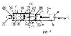
本発明は、全血から血漿を分離するための複部構成装置であって、全血を受け入れるための試料採取ユニット(11;12)と、血漿を抽出するための複数の層を備えた層状フィルタを備えたフィルタユニット(10)と、フィルタユニット(10)内に部分真空を作り出すための、圧送ユニット、好ましくはプランジャポンプ(20)とを備えた、複部構成装置に関する。本発明によれば、フィルタユニット(10)、およびフィルタユニット(10)に向かって延びる円錐状先端部を備えた血漿収集容器(17)は、フィルタカートリッジ(13)内に含まれ、このフィルタカートリッジ(13)は、血漿抽出後に分解され、したがって分析器内への試料投入のために血漿収集容器(17)の円錐状先端部(9)を露出させる。【選択図】図1The present invention is a multi-part component apparatus for separating plasma from whole blood, comprising a sampling unit (11; 12) for receiving whole blood and a plurality of layers for extracting plasma. The invention relates to a multi-part construction device comprising a filter unit (10) with a filter and a pumping unit, preferably a plunger pump (20), for creating a partial vacuum in the filter unit (10). According to the present invention, a filter unit (10) and a plasma collection container (17) with a conical tip extending toward the filter unit (10) are contained within the filter cartridge (13). (13) is degraded after plasma extraction, thus exposing the conical tip (9) of the plasma collection container (17) for sample loading into the analyzer. [Selection] Figure 1
Description
本発明は、全血から血漿を分離するための複部構成装置であって、全血を受け入れるための試料採取ユニットと、血漿を抽出するための複数の層を備えた層状フィルタを備えたフィルタユニットと、フィルタユニット内に部分真空を作り出すための圧送ユニット、好ましくはプランジャポンプとを備えた、複部構成装置に関する。本発明は、さらに、全血から血漿を分離するための複層フィルタユニットを備えたフィルタカートリッジに関する。 The present invention is a multi-part device for separating plasma from whole blood, a filter comprising a sampling unit for receiving whole blood and a layered filter comprising a plurality of layers for extracting plasma The invention relates to a multi-part construction device comprising a unit and a pumping unit, preferably a plunger pump, for creating a partial vacuum in the filter unit. The invention further relates to a filter cartridge comprising a multilayer filter unit for separating plasma from whole blood.
全血から血漿を分離するために主に試験室で使用される遠心分離器以外に、ろ過を用いて全血から血漿を分離することによってポイント・オブ・ケア(PoC)において非常に僅かな量の血漿を得るための装置が、いくつか知られている。 In addition to centrifuges used primarily in laboratories to separate plasma from whole blood, very small quantities at point of care (PoC) by separating plasma from whole blood using filtration Several devices are known for obtaining plasma of these.
最も簡単な場合では、血漿分離は、DE 40 15 589 Al(BOEHRINGER MANNHEIM)に説明されたような複層試験ストリップを用いて行われてよく、この場合、不活性担体層上の輸送層が、試料流体(全血)を投入領域から測定領域に輸送するために設けられる。輸送層は、たとえばガラス繊維マットから作製されてよく、その投入領域内では血漿分離層によって被覆される。しかし、その手順は、分析器処理試験ストリップのみに適する。
In the simplest case, the plasma separation may be performed using a multilayer test strip as described in
欧州特許第0 550 950 A2号(SANWA KAGAKU KENKYUSHO)から、血清および血漿を分離するための方法および装置が知られている。この文献は、血漿抽出のための装置の多様な変形形態を提示し、ここではたとえば、図1から4において、血漿分離装置が血液試料採集装置内に組み込まれる変形形態が説明される。部分真空を用いて、血液は最初に、2層分離フィルタが中に配設された収集容器内に吸引される。血液試料が採取された後、収集容器は真空流体容器に連結され、血漿は、分離フィルタによって分離され、流体容器内に収集される。図5および6に示される変形形態では、血漿分離に必要とされる部分真空は、プランジャ注射器を用いて生成される。図9および10の変形形態は、さらに、これもまた血漿を得るために使用されてよい注射器投入フィルタの種類を示す。 From EP 0 550 950 A2 (SANWA KAGAKA KENKYUSHO) a method and device for separating serum and plasma is known. This document presents various variants of a device for plasma extraction, for example here in FIGS. 1 to 4 a variant in which a plasma separation device is incorporated in a blood sample collection device is described. Using a partial vacuum, blood is first aspirated into a collection container in which a two-layer separation filter is disposed. After the blood sample is collected, the collection container is connected to the vacuum fluid container, and the plasma is separated by a separation filter and collected in the fluid container. In the variation shown in FIGS. 5 and 6, the partial vacuum required for plasma separation is generated using a plunger syringe. The variant of FIGS. 9 and 10 further illustrates the type of syringe input filter that may also be used to obtain plasma.
国際公開第96/24425 A1号(FIRST MEDICAL INC.)から、特にその図1から3および8から、血漿分離のための方法および装置が知られている。「血液分離装置(Blood Separation Device)」と呼ばれる装置は、フィルタ要素と、可撓性管と、その端部に、「血液分離装置」内に導入される針とを備える。可撓性管上に作用するぜん動ポンプを備えるモータユニットを用いて、全血は、「血液分離装置」から吸引され、圧送されてフィルタ要素を通り抜け、それによって血漿は分離され、フィルタユニットの血漿出力開口部において、さらなる使用のために得られ得る。圧力がかけられたときにフィルタユニットにおいて遭遇する比較的高い制御されない圧力値、および全血が連続的に吸い出されるときに収集容器内に発生する部分真空が、欠点である。 A method and apparatus for plasma separation is known from WO 96/24425 A1 (FIRST MEDICAL INC.), In particular from FIGS. 1 to 3 and 8 thereof. A device called a “Blood Separation Device” comprises a filter element, a flexible tube and at its end a needle introduced into the “blood separation device”. Using a motor unit with a peristaltic pump acting on a flexible tube, whole blood is drawn from the “blood separator” and pumped through the filter element, whereby the plasma is separated and the plasma of the filter unit At the output opening may be obtained for further use. Disadvantages are the relatively high uncontrolled pressure values encountered in the filter unit when pressure is applied, and the partial vacuum generated in the collection container when whole blood is continuously drawn.
欧州特許第1 469 068 A1号は、核酸を分離し精製するための装置であって、第1の開口部分が中に形成される前端部分と、液体をその中に保持することができる収容部分とを有する円筒状注射器を備える、装置を開示する。固体相保持部材が、注射器の前端部分に連結され、流れ穴が、固体相保持部材の前端側に形成される。表面上にヒドロキシル基を有する有機ポリマーからなり、試料溶液中の核酸を吸着および脱着することができる固体相が、前記固体相保持部材内に収容される。注射器の前端部内には、固定相要素に向かって断面の直径を増大させる形状の液体誘導表面が形成される。装置は、核酸を分離および精製するために使用され得るが、血漿分離装置としては働かない。 EP 1 469 068 A1 is an apparatus for separating and purifying nucleic acids, a front end part in which a first opening part is formed, and a receiving part which can hold a liquid therein An apparatus is disclosed comprising a cylindrical syringe having: A solid phase holding member is connected to the front end portion of the syringe, and a flow hole is formed on the front end side of the solid phase holding member. A solid phase made of an organic polymer having a hydroxyl group on the surface and capable of adsorbing and desorbing nucleic acids in the sample solution is accommodated in the solid phase holding member. Formed in the front end of the syringe is a liquid guide surface shaped to increase the cross-sectional diameter toward the stationary phase element. The device can be used to separate and purify nucleic acids but does not work as a plasma separation device.
米国特許第6,761,855 B1号からは、生体分子、より詳細にはオリゴヌクレオチドなどの複合化学物質の固体相合成または精製に使用するための改良されたカラムが、知られている。カラムは、流体管または複数の流体管束が、流体をカラム内に効率良く分注することができるのに十分な直径を備えた上部オリフィスを有する。カラムは上側空洞部分を有し、この上側空洞部分は、カラムを吸入するためにピペット先端部として使用することができるように分注ピペットに適合させるように構成されサイズ設定される。カラムは、固体支持体をカラムの中央空洞部分内に含むために下側フリットを配置しやすくするための肩部を備えた下側空洞部分を有する。上側フリットは、中央空洞部分内に好都合に配置されて、固体相樹脂を封止することができる。カラムの下端先端部は、雄型ルアー連結をもたらすようにルアータイプ継手として構成される。上側空洞部分は、別のカラムの雄型ルアーと接面するように構成され、それにより、2つまたは複数のカラムが直列に連結される。 From US Pat. No. 6,761,855 B1 an improved column is known for use in solid phase synthesis or purification of biomolecules, more particularly complex chemicals such as oligonucleotides. The column has an upper orifice with a diameter sufficient for a fluid tube or a plurality of fluid tube bundles to efficiently dispense fluid into the column. The column has an upper cavity portion that is configured and sized to fit a dispensing pipette so that it can be used as a pipette tip to inhale the column. The column has a lower cavity portion with a shoulder to facilitate placement of the lower frit to contain the solid support within the central cavity portion of the column. The upper frit can be conveniently located within the central cavity portion to seal the solid phase resin. The lower end tip of the column is configured as a luer type coupling to provide a male luer connection. The upper cavity portion is configured to interface with a male luer of another column, thereby connecting two or more columns in series.
米国特許第4,0461,45A B1号は、少量投与注射器に大型の保存注射器から充填するために少量投与注射器をその保存注射器に接合するための連結器を示す。連結器は、管状の雌型−雌型結合器を有し、フィルタ要素が装備され得る。したがって、大型の保存注射器内に存在し得る粒子状物質は、少量投与注射器に移送する前にろ過除去される。 U.S. Pat. No. 4,0461,45A B1 shows a connector for joining a small dose syringe to the small dose syringe to fill it from a large storage syringe. The coupler has a tubular female-female coupler and can be equipped with a filter element. Thus, particulate matter that may be present in a large storage syringe is filtered off before being transferred to the small dose syringe.
本発明の目的は、取り扱いが簡単で経済的でなければならない、全血から血漿を分離するための装置を提案することであり、ここでは、その後の施与ステップのための血漿試料が、少量の血液試料からであっても、および/または高いヘマトクリット値を有する試料からであっても得られ、これらの試料は、簡単な方法で分析器の投入ユニットに送られ得る。 The object of the present invention is to propose an apparatus for separating plasma from whole blood, which must be simple and economical to handle, where a plasma sample for a subsequent application step is small. From blood samples and / or from samples with high hematocrit values, these samples can be sent in a simple manner to the input unit of the analyzer.
本発明によれば、この目的は、フィルタユニット、およびフィルタユニットに向かって延びる円錐状先端部を備えた血漿収集容器が、フィルタカートリッジ内に含まれることを提案することによって達成され、このフィルタカートリッジは、血漿抽出後に分離可能であり、または分解されてよく、したがって分析器内への試料投入のために血漿収集容器の円錐状先端部を露出させる。血漿収集容器は、その先端部によって封止部をフィルタユニットに向かって突き刺し、その反対側の端部において、圧送装置、たとえばプランジャポンプに通じる通路を有する支持要素によって、好ましくは、締め付け封止部によって保持される。 According to the present invention, this object is achieved by proposing that a filter unit and a plasma collection container with a conical tip extending towards the filter unit are contained within the filter cartridge. May be separable after plasma extraction or degraded, thus exposing the conical tip of the plasma collection container for sample loading into the analyzer. The plasma collection container is preferably clamped and sealed by a support element having a passage leading to a pumping device, e.g. a plunger pump, at its opposite end, piercing the seal towards the filter unit by its tip. Held by.
フィルタユニットに向かう封止部およびフィルタカートリッジ内の支持要素または締め付け封止部は、死容積部または補償容積部を画定し、この容積部は、空気透過性連結部、たとえば補償開口部または多孔性膜を介して圧送装置に連結される。このようにして、フィルタユニットは、(圧送ユニットのプランジャの取り扱いに応じて)制御されない直接的な方法で圧力にかけられるのではなく、ゆっくりと、均一に強度を減じながらかけられ、この圧力状況は、分離装置の個々の部分の幾何学的形状(たとえば、プランジャポンプの吸引容積部とフィルタカートリッジ内の補償容積部との間の比)、およびフィルタ要素の特性によって決定される。 The seal towards the filter unit and the support element or clamping seal in the filter cartridge define a dead volume or compensation volume, which volume is an air permeable connection, such as a compensation opening or porosity. It is connected to a pumping device through a membrane. In this way, the filter unit is not subjected to pressure in an uncontrolled direct manner (depending on the handling of the plunger of the pumping unit), but slowly and uniformly with reduced strength, this pressure situation being Depending on the geometry of the individual parts of the separating device (eg the ratio between the suction volume of the plunger pump and the compensation volume in the filter cartridge) and the characteristics of the filter element.
好ましくは、フィルタカートリッジは、円錐状先端部を備えた血漿収集容器を含む血漿アプリケータを、フィルタユニットを含むフィルタ筺体から引っ張る、螺脱するまたは捩じり取ることによって分解または分離され得る。血漿を抽出、血漿アプリケータを取り外した後、円錐状先端部を備えた血漿収集容器は、この先端部を用いて、分析器の投入開口部上に直接的に結合され、得られた血漿試料は、その後の分析決定のために分析器内に吸引され得る。 Preferably, the filter cartridge can be disassembled or separated by pulling, unscrewing or twisting off a plasma applicator comprising a plasma collection container with a conical tip from a filter housing containing a filter unit. After extracting the plasma and removing the plasma applicator, the plasma collection container with the conical tip is directly coupled onto the input opening of the analyzer using this tip and the resulting plasma sample Can be aspirated into the analyzer for subsequent analytical decisions.
本発明のさらなる目的は、全血から血漿を抽出するための、複層フィルタユニットを備えたフィルタカートリッジであって、その内部に、封止部をフィルタユニット方向に突き刺す円錐状の先端部を備えた血漿収集容器を有する、フィルタカートリッジであり、ここでは、血漿収集容器は、締め付け封止部によってその反対側においてフィルタカートリッジ内に保持される。フィルタカートリッジは、注射器またはいわゆるMonovette内に配設され、または組み込まれもしくは設定され得る。 A further object of the present invention is a filter cartridge having a multilayer filter unit for extracting plasma from whole blood, and having a conical tip portion that pierces the sealing portion in the direction of the filter unit. A filter cartridge having a plasma collection container, wherein the plasma collection container is held in the filter cartridge on the opposite side by a clamping seal. The filter cartridge can be disposed in, incorporated in or set in a syringe or so-called Monovette.
本発明は、次に、添付の図を参照してさらに説明される。 The invention will now be further described with reference to the accompanying figures.
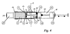
すべての変形形態は、共通要素としてのフィルタカートリッジ13を、試料採取ユニットの一体的構成要素として(図1または3の注射器11を参照)、または試料採取ユニット内にユーザによって挿入される別個の部分として(図4から7のMonovette 12を参照)有する。フィルタカートリッジ13は、複層状フィルタを備えたフィルタユニット10と、フィルタユニット10に向かって延びる円錐状先端部(血漿先端部)を備えた血漿収集容器17とを備える。フィルタカートリッジ13は、血漿抽出後に平面εに沿って分離または破断されて、血漿収集容器17を含む血漿アプリケータ14と、フィルタユニット10を含むフィルタ筺体8とを生み出す。
All variants have the
図1から3に示される第1の変形形態は、フィルタ筺体8上に形成されたルアーコーン22を備えた注射器11内に組み込まれたフィルタカートリッジ13を有し、ルアーコーン22上には、針が、全血試料を採取するために突き立てられ得る。注射器11の筺体内では、棒を用いて初期位置から破線によって示される最終位置まで手動で移動され得るプランジャ18が、そのプランジャ筺体20内に配設され、フィルタユニット10、およびフィルタユニット10に向かって延びる円錐先端部を備えた血漿収集容器17は、フィルタカートリッジの必須部分として提供される。摺動可能なプランジャ18を備えたプランジャ筺体20は、血漿分離に必要とされる部分真空を作り出すための圧送装置としての役割を果たす。
The first variant shown in FIGS. 1 to 3 has a
装置の起動時、全血試料41は、プランジャ18を後方に引っ張ることによってフィルタユニット10内に吸引され、それによって血漿前部または血漿画分40が生成され、この血漿前部または血漿画分は、深層フィルタ3と、固体血液成分(主に赤血球、RBC)の完全な除去のための小孔停止膜4と、横方向格子5とからなる複層状フィルタを通って血漿収集容器17の先端部9内に移動する。
Upon activation of the device, the
血漿収集容器17は、先端部9で封止部15をフィルタユニット10に向かって突き刺し、反対側の開放端部上では、圧送装置(プランジャ部分20)に向かう通路を有する、支持要素、好ましくは締め付け封止部27によって保持され封止される。圧送装置に向かうこの通路内には、疎水性の空気透過性要素16(液体停止部)が設けられる。これは、分離された血漿が、先端部9の反対側の通路から流出することを防止する。
The
フィルタユニット10に向かう封止部15およびプランジャ筺体20に向かう締め付け封止部27は、フィルタカートリッジ13内に補償容積部21を画定し、この補償容積部は、空気透過性通路、たとえば締め付け封止部27内の補償開口部25または多孔膜を介して注射器11の圧送装置に連結される。
The sealing
図1から3による装置の第1の変形形態では、血漿抽出は、以下の通りに実施され得る。
− 組み込まれたフィルタカートリッジ13を備えた注射器11を滅菌梱包品から取り出す。
− 針をルアーコーン22上に付ける。
− 選択された血管を針で穿孔する。
− プランジャ18を停止部に突き当たるまで後方に引っ張ることによって血液試料を吸引する。
− プランジャ棒を係止位置24に係止する。
In a first variant of the device according to FIGS. 1 to 3, plasma extraction can be performed as follows.
-Remove the syringe 11 with the
-Place the needle on the
-Perforating selected blood vessels with a needle.
-Aspirate the blood sample by pulling the
-Lock the plunger rod in the
(任意選択:プランジャ棒は、内部の流れ方向の逆転または圧力変動、および高いヘマトクリット値および/または少量試料において得られた血漿の結果生じるあらゆる汚染を回避するために折り取られてよい。)
フィルタユニット10の深層フィルタ3は、たとえば、0.5μmから10μm、より良好には1μmから5μm、好ましくは3μm未満の保持範囲を有する、結合剤を有さないガラス繊維(通常、Whatman Inc.製のFV−2、それぞれBohringer−MannheimのDE 40 15 589 A1または欧州特許第0 239 002 A1 号)から構築され得る。赤血球(RBC)は、深層フィルタ3の薄いガラス繊維上に、破裂する、または流量に過度な影響を与えることなく収集される。
(Optional: The plunger rod may be folded to avoid reversal of internal flow direction or pressure fluctuations, and any contamination resulting from high hematocrit values and / or plasma obtained in small samples.)
The depth filter 3 of the
− フィルタユニット10の断面およびヘマトクリットに応じて、「血漿前部」または「血漿画分」40が形成されることになり、これは、妨げられることなく停止膜4を通過することができる。深層フィルタによって阻止されない残留RBCは、停止膜4によってろ過除去される。この目的のために、停止膜4は、深層フィルタ3のものよりかなり小さい孔サイズ、すなわち、400nm未満、好ましくは200nm未満の孔直径を有する。その孔サイズのために血球の大部分をすでに保持するが、血漿画分の流れは妨げない深層フィルタ3と、これより小さい孔サイズにより、残りの血球を確実に保持するが、先行する深層フィルタ4が存在しなかった場合はその孔の数が限定されるためにすぐに詰まると考えられる、後続の停止膜4とを組み合わせることにより、フィルタを詰まらすことなく血球を確実に分離することが達成され、それによって十分に大量の血漿試料を得ることを可能にすることができる。
Depending on the cross-section and hematocrit of the
− フィルタユニット10内に確立された、せいぜい500mbar、より良好には300mbar、理想的には100から150mbarの部分真空は、フィルタユニット10の幾何学的形状(補償容積部21とプランジャ筺体20の吸引容積部23との比)と一緒になって、流量、したがってフィルタユニット10の停止膜4内の特にRBC上に作用するせん断力を決定する。RBCの破裂(血球破壊)は、補償容積部21を最適化することによって効率的に防止され得る。
A partial vacuum established in the
− フィルタユニット10の横方向格子5は、停止膜4が緊密に「封止する」ことを効率的に防止することによって、血漿が収集され、停止膜4の後方に血漿収集容器17に向かって吸い出されることを可能にする。この格子構造により、一方では横方向格子5は、停止膜4の非連続的支持体として作用して、血漿を停止膜4の出力側に流出させる。溝を形成することにより、格子構造は、さらに、停止膜4の領域の上で退出する血漿が、血漿収集容器17に向かって集まることを可能にする。
-The
(横方向格子5のこの機能は、代替的に、停止膜に面する封止部15の側を構造化することによって、たとえば、打ち抜き、または別の形でその表面の十分な粗さを設けることによってもたらされてよい。)
− 血液抽出はまた、以下によって、すなわち
− 停止膜4が、血液の粒子状成分によって詰まらされたとき、または
− 特に40%未満のヘマトクリット値の場合、疎水性の空気透過性要素16によって境界付けられた血漿収集容器17の管腔が、血漿によって完全に充填されたときにさらなる血漿抽出を終結する、血漿収集容器17の端部にある、または締め付け封止部27の通路内の疎水性の空気透過性要素16(液体停止部)によって終了する。
(This function of the
-Blood extraction is also bounded by a hydrophobic air-
− 任意選択により、血漿収集容器17上のマークを用いて、血漿の所望の量が得られていることが目視検査によって確認され得る。
− 注射器11のフィルタ筺体8(図2の矢印26を参照)は、プランジャ部分20から回して外され、または捩じり取られ、したがって、フィルタカートリッジ13は、平面εに沿って、フィルタユニット10を含む第1の部分と、円錐状先端部を備えた血漿収集容器17を含む血漿アプリケータ部分14とに分割され、血漿収集容器17の先端部9は、したがって露出される(図3)。
-Optionally, the mark on the
The
示される変形形態では、より小さい封止表面を備えた血漿収集容器17の封止部15と比較して、締め付け封止部27の固有の高い静的摩擦は、筺体のさらなる回転または引っ張りによる筺体壁内の通気溝19の露出前に、血漿収集容器17の先端部9を安全に結合解除することを確実にし、この溝は、部分的に多孔性の締め付け封止部27によるおよび/または補償開口部25による、プランジャ筺体20内の吸引容積部23と補償容積部21との間のすばやい圧力補償を可能にする。
In the variant shown, the inherent high static friction of the clamping
早期の結合解除はまた、予想されない面倒な問題および汚染が、分離手順中に血漿収集容器17の先端部9において起こらないことも確実にする。
血漿収集容器17の端部にある締め付け封止部27内の液体停止部16はまた、吸引容積部23と補償容積部21の間の圧力補償が遅延した場合、先端部9の地点における領域内の血漿試料の分画化も防止する。
Early decoupling also ensures that unexpected troublesome problems and contamination do not occur at the
The
(代替的には、血漿収集容器17の先端部9は、ルアーコーンとして設計されてよい)。
− 得られた血漿によって少なくとも部分的に充填された血漿収集容器17(およびハンドルとして作用するプランジャ筺体20)を、ここではこれ以上示されない分析器の投入開口部上に結合させる。
(Alternatively, the
A plasma collection container 17 (and a
− 血漿試料を、分析器の投入開口部上に結合された血漿収集容器17から、分析器手段によって吸引することによって分析器に入れる。補償開口部25または代替的には締め付け封止部27の多孔領域は、血漿収集容器17の完全な排出を可能にする。
A plasma sample is placed in the analyzer by aspiration by means of the analyzer from a
− 本発明によって得られた血漿試料内に含まれた物質を、たとえばヘモグロビン値などを分析器内で分析的に決定する。
図4から7による装置の第2の変形形態では、血漿抽出は、以下の通りに実施され得る。
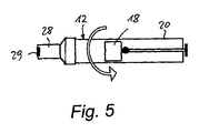
− 図5のようなMonovette 12を滅菌梱包品から取り出す。
− 穿孔膜29を備えたアダプタキャップ28をプランジャ筺体20から回して外す。
− フィルタカートリッジ13を、図4によって、アダプタキャップ28とプランジャ筺体20の間に配置する。
− 以下によって、すなわち
− プランジャ18をこれが停止部に当たるまで後方に引っ張ることによって
− プランジャ棒を、破線で示される係止位置24に係止することによって
Monovette 12内に部分真空を作り出す。
(任意選択:内部流れ方向の逆転を回避するためにプランジャ棒を折り取る)
− アダプタキャップ28の穿孔膜29を穿孔針、たとえば翼状針上に結合させる。
− Monovette 12内に広く行きわたった部分真空を用いて血液試料を吸引する。
The substance contained in the plasma sample obtained according to the invention is determined analytically, for example, in the analyzer, such as hemoglobin value.
In a second variant of the device according to FIGS. 4 to 7, plasma extraction can be performed as follows.
-Remove
-Unscrew the
The
By creating a partial vacuum in the
(Optional: Fold down plunger rod to avoid reversal of internal flow direction)
The piercing
Aspirate the blood sample using a partial vacuum that has spread widely within the
フィルタユニット10の深層フィルタ3は、たとえば、0.5μmから10μm、より良好には1μmから5μm、好ましくは3μm未満の保持範囲を有する、結合剤を有さないガラス繊維(通常、Whatman Inc.製のFV−2、それぞれBohringer−MannheimのDE 40 15 589 A1または欧州特許第0 239 002 A1 号)から構築され得る。赤血球(RBC)は、深層フィルタ3の薄いガラス繊維上に、破裂する、または流れの速度に過度な影響を与えることなく収集される。
The depth filter 3 of the
− フィルタユニット10の断面およびヘマトクリットに応じて、「血漿前部」または「血漿画分」40が形成されることになり、これは、妨げられることなく停止膜4を通過することができる。深層フィルタによって阻止されない残留RBCは、停止膜4によってろ過除去される(図4)。この目的のために、停止膜4は、深層フィルタ3のものよりかなり小さい孔サイズ、すなわち、400nm未満、好ましくは200nm未満の孔直径を有する。その孔サイズのために血球の大部分をすでに保持するが、血漿画分の流れを妨げない深層フィルタ3と、これより小さい孔サイズにより、残りの血球を確実に保持するが、先行する深層フィルタ4が存在しなかった場合はその孔の数が限定されるためにすぐに詰まると考えられる、後続の停止膜4とを組み合わせることにより、フィルタを詰まらすことなく血球を確実に分離することが達成され、それによって十分に大量の血漿試料を得ることを可能にすることができる。
Depending on the cross-section and hematocrit of the
− フィルタユニット10内に確立された、せいぜい500mbar、より良好には300mbar、理想的には100から150mbarの部分真空は、フィルタユニット10の幾何学的形状(補償容積部21とプランジャ筺体20の吸引容積部23との比)と一緒になって、流量、したがってフィルタユニット10の停止膜4内の特にRBC上に作用するせん断力を決定する。RBCの破裂(血球破壊)は、補償容積部21を最適化することによって効率的に防止され得る。
A partial vacuum established in the
− フィルタユニット10の横方向格子5は、停止膜4が緊密に「封止する」ことを効率的に防止することによって、血漿が収集され、停止膜4の後方に血漿収集容器17に向かって吸い出されることを可能にする(注射器の変形形態も参照)。
-The
(代替策として、横方向格子5のこの機能は、停止膜に面する封止部15の側を構造化することによって、たとえば、打ち抜き、または別の形でその表面の十分な粗さを設けることによってもたらされてよい。)
− 血液抽出は、これもまた以下によって、すなわち
− 停止膜4が、血液の粒子状成分によって詰まらされたとき、または
− 特に40%未満のヘマトクリット値の場合、疎水性の空気透過性要素16によって境界付けられた血漿収集容器17の管腔が、血漿によって完全に充填されたときにさらなる血漿抽出を終結する、血漿収集容器17の端部にある、または締め付け封止部27の通路内の疎水性の空気透過性要素16(液体停止部)によって終了する。
− ここでも、血漿収集容器17上のマークを用いて、血漿の所望の量が得られていることが目視検査によって確認され得る。
(Alternatively, this function of the
-Blood extraction is also by means of a hydrophobic air-
Again, using the marks on the
− Monovette 12の前部分は、プランジャ部分20から回して外されまたは捩じり取られ、したがって、間置されたフィルタカートリッジ13は、平面εに沿って、フィルタユニット10を含むフィルタ筺体8と、円錐状先端部を備えた血漿収集容器17を含む血漿アプリケータ部分14とに分割され、血漿収集容器17の先端部9は、したがって露出される(図7)。血漿アプリケータ14は、取り扱いを容易にするためにフィルタ筺体20に連結されたままである。これらの部分が分離された後、装置は図3に対応する。
The front part of the
手順のさらなるステップは、本発明による装置の第1の変形形態に説明されたものに対応する。 The further steps of the procedure correspond to those described in the first variant of the device according to the invention.
Claims (11)
全血を受け入れるための試料採取ユニット(11;12)と、
血漿を抽出するための複数の層を備えた層状フィルタを備えたフィルタユニット(10)と、
部分真空を前記フィルタユニット(10)内に作り出すための、圧送ユニット、好ましくはプランジャポンプ(20)とを備える、複部構成装置において、
前記フィルタユニット(10)、および前記フィルタユニット(10)に向かって延びる円錐状先端部を有する血漿収集容器(17)が、フィルタカートリッジ(13)内に含まれ、
前記血漿収集容器(17)の前記円錐状先端部(9)が、封止部(15)を前記フィルタユニット(10)に向かって突き刺し、前記収集容器(17)は、その反対側の端部において、前記圧送装置に通じる通路を有する支持要素、好ましくは締め付け封止部(27)によって保持され、
前記フィルタカートリッジ(13)が、血漿抽出後に分離可能であり、したがって分析器内への試料投入のために前記血漿収集容器(17)の前記円錐状先端部(9)を露出させることを特徴とする、複部構成装置。 A multi-component device for separating plasma from whole blood,
A sampling unit (11; 12) for receiving whole blood;
A filter unit (10) comprising a layered filter comprising a plurality of layers for extracting plasma;
In a multi-part construction device comprising a pumping unit, preferably a plunger pump (20), for creating a partial vacuum in the filter unit (10),
Contained within the filter cartridge (13) is a plasma collection container (17) having a filter unit (10) and a conical tip extending toward the filter unit (10),
The conical tip (9) of the plasma collection container (17) pierces the sealing part (15) toward the filter unit (10), and the collection container (17) has an opposite end. In a support element having a passage leading to the pumping device, preferably a clamping seal (27),
The filter cartridge (13) is separable after plasma extraction and thus exposes the conical tip (9) of the plasma collection container (17) for sample loading into the analyzer A multi-part configuration device.
Applications Claiming Priority (3)
| Application Number | Priority Date | Filing Date | Title |
|---|---|---|---|
| EP12179900.1A EP2695655A1 (en) | 2012-08-09 | 2012-08-09 | Multi-part device for extracting plasma from blood |
| EP12179900.1 | 2012-08-09 | ||
| PCT/EP2013/066539 WO2014023761A1 (en) | 2012-08-09 | 2013-08-07 | Multi-part device for extracting plasma from blood |
Publications (2)
| Publication Number | Publication Date |
|---|---|
| JP2015527582A true JP2015527582A (en) | 2015-09-17 |
| JP2015527582A5 JP2015527582A5 (en) | 2016-09-23 |
Family
ID=46851288
Family Applications (1)
| Application Number | Title | Priority Date | Filing Date |
|---|---|---|---|
| JP2015525876A Pending JP2015527582A (en) | 2012-08-09 | 2013-08-07 | Multi-part component device for extracting plasma from blood |
Country Status (6)
| Country | Link |
|---|---|
| US (1) | US9283313B2 (en) |
| EP (2) | EP2695655A1 (en) |
| JP (1) | JP2015527582A (en) |
| CN (1) | CN104519976B (en) |
| HK (1) | HK1206301A1 (en) |
| WO (1) | WO2014023761A1 (en) |
Families Citing this family (20)
| Publication number | Priority date | Publication date | Assignee | Title |
|---|---|---|---|---|
| US9657290B2 (en) | 2012-07-03 | 2017-05-23 | The Board Of Trustees Of The Leland Stanford Junior University | Scalable bio-element analysis |
| WO2015006515A1 (en) | 2013-07-09 | 2015-01-15 | Sri International | Biomarker panel for dose assessment of radiation injury and micro plasma filter |
| WO2016073415A2 (en) | 2014-11-04 | 2016-05-12 | Wainamics, Inc. | Microscale plasma separator |
| WO2017027342A1 (en) | 2015-08-07 | 2017-02-16 | Schlumberger Technology Corporation | Method of performing complex fracture operations at a wellsite having ledged fractures |
| WO2017027433A1 (en) | 2015-08-07 | 2017-02-16 | Schlumberger Technology Corporation | Method of performing integrated fracture and reservoir operations for multiple wellbores at a wellsite |
| WO2017027340A1 (en) | 2015-08-07 | 2017-02-16 | Schlumberger Technology Corporation | Method integrating fracture and reservoir operations into geomechanical operations of a wellsite |
| US11578568B2 (en) | 2015-08-07 | 2023-02-14 | Schlumberger Technology Corporation | Well management on cloud computing system |
| US10578606B2 (en) | 2015-09-01 | 2020-03-03 | Becton, Dickinson And Company | Depth filtration device for separating specimen phases |
| EP3165921A1 (en) * | 2015-11-05 | 2017-05-10 | Dominik Olbrzymek | A kit for centrifugal separation of biological fluid components and a method for centrifugal separation of biological fluid components |
| CN105445083B (en) * | 2015-12-21 | 2018-09-11 | 丹娜(天津)生物科技有限公司 | Exempt to centrifuge whole blood processing module |
| CN115254210A (en) | 2016-11-14 | 2022-11-01 | 浩康生物系统公司 | Method and apparatus for sorting target particles |
| CN110891623B (en) * | 2017-07-17 | 2022-08-26 | 波士顿科学国际有限公司 | Cryotherapy delivery device |
| CN109806657A (en) * | 2017-11-20 | 2019-05-28 | 李泉 | A kind of blood plasma extraction element |
| CN108577896A (en) * | 2018-03-20 | 2018-09-28 | 四川大学华西第二医院 | Specimen collecting bottle |
| WO2019236822A1 (en) | 2018-06-07 | 2019-12-12 | Becton, Dickinson And Company | Biological fluid separation device |
| GB201819417D0 (en) * | 2018-11-29 | 2019-01-16 | Quantumdx Group Ltd | Vacuum-assisted drying of filters in microfluidic systems |
| FR3093651A1 (en) * | 2019-03-15 | 2020-09-18 | Seigniory Chemical Products Ltd. - Produits Chimiques Seigneurie Ltee | SYSTEM AND METHOD FOR FILTERING SAMPLES FROM CONTAINERS |
| US10518260B1 (en) | 2019-05-01 | 2019-12-31 | Nano Discovery, Inc. | Device for separation of plasma or serum from blood cells and methods of using the device |
| US11439768B2 (en) * | 2019-07-17 | 2022-09-13 | Wagner Florexil | Compartmentalized syringe for combined medicine and flush solution |
| CN111141569B (en) * | 2020-01-22 | 2020-12-29 | 兰州大学 | Hydrops class pathological analysis sediment layer extraction element |
Citations (5)
| Publication number | Priority date | Publication date | Assignee | Title |
|---|---|---|---|---|
| US4021352A (en) * | 1974-03-30 | 1977-05-03 | Walter Sarstedt Kunststoff-Spritzgusswerk | Filter device for separating blood fractions |
| US5139685A (en) * | 1991-03-26 | 1992-08-18 | Gds Technology, Inc. | Blood separation filter assembly and method |
| JPH0593721A (en) * | 1990-12-03 | 1993-04-16 | Sanwa Kagaku Kenkyusho Co Ltd | Serum/plasma separating apparatus |
| JPH09196911A (en) * | 1996-01-19 | 1997-07-31 | Fuji Photo Film Co Ltd | Blood filter unit |
| JP2007003479A (en) * | 2005-06-27 | 2007-01-11 | Sekisui Chem Co Ltd | Blood separation device |
Family Cites Families (29)
| Publication number | Priority date | Publication date | Assignee | Title |
|---|---|---|---|---|
| US3814079A (en) * | 1972-04-28 | 1974-06-04 | Upjohn Co | Liquid collecting and filtering device |
| DE2415618C3 (en) * | 1974-03-30 | 1978-06-22 | Walter Sarstedt Kunststoff-Spritzgusswerk, 5223 Nuembrecht | Filter device for separating blood fractions |
| US4046145A (en) * | 1976-06-29 | 1977-09-06 | American Hospital Supply Corporation | Syringe connector |
| US4131549A (en) | 1977-05-16 | 1978-12-26 | Ferrara Louis T | Serum separation device |
| DE3610429A1 (en) | 1986-03-27 | 1987-10-01 | Boehringer Mannheim Gmbh | Coagulation-neutral, hydrophilic glass fibers |
| US4921618A (en) | 1987-07-01 | 1990-05-01 | Basf Corporation | Inverted separation and transfer device, and process for using same |
| US4990253A (en) | 1988-01-25 | 1991-02-05 | Abbott Laboratories | Fluid sample filtration device |
| CA2006880A1 (en) * | 1989-01-03 | 1990-07-03 | William D. Huse | Push column and chromatography method |
| DE3913197A1 (en) * | 1989-04-21 | 1990-10-25 | Sarstedt Walter Geraete | BLOOD COLLECTION DEVICE |
| DE4015589A1 (en) | 1990-05-15 | 1991-11-21 | Boehringer Mannheim Gmbh | DEVICE AND THE USE THEREOF FOR SEPARATING PLASMA FROM WHOLE BLOOD |
| US5234608A (en) | 1990-12-11 | 1993-08-10 | Baxter International Inc. | Systems and methods for processing cellular rich suspensions |
| US5672481A (en) | 1991-10-23 | 1997-09-30 | Cellpro, Incorporated | Apparatus and method for particle separation in a closed field |
| JPH05188053A (en) | 1992-01-10 | 1993-07-27 | Sanwa Kagaku Kenkyusho Co Ltd | Instrument for separating serum or plasma component from blood |
| US5578459A (en) * | 1993-11-24 | 1996-11-26 | Abbott Laboratories | Method and apparatus for collecting a cell sample from a liquid specimen |
| GB9426251D0 (en) * | 1994-12-24 | 1995-02-22 | Fsm Technologies Ltd | Device |
| WO1996024425A1 (en) | 1995-02-09 | 1996-08-15 | First Medical, Inc. | Peristaltic system and method for plasma separation |
| US5637087A (en) * | 1995-03-22 | 1997-06-10 | Abbott Laboratories | Prefilled, two-constituent syringe |
| US6117394A (en) * | 1996-04-10 | 2000-09-12 | Smith; James C. | Membrane filtered pipette tip |
| US6669905B1 (en) * | 1998-05-21 | 2003-12-30 | Baxter International Inc. | Systems and methods for collecting plasma that is free or virtually free of cellular blood species |
| CA2405443A1 (en) * | 2000-03-31 | 2001-10-11 | Baxter International, Inc. | Systems and methods for collecting leukocyte-reduced blood components, including plasma that is free or virtually free of cellular blood species |
| US6817256B2 (en) * | 2001-02-27 | 2004-11-16 | Alfa Wassermann, Inc. | Pipette sampling system |
| US6869405B2 (en) * | 2001-03-30 | 2005-03-22 | Becton, Dickinson And Company | Blunt cannula and filter assembly and method of use with point-of-care testing cartridge |
| US6761855B1 (en) * | 2001-11-05 | 2004-07-13 | Biosearch Technologies, Inc. | Column for solid phase processing |
| US7682818B2 (en) * | 2003-03-28 | 2010-03-23 | Fujifilm Corporation | Apparatus for separating and purifying nucleic acid and method for separating and purifying nucleic acid |
| DE102004056655B4 (en) * | 2004-11-23 | 2007-03-29 | Sarstedt Ag & Co. | Sample tubes for receiving body fluid, in particular blood |
| US20100093551A1 (en) * | 2008-10-09 | 2010-04-15 | Decision Biomarkers, Inc. | Liquid Transfer and Filter System |
| EP2264453B1 (en) * | 2009-06-17 | 2013-04-03 | Leukocare Ag | Method for filtering blood |
| ES2410479T3 (en) | 2009-09-17 | 2013-07-02 | F.Hoffmann-La Roche Ag | Device for introducing liquid samples (clot traps) |
| EP2637788A1 (en) | 2010-11-10 | 2013-09-18 | Boehringer Ingelheim Microparts GmbH | Device for filtering blood |
-
2012
- 2012-08-09 EP EP12179900.1A patent/EP2695655A1/en not_active Withdrawn
-
2013
- 2013-08-07 WO PCT/EP2013/066539 patent/WO2014023761A1/en active Application Filing
- 2013-08-07 EP EP13745674.5A patent/EP2882511A1/en not_active Withdrawn
- 2013-08-07 CN CN201380042324.5A patent/CN104519976B/en not_active Expired - Fee Related
- 2013-08-07 JP JP2015525876A patent/JP2015527582A/en active Pending
-
2015
- 2015-02-06 US US14/615,743 patent/US9283313B2/en not_active Expired - Fee Related
- 2015-07-21 HK HK15106907.2A patent/HK1206301A1/en not_active IP Right Cessation
Patent Citations (5)
| Publication number | Priority date | Publication date | Assignee | Title |
|---|---|---|---|---|
| US4021352A (en) * | 1974-03-30 | 1977-05-03 | Walter Sarstedt Kunststoff-Spritzgusswerk | Filter device for separating blood fractions |
| JPH0593721A (en) * | 1990-12-03 | 1993-04-16 | Sanwa Kagaku Kenkyusho Co Ltd | Serum/plasma separating apparatus |
| US5139685A (en) * | 1991-03-26 | 1992-08-18 | Gds Technology, Inc. | Blood separation filter assembly and method |
| JPH09196911A (en) * | 1996-01-19 | 1997-07-31 | Fuji Photo Film Co Ltd | Blood filter unit |
| JP2007003479A (en) * | 2005-06-27 | 2007-01-11 | Sekisui Chem Co Ltd | Blood separation device |
Also Published As
| Publication number | Publication date |
|---|---|
| EP2695655A1 (en) | 2014-02-12 |
| US9283313B2 (en) | 2016-03-15 |
| EP2882511A1 (en) | 2015-06-17 |
| WO2014023761A1 (en) | 2014-02-13 |
| CN104519976A (en) | 2015-04-15 |
| CN104519976B (en) | 2017-03-01 |
| HK1206301A1 (en) | 2016-01-08 |
| US20150151035A1 (en) | 2015-06-04 |
Similar Documents
| Publication | Publication Date | Title |
|---|---|---|
| JP2015527582A (en) | Multi-part component device for extracting plasma from blood | |
| US9808568B2 (en) | Apparatus and method for separating and concentrating a component of a fluid | |
| JP7500671B2 (en) | Biological Fluid Separation Device | |
| DK169311B1 (en) | Apparatus and method for membrane separation of the components of a liquid sample | |
| EP2882512B1 (en) | Method and separation device for separating a filtrate from a sample fluid | |
| EP3085307B1 (en) | Biological fluid collection device | |
| EP2264453B1 (en) | Method for filtering blood | |
| JP2015530566A (en) | Plasma separation system and method for plasma separation | |
| US20020143298A1 (en) | Blunt cannula and filter assembly and method of use with point-of-care testing cartridge | |
| EP2260300B1 (en) | Method and device for particle removal and droplet preparation for qualitative and quantitative bioanalysis | |
| JP2013542445A (en) | Blood filtration equipment | |
| CA2956710A1 (en) | Vacuum-assisted plasma separation | |
| US11305236B2 (en) | Surface tension driven filtration | |
| JP2008279195A (en) | Blood separation filter device | |
| JP4391761B2 (en) | Blood test container | |
| JP2001324501A (en) | Blood plasma or blood serum gathering device | |
| JP2001321369A (en) | Plasma taking tool |
Legal Events
| Date | Code | Title | Description |
|---|---|---|---|
| A521 | Request for written amendment filed |
Free format text: JAPANESE INTERMEDIATE CODE: A523 Effective date: 20160804 |
|
| A621 | Written request for application examination |
Free format text: JAPANESE INTERMEDIATE CODE: A621 Effective date: 20160804 |
|
| A977 | Report on retrieval |
Free format text: JAPANESE INTERMEDIATE CODE: A971007 Effective date: 20170713 |
|
| A131 | Notification of reasons for refusal |
Free format text: JAPANESE INTERMEDIATE CODE: A131 Effective date: 20170803 |
|
| A601 | Written request for extension of time |
Free format text: JAPANESE INTERMEDIATE CODE: A601 Effective date: 20171031 |
|
| A02 | Decision of refusal |
Free format text: JAPANESE INTERMEDIATE CODE: A02 Effective date: 20180328 |