JP2015522433A - Cutting insert and tool with non-slip components - Google Patents
Cutting insert and tool with non-slip components Download PDFInfo
- Publication number
- JP2015522433A JP2015522433A JP2015515645A JP2015515645A JP2015522433A JP 2015522433 A JP2015522433 A JP 2015522433A JP 2015515645 A JP2015515645 A JP 2015515645A JP 2015515645 A JP2015515645 A JP 2015515645A JP 2015522433 A JP2015522433 A JP 2015522433A
- Authority
- JP
- Japan
- Prior art keywords
- insert
- tool
- cutting
- base surface
- cutting insert
- Prior art date
- Legal status (The legal status is an assumption and is not a legal conclusion. Google has not performed a legal analysis and makes no representation as to the accuracy of the status listed.)
- Pending
Links
- 238000005520 cutting process Methods 0.000 title claims abstract description 247
- 230000002093 peripheral effect Effects 0.000 claims description 49
- 238000000034 method Methods 0.000 claims description 14
- 230000001154 acute effect Effects 0.000 claims description 7
- 238000003825 pressing Methods 0.000 claims description 2
- 238000013459 approach Methods 0.000 description 3
- 230000009286 beneficial effect Effects 0.000 description 3
- 238000006073 displacement reaction Methods 0.000 description 2
- 238000003754 machining Methods 0.000 description 2
- 239000000463 material Substances 0.000 description 2
- 238000003801 milling Methods 0.000 description 2
- 229910052782 aluminium Inorganic materials 0.000 description 1
- XAGFODPZIPBFFR-UHFFFAOYSA-N aluminium Chemical compound [Al] XAGFODPZIPBFFR-UHFFFAOYSA-N 0.000 description 1
- 238000005452 bending Methods 0.000 description 1
- 230000001687 destabilization Effects 0.000 description 1
- 229910052751 metal Inorganic materials 0.000 description 1
- 239000002184 metal Substances 0.000 description 1
- 150000002739 metals Chemical class 0.000 description 1
- 238000012986 modification Methods 0.000 description 1
- 230000004048 modification Effects 0.000 description 1
Images


Classifications
-
- B—PERFORMING OPERATIONS; TRANSPORTING
- B23—MACHINE TOOLS; METAL-WORKING NOT OTHERWISE PROVIDED FOR
- B23C—MILLING
- B23C5/00—Milling-cutters
- B23C5/16—Milling-cutters characterised by physical features other than shape
- B23C5/20—Milling-cutters characterised by physical features other than shape with removable cutter bits or teeth or cutting inserts
- B23C5/22—Securing arrangements for bits or teeth or cutting inserts
- B23C5/2204—Securing arrangements for bits or teeth or cutting inserts with cutting inserts clamped against the walls of the recess in the cutter body by a clamping member acting upon the wall of a hole in the insert
- B23C5/2208—Securing arrangements for bits or teeth or cutting inserts with cutting inserts clamped against the walls of the recess in the cutter body by a clamping member acting upon the wall of a hole in the insert for plate-like cutting inserts
- B23C5/2213—Securing arrangements for bits or teeth or cutting inserts with cutting inserts clamped against the walls of the recess in the cutter body by a clamping member acting upon the wall of a hole in the insert for plate-like cutting inserts having a special shape
-
- B—PERFORMING OPERATIONS; TRANSPORTING
- B23—MACHINE TOOLS; METAL-WORKING NOT OTHERWISE PROVIDED FOR
- B23C—MILLING
- B23C5/00—Milling-cutters
- B23C5/16—Milling-cutters characterised by physical features other than shape
- B23C5/20—Milling-cutters characterised by physical features other than shape with removable cutter bits or teeth or cutting inserts
- B23C5/22—Securing arrangements for bits or teeth or cutting inserts
- B23C5/2265—Securing arrangements for bits or teeth or cutting inserts by means of a wedge
- B23C5/2269—Securing arrangements for bits or teeth or cutting inserts by means of a wedge for plate-like cutting inserts
-
- B—PERFORMING OPERATIONS; TRANSPORTING
- B23—MACHINE TOOLS; METAL-WORKING NOT OTHERWISE PROVIDED FOR
- B23B—TURNING; BORING
- B23B2200/00—Details of cutting inserts
- B23B2200/16—Supporting or bottom surfaces
- B23B2200/161—Supporting or bottom surfaces with projections
-
- B—PERFORMING OPERATIONS; TRANSPORTING
- B23—MACHINE TOOLS; METAL-WORKING NOT OTHERWISE PROVIDED FOR
- B23C—MILLING
- B23C2200/00—Details of milling cutting inserts
- B23C2200/16—Supporting or bottom surfaces
- B23C2200/161—Supporting or bottom surfaces with projections
-
- B—PERFORMING OPERATIONS; TRANSPORTING
- B23—MACHINE TOOLS; METAL-WORKING NOT OTHERWISE PROVIDED FOR
- B23C—MILLING
- B23C2210/00—Details of milling cutters
- B23C2210/16—Fixation of inserts or cutting bits in the tool
- B23C2210/168—Seats for cutting inserts, supports for replacable cutting bits
-
- B—PERFORMING OPERATIONS; TRANSPORTING
- B23—MACHINE TOOLS; METAL-WORKING NOT OTHERWISE PROVIDED FOR
- B23C—MILLING
- B23C2270/00—Details of milling machines, milling processes or milling tools not otherwise provided for
- B23C2270/08—Clamping mechanisms or provision for clamping
-
- B—PERFORMING OPERATIONS; TRANSPORTING
- B23—MACHINE TOOLS; METAL-WORKING NOT OTHERWISE PROVIDED FOR
- B23C—MILLING
- B23C5/00—Milling-cutters
- B23C5/16—Milling-cutters characterised by physical features other than shape
- B23C5/20—Milling-cutters characterised by physical features other than shape with removable cutter bits or teeth or cutting inserts
- B23C5/22—Securing arrangements for bits or teeth or cutting inserts
- B23C5/24—Securing arrangements for bits or teeth or cutting inserts adjustable
- B23C5/2465—Securing arrangements for bits or teeth or cutting inserts adjustable the adjusting means being notches
-
- B—PERFORMING OPERATIONS; TRANSPORTING
- B23—MACHINE TOOLS; METAL-WORKING NOT OTHERWISE PROVIDED FOR
- B23C—MILLING
- B23C5/00—Milling-cutters
- B23C5/16—Milling-cutters characterised by physical features other than shape
- B23C5/20—Milling-cutters characterised by physical features other than shape with removable cutter bits or teeth or cutting inserts
- B23C5/22—Securing arrangements for bits or teeth or cutting inserts
- B23C5/24—Securing arrangements for bits or teeth or cutting inserts adjustable
- B23C5/2468—Securing arrangements for bits or teeth or cutting inserts adjustable the adjusting means being serrations
-
- Y—GENERAL TAGGING OF NEW TECHNOLOGICAL DEVELOPMENTS; GENERAL TAGGING OF CROSS-SECTIONAL TECHNOLOGIES SPANNING OVER SEVERAL SECTIONS OF THE IPC; TECHNICAL SUBJECTS COVERED BY FORMER USPC CROSS-REFERENCE ART COLLECTIONS [XRACs] AND DIGESTS
- Y10—TECHNICAL SUBJECTS COVERED BY FORMER USPC
- Y10T—TECHNICAL SUBJECTS COVERED BY FORMER US CLASSIFICATION
- Y10T407/00—Cutters, for shaping
- Y10T407/19—Rotary cutting tool
- Y10T407/1906—Rotary cutting tool including holder [i.e., head] having seat for inserted tool
- Y10T407/1908—Face or end mill
- Y10T407/192—Face or end mill with separate means to fasten tool to holder
-
- Y—GENERAL TAGGING OF NEW TECHNOLOGICAL DEVELOPMENTS; GENERAL TAGGING OF CROSS-SECTIONAL TECHNOLOGIES SPANNING OVER SEVERAL SECTIONS OF THE IPC; TECHNICAL SUBJECTS COVERED BY FORMER USPC CROSS-REFERENCE ART COLLECTIONS [XRACs] AND DIGESTS
- Y10—TECHNICAL SUBJECTS COVERED BY FORMER USPC
- Y10T—TECHNICAL SUBJECTS COVERED BY FORMER US CLASSIFICATION
- Y10T407/00—Cutters, for shaping
- Y10T407/19—Rotary cutting tool
- Y10T407/1906—Rotary cutting tool including holder [i.e., head] having seat for inserted tool
- Y10T407/1934—Rotary cutting tool including holder [i.e., head] having seat for inserted tool with separate means to fasten tool to holder
-
- Y—GENERAL TAGGING OF NEW TECHNOLOGICAL DEVELOPMENTS; GENERAL TAGGING OF CROSS-SECTIONAL TECHNOLOGIES SPANNING OVER SEVERAL SECTIONS OF THE IPC; TECHNICAL SUBJECTS COVERED BY FORMER USPC CROSS-REFERENCE ART COLLECTIONS [XRACs] AND DIGESTS
- Y10—TECHNICAL SUBJECTS COVERED BY FORMER USPC
- Y10T—TECHNICAL SUBJECTS COVERED BY FORMER US CLASSIFICATION
- Y10T407/00—Cutters, for shaping
- Y10T407/22—Cutters, for shaping including holder having seat for inserted tool
- Y10T407/2272—Cutters, for shaping including holder having seat for inserted tool with separate means to fasten tool to holder
- Y10T407/228—Rotatable cam clamp element
-
- Y—GENERAL TAGGING OF NEW TECHNOLOGICAL DEVELOPMENTS; GENERAL TAGGING OF CROSS-SECTIONAL TECHNOLOGIES SPANNING OVER SEVERAL SECTIONS OF THE IPC; TECHNICAL SUBJECTS COVERED BY FORMER USPC CROSS-REFERENCE ART COLLECTIONS [XRACs] AND DIGESTS
- Y10—TECHNICAL SUBJECTS COVERED BY FORMER USPC
- Y10T—TECHNICAL SUBJECTS COVERED BY FORMER US CLASSIFICATION
- Y10T407/00—Cutters, for shaping
- Y10T407/23—Cutters, for shaping including tool having plural alternatively usable cutting edges
Abstract
ベース面(18、34)およびそれらに隣接した滑り止め構成部(24、40)をそれぞれ含む、切削工具(12)および切削インサート(14)。各滑り止め構成部(24、40)は、作動面(30、44)と、非平行の第1(26A、42A)および第2(26B、42B)の当接面とを含み、および切削工具(12)の作動面(30)は、切削工具(12)のクランプ(28)の面である。切削インサート(14)は、そのベース面(18、34)の係合を介して切削工具(12)に装着され、およびクランプ(28)は、作動面(30、44)を互いに押し当てるように片寄らせるように動作可能であり、それにより、第1の当接面(26A、42A)および第2の当接面(26B、42B)を互いに押し当てるように片寄らせて、工具のベース面(18)に沿った切削インサート(14)の滑りを防止する。Cutting tool (12) and cutting insert (14), each including a base surface (18, 34) and non-slip components (24, 40) adjacent thereto. Each anti-slip component (24, 40) includes a working surface (30, 44) and non-parallel first (26A, 42A) and second (26B, 42B) abutment surfaces, and a cutting tool The working surface (30) of (12) is the surface of the clamp (28) of the cutting tool (12). The cutting insert (14) is attached to the cutting tool (12) via engagement of its base surface (18, 34), and the clamp (28) presses the working surfaces (30, 44) against each other. The first abutment surface (26A, 42A) and the second abutment surface (26B, 42B) can be biased against each other to bias the tool base surface ( 18) prevents slippage of the cutting insert (14) along.
Description
発明の分野
[001]本出願の主題は、切削インサート、および切削インサートを保持するための工具に関し、特に、被加工物を機械加工するための切削インサートおよび工具に関する。より具体的には、本出願は、ベース面に隣接して非平行当接面が形成されている切削インサートおよび工具に関する。
Field of Invention
[001] The subject matter of this application relates to cutting inserts and tools for holding cutting inserts, and more particularly to cutting inserts and tools for machining workpieces. More specifically, the present application relates to cutting inserts and tools in which a non-parallel abutment surface is formed adjacent to the base surface.
発明の背景
[002]工具への切削インサートの正確な位置決めは、高精度な切削を可能にし得る。しかしながら、切削インサートは切削作業中に強い力を受けることが多く、それにより、切削インサートを保持するための工具上での切削インサートの変位または向きの変化が生じ得る。
Background of the Invention
[002] Accurate positioning of the cutting insert on the tool may allow for high precision cutting. However, the cutting insert is often subjected to strong forces during the cutting operation, which can cause displacement or change in orientation of the cutting insert on the tool to hold the cutting insert.
[003]所望の位置を維持することは、切削方向に切削インサートを片寄らせることによって支援され得る。そのような一例は、米国特許第4,335,983号において説明されている。特に、切削インサートの側面は、その当接面を構成する。 [003] Maintaining the desired position may be aided by biasing the cutting insert in the cutting direction. One such example is described in US Pat. No. 4,335,983. In particular, the side surface of the cutting insert constitutes the contact surface.
[004]対照的に、米国特許第6,536,996号には、インサートベース面に隣接して非平行当接面が形成された切削インサートが開示されている。 [004] In contrast, US Pat. No. 6,536,996 discloses a cutting insert in which a non-parallel abutment surface is formed adjacent to the insert base surface.
[005]本出願の目的は、切削作業中に工具における切削インサートの位置を維持するための新しいおよび改良型の滑り止め構成部を提供することにある。 [005] An object of the present application is to provide a new and improved anti-slip component for maintaining the position of a cutting insert in a tool during a cutting operation.
発明の概要
[006]本出願の主題は、とりわけ、工具に正確に装着された切削インサートの動作位置を維持するための滑り止め構成部に関する。より正確には、滑り止め構成部は、切削インサートおよび工具のベース面に隣接する非平行当接面に形成される。
Summary of the Invention
[006] The subject matter of the present application relates, among other things, to a non-slip component for maintaining the operating position of a cutting insert that is accurately mounted on a tool. More precisely, the anti-slip component is formed on a non-parallel abutment surface adjacent to the cutting insert and the base surface of the tool.
[007]切削インサートのベース面に隣接して形成された滑り止め構成部によって、多数の利点を実現できる。例えば、切削インサートの上部は滑り止め構成部とは無関係とし得るため、その設計は制限されない。詳述するために、対応する滑り止め構成部を備える単一の工具は、上部が非常に異なる(スローアウェイチップまたは非スローアウェイチップ、例えば円形、菱形など異なる形状、異なるサイズの)切削インサートを保持できる。 [007] A number of advantages can be realized by the anti-slip component formed adjacent to the base surface of the cutting insert. For example, the design of the top of the cutting insert is not limited because it can be independent of the anti-slip component. To elaborate, a single tool with a corresponding anti-slip component has a very different top (cut-away or non-throw-away tip, eg different shape, eg round, diamond-shaped, different size) cutting insert. Can hold.
[008]その結果、本出願の主題の第1の態様によれば、インサートベース面に隣接して形成された切削インサート滑り止め構成部を片寄らせるための工具アセンブリまたは方法が提供される。 [008] As a result, according to a first aspect of the present subject matter, a tool assembly or method for biasing a cutting insert anti-slip component formed adjacent to an insert base surface is provided.
[009]そのような構成部は、特に非平行当接面が工具内側領域よりも工具周辺領域に近いときに、工具を回転させるのに、および特に、高い切削力を受ける高速回転工具に、とりわけ有益とし得る。高速の工具は、摩擦ロックが回転の最中の遠心力に耐えるには不十分である動作のために構成されている工具と定義し得る。さらに、詳細はISO 15641にみられ得る。そのような工具は、軟質金属、特にアルミニウムなどの材料の機械加工に特に好都合とし得る。 [009] Such components are particularly useful for rotating a tool when the non-parallel abutment surface is closer to the tool peripheral region than to the tool inner region, and especially for high speed rotating tools that receive high cutting forces. It can be particularly beneficial. A high speed tool may be defined as a tool configured for operation where the friction lock is insufficient to withstand centrifugal forces during rotation. Further details can be found in ISO 15641. Such a tool may be particularly advantageous for machining materials such as soft metals, especially aluminum.
[0010]そのような構成部はまた、切削インサートが高い変位力を受ける傾向を有し得る低速においても、横方向切削作業(例えば、ランプダウン(ramp-down)作業を含む)に特に有益とし得る。 [0010] Such components are also particularly useful for lateral cutting operations (including, for example, ramp-down operations), even at low speeds where the cutting insert may have a tendency to experience high displacement forces. obtain.
[0011]本出願の主題の態様によれば、工具に切削インサートをクランプする、すなわち、換言すると、工具での動作位置において切削インサートが滑らないようにする方法が提供される。 [0011] According to an aspect of the subject matter of the present application, a method is provided for clamping a cutting insert to a tool, i.e., preventing the cutting insert from slipping in an operating position on the tool.
[0012]この方法は、切削インサートを、工具上の、インサートベース面が工具ベース面に接触する位置に装着するステップ、およびクランプの工具作動面をインサート作動面に押し当てるように片寄らせ、それにより非平行の第1および第2のインサート当接面をそれぞれ非平行の第1および第2の工具当接面に押し付けるステップを含む。 [0012] The method includes mounting the cutting insert on the tool at a position where the insert base surface contacts the tool base surface, and biasing the tool working surface of the clamp against the insert working surface, Pressing the non-parallel first and second insert abutment surfaces against the non-parallel first and second tool abutment surfaces, respectively.
[0013]ベース面と当接面との当接部は、工具ベース面に沿った切削インサートの滑りを防止するように構成できる。 [0013] The abutment portion between the base surface and the abutment surface can be configured to prevent slippage of the cutting insert along the tool base surface.
[0014]明細書および特許請求の範囲のために、工具ベース面に沿った切削インサートの滑りは、回転および/または並進運動を含み得る。好ましい実施形態では、滑りは、可視の滑りとし得る、すなわち、相対運動を見えるようにするために、工具および/または切削インサートの構造的な許容範囲が十分であるとし、それにより、クランプが切削インサートを好適に位置決めできるようにし得る。しかしながら、滑りはまた、非可視的な滑りとし得る、すなわち非常に小さく、拡大しないと見えないが、切削作業中に生じ得る滑りである。 [0014] For purposes of the specification and claims, sliding of the cutting insert along the tool base surface may include rotational and / or translational motion. In a preferred embodiment, the slip may be a visible slip, i.e., the structural tolerance of the tool and / or cutting insert is sufficient to make the relative motion visible so that the clamp can be cut. The insert can be suitably positioned. However, slips can also be invisible slips, i.e. slips that are very small and cannot be seen without magnification, but can occur during a cutting operation.
[0015]より正確には、この方法は:工具ベース面を含むインサート着座領域と、インサート着座領域の両側に配置された工具内側領域および工具周辺領域と、工具滑り止め構成部とを含む工具を含み;工具滑り止め構成部は、工具ベース面に隣接して形成されかつ互いにおよび工具ベース面に対して非平行である第1および第2の工具当接面と、工具内側領域に配置されかつ工具ベース面に対して交差する方向に向けられた工具作動面を含むクランプとを含み;切削インサートは、インサート周辺面によって接続される、対向するインサート頂面およびインサートベース面と、少なくとも1つの切れ刃と、インサートベース面に隣接して形成されたインサート滑り止め構成部とを含み;インサート滑り止め構成部は、互いにおよびインサートベース面に対して非平行である第1および第2のインサート当接面と、インサートベース面に対して交差する方向に向けられたインサート作動面とを含み;この方法は:
a.切削インサートを、工具上の、インサートベース面が工具ベース面に接触する位置に装着するステップ;および
b.クランプの工具作動面をインサート作動面に押し当てるように片寄らせ、それにより、第1および第2のインサート当接面をそれぞれ第1および第2の工具当接面に押し当てるように片寄らせて、工具ベース面に沿った切削インサートの滑りを防止するステップ
を含む。
[0015] More precisely, the method comprises: a tool comprising an insert seating region including a tool base surface, a tool inner region and a tool peripheral region disposed on opposite sides of the insert seating region, and a tool non-slip component. A tool anti-slip component is disposed in the tool inner region and first and second tool abutment surfaces formed adjacent to the tool base surface and non-parallel to each other and to the tool base surface; A clamp including a tool working surface oriented in a direction intersecting the tool base surface; the cutting insert includes at least one cut and an opposing insert top surface and insert base surface connected by an insert peripheral surface A blade and an insert anti-slip component formed adjacent to the insert base surface; Includes first and second insert abutment surfaces are non-parallel to the scan plane, and the insert working surface oriented in a direction intersecting with the insert base surface; the method:
a. Mounting a cutting insert on the tool at a location where the insert base surface contacts the tool base surface; and b. The tool operating surface of the clamp is biased to press against the insert operating surface, whereby the first and second insert abutment surfaces are biased to press against the first and second tool abutting surfaces, respectively. Preventing slippage of the cutting insert along the tool base surface.
[0016]本出願の主題のさらに別の態様によれば、工具アセンブリまたはその使用方法が提供され、工具アセンブリは、切削インサートのインサート作動面を片寄らせるために構成されたクランプを含み、インサート作動面は、切削インサートのインサートベース面に隣接して形成されている。より正確には、インサート作動面は、インサートベース面から、インサート頂面から離れる方向に延在する突出部分に配置され得る。 [0016] According to yet another aspect of the subject matter of the present application, a tool assembly or method of use thereof is provided, the tool assembly including a clamp configured to offset an insert working surface of a cutting insert, The surface is formed adjacent to the insert base surface of the cutting insert. More precisely, the insert working surface may be arranged on a protruding portion that extends away from the insert base surface in a direction away from the insert top surface.
[0017]本出願の主題の別の態様によれば、工具アセンブリが提供される。工具アセンブリは、第1の態様で詳述した方法を適用するために構成し得る。切削インサートおよび工具は、インサートベース面が工具ベース面に接触するように構成でき、およびクランプは、工具作動面をインサート作動面に押し当てるように片寄らせるように構成できる。そのような片寄りは、その結果として第1および第2のインサート当接面を第1および第2の工具当接面に押し当てるように片寄らせ得る。この構成部は、工具ベース面に沿った切削インサートの滑りを防止し得る。 [0017] According to another aspect of the present subject matter, a tool assembly is provided. The tool assembly may be configured to apply the method detailed in the first aspect. The cutting insert and tool can be configured such that the insert base surface contacts the tool base surface, and the clamp can be configured to bias the tool working surface against the insert working surface. Such offset may result in a bias to press the first and second insert abutment surfaces against the first and second tool abutment surfaces. This component may prevent slippage of the cutting insert along the tool base surface.
[0018]より正確には、工具アセンブリは、切削方向に切削するために構成された工具と、工具に装着された切削インサートとの組み合わせを含むことができ:工具は、工具ベース面を含むインサート着座領域と、インサート着座領域の両側に配置された工具内側領域および工具周辺領域であって、切削方向が工具内側領域から工具周辺領域の方へ延在すると定義される、工具内側領域および工具周辺領域と、工具滑り止め構成部とを含み;工具滑り止め構成部は、工具ベース面に隣接して形成されかつ互いにおよび工具ベース面に対して非平行である第1および第2の工具当接面と、工具内側領域に配置されかつ工具ベース面に対して交差する方向に向けられた工具作動面を含むクランプとを含み;切削インサートは、インサート周辺面によって接続される、対向するインサート頂面およびインサートベース面と、少なくとも1つの切れ刃と、インサートベース面に隣接して形成されたインサート滑り止め構成部とを含み;インサート滑り止め構成部は、互いにおよびインサートベース面に対して非平行である第1および第2のインサート当接面と、インサートベース面に対して交差する方向に向けられたインサート作動面とを含み;切削インサートおよび工具は、インサートベース面が工具ベース面に接触する位置に構成され;およびクランプは、工具作動面をインサート作動面に押し当てるように片寄らせ、その結果第1および第2のインサート当接面を第1および第2の工具当接面に押し当てるように片寄らせて、工具ベース面に沿った切削インサートの滑りを防止するように構成されている。 [0018] More precisely, the tool assembly may include a combination of a tool configured for cutting in a cutting direction and a cutting insert attached to the tool: the tool includes an insert that includes a tool base surface. The tool inner region and the tool periphery, defined as a seating region and a tool inner region and a tool peripheral region arranged on both sides of the insert seating region, the cutting direction extending from the tool inner region toward the tool peripheral region First and second tool abutments formed adjacent to the tool base surface and non-parallel to each other and to the tool base surface And a clamp including a tool working surface disposed in the tool inner region and oriented in a direction intersecting the tool base surface; the cutting insert is defined by the insert peripheral surface. Connected, opposing insert top and insert base surfaces, at least one cutting edge, and an insert anti-slip component formed adjacent to the insert base surface; First and second insert abutment surfaces that are non-parallel to the insert base surface and an insert working surface oriented in a direction intersecting the insert base surface; The surface is configured to contact the tool base surface; and the clamp biases the tool working surface against the insert working surface so that the first and second insert abutment surfaces are first and second To offset against the tool abutment surface of the tool to prevent slippage of the cutting insert along the tool base surface It has been made.
[0019]本出願の主題のさらに別の態様によれば、互いに対して非平行である第1および第2のインサート当接面と、インサート作動面とを含み、これら面は、一緒に工具にインサートを位置決めするために構成されている、切削インサートが提供される。切削インサートは、工具アセンブリにおいて、または前の態様で詳述した方法の適用において使用するために構成し得る。第1および第2のインサート当接面およびインサート作動面は、切削インサートの底面をみると、三角形配置とし得る。第1および第2のインサート当接面は、その全長に部分的にまたはその全長に沿って、互いの方へ狭まりながら延在し得る。 [0019] According to yet another aspect of the subject matter of the present application, includes first and second insert abutment surfaces that are non-parallel to each other, and an insert actuation surface that are joined together to the tool. A cutting insert is provided that is configured to position the insert. The cutting insert may be configured for use in a tool assembly or in application of the method detailed in the previous embodiment. The first and second insert abutment surfaces and the insert working surface may be arranged in a triangle when the bottom surface of the cutting insert is viewed. The first and second insert abutment surfaces may extend while narrowing towards each other, partially or along their entire length.
[0020]より正確には、切削インサートは、インサート周辺面によって接続される、対向するインサート頂面およびインサートベース面と、少なくとも1つの切れ刃と、インサートベース面に隣接して形成されたインサート滑り止め構成部とを含み;インサート滑り止め構成部は、互いにおよびインサートベース面に対して非平行である第1および第2のインサート当接面と、非尖頭的な形状を有し、かつインサートベース面に対して交差する方向に向けられたインサート作動面平面内に存在するインサート作動面とを含み;第1および第2のインサート当接面の最接近点の複数の対は、インサート作動面平面に平行なそれぞれの共通のインサート当接面平面内に存在して、予め決められた距離だけ離間しており;および予め決められた距離の少なくとも1つは、インサート作動面平面からさらに遠くに離間した一対の点に関連付けられた別の予め決められた距離よりも大きい。 [0020] More precisely, the cutting insert is an insert slide formed adjacent to the insert base surface, opposite insert top and insert base surfaces, at least one cutting edge, connected by an insert peripheral surface. An anti-slip component having first and second insert abutment surfaces that are non-parallel to each other and to the insert base surface, and having a non-pointed shape and an insert An insert actuation surface that lies in a plane that intersects the base surface and that lies in a plane that intersects the base surface; a plurality of pairs of closest points of the first and second insert abutment surfaces are the insert actuation surfaces Present in each common insert abutment surface plane parallel to the plane and spaced apart by a predetermined distance; and a predetermined distance less Kutomo one is greater than another predetermined distance associated with a pair of points spaced further from the insert working surface plane.
[0021]本出願の主題さらなる態様によれば、インサート周辺面によって接続される、対向するインサート頂面およびインサートベース面と、インサート頂面およびインサートベース面に垂直なインサート縦断平面に沿って配置された対向する第1および第2の切削端部と、インサートベース面で囲まれかつインサート周辺面から離間した突出部分と、突出部分に形成された第1および第2のインサート滑り止め構成部とを含む切削インサートであって、各インサート滑り止め構成部は:インサートベース面に非平行である、外側を向く第1および第2のインサート当接面と、インサートベース面に対して交差する方向に向けられた、外側を向くインサート作動面とを含み:一方のインサート滑り止め構成部の第1および第2のインサート当接面が、他方の滑り止め構成部のインサート作動面の方へ向かう方向に、かつまた関連の切削端部の方へ向かう方向に、狭まる、切削インサートが提供される。 [0021] According to further aspects of the subject matter of the present application, disposed along opposing insert top surfaces and insert base surfaces connected by an insert peripheral surface and an insert longitudinal plane perpendicular to the insert top surface and insert base surface. First and second cutting end portions facing each other, a protruding portion surrounded by the insert base surface and spaced from the peripheral surface of the insert, and first and second insert slip preventing components formed on the protruding portion. A cutting insert comprising: each insert anti-slip component: a first and a second insert abutment surface facing away from the insert base surface and facing in a direction intersecting the insert base surface An outwardly facing insert actuation surface: first and second insert abutment surfaces of one insert anti-slip component , In the direction towards the insert working surface of the other slip components, and also in the direction towards the associated cutting edge, narrows, the cutting insert is provided.
[0022]本出願の主題の別の態様によれば、互いに非平行である第1および第2の工具当接面と、インサートを工具に位置決めするために構成された工具作動面とを含む工具が提供される。工具は、工具アセンブリにおいて、または前の態様で詳述した方法の適用において使用するために構成し得る。第1および第2の工具当接面および工具作動面は、平面的にみると、三角形配置にあるとし得る。第1および第2の工具当接面は、その全長に部分的にまたはその全長に沿って延在し、互いの方に狭まり得る。 [0022] According to another aspect of the present subject matter, a tool includes first and second tool abutment surfaces that are non-parallel to each other and a tool actuation surface configured to position the insert on the tool. Is provided. The tool may be configured for use in a tool assembly or in application of the method detailed in the previous embodiment. The first and second tool abutting surfaces and the tool operating surface may be in a triangular arrangement when viewed in plan. The first and second tool contact surfaces may extend partially along or along their entire length and narrow toward each other.
[0023]より正確には、工具は、切削方向を有し、かつ工具ベース面を含むインサート着座領域と、インサート着座領域の両側に配置された工具内側領域および工具周辺領域であって、切削方向が、工具内側領域から工具周辺領域の方へ延在すると定義される、工具内側領域および工具周辺領域と、工具滑り止め構成部とを含み;工具滑り止め構成部は、工具ベース面に隣接して形成されかつ互いにおよび工具ベース面に対して非平行である第1および第2の工具当接面と、工具内側領域に配置されかつ工具ベース面に対して交差する方向に向けられた工具作動面平面内に存在する工具作動面を含むクランプとを含み;第1および第2の工具当接面の最接近点の複数の対は、工具作動面平面に平行なそれぞれの共通の工具当接面平面内に存在して、予め決められた距離だけ離間しており;予め決められた距離の少なくとも1つは、工具作動面平面からさらに遠くに離間した一対の点に関連付けられた別の予め決められた距離よりも大きく;およびクランプは、工具作動面を介して切削方向に力を加えるために構成されている。 [0023] More precisely, the tool has an insert seating region having a cutting direction and including a tool base surface, a tool inner region and a tool peripheral region disposed on both sides of the insert seating region, and the cutting direction Includes a tool inner region and a tool peripheral region, defined as extending from the tool inner region toward the tool peripheral region, and a tool anti-slip component; the tool anti-skid component adjacent to the tool base surface First and second tool abutment surfaces that are formed in parallel and non-parallel to each other and to the tool base surface, and tool operation that is disposed in the tool inner region and oriented in a direction intersecting the tool base surface A clamp including a tool working surface that lies in the plane of the plane; the plurality of pairs of closest points of the first and second tool abutting surfaces are each common tool abutting parallel to the tool working surface plane In the plane of the plane Separated by a predetermined distance; at least one of the predetermined distances is greater than another predetermined distance associated with a pair of points further away from the tool working surface plane; And the clamp is configured to apply a force in the cutting direction via the tool working surface.
[0024]要約すると、上述の態様の切削インサートまたは工具は、ベース面と、それに隣接して形成された滑り止め構成部とを含み得る。各滑り止め構成部は、作動面および第1および第2の当接面を含み得る。工具の滑り止め構成部はクランプを含み、クランプも同様に工具作動面を含む。切削インサートは、そのベース面の係合を介して切削工具に装着され、およびクランプは、工具のベース面に沿った切削インサートの滑りを防止するために、作動面および第1および第2の当接面を互いに押し当てるように片寄らせるように動作できる。 [0024] In summary, the cutting insert or tool of the above aspect can include a base surface and an anti-slip component formed adjacent thereto. Each anti-slip component may include an actuation surface and first and second abutment surfaces. The anti-slip component of the tool includes a clamp, which in turn includes a tool working surface. The cutting insert is attached to the cutting tool via engagement of its base surface, and the clamp is adapted to actuate the first and second contacts to prevent the cutting insert from sliding along the base surface of the tool. It is possible to operate so that the contact surfaces are biased toward each other.
[0025]上記は概要であること、および上記の態様のいずれかは、さらに、以下説明する特徴のいずれかを含み得ることを理解されたい。具体的には、以下の特徴は、単独でまたは組み合わせてのいずれかで、上記の態様のいずれかに適用可能とし得る:
i.工具作動面の片寄りは、切削方向とし得る。切削方向は、工具内側領域から工具周辺領域の方へ延在すると定義され得る。主切れ刃を備える切削インサートの場合、切削方向は、さらに、主切れ刃の方へ向かう方向であると定義され得る。工具作動面の片寄りは、クランプを、工具ベース面に平行な平面において動かすことを含む。
ii.工具作動面の片寄りは、クランプの少なくとも一部分を、切削方向に対して交差する方向の運動方向に動かすことを含み得る。クランプの運きは、クランプ全体を、切削方向に対して交差する方向の運動方向に動かすことを含み得る。
iii.切削方向と運動方向との間に形成された方向内角(internal direction angle)は鋭角とし得る。好ましくは、方向内角は30°〜80°とし得る。
iv.切削インサートの少なくとも1つの切れ刃は、インサート頂面とインサート周辺面との交点に形成され得る。
v.インサート頂面の少なくとも一部分はすくい面として構成でき、およびすくい面に隣接するインサート周辺面の少なくとも一部分は逃げ面として構成できる。
vi.切削インサートは、インサート頂面および切削インサートの別の面に開口した貫通孔を含み得る。切削インサートの底面をみると、インサート作動面は、貫通孔の一方の側面に配置でき、および第1および第2のインサート当接面は、貫通孔の対向側面に配置できる。
vii.切削インサートの底面をみると、第1および第2のインサート当接面およびインサート作動面の各々は、インサートから外側に向き得る。
viii.インサート作動面平面からさらに離れて配置された第1および第2のインサート当接面の別の対の点よりもインサート作動面平面に近い第1および第2のインサート当接面の各対の点は、別の対の点よりも大きい予め決められた距離を有し得る。
ix.切削インサートの底面をみると、第1および第2のインサート当接面は、互いに180°未満の切削インサート当接角で延在し得る。切削インサートの底面をみると、第1および第2のインサート当接面は、互いに鋭角のインサート当接角で延在し得る。さらにより正確には、20°〜90°の範囲が、ほとんどのインサートのタイプで実現可能であると考えられている。さらにより正確には、図示のインサートのタイプの場合、約40°〜約45°の範囲が最も好ましい。
x.切削インサートの底面をみると、第1および/または第2のインサート当接面は直線に延在する。
xi.切削インサートの底面をみると、第1のインサート当接面は、第2のインサート当接面よりも長い。
xii.インサートベース面を平面的にみると、インサート滑り止め構成部が見える。
xiii.工具ベース面を平面的にみると、工具滑り止め構成部が見える。
xiv.第1および第2のインサート当接面は、インサート周辺面とは異なり得る。第1および第2のインサート当接面は、インサート周辺面とインサートベース面との交点から離間し得る。
xv.インサート作動面は、インサート周辺面とは異なり得る。インサート作動面は、インサート周辺面とインサートベース面との交点から離間し得る。
xvi.第1および第2のインサート当接面は、インサートベース面に隣接して形成され得る。
xvii.第1および第2のインサート当接面は、インサートベース面を平面的にみると、互いにおよびインサートベース面に対して非平行とし得る。
xviii.第1および第2のインサート当接面およびインサート作動面は、インサートベース面を平面的にみると、三角形配置にあるとし得る。
xix.第1および第2の工具当接面は、工具ベース面に隣接して形成され得る。
xx.第1および第2の工具当接面は、工具ベース面を平面的にみると、互いにおよび工具ベース面に対して非平行とし得る。
xxi.第1および第2の工具当接面および工具作動面は、工具ベース面を平面的にみると、三角形配置にあるとし得る。
xxii.第1および第2のインサート当接面およびインサート作動面は、インサート頂面から離れる方向に延在し得る。
xxiii.切削インサートのインサート作動面および/または第1および第2のインサート当接面は、インサートベース面に垂直とし得るか、または下向き−外向き方向に少なくとも部分的に傾斜し得る。そのような構造は、工具作動面が切削インサートを、工具ベース面から離れる方向に推進させることを防止するのに有益とし得る。
xxiv.第1および第2のインサート当接面は、単一の突出部分に形成できる。インサート作動面および第1および第2のインサート当接面は、単一の突出部分に形成できる。切削インサートのインサート作動面および第1および第2のインサート当接面は全て、単一の突出部分に形成され得る。切削インサートのインサート作動面および第1および第2のインサート当接面の全ては接続されて、単一の突出部分の周辺を形成できるか、または単一の突出部分を取り囲み得る。
xxv.インサート作動面が非尖頭的であることは、一貫性のあるまたは制御された力を加える方向を提供するためとし得る。インサート作動面は、インサート作動面に接続された面の接線の部分に沿って延在しない、すなわち自由な曲率を有し得る。インサート作動面は凸状に湾曲し得る。インサート作動面は、拡大してみるときにのみ明らかである曲率を有し得る(すなわち、裸眼ではインサート作動面は平らに見えるが、任意の拡大手段、拡大鏡などを使用すると、曲率が見える)。
xxvi.切削インサートの底面をみると、インサート作動面は直線を辿り得る。インサート作動面の非尖頭的な形状は平らとし得る。
xxvii.切削インサートは、インサートベース面に垂直に延在するインサート切削平面と、インサート縦断平面とを含み、インサート縦断平面は、切削インサートを通って長手方向に、かつインサートベース面に垂直に延在する。切削インサートの底面をみると、インサート切削平面は、理論的に、切削インサートを仮想的な第1および第2のインサート半体に分ける。切削インサートの底面をみると、第1および第2のインサート当接面は第1のインサート半体に少なくとも部分的に配置され、およびインサート作動面は第2のインサート半体に配置され得る。少なくとも第1のインサート当接面および/または第2のインサート当接面の大部分は、第1のインサート半体に配置され得る。第2のインサート当接面の全体が第1のインサート半体に配置され得る。第1および第2のインサート当接面の各々の全体が、第1のインサート半体に配置され得る。第2のインサート当接面の全体および第1のインサート当接面の一部分のみが、第1のインサート半体に配置され得る。第1の半体の部分は、第1のインサート当接面の大部分とし得る。
xxviii.切削インサートの底面をみると、第1および第2のインサート当接面の最接近部分は、インサート切削平面よりも切れ刃に近いとし得る。
xxix.切削インサートの底面をみると、インサート滑り止め構成部、または各インサート滑り止め構成部は、インサート縦断平面の周りで非対称的とし得る。
xxx.インサートベース面は、インサート周辺面全体に沿って延在し得る。
xxxi.(各滑り止め構成部の)第1のインサート当接面から垂直に延在するインサートベース面の第1のインサートベース幅は、(各滑り止め構成部の)第2のインサート当接面から垂直に延在する第2のインサートベース幅よりも大きいとし得る。
xxxii.インサートベース面は平らとし得る。
xxxiii.切削インサートはスローアウェイチップとし得る。切削インサートは、追加的な、すなわち第2のインサート滑り止め構成部を含み得る。そのような構造は、異なる割り出し位置を可能にするためとし得る。追加的なインサート滑り止め構成部は、第1の滑り止め構成部のいずれかの特徴を有し得る。追加的なインサート滑り止め構成部は、第1の滑り止め構成部と同じ特徴を有し得る。一方のインサート滑り止め構成部の各インサート作動面は、他方のインサート滑り止め構成部の第1および第2のインサート当接面に接続できる。
xxxiv.切削インサートは、インサートベース面に垂直にかつその中心を通って延在するインサート中心軸の周りで180°の回転対称を有し得る。
xxxv.クランプの力の印加方向は、工具ベース面に平行な方向とし得る。
xxxvi.工具作動面は、工具ベース面に垂直に延在し得る。
xxxvii.クランプおよび/または工具は、クランプの線形運動のために構成できる。クランプの線形運動は、工具ベース面に平行な平面とし得る。クランプの線形運動は、切削方向に対して交差する方向の向きとし得る。工具は、トラックを備えて形成され得る。トラックは線形トラックとし、そこで、クランプは線形運動を行うことができる。トラックは、工具の内壁によって囲まれ得る。トラックおよびクランプは、各位置における内壁とクランプとの連続接触のために構成できる。
xxxviii.クランプは、工具作動面と鋭角のクランプ内角(internal acute clamp angle)αを形成するクランプ壁面を有し得る。クランプ内角は、条件30°<α<80°を満たし得る。
xxxix.クランプ位置では、クランプは、工具の内壁に接触するクランプ壁面を有し得る。
xl.傾斜クランプ面は、上向きに突出するクランプ隆起に形成され得る。
xli.クランプは、その上向きに突出するクランプ隆起を除いて、実質的に平面的な形状とし得る。
xlii.工具作動面30は、細長く平板状のクランプ突起の端部に形成され得る。
xliii.工具を平面的にみると、第1および第2のインサート当接面およびインサート作動面の各々は内側に向き得る。
xliv.別の対の点よりも工具作動面平面に近くにある第1および第2の工具当接面の各対の点は、別の対の点よりも大きい予め決められた距離を有し得る。インサート着座領域を平面的にみると、第1および第2の工具当接面は、互いに180°未満の角度で延在し得る。インサート着座領域を平面的にみると、第1および/または第2の工具当接面は、直線に延在し得る。
xlv.インサート着座領域を平面的にみると、第1および第2の工具当接面は、互いに鋭角で延在し得る。さらにより正確には、20°〜90°の範囲が、ほとんどのインサートのタイプで実現可能であると考えられている。さらにより正確には、図示のインサートのタイプでは、約40°〜約45°の範囲が最も好ましい。
xlvi.インサート着座領域を平面的にみると、第1の工具当接面は、第2の工具当接面よりも長いとし得る。
xlvii.第1および第2の工具当接面および工具作動面は、インサート着座領域へと凹ませ得る。
xlviii.工具の工具作動面および/または第1および第2の工具当接面は、工具ベース面に垂直とし得るか、または上向き−内向き方向に少なくとも部分的に傾斜し得る。
xlix.第1および第2の工具当接面は、単一の工具凹部に形成され得る。
l.工具作動面および第1および第2の工具当接面は、単一の連続的な形状の複数部分とし得る。
li.工具作動面は、非尖頭的な形状を有し得る。工具作動面が非尖頭的であることは、一貫性のあるまたは制御された力を加える方向を提供するためとし得る。工具作動面は、それに接続される面の接線の部分に沿って延在しない、すなわち自由である曲率を有し得る。工具作動面は凸状に湾曲し得る。工具作動面は、拡大してみるときにのみ明らかである曲率を有し得る。
lii.インサート着座領域を平面的にみると、工具作動面は直線を辿り得る。工具作動面の非尖頭的な形状は平らとし得る。
liii.工具ベース面は、クランプによって完成される部分を除いて、インサート着座領域全体に沿って延在し得る。
liv.第1の工具当接面から垂直に延在する工具ベース面の第1の工具ベース幅は、第2の工具当接面から垂直に延在する第2の工具ベース幅よりも大きいとし得る。
lv.工具ベース面は平らとし得る。
lvi.工具滑り止め構成部およびインサート滑り止め構成部は、工具ベース面に平行な平面における切削インサートの運動を防止するように構成され得る。
lvii.工具滑り止め構成部およびインサート滑り止め構成部は、工具ベース面に平行な平面においてのみ切削インサートの運動を防止するように構成され得る。
lviii.工具は、クランプ力を加えるように、またはそうでなければ工具ベース面からの切削インサートのベース面の係合解除を防止するようにさらに構成され得る。例えば、工具は、インサートベース面を工具ベース面に押し当てるように片寄らせるように構成されたバイアス構成部を含み得る。
lix.バイアス構成部は、工具ベース面に沿った切削インサートの滑りを可能にするように構成し得る。可能にされた滑りは、可視的な滑りとし得る。
lx.切削インサートおよび/または工具は、切削インサートの周辺に接触する工具の唯一の面が工具作動面および第1および第2の工具当接面であるように、構成し得る。
lxi.切削インサートおよび/または工具は、切削インサートに接触する工具の唯一の面が工具作動面、工具ベース面および第1および第2の工具当接面であるように、構成し得る。
lxii.工具作動面およびインサート作動面は、双方とも非尖頭的とし得る。好ましくは、2つの作動面のうちの正確に1つは平らとし得る。最も好ましい構成は、インサート作動面が平らである構成とし得る。
lxiii.第1および第2の工具当接面は、工具と一体的に形成され得る。
lxiv.工具ベース面は、第1および第2の工具当接面を接続し得る。換言すると、工具は、第1の当接面から第2の当接面への連続的な壁を提供し得る。
lxv.第1および第2のインサート当接面は、切削インサートと一体的に形成され得る。
lxvi.インサート着座領域は、少なくとも2つの壁を含むインサートポケットと一体的に形成され得る。
lxvii.工具への切削インサートのクランプは、工具ベース面に沿った、切削インサートのインサートベース面の摺動運動を含み得る。
lxviii.インサート滑り止め構成部は、インサート周辺面から離間し得るまたは分離し得る。
[0025] It is to be understood that the above is a summary and that any of the above aspects may further include any of the features described below. Specifically, the following features may be applicable to any of the above aspects, either alone or in combination:
i. The offset of the tool working surface can be the cutting direction. The cutting direction may be defined as extending from the tool inner area toward the tool peripheral area. For cutting inserts with a main cutting edge, the cutting direction can be further defined as the direction towards the main cutting edge. The offset of the tool working surface includes moving the clamp in a plane parallel to the tool base surface.
ii. The offset of the tool working surface may include moving at least a portion of the clamp in a direction of motion that intersects the cutting direction. Carrying the clamp may include moving the entire clamp in a direction of motion that intersects the cutting direction.
iii. The internal direction angle formed between the cutting direction and the movement direction can be an acute angle. Preferably, the direction internal angle may be 30 ° to 80 °.
iv. At least one cutting edge of the cutting insert may be formed at the intersection of the insert top surface and the insert peripheral surface.
v. At least a portion of the insert top surface can be configured as a rake surface, and at least a portion of the insert peripheral surface adjacent to the rake surface can be configured as a flank surface.
vi. The cutting insert may include a through hole that opens into the top surface of the insert and another surface of the cutting insert. Looking at the bottom surface of the cutting insert, the insert working surface can be disposed on one side surface of the through hole, and the first and second insert contact surfaces can be disposed on the opposite side surface of the through hole.
vii. Looking at the bottom surface of the cutting insert, each of the first and second insert abutment surfaces and the insert actuation surface can be directed outward from the insert.
viii. Each pair of points of the first and second insert abutment surfaces closer to the insert actuation surface plane than another pair of points of the first and second insert abutment surfaces disposed further away from the insert actuation surface plane May have a predetermined distance greater than another pair of points.
ix. Looking at the bottom surface of the cutting insert, the first and second insert abutment surfaces may extend at a cutting insert abutment angle of less than 180 ° with respect to each other. Looking at the bottom surface of the cutting insert, the first and second insert abutment surfaces may extend at an acute insert abutment angle. Even more precisely, it is believed that the range of 20 ° to 90 ° is feasible for most insert types. Even more precisely, the range of about 40 ° to about 45 ° is most preferred for the type of insert shown.
x. Looking at the bottom of the cutting insert, the first and / or second insert abutment surfaces extend in a straight line.
xi. Looking at the bottom surface of the cutting insert, the first insert contact surface is longer than the second insert contact surface.
xii. When the insert base surface is viewed in plan, the insert anti-slip component can be seen.
xiii. When the tool base surface is viewed in plan, the anti-skid component can be seen.
xiv. The first and second insert abutment surfaces may be different from the insert peripheral surface. The first and second insert contact surfaces may be spaced from the intersection of the insert peripheral surface and the insert base surface.
xv. The insert working surface may be different from the insert peripheral surface. The insert working surface can be spaced from the intersection of the insert peripheral surface and the insert base surface.
xvi. The first and second insert abutment surfaces may be formed adjacent to the insert base surface.
xvii. The first and second insert contact surfaces may be non-parallel to each other and to the insert base surface when the insert base surface is viewed in plan.
xviii. The first and second insert contact surfaces and the insert actuation surface may be in a triangular arrangement when the insert base surface is viewed in plan.
xix. The first and second tool contact surfaces may be formed adjacent to the tool base surface.
xx. The first and second tool contact surfaces may be non-parallel to each other and the tool base surface when the tool base surface is viewed in plan.
xxi. The first and second tool contact surfaces and the tool working surface may be in a triangular arrangement when the tool base surface is viewed in plan.
xxii. The first and second insert abutment surfaces and the insert actuation surface may extend away from the insert top surface.
xxiii. The insert actuation surface and / or the first and second insert abutment surfaces of the cutting insert may be perpendicular to the insert base surface or may be at least partially inclined in a downward-outward direction. Such a structure may be beneficial to prevent the tool working surface from propelling the cutting insert away from the tool base surface.
xxiv. The first and second insert abutment surfaces can be formed in a single protruding portion. The insert actuation surface and the first and second insert abutment surfaces can be formed in a single protruding portion. The insert actuation surface and the first and second insert abutment surfaces of the cutting insert can all be formed in a single protruding portion. All of the insert actuation surfaces and the first and second insert abutment surfaces of the cutting insert can be connected to form the periphery of a single protrusion or can surround a single protrusion.
xxv. The non-pointing surface of the insert working surface may be to provide a direction to apply a consistent or controlled force. The insert working surface may not extend along the tangential portion of the surface connected to the insert working surface, ie may have a free curvature. The insert actuation surface can be convexly curved. The insert working surface may have a curvature that is only apparent when magnified (ie, the insert working surface appears flat to the naked eye but can be seen using any magnifying means, magnifier, etc.) .
xxvi. When looking at the bottom surface of the cutting insert, the insert working surface can follow a straight line. The non-pointing shape of the insert working surface may be flat.
xxvii. The cutting insert includes an insert cutting plane that extends perpendicular to the insert base surface and an insert longitudinal plane that extends longitudinally through the cutting insert and perpendicular to the insert base surface. Looking at the bottom surface of the cutting insert, the insert cutting plane theoretically divides the cutting insert into virtual first and second insert halves. Looking at the bottom surface of the cutting insert, the first and second insert abutment surfaces may be at least partially disposed on the first insert half and the insert actuation surface may be disposed on the second insert half. At least a majority of the first insert abutment surface and / or the second insert abutment surface can be disposed in the first insert half. The entirety of the second insert abutment surface can be disposed on the first insert half. The entirety of each of the first and second insert abutment surfaces may be disposed on the first insert half. The entire second insert abutment surface and only a portion of the first insert abutment surface can be disposed in the first insert half. The portion of the first half may be the majority of the first insert abutment surface.
xxviii. Looking at the bottom surface of the cutting insert, the closest approach portions of the first and second insert contact surfaces may be closer to the cutting edge than the insert cutting plane.
xxix. Looking at the bottom surface of the cutting insert, the insert anti-slip component, or each insert anti-slip component, can be asymmetric about the insert longitudinal plane.
xxx. The insert base surface may extend along the entire insert peripheral surface.
xxxi. The first insert base width of the insert base surface extending vertically from the first insert abutment surface (of each anti-slip component) is perpendicular to the second insert abutment surface (of each anti-slip component). Greater than the width of the second insert base extending to
xxxii. The insert base surface can be flat.
xxxiii. The cutting insert may be a throw-away tip. The cutting insert may include an additional or second insert anti-slip component. Such a structure may be to allow for different indexing positions. The additional insert anti-slip component can have any of the features of the first anti-slip component. The additional anti-slip component can have the same characteristics as the first anti-slip component. Each insert actuation surface of one insert anti-slip component can be connected to the first and second insert abutment surfaces of the other insert anti-slip component.
xxxiv. The cutting insert may have a rotational symmetry of 180 ° about an insert central axis that extends perpendicular to and through the center of the insert base surface.
xxxv. The direction in which the clamping force is applied may be parallel to the tool base surface.
xxxvi. The tool actuation surface may extend perpendicular to the tool base surface.
xxxvii. The clamp and / or tool can be configured for linear movement of the clamp. The linear movement of the clamp may be a plane parallel to the tool base surface. The linear movement of the clamp may be oriented in a direction that intersects the cutting direction. The tool can be formed with a track. The track is a linear track, where the clamp can perform a linear motion. The track may be surrounded by the inner wall of the tool. The track and clamp can be configured for continuous contact between the inner wall and the clamp at each location.
xxxviii. The clamp may have a clamp wall surface that forms an internal acute clamp angle α with the tool actuation surface. The clamp internal angle may satisfy the
xxxix. In the clamping position, the clamp may have a clamping wall surface that contacts the inner wall of the tool.
xl. The inclined clamping surface can be formed in an upwardly protruding clamp ridge.
xli. The clamp may be substantially planar in shape, except for the upwardly protruding clamp ridge.
xlii. The
xliiii. When the tool is viewed in plan, each of the first and second insert abutment surfaces and the insert actuating surface may be directed inward.
xlib. Each pair of points on the first and second tool abutment surfaces that are closer to the tool working surface plane than another pair of points may have a predetermined distance greater than the other pair of points. When the insert seating area is viewed in plan, the first and second tool abutment surfaces can extend at an angle of less than 180 ° to each other. When the insert seating area is viewed in plan, the first and / or second tool abutment surface may extend in a straight line.
xlv. When the insert seating area is viewed in plan, the first and second tool abutment surfaces can extend at an acute angle to each other. Even more precisely, it is believed that the range of 20 ° to 90 ° is feasible for most insert types. Even more precisely, the range of about 40 ° to about 45 ° is most preferred for the type of insert shown.
xlvi. When the insert seating region is viewed in plan, the first tool contact surface may be longer than the second tool contact surface.
xlvii. The first and second tool abutment surfaces and the tool actuation surface may be recessed into the insert seating area.
xlviii. The tool actuation surface and / or the first and second tool abutment surfaces of the tool may be perpendicular to the tool base surface or may be at least partially inclined in an upward-inward direction.
xlix. The first and second tool contact surfaces may be formed in a single tool recess.
l. The tool actuation surface and the first and second tool abutment surfaces may be a single continuous shape portion.
li. The tool actuation surface may have a non-pointed shape. The non-pointing tool actuation surface may be to provide a direction to apply a consistent or controlled force. The tool actuation surface may have a curvature that does not extend, i.e., is free along the tangential portion of the surface connected to it. The tool actuation surface can be convexly curved. The tool working surface may have a curvature that is only apparent when magnified.
lii. When the insert seating area is viewed in plan, the tool operating surface can follow a straight line. The non-pointing shape of the tool working surface may be flat.
liiii. The tool base surface may extend along the entire insert seating area, except for the part completed by the clamp.
liv. The first tool base width of the tool base surface extending perpendicularly from the first tool contact surface may be greater than the second tool base width extending vertically from the second tool contact surface.
lv. The tool base surface may be flat.
lvi. The tool anti-slip component and the insert anti-slip component may be configured to prevent movement of the cutting insert in a plane parallel to the tool base surface.
lvii. The tool anti-slip component and the insert anti-slip component may be configured to prevent movement of the cutting insert only in a plane parallel to the tool base surface.
lviii. The tool may be further configured to apply a clamping force or otherwise prevent disengagement of the cutting insert base surface from the tool base surface. For example, the tool may include a biasing component configured to bias the insert base surface against the tool base surface.
lix. The biasing component may be configured to allow the cutting insert to slide along the tool base surface. The enabled slip may be a visible slip.
lx. The cutting insert and / or tool may be configured such that the only surfaces of the tool that contact the periphery of the cutting insert are the tool actuation surface and the first and second tool abutment surfaces.
lxi. The cutting insert and / or tool may be configured such that the only surface of the tool that contacts the cutting insert is the tool working surface, the tool base surface, and the first and second tool abutment surfaces.
lxii. Both the tool actuation surface and the insert actuation surface may be non-pointed. Preferably, exactly one of the two working surfaces can be flat. The most preferred configuration may be one in which the insert working surface is flat.
lxiii. The first and second tool contact surfaces may be formed integrally with the tool.
lxiv. The tool base surface may connect the first and second tool abutment surfaces. In other words, the tool may provide a continuous wall from the first abutment surface to the second abutment surface.
lxv. The first and second insert abutment surfaces can be formed integrally with the cutting insert.
lxvi. The insert seating region can be formed integrally with an insert pocket that includes at least two walls.
lxvii. The clamping of the cutting insert to the tool can include a sliding movement of the insert base surface of the cutting insert along the tool base surface.
lxviii. The insert anti-slip component can be spaced apart or separated from the insert peripheral surface.
図面の簡単な説明
[0026]本出願の主題をより理解するために、および本出願の主題を実際にはどのように実施し得るかを示すために、以下添付の図面を参照する。
Brief Description of Drawings
[0026] For a better understanding of the subject matter of the present application, and to show how the subject matter of the present application may actually be implemented, reference is made to the accompanying drawings in the following.
詳細な説明
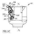
[0027]図1A〜1Dを参照すると、工具12と、それにクランプされた少なくとも1つの切削インサート14とを含む例示的な工具アセンブリ10が示されている。例示された工具12は、フライス工具ヘッドである。
Detailed description
[0027] Referring to FIGS. 1A-1D, an
[0028]この非限定的な例では、工具アセンブリ10は、被加工物(図示せず)を、工具軸ATの周りで回転方向DRに回転させることによって、フライス加工するように構成されている。回転方向は、この非限定的な例では、図1Bに示すように、反時計回りとし得る。
[0028] In this non-limiting example, the
[0029]図2も参照して説明すると、工具12は、工具ベース面18を含むインサート着座領域16と、インサート着座領域16の両側に配置された工具内側領域および工具周辺領域20、22と、工具滑り止め構成部24とを含み得る。
[0029] Referring also to FIG. 2, the
[0030]より正確には、工具滑り止め構成部24は、工具ベース面18に隣接して形成された第1および第2の工具当接面26A、26Bと、工具作動面30を含むクランプ28とを含み得る。
[0030] More precisely, the
[0031]クランプ28は、工具内側領域20に配置され得る。工具作動面30は、工具ベース面18に対して交差する方向に向けられ得る。より正確には、工具作動面30は、工具ベース面18に垂直になるように向けられ得る。そのような向きは、切削インサート14の位置を変化させ得る曲げ力がクランプ28に加えられないようにするのを助け得る。
[0031] The
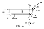
[0032]ここで同様に図3A〜3Cを参照して説明すると、切削インサート14は、インサート周辺面36によって接続された、対向するインサート頂面およびインサートベース面32、34と、少なくとも1つの切れ刃38と、インサートベース面34に隣接して形成されたインサート滑り止め構成部40とを含み得る。より正確には、インサート滑り止め構成部40は、インサートベース面34から、インサート頂面32から離れる方向に延在し得る。
[0032] Referring now also to FIGS. 3A-3C, the cutting
[0033]インサート滑り止め構成部40は、第1および第2のインサート当接面42A、42Bと、インサートベース面34に対して交差する方向に向けられたインサート作動面44とを含み得る。それゆえ、切削インサート14の周辺45は、インサート周辺面36だけでなく、インサートベース面34に対して交差する方向に向けられたインサート作動面44および第1および第2のインサート当接面42A、42Bも含むとみなし得る。
[0033] The insert anti-slip component 40 may include first and second insert abutment surfaces 42A, 42B and an insert actuation surface 44 oriented in a direction intersecting the
[0034]第1および第2の工具当接面26A、26B(図1D)および第1および第2のインサート当接面42A、42B(図3D)は、互いに係合するように構成されている。図2および図3Cから最もよく分かるように、当接面26A、26B、42A、42Bは、対応する形状(この例では直線状)および向きを有し、かつ互いに180°未満の切削インサート当接角または工具当接角YCA、YTAで延在し得る。この例では、値は約40°である。この非限定的な例では、各対の当接面は、それぞれ、楔形の配置構成を形成する。 [0034] The first and second tool abutment surfaces 26A, 26B (FIG. 1D) and the first and second insert abutment surfaces 42A, 42B (FIG. 3D) are configured to engage each other. . As best seen in FIGS. 2 and 3C, the abutment surfaces 26A, 26B, 42A, 42B have corresponding shapes (in this example, straight) and orientations, and cutting insert abutments that are less than 180 ° from each other. It can extend at corners or tool abutment angles Y CA , Y TA . In this example, the value is about 40 °. In this non-limiting example, each pair of abutment surfaces each forms a wedge-shaped arrangement.
[0035]切削インサート14を工具12にクランプするために、切削インサート14は、インサートベース面34が工具ベース面18に接触する位置において、工具12に装着される。換言すると、切削インサート14は、その工具ベース面18およびインサートベース面34を介して工具12に載置し得る。その後、クランプの工具作動面30はインサート作動面44に押し当てられるように片寄らせられて、第1および第2のインサート当接面42A、42Bがそれぞれ第1および第2の工具当接面26A、26Bに押し当てられるように片寄らせられるようにする。換言すると、クランプ位置では、工具12および切削インサート14の唯一の接触面は、工具ベース面18およびインサートベース面34、クランプ工具作動面30およびインサート作動面44、および第1および第2のインサート当接面42A、42Bおよび工具当接面26Aおよび26Bである。
In order to clamp the cutting
[0036]そのようなクランピングは、工具ベース面に沿った切削インサートの滑りを防止するのに好都合とし得ることを理解されたい。なぜなら、切削インサートは、その3つの面、すなわちそのインサート作動面、および第1および第2のインサート当接面で同時にクランプし得るためである。非平行当接面の場合、同時に3点での接触を達成でき、3点(または3つの面)は、非線形の構成に配置されているため、三角形配置を構成し得ることを理解されたい。特に、当接面および作動面のそのような配置は、工具に対する切削インサートの、ベース平面PB(図1Bおよび図2)に沿った並進移動および回転を防止するのに好適である。ベース平面は、工具ベース面18およびインサートベース面34に平行である。
[0036] It should be understood that such clamping may be advantageous to prevent slippage of the cutting insert along the tool base surface. This is because the cutting insert can be clamped simultaneously on its three surfaces, namely its insert working surface and the first and second insert abutment surfaces. It should be understood that in the case of non-parallel abutment surfaces, contact at three points can be achieved at the same time, and the three points (or three surfaces) are arranged in a non-linear configuration and can therefore constitute a triangular arrangement. In particular, such an arrangement of the abutment surface and the working surface is suitable for preventing translational movement and rotation of the cutting insert relative to the tool along the base plane P B (FIGS. 1B and 2). The base plane is parallel to the
[0037]別の利点は、切削方向DC(図2)に工具作動面30を片寄らせることによって、おそらく達成され得る。切削インサート14が摺動するまたは所望の位置から動かされるという傾向は、被加工物(図示せず)と接触しているときに、そのアクティブな第1の切削端部46(図1C)において最大である得ることを理解されたい。工具から外側に向けてクランプ力を加えて切削インサートのアクティブな第1の切削端部46を固定することによって、切削インサートまたはアクティブな第1の切削端部46の正確な位置の維持が達成可能である。
[0037] Another advantage may possibly be achieved by biasing the
[0038]切削方向DCは、工具内側領域20から工具周辺領域22の方へ延在すると定義し得る。より正確には、切削インサートは、通常、工具の周辺部に装着され、かつ通常、工具から突出して、工具ではなく切削インサートのみが被加工物(図示せず)と、確実に接触するようにする。それゆえ、工具12に装着されるときには、そのような工具周辺領域22は、切削インサート14の突出する切れ刃38に近接した周辺縁部48(図1D)を含むとみなすことができるか、または、切削インサート14が工具12に装着されていないときには、工具周辺領域22は、インサート着座領域16を取り囲む周辺縁部48であるとみなすことができる。換言すると、すなわち切削インサート14に関して、切削方向は、その非切削端部50(図1C)から、アクティブな第1の切削端部46の方へ延在するとみなし得る。
[0038] The cutting direction D C may be defined as extending from the tool
[0039]切削インサート14および/または工具12を、切削インサート14の周辺45と接触する工具12の唯一の面が工具作動面30および第1および第2の工具当接面26A、26Bであるように、構成し得ることに留意されたい。換言すると、工具12から上方に延在する工具の面、または、インサート周辺面36に隣接する面、例えば工具壁面52A、52B(図1Cおよび図2)は、切削インサート14から離間している。そのような工具壁面はインサート周辺面36に接触せず、インサート周辺面は、この例では頂面32との交点に切れ刃38を形成する。工具12は、異なる形状の切削インサートを保持するのに好適とし得る。さらに換言すると、上述の構造は、異なる形状の切削インサートを保持する工具を構成し得る(たとえ、対応する形状の滑り止め構成部を有しても)。その結果、切削インサートまたは工具が、離間した滑り止め構成部および切れ刃または工具壁面をそれぞれ有することを、好都合とし得る。
[0039] The only surface of the
[0040]さらに、例示的なより具体的な例を以下説明する。 [0040] Further, more specific illustrative examples are described below.
[0041]この例では、切れ刃38は、インサート頂面32とインサート周辺面36との交点全体に沿って延在する。しかしながら、図1Cに示す装着位置では、この非限定的な例では、アクティブな第1の切削端部46は、第1および第2の横方向切れ刃(lateral cutting edge)部分54A、54Bと、それらの間に延在する前切れ刃(end cutting edge)部分54Cとを含む縁部の一部分のみを含む。
In this example, the
[0042]インサート頂面32、アクティブな第1の切削端部46に隣接するその少なくとも一部分(36A;図1C)は、切り屑(図示せず)が上を通過するすくい面として構成され、およびそれに隣接したインサート周辺面36の少なくとも一部分は、逃げ面として構成され得る。
[0042] The insert
[0043]図3Cに注目すると、切削インサート14は、インサートベース面34に垂直に延在するインサート切削平面PICと、インサート縦断平面PILとを含み得る。インサート縦断平面PILは、切削インサート14を通って長手方向に延在し、対向する第1および第2の切削端部46、46’を接続し、かつインサートベース面34に垂直である。インサート切削平面PICは、理論的に、切削インサート14を仮想的な第1および第2のインサート半体56A、56Bに分ける面である。図示の通り、第1および第2のインサート当接面42A、42Bは、少なくとも部分的に第1のインサート半体56Aに配置され、かつインサート作動面44は、第2のインサート半体56Bに配置され得る。非限定的な本例では、第2の当接面42Bの全体が第1のインサート半体56Aに配置される。
[0043] Turning to FIG. 3C, the cutting
[0044]インサート作動面44および/または工具作動面30は、それら2つの少なくとも一方および好ましくは双方が非尖頭的な形状を有する場合に、安定した係合により好適とし得ることを理解されたい。
[0044] It should be understood that the insert actuation surface 44 and / or the
[0045]少なくとも図3Dをみると、すなわち拡大しないでみると、インサート作動面44は、平らに見え、それゆえ、インサート作動平面PIA内に存在するとし得ることが分かる。 [0045] Turning to at least FIG. 3D, that is, try not expanded, insert actuating surface 44 is flat appearance, therefore, it can be seen, which may be a present in the insert working plane P IA.
[0046]インサート作動平面PIAを、インサートベース面34に対して交差する方向に向けて、インサート作動面がインサート頂面32から離れる方向に延在し得るように、かつインサート作動面44が直線を辿り得るようにすることができる。より正確には、インサート作動平面PIAは、インサートベース面34に垂直に向けられ得る。
[0046] The insert working surface PIA is oriented in a direction intersecting the
[0047]クランプ28が工具12に装着されると、工具作動面30は工具ベース面18に垂直に延在し得る。
[0047] When the
[0048]インサートベース面34に対してインサート作動面44および/または工具作動面30が垂直の向きであることによって、切削インサート14の不安定化を回避するのを支援し得る。
[0048] The orientation of the insert actuation surface 44 and / or the
[0049]第1および第2のインサート当接面42A、42Bおよびインサート作動面44は、第1の切削端部46に関連付けられる第1の組の係合面を構成する。
[0049] The first and second insert abutment surfaces 42A, 42B and the insert actuation surface 44 constitute a first set of engagement surfaces associated with the first cutting
[0050]図3Eを参照して説明すると、この第1の組のインサート作動面44は他の2つの面の間に延在でき、これら面は、本例(スローアウェイチップを示す)では、第2の追加的な組の係合面に属しかつ第2の切削端部46’に関連付けられる追加的な第1および第2のインサート当接面42A’、42B’とし得る。追加的な第1および第2のインサート当接面42A’、42B’は、インサート作動面44との接続点とし得る端点58A、58Bを含み得る。
[0050] Referring to FIG. 3E, this first set of insert actuation surfaces 44 can extend between the other two surfaces, which in this example (showing a throwaway tip), There may be additional first and second
[0051]非尖頭的な作動面(すなわちインサート作動面44および/または工具作動面30)を使用するとき、一貫性のあるまたは制御された力を加える方向を達成する有益な効果があり得ることが分かった。言い換えると、切削インサートは、正確で安定的な装着配置構成を最適に達成するために、正確な方向に向けられ得る。尖頭的(すなわち、図3Eに符号60を付す仮想線によって示すように曲率半径が小さい、または平面図においてV字形状の)作動面は、特に、切削インサートまたは関連の工具に切削力を加える間、加えられた力を、一貫性のないまたは制御されていない方向に向けやすい傾向を有することを理解されたい。 [0051] When using a non-pointing working surface (ie, insert working surface 44 and / or tool working surface 30), there may be a beneficial effect of achieving a consistent or controlled force application direction. I understood that. In other words, the cutting insert can be oriented in the correct direction to optimally achieve an accurate and stable mounting arrangement. A pointed (ie, a small radius of curvature as shown by the phantom line labeled 60 in FIG. 3E, or V-shaped in plan view) in particular applies cutting forces to the cutting insert or associated tool. In the meantime, it should be understood that the applied force tends to be directed in an inconsistent or uncontrolled direction.
[0052]特に、図3Dに示す例示的なインサート作動面44は、遠方から平面的にみると平ら/直線に見えるが、拡大するとわずかに凸面の曲率を示す。これは、意外にも、最も好ましい構成は、非常にわずかに湾曲した、好ましくは(例えば図3Eに概略的に例示するように)凸状に湾曲したインサート作動面(あるいは、非常にわずかに凸状に湾曲した工具作動面)であり、これにより、その単一の点での、正確で一貫性のある接触を可能にし得ることが分かったためである。最も好ましい構成は、代替的な作動面(すなわち凸状に湾曲していない作動面、この例では工具作動面30)が平らである(すなわち曲率を有しない)構成であることも分かった。
[0052] In particular, the exemplary insert actuation surface 44 shown in FIG. 3D appears flat / straight when viewed in plan from a distance, but exhibits a slightly convex curvature when magnified. This is surprisingly because the most preferred configuration is a very slightly curved, preferably curved, insert working surface (or, for example, as schematically illustrated in FIG. 3E) (or very slightly convex). This is because it has been found that this can enable accurate and consistent contact at that single point. It has also been found that the most preferred configuration is an alternative working surface (i.e., non-convexly curved working surface,
[0053]本出願の主題を発展させる最中、最も好ましい構成は、平らなインサート作動面44と共にわずかに凸状に湾曲した工具作動面30(図示の非拡大図では見えない)であることが分かった。しかしながら、代替的な配置構成(すなわちインサート作動面44が湾曲しており、および工具作動面30が平らである)を提供すること、または両面ともわずかな曲率を有することが、依然として実現可能である。それにもかかわらず、最も好ましい構成は、代替的な作動面(すなわち、凸状に湾曲していない作動面、この場合インサート作動面44)が平らである(すなわち曲率がない)構成であると考えられる。
[0053] In developing the subject matter of this application, the most preferred configuration is a slightly convexly curved tool actuation surface 30 (not visible in the unexpanded view shown) with a flat insert actuation surface 44. I understood. However, it is still feasible to provide an alternative arrangement (i.e. the insert working surface 44 is curved and the
[0054]詳述するために、この例ではインサート作動面44である非尖頭的な作動面は、より正確には、追加的な第1および第2のインサート当接面42A’、42B’(またはインサート作動面44に接続された他の面)の接線の部分に沿って延在しない、すなわち自由な曲率を有すると定義され得る。
[0054] To elaborate, the non-pointing actuation surface, which in this example is the insert actuation surface 44, is more precisely the additional first and second
[0055]さらに詳述するために、および比較のためだけに、図3Eのみを参照すると、理解しやすくするために例示した、誇張して湾曲されたインサート作動面44よりも曲率半径が小さい仮想的な面60が示されている。仮想的な面60は、端点58A、58Bとその中間セクションとの間に部分61A、61Bを有し、それら部分は仮想的な接線62A、62Bの接線方向にある。仮想的な面60は、その曲率半径の小ささに起因して尖っているとみなされる。むしろ、曲率の大きい、または平らであり、かつ端点58Aと58Bとの間に延在する直線的な基準線LRに近づく作動面は、非尖頭的であるとみなされる。図3Eのインサート作動面44は、誇張して湾曲されていると繰り返し、およびそのより現実的な図は図3Dに示されている。要約すると、工具アセンブリ10の作動面30、44の少なくとも一方は、完全に平らでなくても、平らに近づくかまたは平らに向かう傾向を有することが好ましい。代替的な作動面30、44が平らであることも、不可欠ではないが、好ましい。平らであることの傾向に関して、作動面30、44は、接線に沿って延在する曲率を有する仮想的な面60よりも平らである必要がある。好ましくは、そのような作動面30、44は、そのような仮想的な面60よりも平らである必要がある。例えば、仮想的な面60の最も外側の点61Cが、直線的な基準線LRに垂直に、第1の距離D1延在する場合、作動面44の最も外側の点44Aは、好ましくは第2の距離D2延在する必要があり、第2の距離は、第1の距離D1の25%以下、さらに一層好ましくは、第1の距離D1の10%以下である。
[0055] For further details and for comparison purposes only and with reference only to FIG. 3E, a hypothetical curvature radius is smaller than the exaggerated curved insert actuation surface 44, illustrated for ease of understanding. A typical surface 60 is shown. The virtual plane 60 has
[0056]図示はしないが、作動面は、端点58A、58Bにおける単なる半径の中間に変化がある場合、依然として非尖頭的であるとみなされ得ることを理解されたい。これは、非尖頭的であることの目的が、最も外側の点44A、すなわち接触点、または、別の関連の作動面と係合するように構成された作動面44の少なくとも中心部分に最適であるためである。
[0056] Although not shown, it should be understood that the working surface may still be considered non-pointed if there is a change in the middle of a mere radius at the
[0057]図3Dを参照して説明すると、第1および第2のインサート当接面42A、42Bおよびインサート作動面44は、切削インサート14の外側に面している(62A、62Bおよび62Cを付した外向き矢印で示す)。 [0057] Referring to FIG. 3D, the first and second insert abutment surfaces 42A, 42B and the insert actuation surface 44 face the outside of the cutting insert 14 (labeled 62A, 62B and 62C). Indicated by an outward-facing arrow).
[0058]図3Aから最もよく分かるように、第1および第2のインサート当接面42A、42Bおよびインサート作動面44は、インサート頂面32から離れる方向に延在し得る(64を付した下向き矢印で示すように)。 [0058] As best seen in FIG. 3A, the first and second insert abutment surfaces 42A, 42B and the insert actuation surface 44 may extend away from the insert top surface 32 (downwardly labeled 64). As indicated by the arrow).
[0059]ここで図3Bを参照して説明すると、図示の非限定的な例では、第1および第2のインサート当接面42A、42B、およびインサート作動面44の全ては、非接触突出下面71を有する単一の突出部分70に形成される(図3B)。インサート作動面44および第1および第2のインサート当接面42A、42Bは、単一の突出部分70に形成され、単一の突出部分自体は、インサートベース面34の中心領域に形成され、かつ全側面はインサートベース面34によってインサート周辺面36から離間し得る。
[0059] Referring now to FIG. 3B, in the illustrated non-limiting example, the first and second insert abutment surfaces 42A, 42B, and the insert actuation surface 44 are all non-contact protruding undersurfaces. Formed into a single protruding
[0060]図示の例示的な切削インサート14は、スローアウェイチップであり、かつインサートベース面34に垂直にかつその中心を通って延びるインサート中心軸AIC(図3D)の周りで180°の回転対称を有し得る。その結果、切削インサート14は、第2のインサート滑り止め構成部40’と一緒に構成できる。第2のインサート滑り止め構成部40’は、上述の追加的な第1および第2のインサート当接面42A’、42B’、および追加的なインサート作動面44’を含み得る。
[0060] The illustrated
[0061]図示の通り、第1および第2のインサート滑り止め構成部40、40’の面42A、42B、44、42A’、42B’、44’は、単一の突出部分70の全側面を形成するか、または単一の突出部分を取り囲む。それゆえ、図示の非限定的な例の切削インサート14の単一の突出部分70は、2組の係合面を有するとみなすことができ、第1の組は面42A、42Bおよび44を含み、および第2の組は面42A’、42B’および44’を含む。
[0061] As shown, the
[0062]図2に示すように、ここで工具滑り止め構成部24の複数の面を参照すると、これら面は、必要な変更を加えて、インサート滑り止め構成部40に対応する特徴を有し得ることを理解されたい。
[0062] Referring now to the plurality of surfaces of the tool
[0063]さらに、第1および第2の工具当接面26A、26Bおよび工具作動面30は、内側に面し得る(すなわち、72A、72Bおよび72Cを付した内向き矢印で示すように、インサート着座領域16の中心の方へ)。
[0063] Further, the first and second tool abutment surfaces 26A, 26B and the
[0064]第1および第2の工具当接面26A、26Bおよび工具作動面30は、インサート着座領域16へと凹ませ得る。換言すると、第1および第2の工具当接面26A、26Bおよび工具作動面30は、インサート着座領域16に形成された凹部74の側面とし得る。
[0064] The first and second tool abutment surfaces 26A, 26B and the
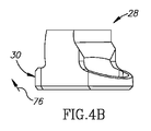
[0065]図示の例示的な工具作動面30および第1および第2の工具当接面26A、26Bは工具ベース面18に垂直とするが、それら面はまた、上向き−内向き方向に少なくとも部分的に傾斜し得る(例えば、図4Bに示すように、工具作動面30は、76を付した矢印によって示す上向き−内向き方向に傾斜している)。同様に、図示の例示的なインサート作動面44および第1および第2のインサート当接面42A、42Bはインサートベース面34に垂直であるが、それら面はまた、下向き−外向き方向に少なくとも部分的に傾斜し得る(例えば、インサート作動面44は、66を付す矢印で示す下向き−外向き方向に傾斜し得る;比較のために、68を付す矢印は、下向き−内向き方向に向けられている)。
[0065] Although the illustrated exemplary
[0066]図3Dを参照して説明すると、インサート当接面平面、例えば第1および第2のインサート当接面平面P1、P2があり、その各々がインサート作動面平面PIAに平行し得ることを理解されたい。第1のインサート当接面平面P1は、インサート作動面平面PIAに近いこと、および第1のインサート当接面平面P1上に存在する第1および第2のインサート当接面42A、42Bの一対の点78A、78Bが、第2のインサート当接面平面P2上に存在する一対の点80A、80Bよりも大きな距離で互いに離間していることに留意されたい。それゆえ、引き続き図3Dを参照して説明すると、第1の組の係合面に属する第1および第2のインサート当接面42A、42Bは、第2の組の係合面に属する追加的なインサート作動面44’の方向かつまた関連の第1の切削端部46の方向に向かって、狭まる。同様に、第2の組の係合面に属する追加的な第1および第2のインサート当接面42A’、42B’は、第1の組の係合面に属するインサート作動面44の方向かつまた関連の第2の切削端部46’ の方向に向って、狭まる。
[0066] Referring to FIG. 3D, there are insert abutment planes, eg, first and second insert abutment planes P 1 , P 2 , each of which is parallel to the insert actuation surface plane PIA. Please understand that you get. First insert abutment surface plane P 1 is closer to the insert working surface plane P IA, and the first of the first and second
[0067]上記の構造はまた、必要な変更を加えて、工具滑り止め構成部24も可能とし得る(例えば図5Aを参照、工具作動面平面PTAがインサート作動面平面PIAに対応し;第1および第2の工具当接面平面P3およびP4が第1および第2のインサート当接面平面P1、P2に対応し;点78C、78Dが点78A、78Bに対応し;および点80C、80Dが点80A、80Bに対応する)。その結果、工具当接面26A、26Bは、工具周辺領域22の方へ向かう傾向を有するとき、狭まる。
[0067] The above structure may also allow the tool
[0068]図3Aおよび図3Bを参照して説明すると、第1および第2のインサート当接面42A、42Bが形成される突出部分70は、インサート周辺面36から全体的に離間し得る。換言すると、インサートベース面34は、インサート周辺面36全体に沿って連続的に延在し、かつ第1および第2のインサート当接面42A、42Bおよびインサート作動面44を完全に囲み得る。ベース面34は平らとし得る。
[0068] Referring to FIGS. 3A and 3B, the protruding
[0069]上述の特徴のいずれか、例えば連続的なインサートベース面34、切削インサートの周辺に沿って延在するベース面、平らなベース面などは、切削インサートを工具に安定的に装着し得ることを理解されたい。
[0069] Any of the features described above, such as a continuous
[0070]上述の構造的特徴のいずれかはまた、必要な変更を加えて、工具ベース面18にも可能とし得る。しかしながら、工具ベース面18は、例えば、クランプ28によって完成される部分を除いて、インサート周辺面全体に沿って延在し得る。特に、工具ベース面18は、第1および第2の工具当接面26A、26Bを接続する、すなわち第1の当接面26Aから第2の当接面26Bまで連続的な壁を提供する。そのような接続は、切削作業の最中の第1および第2の工具当接面26A、26Bの撓み(特に高速で著しい)に対する、追加的な構造強度をもたらし得る。
[0070] Any of the structural features described above may also be enabled on the
[0071]図1Dおよび図2を参照して説明すると、第1の工具当接面26Aに隣接する工具ベース面18の第1の部分80は、工具軸ATに近い工具ベース面18の第2の部分82よりも、その下にある材料が少ない(図1C)。そのような場合には、工具ベース面18の第1の部分80を工具ベース面18の第2の部分82よりも大きく形成することにより、特にこのようなシリンダー状の工具では、好都合な構造強度をもたらし得ることが分かった。
[0071] Referring to FIGS. 1D and 2, the
[0072]そのような拡大は、第1の部分80を広くすることによって達成できる。例えば、第1の工具当接面26Aからそれに対して垂直に延在する、工具ベース面18の第1の部分80の第1の工具ベース幅WT1は、第2の工具当接面26Bからそれに対して垂直に延在する、第2の工具ベース幅WT2よりも大きいとし得る。
[0072] Such enlargement can be achieved by widening the
[0073]インサートベース面34は、工具ベース面18に対応するように構成できる。例えば、図3Dを参照して説明すると、第1のインサート当接面42Aからそれに対して垂直に延在する、インサートベース面34の第1のインサートベース幅WI1は、第2のインサート当接面42Bからそれに対して垂直に延在する、第2のインサートベース幅WI2よりも大きいとし得る。
[0073] The
[0074]切削インサートは工具に様々な方法でクランプし得ると理解されるが、以下は、例示的なクランプ構成部である。 [0074] While it will be appreciated that the cutting insert may be clamped to the tool in various ways, the following are exemplary clamping components.
[0075]工具およびインサートベース面18、34は、バイアス構成部84(図1D)によって互いに対してクランプし得る。このバイアス構成部84または異なる装置は、いずれの場合にも、工具ベース面から離れる方向に切削インサートを動かさないように構成し得る。 [0075] The tool and insert base surfaces 18, 34 may be clamped against each other by a biasing component 84 (FIG. 1D). This bias arrangement 84 or different device may be configured in any case not to move the cutting insert away from the tool base surface.
[0076]バイアス構成部84は、切削インサート14の貫通孔88と、工具12に形成されたネジ孔90とを通って延在するように構成されたバイアス構成ネジ86を含むことができ、それらの孔にバイアス構成ネジ86を固定できる。
[0076] The bias component 84 may include a bias component screw 86 configured to extend through the through-
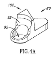
[0077]図1D、および図4A〜4Dに注目すると、クランプ28は、クランプ28に形成されたクランプボア95(図4D)を介してクランプネジ97を収容するように構成できる。
[0077] Turning attention to FIGS. 1D and 4A-4D, the
[0078]より正確には、クランプ28は、工具作動面30と、クランプネジ97によって当接されるように含まれるクランプボアとの間に配置された、傾斜クランプ面92を含み得る。
[0078] More precisely, the
[0079]傾斜クランプ面92は、上向きに突出するクランプ隆起102(すなわち、実質的に平面的な形状のクランプ28の残りの部分から上向きに突出する)に形成できる。
[0079] The
[0080]クランプは、おそらく、曲げられる部分を含み、それにより、工具作動面の位置または向きを変化させ得るが、図示の非限定的な例は、クランプネジ97によって係合されると、クランプ28全体が動くことができるものである。 [0080] The clamp may possibly include a portion that can be bent, thereby changing the position or orientation of the tool actuation surface, but the non-limiting example shown is The whole 28 can move.
[0081]バイアス構成ネジ86が、通常、ベース平面PBに沿った滑りを制限できるときに、バイアス構成部84または異なる装置は、工具ベース面18に沿った切削インサート14の滑りを可能にするように構成し得ることを理解されたい。
[0081] Bias configuration screw 86, usually, when you can limit the sliding along the base plane P B, the bias component 84 or a different device allows sliding of the cutting
[0082]それゆえ、工具12への切削インサート14のクランプは、工具ベース面18に沿った、切削インサートのインサートベース面34の摺動運動を含み得る。
[0082] Therefore, clamping of the cutting
[0083]特に、工具作動面30は、細長くかつ平板状のクランプ突起104の端部に形成されている。クランプ突起104は、上向きに突出するクランプ隆起102から工具作動面30まで延在する。細長い形状であることによって、工具作動面30はインサート作動面44に到達できる。
In particular, the
[0084]インサートと工具壁との間のクランプの少なくとも一部分を楔形にすることによって、安定的なクランプ構成部をもたらすことができることが分かった。 [0084] It has been found that at least a portion of the clamp between the insert and the tool wall can be wedged to provide a stable clamping component.
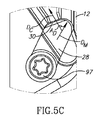
[0085]例えば、図5A〜5Cを参照して説明すると、クランプ28は、切削方向DCに対して交差する方向である運動方向DMに動くことができる。図5Bは、工具作動面30とインサート作動面44との間に間隙98がある第1の位置を示し、および図5Cは、工具作動面30とインサート作動面44との接触を示す。
[0085] For example, referring to FIG. 5A-5C, the
[0086]図2から最もよく分かるように、工具12は、内壁96によって囲まれたトラック94を備えて形成され得る。前記楔形は、インサート作動面44と内壁96との間に生じ得る。
[0086] As best seen in FIG. 2, the
[0087]切削方向DCと運動方向DMとの間に形成された方向内角ADは、鋭角とし得る。好ましくは、方向内角ADは30°〜80°とし得る。 [0087] direction inner angle A D formed between the cutting direction D C and the direction of movement D M may be an acute angle. Preferably, the direction internal angle AD may be 30 ° to 80 °.
[0088]図4Dを参照して説明すると、クランプ壁面100と工具作動面30(またはその少なくとも延在部分)との間のクランプ内角αは鋭角とし得る。クランプ内角αは、条件30°<α<80°を満たし得る。
[0088] Referring to FIG. 4D, the clamp interior angle α between the
[0089]上記の説明は、必要に応じて、特許請求する主題の実施可能性のための1つ以上の例示的な実施形態および詳細を含み、および本出願の特許請求の範囲から、例示されていない実施形態および詳細を排除しない。 [0089] The foregoing description includes, as appropriate, one or more exemplary embodiments and details for the feasibility of the claimed subject matter, and is exemplified from the claims of this application. Embodiments and details not excluded are not excluded.
Claims (42)
前記インサート滑り止め構成部は、互いにおよび前記インサートベース面に対して非平行である第1および第2のインサート当接面と、非尖頭的な形状を有し、かつ前記インサートベース面に対して交差する方向に向けられたインサート作動面平面内に存在するインサート作動面とを含み;
前記第1および第2のインサート当接面の最接近点の複数の対は、前記インサート作動面平面に平行なそれぞれの共通のインサート当接面平面内に存在して、予め決められた距離だけ離間しており;および
前記予め決められた距離の少なくとも1つは、前記インサート作動面平面からさらに遠くに離間した一対の点に関連付けられた別の予め決められた距離よりも大きい、切削インサート。 A cutting insert comprising opposed insert top and insert base surfaces, at least one cutting edge, and an insert anti-slip component formed adjacent to the insert base surface, connected by an insert peripheral surface. ;
The insert anti-slip component has first and second insert abutment surfaces that are non-parallel to each other and to the insert base surface, and has a non-pointed shape, and with respect to the insert base surface An insert working surface that lies in the plane of the insert working surface oriented in a crossing direction;
A plurality of pairs of closest points of the first and second insert abutment surfaces are present in respective common insert abutment planes parallel to the insert actuation surface plane and are a predetermined distance. A cutting insert that is spaced; and wherein at least one of the predetermined distances is greater than another predetermined distance associated with a pair of points spaced further away from the insert working surface plane.
前記工具滑り止め構成部は、前記工具ベース面に隣接して形成されかつ互いにおよび前記工具ベース面に対して非平行である第1および第2の工具当接面と、前記工具内側領域に配置されかつ前記工具ベース面に対して交差する方向に向けられた工具作動面平面内に存在する工具作動面を含むクランプとを含み;
前記第1および第2の工具当接面の最接近点の複数の対は、前記工具作動面平面に平行なそれぞれの共通の工具当接面平面内に存在して、予め決められた距離だけ離間しており;
前記予め決められた距離の少なくとも1つは、前記工具作動面平面からさらに遠くに離間した一対の点に関連付けられた別の予め決められた距離よりも大きく;および
前記クランプは、前記工具作動面を介して前記切削方向に力を加えるように構成されている、工具。 An insert seating region having a cutting direction and including a tool base surface, a tool inner region and a tool peripheral region disposed on both sides of the insert seating region, wherein the cutting direction is from the tool inner region to the tool A tool comprising a tool inner region and a tool peripheral region, defined as extending toward the peripheral region, and a tool anti-slip component;
The tool anti-slip component is disposed in the tool inner region, and first and second tool contact surfaces formed adjacent to the tool base surface and non-parallel to each other and the tool base surface. And a clamp including a tool actuation surface that lies in a plane of the tool actuation surface that is oriented in a direction intersecting the tool base surface;
A plurality of pairs of closest points of the first and second tool abutment surfaces are present in respective common tool abutment planes parallel to the tool actuation surface plane and are a predetermined distance away. Spaced apart;
At least one of the predetermined distances is greater than another predetermined distance associated with a pair of points further away from the tool working surface plane; and A tool configured to apply a force in the cutting direction through the tool.
前記工具滑り止め構成部が、前記工具ベース面に隣接して形成されかつ互いにおよび前記工具ベース面に対して非平行である第1および第2の工具当接面と、前記工具内側領域に配置されかつ前記インサートベース面に対して交差する方向に向けられた工具作動面を含むクランプとを含み;
前記切削インサートが、インサート周辺面によって接続される、対向するインサート頂面およびインサートベース面と、少なくとも1つの切れ刃と、前記インサートベース面に隣接して形成されたインサート滑り止め構成部とを含み;
前記インサート滑り止め構成部が、互いにおよび前記インサートベース面に対して非平行である第1および第2のインサート当接面と、前記インサートベース面に対して交差する方向に向けられたインサート作動面とを含み;
前記切削インサートおよび前記工具が、前記インサートベース面が前記工具ベース面に接触する位置に構成され;および
前記クランプが、前記工具作動面を前記インサート作動面に押し当てるように片寄らせ、それゆえ前記第1および第2のインサート当接面を前記第1および第2の工具当接面に押し当てるように片寄らせて、前記切削インサートの前記工具ベース面に沿った滑りを防止するように構成されている、工具アセンブリ。 A tool assembly comprising a combination of a tool configured to cut in a cutting direction and a cutting insert mounted on the tool, the tool comprising an insert seating area including a tool base surface, and the insert seating area A tool inner region and a tool peripheral region disposed on both sides of the tool, wherein the cutting direction is defined as extending from the tool inner region toward the tool peripheral region, and a tool. A non-slip component;
The tool anti-slip component is disposed in the tool inner region and first and second tool abutment surfaces formed adjacent to the tool base surface and non-parallel to each other and the tool base surface And a clamp including a tool actuation surface oriented in a direction intersecting the insert base surface;
The cutting insert includes opposed insert top and insert base surfaces connected by an insert peripheral surface, at least one cutting edge, and an insert anti-slip component formed adjacent to the insert base surface. ;
First and second insert abutment surfaces that are non-parallel to each other and to the insert base surface, and an insert working surface that is oriented in a direction intersecting the insert base surface Including:
The cutting insert and the tool are configured at a position where the insert base surface contacts the tool base surface; and the clamp biases the tool working surface against the insert working surface, and therefore the The first and second insert abutment surfaces are offset so as to press against the first and second tool abutment surfaces to prevent slippage of the cutting insert along the tool base surface. The tool assembly.
a.前記切削インサートを、前記工具上の、前記インサートベース面が前記工具ベース面に接触する位置に装着するステップ;および
b.前記クランプの工具作動面を前記インサート作動面に押し当てるように片寄らせ、それにより、前記第1および第2のインサート当接面をそれぞれ前記第1および第2の工具当接面に押し当てるように片寄らせて、前記工具ベース面に沿った前記切削インサートの滑りを防止するステップ
を含む方法。 A method for clamping a cutting insert to a tool comprising: an insert seating region including a tool base surface; a tool inner region and a tool peripheral region disposed on both sides of the insert seating region; and a tool non-slip component First and second tool abutment surfaces formed adjacent to the tool base surface and non-parallel to each other and to the tool base surface; and the tool A clamp disposed at an inner region and including a tool actuation surface oriented in a direction intersecting the tool base surface; and an opposing insert top surface and insert wherein the cutting insert is connected by an insert peripheral surface A base surface, at least one cutting edge, and an insert anti-slip component formed adjacent to the insert base surface; The insert anti-slip component includes first and second insert abutment surfaces that are non-parallel to each other and the insert base surface, and an insert operation surface that is oriented in a direction intersecting the insert base surface Said method comprising:
a. Mounting the cutting insert on the tool at a location where the insert base surface contacts the tool base surface; and b. The tool operating surface of the clamp is biased to press against the insert operating surface, thereby pressing the first and second insert abutting surfaces against the first and second tool abutting surfaces, respectively. A method of preventing the cutting insert from slipping along the tool base surface.
Applications Claiming Priority (3)
| Application Number | Priority Date | Filing Date | Title |
|---|---|---|---|
| US13/490,197 | 2012-06-06 | ||
| US13/490,197 US20130330136A1 (en) | 2012-06-06 | 2012-06-06 | Cutting Insert and Tool Having an Anti-Slip Arrangement |
| PCT/IL2013/050473 WO2013183045A1 (en) | 2012-06-06 | 2013-06-03 | Cutting insert and tool having an anti-slip arrangement |
Publications (2)
| Publication Number | Publication Date |
|---|---|
| JP2015522433A true JP2015522433A (en) | 2015-08-06 |
| JP2015522433A5 JP2015522433A5 (en) | 2016-06-30 |
Family
ID=48794147
Family Applications (1)
| Application Number | Title | Priority Date | Filing Date |
|---|---|---|---|
| JP2015515645A Pending JP2015522433A (en) | 2012-06-06 | 2013-06-03 | Cutting insert and tool with non-slip components |
Country Status (9)
| Country | Link |
|---|---|
| US (2) | US20130330136A1 (en) |
| EP (1) | EP2858775B1 (en) |
| JP (1) | JP2015522433A (en) |
| KR (1) | KR20150020286A (en) |
| CN (1) | CN104334302B (en) |
| BR (1) | BR112014027164A2 (en) |
| CA (1) | CA2870797C (en) |
| RU (1) | RU2014153153A (en) |
| WO (1) | WO2013183045A1 (en) |
Families Citing this family (14)
| Publication number | Priority date | Publication date | Assignee | Title |
|---|---|---|---|---|
| KR101452073B1 (en) * | 2012-12-24 | 2014-10-16 | 대구텍 유한회사 | Cutting insert and milling cutter having the same |
| US9120154B2 (en) * | 2013-02-14 | 2015-09-01 | Iscar, Ltd. | Single-sided square-shaped indexable cutting insert and cutting tool |
| US9475136B2 (en) * | 2013-07-30 | 2016-10-25 | Kennametal Inc. | High-speed milling cutter and cutting insert therefor |
| US9481038B2 (en) * | 2013-12-11 | 2016-11-01 | Iscar, Ltd. | Cutting insert having a dovetail anti-slip arrangement |
| EP3000549B1 (en) * | 2014-09-24 | 2022-11-09 | Sandvik Intellectual Property AB | A cutting tool and a cutting insert for a chip-removing tool |
| US10239134B2 (en) * | 2015-05-19 | 2019-03-26 | Tungaloy Corporation | Tool body and cutting tool |
| EP3153261B1 (en) * | 2015-10-09 | 2018-04-04 | Sandvik Intellectual Property AB | Turning insert and method |
| CN106270699B (en) * | 2016-08-31 | 2018-02-06 | 嘉兴市海拓环宇机械有限公司 | CNC milling machine special-purpose milling cutter |
| US10144071B2 (en) * | 2017-03-16 | 2018-12-04 | Iscar, Ltd. | Tool holder having position adjustment arrangement and cutting tool |
| KR102011329B1 (en) | 2017-12-29 | 2019-08-14 | 한국야금 주식회사 | Cutting insert and cutting tool mounted with the same |
| US11090740B2 (en) | 2019-02-12 | 2021-08-17 | Iscar, Ltd. | Rotary cutting body having insert pocket with seat surface provided with a plurality of abutment elements and rotary cutting tool |
| JP7281532B2 (en) | 2019-03-05 | 2023-05-25 | 京セラ株式会社 | Turning tool and manufacturing method of machined product |
| US11097362B2 (en) | 2019-12-10 | 2021-08-24 | Iscar, Ltd. | Cutting insert having two upper cutting edges and a lower central protuberance with four abutment walls defining an imaginary quadrilateral, and rotary cutting tool |
| US11491560B1 (en) * | 2021-07-13 | 2022-11-08 | Taegutec Ltd. | Cutting insert and rotary cutting tool including same |
Citations (4)
| Publication number | Priority date | Publication date | Assignee | Title |
|---|---|---|---|---|
| GB271208A (en) * | 1926-03-25 | 1927-05-26 | John Henry Barker | Improvements in and relating to turning, boring, and the like cutting tools and holders for the same |
| JPH09506044A (en) * | 1994-03-31 | 1997-06-17 | ケンナメタル インコーポレイテッド | Cutting tool assembly and cutting tool bit |
| JP2001328012A (en) * | 2000-05-19 | 2001-11-27 | Daishowa Seiki Co Ltd | Cutting tool |
| US20080166191A1 (en) * | 2006-12-12 | 2008-07-10 | Sandvik Intellectual Property Ab | Tool and a cutting insert for chip removing machining |
Family Cites Families (16)
| Publication number | Priority date | Publication date | Assignee | Title |
|---|---|---|---|---|
| DE2948544A1 (en) | 1979-12-03 | 1981-06-11 | Sandvik GmbH, 4000 Düsseldorf | KNIFE HEAD FOR HIGH-SPEED ROLL MILLING |
| US5167473A (en) * | 1991-06-24 | 1992-12-01 | Allied-Signal Inc. | Unidirectional insert lock |
| SE508387C2 (en) * | 1993-05-26 | 1998-10-05 | Sandvik Ab | round Cut |
| DE4334852C2 (en) * | 1993-10-13 | 1996-10-02 | Karl Zinner | Fuses for cutting knives used in the recesses of a high-speed rotating tool carrier body |
| SE510851C2 (en) * | 1996-12-23 | 1999-06-28 | Sandvik Ab | Cuts and holders for cutting metalworking |
| JPH1119808A (en) * | 1997-06-30 | 1999-01-26 | Ngk Spark Plug Co Ltd | Cutting chip and cutting tool using therewith |
| IL139957A0 (en) | 2000-11-28 | 2002-02-10 | Iscar Ltd | Cutting tool |
| SE516612C2 (en) | 2000-06-27 | 2002-02-05 | Sandvik Ab | Adjusting mechanism for a cutter as well as tools for chip separating machining |
| SE522490C2 (en) * | 2001-01-30 | 2004-02-10 | Sandvik Ab | Tool holder for cutting for chip separating machining with flexible side surface in cutting position |
| SE526539C2 (en) * | 2002-05-28 | 2005-10-04 | Sandvik Intellectual Property | Chip separation machining tool where the cutting position has flexible portions. |
| SE526586C2 (en) * | 2003-11-25 | 2005-10-11 | Sandvik Intellectual Property | Chip separating machining tool including a male / female connection between cutting member and holder part |
| SE529330C2 (en) * | 2005-11-21 | 2007-07-10 | Sandvik Intellectual Property | Tools and cutting body for chip separating machining with elastic connection between cutting body and holder |
| JP5076438B2 (en) * | 2006-01-30 | 2012-11-21 | 三菱マテリアル株式会社 | Insert-type cutting tool and method of fixing insert in insert-type cutting tool |
| SE0600876L (en) * | 2006-04-20 | 2007-10-21 | Sandvik Intellectual Property | Tools and inserts for chip separating machining with primary and secondary meshes with rotationally symmetrical shape |
| SE531502C2 (en) * | 2007-06-05 | 2009-04-28 | Sandvik Intellectual Property | Tools for chip separating machining as well as basic body and indexable cutting for this |
| US7566192B2 (en) * | 2007-10-19 | 2009-07-28 | Kennametal Inc. | Axial seating pin |
-
2012
- 2012-06-06 US US13/490,197 patent/US20130330136A1/en not_active Abandoned
-
2013
- 2013-06-03 CA CA2870797A patent/CA2870797C/en not_active Expired - Fee Related
- 2013-06-03 US US14/398,888 patent/US9573204B2/en active Active
- 2013-06-03 WO PCT/IL2013/050473 patent/WO2013183045A1/en active Application Filing
- 2013-06-03 KR KR1020147033550A patent/KR20150020286A/en not_active Application Discontinuation
- 2013-06-03 BR BR112014027164A patent/BR112014027164A2/en not_active IP Right Cessation
- 2013-06-03 EP EP13737668.7A patent/EP2858775B1/en active Active
- 2013-06-03 RU RU2014153153A patent/RU2014153153A/en not_active Application Discontinuation
- 2013-06-03 JP JP2015515645A patent/JP2015522433A/en active Pending
- 2013-06-03 CN CN201380029723.8A patent/CN104334302B/en active Active
Patent Citations (4)
| Publication number | Priority date | Publication date | Assignee | Title |
|---|---|---|---|---|
| GB271208A (en) * | 1926-03-25 | 1927-05-26 | John Henry Barker | Improvements in and relating to turning, boring, and the like cutting tools and holders for the same |
| JPH09506044A (en) * | 1994-03-31 | 1997-06-17 | ケンナメタル インコーポレイテッド | Cutting tool assembly and cutting tool bit |
| JP2001328012A (en) * | 2000-05-19 | 2001-11-27 | Daishowa Seiki Co Ltd | Cutting tool |
| US20080166191A1 (en) * | 2006-12-12 | 2008-07-10 | Sandvik Intellectual Property Ab | Tool and a cutting insert for chip removing machining |
Also Published As
| Publication number | Publication date |
|---|---|
| KR20150020286A (en) | 2015-02-25 |
| US20150125225A1 (en) | 2015-05-07 |
| CA2870797A1 (en) | 2013-12-12 |
| WO2013183045A1 (en) | 2013-12-12 |
| US20130330136A1 (en) | 2013-12-12 |
| CN104334302B (en) | 2017-08-25 |
| CN104334302A (en) | 2015-02-04 |
| RU2014153153A (en) | 2016-07-27 |
| CA2870797C (en) | 2018-03-20 |
| US9573204B2 (en) | 2017-02-21 |
| BR112014027164A2 (en) | 2017-06-27 |
| EP2858775A1 (en) | 2015-04-15 |
| EP2858775B1 (en) | 2022-10-26 |
Similar Documents
| Publication | Publication Date | Title |
|---|---|---|
| JP2015522433A (en) | Cutting insert and tool with non-slip components | |
| JP6471161B2 (en) | Cutting insert with dovetail anti-slip arrangement | |
| JP2013512787A (en) | Cutting inserts and shims for heavy cutting operations | |
| EP1190795B1 (en) | Cutting tool | |
| US7309193B2 (en) | Indexable insert with corners with different radii | |
| US8465233B2 (en) | Slot-milling tool and slot-milling insert for a slot-milling tool | |
| US10052693B2 (en) | Plate member of cutting tool, tool block, clamp member, and cutting tool | |
| JP5991565B1 (en) | Cutting inserts, tool bodies and cutting tools | |
| JP2012121132A (en) | Cutting insert | |
| US10155324B2 (en) | Cutter head for cutting materials, and cutter therefor | |
| KR20080003202A (en) | Insert-indexable tool | |
| JP2015512798A (en) | Left-handed and right-handed cutting tools | |
| JP2012501861A (en) | Machine tool with adjustable cutting insert | |
| JP6052712B2 (en) | Cutting tools | |
| KR100673633B1 (en) | Cutting tool with oblique cutting edge | |
| JP6964092B2 (en) | Metal cutting grooving insert for face grooving | |
| JP2013082063A (en) | Cutting tool for grooving operation and cut-off operation | |
| JP2005529761A (en) | Cutting edge insert with cutting edge heads on both sides | |
| US11701719B2 (en) | Cutting insert adaptor and tool assembly | |
| EP3900873B1 (en) | Pallet clamp | |
| JP5536487B2 (en) | Chuck device and claw member | |
| JP2019130647A (en) | Cutting insert, cutting tool and manufacturing method of cutting work object | |
| CN115551663A (en) | Cutting insert, cutting tool, and method for manufacturing cut product | |
| JP2019084603A (en) | Holder for blade-tip replaceable byte, and set of holder for blade-tip replaceable byte and wrench | |
| JPH04115525U (en) | Throwaway cutter |
Legal Events
| Date | Code | Title | Description |
|---|---|---|---|
| A521 | Request for written amendment filed |
Free format text: JAPANESE INTERMEDIATE CODE: A523 Effective date: 20160512 |
|
| A621 | Written request for application examination |
Free format text: JAPANESE INTERMEDIATE CODE: A621 Effective date: 20160512 |
|
| A977 | Report on retrieval |
Free format text: JAPANESE INTERMEDIATE CODE: A971007 Effective date: 20170328 |
|
| A131 | Notification of reasons for refusal |
Free format text: JAPANESE INTERMEDIATE CODE: A131 Effective date: 20170508 |
|
| A601 | Written request for extension of time |
Free format text: JAPANESE INTERMEDIATE CODE: A601 Effective date: 20170808 |
|
| A521 | Request for written amendment filed |
Free format text: JAPANESE INTERMEDIATE CODE: A523 Effective date: 20170816 |
|
| A131 | Notification of reasons for refusal |
Free format text: JAPANESE INTERMEDIATE CODE: A131 Effective date: 20180130 |
|
| A02 | Decision of refusal |
Free format text: JAPANESE INTERMEDIATE CODE: A02 Effective date: 20180910 |