JP2015519263A - Composite package - Google Patents
Composite package Download PDFInfo
- Publication number
- JP2015519263A JP2015519263A JP2015503290A JP2015503290A JP2015519263A JP 2015519263 A JP2015519263 A JP 2015519263A JP 2015503290 A JP2015503290 A JP 2015503290A JP 2015503290 A JP2015503290 A JP 2015503290A JP 2015519263 A JP2015519263 A JP 2015519263A
- Authority
- JP
- Japan
- Prior art keywords
- composite structure
- polymer
- blank
- partially
- layer
- Prior art date
- Legal status (The legal status is an assumption and is not a legal conclusion. Google has not performed a legal analysis and makes no representation as to the accuracy of the status listed.)
- Pending
Links
- 239000002131 composite material Substances 0.000 title claims abstract description 120
- 239000000463 material Substances 0.000 claims abstract description 126
- 229920000642 polymer Polymers 0.000 claims abstract description 103
- 239000007924 injection Substances 0.000 claims abstract description 54
- 238000002347 injection Methods 0.000 claims abstract description 54
- 239000000758 substrate Substances 0.000 claims description 50
- 239000011087 paperboard Substances 0.000 claims description 37
- 239000000835 fiber Substances 0.000 claims description 27
- 230000002452 interceptive effect Effects 0.000 claims description 27
- 229920000747 poly(lactic acid) Polymers 0.000 claims description 12
- 229920002678 cellulose Polymers 0.000 claims description 8
- 239000001913 cellulose Substances 0.000 claims description 8
- 229920006237 degradable polymer Polymers 0.000 claims description 6
- 239000010408 film Substances 0.000 description 29
- 235000013305 food Nutrition 0.000 description 28
- 239000010410 layer Substances 0.000 description 26
- 239000012778 molding material Substances 0.000 description 17
- 238000000576 coating method Methods 0.000 description 14
- 238000010438 heat treatment Methods 0.000 description 14
- 229920006254 polymer film Polymers 0.000 description 14
- 230000003993 interaction Effects 0.000 description 12
- 238000000034 method Methods 0.000 description 12
- 239000000123 paper Substances 0.000 description 12
- 239000000853 adhesive Substances 0.000 description 11
- 230000001070 adhesive effect Effects 0.000 description 11
- 239000012530 fluid Substances 0.000 description 11
- 241000196324 Embryophyta Species 0.000 description 9
- 239000011248 coating agent Substances 0.000 description 9
- 239000007788 liquid Substances 0.000 description 8
- 229920001778 nylon Polymers 0.000 description 8
- -1 polyethylene terephthalate Polymers 0.000 description 8
- 239000004677 Nylon Substances 0.000 description 7
- 230000008901 benefit Effects 0.000 description 7
- 239000011111 cardboard Substances 0.000 description 7
- 238000001746 injection moulding Methods 0.000 description 7
- 229920000728 polyester Polymers 0.000 description 7
- 239000005020 polyethylene terephthalate Substances 0.000 description 7
- 229920000139 polyethylene terephthalate Polymers 0.000 description 7
- 229920001222 biopolymer Polymers 0.000 description 6
- 239000011888 foil Substances 0.000 description 5
- 230000008569 process Effects 0.000 description 5
- 239000000654 additive Substances 0.000 description 4
- 230000004888 barrier function Effects 0.000 description 4
- 239000004927 clay Substances 0.000 description 4
- 238000003475 lamination Methods 0.000 description 4
- VNWKTOKETHGBQD-UHFFFAOYSA-N methane Chemical compound C VNWKTOKETHGBQD-UHFFFAOYSA-N 0.000 description 4
- 238000012986 modification Methods 0.000 description 4
- 230000004048 modification Effects 0.000 description 4
- 230000036961 partial effect Effects 0.000 description 4
- 239000000126 substance Substances 0.000 description 4
- 241000894006 Bacteria Species 0.000 description 3
- 239000004743 Polypropylene Substances 0.000 description 3
- 239000003086 colorant Substances 0.000 description 3
- 238000009264 composting Methods 0.000 description 3
- 238000001125 extrusion Methods 0.000 description 3
- 230000000670 limiting effect Effects 0.000 description 3
- 238000004519 manufacturing process Methods 0.000 description 3
- 239000004626 polylactic acid Substances 0.000 description 3
- 239000002861 polymer material Substances 0.000 description 3
- 229920001155 polypropylene Polymers 0.000 description 3
- 239000012783 reinforcing fiber Substances 0.000 description 3
- 239000002356 single layer Substances 0.000 description 3
- 241000195493 Cryptophyta Species 0.000 description 2
- 229920002292 Nylon 6 Polymers 0.000 description 2
- 229920002302 Nylon 6,6 Polymers 0.000 description 2
- 229920002522 Wood fibre Polymers 0.000 description 2
- 238000004026 adhesive bonding Methods 0.000 description 2
- QVGXLLKOCUKJST-UHFFFAOYSA-N atomic oxygen Chemical compound [O] QVGXLLKOCUKJST-UHFFFAOYSA-N 0.000 description 2
- 235000013361 beverage Nutrition 0.000 description 2
- 230000005540 biological transmission Effects 0.000 description 2
- 238000010411 cooking Methods 0.000 description 2
- 238000001816 cooling Methods 0.000 description 2
- 229920001577 copolymer Polymers 0.000 description 2
- 238000013461 design Methods 0.000 description 2
- 230000000694 effects Effects 0.000 description 2
- 238000007765 extrusion coating Methods 0.000 description 2
- 239000000203 mixture Substances 0.000 description 2
- 239000001301 oxygen Substances 0.000 description 2
- 229910052760 oxygen Inorganic materials 0.000 description 2
- 239000002994 raw material Substances 0.000 description 2
- 238000007789 sealing Methods 0.000 description 2
- 238000005507 spraying Methods 0.000 description 2
- 238000003860 storage Methods 0.000 description 2
- XLYOFNOQVPJJNP-UHFFFAOYSA-N water Substances O XLYOFNOQVPJJNP-UHFFFAOYSA-N 0.000 description 2
- 230000003313 weakening effect Effects 0.000 description 2
- 239000002025 wood fiber Substances 0.000 description 2
- BLDFSDCBQJUWFG-UHFFFAOYSA-N 2-(methylamino)-1,2-diphenylethanol Chemical compound C=1C=CC=CC=1C(NC)C(O)C1=CC=CC=C1 BLDFSDCBQJUWFG-UHFFFAOYSA-N 0.000 description 1
- FDSYTWVNUJTPMA-UHFFFAOYSA-N 2-[3,9-bis(carboxymethyl)-3,6,9,15-tetrazabicyclo[9.3.1]pentadeca-1(15),11,13-trien-6-yl]acetic acid Chemical compound C1N(CC(O)=O)CCN(CC(=O)O)CCN(CC(O)=O)CC2=CC=CC1=N2 FDSYTWVNUJTPMA-UHFFFAOYSA-N 0.000 description 1
- 244000198134 Agave sisalana Species 0.000 description 1
- 235000017166 Bambusa arundinacea Nutrition 0.000 description 1
- 235000017491 Bambusa tulda Nutrition 0.000 description 1
- 240000008564 Boehmeria nivea Species 0.000 description 1
- 241000283690 Bos taurus Species 0.000 description 1
- 244000025254 Cannabis sativa Species 0.000 description 1
- 235000012766 Cannabis sativa ssp. sativa var. sativa Nutrition 0.000 description 1
- 235000012765 Cannabis sativa ssp. sativa var. spontanea Nutrition 0.000 description 1
- 229920002101 Chitin Polymers 0.000 description 1
- 240000000491 Corchorus aestuans Species 0.000 description 1
- 235000011777 Corchorus aestuans Nutrition 0.000 description 1
- 235000010862 Corchorus capsularis Nutrition 0.000 description 1
- 229920000742 Cotton Polymers 0.000 description 1
- 241000238424 Crustacea Species 0.000 description 1
- VGGSQFUCUMXWEO-UHFFFAOYSA-N Ethene Chemical compound C=C VGGSQFUCUMXWEO-UHFFFAOYSA-N 0.000 description 1
- 229920002430 Fibre-reinforced plastic Polymers 0.000 description 1
- 241000219146 Gossypium Species 0.000 description 1
- 240000006240 Linum usitatissimum Species 0.000 description 1
- 235000004431 Linum usitatissimum Nutrition 0.000 description 1
- 241001465754 Metazoa Species 0.000 description 1
- 240000008790 Musa x paradisiaca Species 0.000 description 1
- 235000018290 Musa x paradisiaca Nutrition 0.000 description 1
- 240000007594 Oryza sativa Species 0.000 description 1
- 235000007164 Oryza sativa Nutrition 0.000 description 1
- 101710122057 Phospholemman-like protein Proteins 0.000 description 1
- 244000082204 Phyllostachys viridis Species 0.000 description 1
- 235000015334 Phyllostachys viridis Nutrition 0.000 description 1
- 239000004698 Polyethylene Substances 0.000 description 1
- 240000000111 Saccharum officinarum Species 0.000 description 1
- 235000007201 Saccharum officinarum Nutrition 0.000 description 1
- 230000001154 acute effect Effects 0.000 description 1
- 229920005603 alternating copolymer Polymers 0.000 description 1
- 238000013459 approach Methods 0.000 description 1
- 230000000712 assembly Effects 0.000 description 1
- 238000000429 assembly Methods 0.000 description 1
- 239000011425 bamboo Substances 0.000 description 1
- 239000011324 bead Substances 0.000 description 1
- 230000009286 beneficial effect Effects 0.000 description 1
- 230000031018 biological processes and functions Effects 0.000 description 1
- 229920001400 block copolymer Polymers 0.000 description 1
- 235000009120 camo Nutrition 0.000 description 1
- 230000008859 change Effects 0.000 description 1
- 235000005607 chanvre indien Nutrition 0.000 description 1
- 150000001875 compounds Chemical class 0.000 description 1
- 239000013039 cover film Substances 0.000 description 1
- 238000011161 development Methods 0.000 description 1
- 230000009977 dual effect Effects 0.000 description 1
- 239000011151 fibre-reinforced plastic Substances 0.000 description 1
- 239000002803 fossil fuel Substances 0.000 description 1
- 238000007710 freezing Methods 0.000 description 1
- 230000008014 freezing Effects 0.000 description 1
- 239000007789 gas Substances 0.000 description 1
- 239000003365 glass fiber Substances 0.000 description 1
- 229920000578 graft copolymer Polymers 0.000 description 1
- 239000011487 hemp Substances 0.000 description 1
- 229920001903 high density polyethylene Polymers 0.000 description 1
- 239000004700 high-density polyethylene Substances 0.000 description 1
- 229920001519 homopolymer Polymers 0.000 description 1
- 239000010903 husk Substances 0.000 description 1
- 238000010348 incorporation Methods 0.000 description 1
- 239000004615 ingredient Substances 0.000 description 1
- 239000012212 insulator Substances 0.000 description 1
- 229920000092 linear low density polyethylene Polymers 0.000 description 1
- 239000004707 linear low-density polyethylene Substances 0.000 description 1
- 229920001684 low density polyethylene Polymers 0.000 description 1
- 239000004702 low-density polyethylene Substances 0.000 description 1
- 238000005297 material degradation process Methods 0.000 description 1
- 230000007246 mechanism Effects 0.000 description 1
- 229920001179 medium density polyethylene Polymers 0.000 description 1
- 239000004701 medium-density polyethylene Substances 0.000 description 1
- 229910044991 metal oxide Inorganic materials 0.000 description 1
- 150000004706 metal oxides Chemical class 0.000 description 1
- 244000005700 microbiome Species 0.000 description 1
- 238000009448 modified atmosphere packaging Methods 0.000 description 1
- 238000000465 moulding Methods 0.000 description 1
- 235000015097 nutrients Nutrition 0.000 description 1
- 238000004806 packaging method and process Methods 0.000 description 1
- 239000011101 paper laminate Substances 0.000 description 1
- 230000000149 penetrating effect Effects 0.000 description 1
- 230000035699 permeability Effects 0.000 description 1
- 229920000573 polyethylene Polymers 0.000 description 1
- 239000011112 polyethylene naphthalate Substances 0.000 description 1
- 238000002203 pretreatment Methods 0.000 description 1
- 230000001737 promoting effect Effects 0.000 description 1
- 229920005604 random copolymer Polymers 0.000 description 1
- 230000002829 reductive effect Effects 0.000 description 1
- 238000005057 refrigeration Methods 0.000 description 1
- 238000003303 reheating Methods 0.000 description 1
- 239000012779 reinforcing material Substances 0.000 description 1
- 238000012552 review Methods 0.000 description 1
- 235000009566 rice Nutrition 0.000 description 1
- 150000004760 silicates Chemical class 0.000 description 1
- 235000014347 soups Nutrition 0.000 description 1
- 230000000153 supplemental effect Effects 0.000 description 1
- 229920001897 terpolymer Polymers 0.000 description 1
- 238000012360 testing method Methods 0.000 description 1
- 238000011282 treatment Methods 0.000 description 1
- 239000002966 varnish Substances 0.000 description 1
- 238000009423 ventilation Methods 0.000 description 1
Images


Classifications
-
- B—PERFORMING OPERATIONS; TRANSPORTING
- B32—LAYERED PRODUCTS
- B32B—LAYERED PRODUCTS, i.e. PRODUCTS BUILT-UP OF STRATA OF FLAT OR NON-FLAT, e.g. CELLULAR OR HONEYCOMB, FORM
- B32B23/00—Layered products comprising a layer of cellulosic plastic substances, i.e. substances obtained by chemical modification of cellulose, e.g. cellulose ethers, cellulose esters, viscose
- B32B23/04—Layered products comprising a layer of cellulosic plastic substances, i.e. substances obtained by chemical modification of cellulose, e.g. cellulose ethers, cellulose esters, viscose comprising such cellulosic plastic substance as the main or only constituent of a layer, which is next to another layer of the same or of a different material
- B32B23/06—Layered products comprising a layer of cellulosic plastic substances, i.e. substances obtained by chemical modification of cellulose, e.g. cellulose ethers, cellulose esters, viscose comprising such cellulosic plastic substance as the main or only constituent of a layer, which is next to another layer of the same or of a different material of paper or cardboard
-
- B—PERFORMING OPERATIONS; TRANSPORTING
- B32—LAYERED PRODUCTS
- B32B—LAYERED PRODUCTS, i.e. PRODUCTS BUILT-UP OF STRATA OF FLAT OR NON-FLAT, e.g. CELLULAR OR HONEYCOMB, FORM
- B32B23/00—Layered products comprising a layer of cellulosic plastic substances, i.e. substances obtained by chemical modification of cellulose, e.g. cellulose ethers, cellulose esters, viscose
- B32B23/04—Layered products comprising a layer of cellulosic plastic substances, i.e. substances obtained by chemical modification of cellulose, e.g. cellulose ethers, cellulose esters, viscose comprising such cellulosic plastic substance as the main or only constituent of a layer, which is next to another layer of the same or of a different material
- B32B23/046—Layered products comprising a layer of cellulosic plastic substances, i.e. substances obtained by chemical modification of cellulose, e.g. cellulose ethers, cellulose esters, viscose comprising such cellulosic plastic substance as the main or only constituent of a layer, which is next to another layer of the same or of a different material of natural rubber or synthetic rubber
-
- B—PERFORMING OPERATIONS; TRANSPORTING
- B32—LAYERED PRODUCTS
- B32B—LAYERED PRODUCTS, i.e. PRODUCTS BUILT-UP OF STRATA OF FLAT OR NON-FLAT, e.g. CELLULAR OR HONEYCOMB, FORM
- B32B1/00—Layered products having a general shape other than plane
-
- B—PERFORMING OPERATIONS; TRANSPORTING
- B32—LAYERED PRODUCTS
- B32B—LAYERED PRODUCTS, i.e. PRODUCTS BUILT-UP OF STRATA OF FLAT OR NON-FLAT, e.g. CELLULAR OR HONEYCOMB, FORM
- B32B23/00—Layered products comprising a layer of cellulosic plastic substances, i.e. substances obtained by chemical modification of cellulose, e.g. cellulose ethers, cellulose esters, viscose
- B32B23/04—Layered products comprising a layer of cellulosic plastic substances, i.e. substances obtained by chemical modification of cellulose, e.g. cellulose ethers, cellulose esters, viscose comprising such cellulosic plastic substance as the main or only constituent of a layer, which is next to another layer of the same or of a different material
- B32B23/08—Layered products comprising a layer of cellulosic plastic substances, i.e. substances obtained by chemical modification of cellulose, e.g. cellulose ethers, cellulose esters, viscose comprising such cellulosic plastic substance as the main or only constituent of a layer, which is next to another layer of the same or of a different material of synthetic resin
-
- B—PERFORMING OPERATIONS; TRANSPORTING
- B32—LAYERED PRODUCTS
- B32B—LAYERED PRODUCTS, i.e. PRODUCTS BUILT-UP OF STRATA OF FLAT OR NON-FLAT, e.g. CELLULAR OR HONEYCOMB, FORM
- B32B27/00—Layered products comprising a layer of synthetic resin
- B32B27/06—Layered products comprising a layer of synthetic resin as the main or only constituent of a layer, which is next to another layer of the same or of a different material
- B32B27/08—Layered products comprising a layer of synthetic resin as the main or only constituent of a layer, which is next to another layer of the same or of a different material of synthetic resin
-
- B—PERFORMING OPERATIONS; TRANSPORTING
- B32—LAYERED PRODUCTS
- B32B—LAYERED PRODUCTS, i.e. PRODUCTS BUILT-UP OF STRATA OF FLAT OR NON-FLAT, e.g. CELLULAR OR HONEYCOMB, FORM
- B32B27/00—Layered products comprising a layer of synthetic resin
- B32B27/06—Layered products comprising a layer of synthetic resin as the main or only constituent of a layer, which is next to another layer of the same or of a different material
- B32B27/10—Layered products comprising a layer of synthetic resin as the main or only constituent of a layer, which is next to another layer of the same or of a different material of paper or cardboard
-
- B—PERFORMING OPERATIONS; TRANSPORTING
- B32—LAYERED PRODUCTS
- B32B—LAYERED PRODUCTS, i.e. PRODUCTS BUILT-UP OF STRATA OF FLAT OR NON-FLAT, e.g. CELLULAR OR HONEYCOMB, FORM
- B32B27/00—Layered products comprising a layer of synthetic resin
- B32B27/18—Layered products comprising a layer of synthetic resin characterised by the use of special additives
- B32B27/20—Layered products comprising a layer of synthetic resin characterised by the use of special additives using fillers, pigments, thixotroping agents
-
- B—PERFORMING OPERATIONS; TRANSPORTING
- B32—LAYERED PRODUCTS
- B32B—LAYERED PRODUCTS, i.e. PRODUCTS BUILT-UP OF STRATA OF FLAT OR NON-FLAT, e.g. CELLULAR OR HONEYCOMB, FORM
- B32B27/00—Layered products comprising a layer of synthetic resin
- B32B27/32—Layered products comprising a layer of synthetic resin comprising polyolefins
-
- B—PERFORMING OPERATIONS; TRANSPORTING
- B32—LAYERED PRODUCTS
- B32B—LAYERED PRODUCTS, i.e. PRODUCTS BUILT-UP OF STRATA OF FLAT OR NON-FLAT, e.g. CELLULAR OR HONEYCOMB, FORM
- B32B27/00—Layered products comprising a layer of synthetic resin
- B32B27/34—Layered products comprising a layer of synthetic resin comprising polyamides
-
- B—PERFORMING OPERATIONS; TRANSPORTING
- B32—LAYERED PRODUCTS
- B32B—LAYERED PRODUCTS, i.e. PRODUCTS BUILT-UP OF STRATA OF FLAT OR NON-FLAT, e.g. CELLULAR OR HONEYCOMB, FORM
- B32B27/00—Layered products comprising a layer of synthetic resin
- B32B27/36—Layered products comprising a layer of synthetic resin comprising polyesters
-
- B—PERFORMING OPERATIONS; TRANSPORTING
- B32—LAYERED PRODUCTS
- B32B—LAYERED PRODUCTS, i.e. PRODUCTS BUILT-UP OF STRATA OF FLAT OR NON-FLAT, e.g. CELLULAR OR HONEYCOMB, FORM
- B32B29/00—Layered products comprising a layer of paper or cardboard
- B32B29/002—Layered products comprising a layer of paper or cardboard as the main or only constituent of a layer, which is next to another layer of the same or of a different material
-
- B—PERFORMING OPERATIONS; TRANSPORTING
- B32—LAYERED PRODUCTS
- B32B—LAYERED PRODUCTS, i.e. PRODUCTS BUILT-UP OF STRATA OF FLAT OR NON-FLAT, e.g. CELLULAR OR HONEYCOMB, FORM
- B32B3/00—Layered products comprising a layer with external or internal discontinuities or unevennesses, or a layer of non-planar form; Layered products having particular features of form
- B32B3/02—Layered products comprising a layer with external or internal discontinuities or unevennesses, or a layer of non-planar form; Layered products having particular features of form characterised by features of form at particular places, e.g. in edge regions
-
- B—PERFORMING OPERATIONS; TRANSPORTING
- B65—CONVEYING; PACKING; STORING; HANDLING THIN OR FILAMENTARY MATERIAL
- B65D—CONTAINERS FOR STORAGE OR TRANSPORT OF ARTICLES OR MATERIALS, e.g. BAGS, BARRELS, BOTTLES, BOXES, CANS, CARTONS, CRATES, DRUMS, JARS, TANKS, HOPPERS, FORWARDING CONTAINERS; ACCESSORIES, CLOSURES, OR FITTINGS THEREFOR; PACKAGING ELEMENTS; PACKAGES
- B65D1/00—Containers having bodies formed in one piece, e.g. by casting metallic material, by moulding plastics, by blowing vitreous material, by throwing ceramic material, by moulding pulped fibrous material, by deep-drawing operations performed on sheet material
- B65D1/34—Trays or like shallow containers
-
- B—PERFORMING OPERATIONS; TRANSPORTING
- B65—CONVEYING; PACKING; STORING; HANDLING THIN OR FILAMENTARY MATERIAL
- B65D—CONTAINERS FOR STORAGE OR TRANSPORT OF ARTICLES OR MATERIALS, e.g. BAGS, BARRELS, BOTTLES, BOXES, CANS, CARTONS, CRATES, DRUMS, JARS, TANKS, HOPPERS, FORWARDING CONTAINERS; ACCESSORIES, CLOSURES, OR FITTINGS THEREFOR; PACKAGING ELEMENTS; PACKAGES
- B65D1/00—Containers having bodies formed in one piece, e.g. by casting metallic material, by moulding plastics, by blowing vitreous material, by throwing ceramic material, by moulding pulped fibrous material, by deep-drawing operations performed on sheet material
- B65D1/40—Details of walls
- B65D1/42—Reinforcing or strengthening parts or members
- B65D1/48—Reinforcements of dissimilar materials, e.g. metal frames in plastic walls
-
- B—PERFORMING OPERATIONS; TRANSPORTING
- B65—CONVEYING; PACKING; STORING; HANDLING THIN OR FILAMENTARY MATERIAL
- B65D—CONTAINERS FOR STORAGE OR TRANSPORT OF ARTICLES OR MATERIALS, e.g. BAGS, BARRELS, BOTTLES, BOXES, CANS, CARTONS, CRATES, DRUMS, JARS, TANKS, HOPPERS, FORWARDING CONTAINERS; ACCESSORIES, CLOSURES, OR FITTINGS THEREFOR; PACKAGING ELEMENTS; PACKAGES
- B65D15/00—Containers having bodies formed by interconnecting or uniting two or more rigid, or substantially rigid, sections made of different materials
- B65D15/24—Connections between walls
-
- B—PERFORMING OPERATIONS; TRANSPORTING
- B65—CONVEYING; PACKING; STORING; HANDLING THIN OR FILAMENTARY MATERIAL
- B65D—CONTAINERS FOR STORAGE OR TRANSPORT OF ARTICLES OR MATERIALS, e.g. BAGS, BARRELS, BOTTLES, BOXES, CANS, CARTONS, CRATES, DRUMS, JARS, TANKS, HOPPERS, FORWARDING CONTAINERS; ACCESSORIES, CLOSURES, OR FITTINGS THEREFOR; PACKAGING ELEMENTS; PACKAGES
- B65D65/00—Wrappers or flexible covers; Packaging materials of special type or form
-
- B—PERFORMING OPERATIONS; TRANSPORTING
- B32—LAYERED PRODUCTS
- B32B—LAYERED PRODUCTS, i.e. PRODUCTS BUILT-UP OF STRATA OF FLAT OR NON-FLAT, e.g. CELLULAR OR HONEYCOMB, FORM
- B32B2307/00—Properties of the layers or laminate
- B32B2307/30—Properties of the layers or laminate having particular thermal properties
- B32B2307/306—Resistant to heat
-
- B—PERFORMING OPERATIONS; TRANSPORTING
- B32—LAYERED PRODUCTS
- B32B—LAYERED PRODUCTS, i.e. PRODUCTS BUILT-UP OF STRATA OF FLAT OR NON-FLAT, e.g. CELLULAR OR HONEYCOMB, FORM
- B32B2307/00—Properties of the layers or laminate
- B32B2307/30—Properties of the layers or laminate having particular thermal properties
- B32B2307/31—Heat sealable
-
- B—PERFORMING OPERATIONS; TRANSPORTING
- B32—LAYERED PRODUCTS
- B32B—LAYERED PRODUCTS, i.e. PRODUCTS BUILT-UP OF STRATA OF FLAT OR NON-FLAT, e.g. CELLULAR OR HONEYCOMB, FORM
- B32B2307/00—Properties of the layers or laminate
- B32B2307/50—Properties of the layers or laminate having particular mechanical properties
-
- B—PERFORMING OPERATIONS; TRANSPORTING
- B32—LAYERED PRODUCTS
- B32B—LAYERED PRODUCTS, i.e. PRODUCTS BUILT-UP OF STRATA OF FLAT OR NON-FLAT, e.g. CELLULAR OR HONEYCOMB, FORM
- B32B2307/00—Properties of the layers or laminate
- B32B2307/70—Other properties
- B32B2307/716—Degradable
- B32B2307/7163—Biodegradable
-
- B—PERFORMING OPERATIONS; TRANSPORTING
- B32—LAYERED PRODUCTS
- B32B—LAYERED PRODUCTS, i.e. PRODUCTS BUILT-UP OF STRATA OF FLAT OR NON-FLAT, e.g. CELLULAR OR HONEYCOMB, FORM
- B32B2307/00—Properties of the layers or laminate
- B32B2307/70—Other properties
- B32B2307/75—Printability
-
- B—PERFORMING OPERATIONS; TRANSPORTING
- B32—LAYERED PRODUCTS
- B32B—LAYERED PRODUCTS, i.e. PRODUCTS BUILT-UP OF STRATA OF FLAT OR NON-FLAT, e.g. CELLULAR OR HONEYCOMB, FORM
- B32B2439/00—Containers; Receptacles
-
- B—PERFORMING OPERATIONS; TRANSPORTING
- B32—LAYERED PRODUCTS
- B32B—LAYERED PRODUCTS, i.e. PRODUCTS BUILT-UP OF STRATA OF FLAT OR NON-FLAT, e.g. CELLULAR OR HONEYCOMB, FORM
- B32B2439/00—Containers; Receptacles
- B32B2439/70—Food packaging
-
- B—PERFORMING OPERATIONS; TRANSPORTING
- B32—LAYERED PRODUCTS
- B32B—LAYERED PRODUCTS, i.e. PRODUCTS BUILT-UP OF STRATA OF FLAT OR NON-FLAT, e.g. CELLULAR OR HONEYCOMB, FORM
- B32B29/00—Layered products comprising a layer of paper or cardboard
-
- D—TEXTILES; PAPER
- D21—PAPER-MAKING; PRODUCTION OF CELLULOSE
- D21H—PULP COMPOSITIONS; PREPARATION THEREOF NOT COVERED BY SUBCLASSES D21C OR D21D; IMPREGNATING OR COATING OF PAPER; TREATMENT OF FINISHED PAPER NOT COVERED BY CLASS B31 OR SUBCLASS D21G; PAPER NOT OTHERWISE PROVIDED FOR
- D21H27/00—Special paper not otherwise provided for, e.g. made by multi-step processes
- D21H27/10—Packing paper
-
- Y—GENERAL TAGGING OF NEW TECHNOLOGICAL DEVELOPMENTS; GENERAL TAGGING OF CROSS-SECTIONAL TECHNOLOGIES SPANNING OVER SEVERAL SECTIONS OF THE IPC; TECHNICAL SUBJECTS COVERED BY FORMER USPC CROSS-REFERENCE ART COLLECTIONS [XRACs] AND DIGESTS
- Y02—TECHNOLOGIES OR APPLICATIONS FOR MITIGATION OR ADAPTATION AGAINST CLIMATE CHANGE
- Y02W—CLIMATE CHANGE MITIGATION TECHNOLOGIES RELATED TO WASTEWATER TREATMENT OR WASTE MANAGEMENT
- Y02W90/00—Enabling technologies or technologies with a potential or indirect contribution to greenhouse gas [GHG] emissions mitigation
- Y02W90/10—Bio-packaging, e.g. packing containers made from renewable resources or bio-plastics
-
- Y—GENERAL TAGGING OF NEW TECHNOLOGICAL DEVELOPMENTS; GENERAL TAGGING OF CROSS-SECTIONAL TECHNOLOGIES SPANNING OVER SEVERAL SECTIONS OF THE IPC; TECHNICAL SUBJECTS COVERED BY FORMER USPC CROSS-REFERENCE ART COLLECTIONS [XRACs] AND DIGESTS
- Y10—TECHNICAL SUBJECTS COVERED BY FORMER USPC
- Y10T—TECHNICAL SUBJECTS COVERED BY FORMER US CLASSIFICATION
- Y10T428/00—Stock material or miscellaneous articles
- Y10T428/24—Structurally defined web or sheet [e.g., overall dimension, etc.]
- Y10T428/24777—Edge feature
-
- Y—GENERAL TAGGING OF NEW TECHNOLOGICAL DEVELOPMENTS; GENERAL TAGGING OF CROSS-SECTIONAL TECHNOLOGIES SPANNING OVER SEVERAL SECTIONS OF THE IPC; TECHNICAL SUBJECTS COVERED BY FORMER USPC CROSS-REFERENCE ART COLLECTIONS [XRACs] AND DIGESTS
- Y10—TECHNICAL SUBJECTS COVERED BY FORMER USPC
- Y10T—TECHNICAL SUBJECTS COVERED BY FORMER US CLASSIFICATION
- Y10T428/00—Stock material or miscellaneous articles
- Y10T428/31504—Composite [nonstructural laminate]
- Y10T428/31971—Of carbohydrate
- Y10T428/31975—Of cellulosic next to another carbohydrate
- Y10T428/31978—Cellulosic next to another cellulosic
- Y10T428/31982—Wood or paper
Landscapes
- Engineering & Computer Science (AREA)
- Mechanical Engineering (AREA)
- Ceramic Engineering (AREA)
- Injection Moulding Of Plastics Or The Like (AREA)
- Laminated Bodies (AREA)
- Rigid Containers With Two Or More Constituent Elements (AREA)
- Containers Having Bodies Formed In One Piece (AREA)
- Cookers (AREA)
- Wrappers (AREA)
Abstract
複合構造体は、その内部の周囲に少なくとも部分的に延びる側壁を備える。側壁の少なくとも一部は、少なくとも1つのラミネートを有し、少なくとも1つのラミネートは、第1の再生可能なポリマーを含む材料の少なくとも1つの層を含む。複合構造体はまた、少なくとも第2の再生可能なポリマーを含む少なくとも1つの射出成形部材を備えることができる。【選択図】図1The composite structure includes sidewalls extending at least partially around its interior. At least a portion of the sidewall has at least one laminate, and the at least one laminate includes at least one layer of material that includes the first renewable polymer. The composite structure can also comprise at least one injection molded member comprising at least a second renewable polymer. [Selection] Figure 1
Description
本開示は包括的には複合構造体に関し、より詳細には、本開示は射出成形機能部付きの容器に関する。 The present disclosure relates generally to composite structures, and more particularly, the present disclosure relates to containers with injection molding features.
[関連出願の相互参照]
本願は、2012年3月30日付けで出願された米国仮特許出願第61/617,798号の利益を主張する。
[Cross-reference of related applications]
This application claims the benefit of US Provisional Patent Application No. 61 / 617,798, filed March 30, 2012.
[参照による援用]
2012年3月30日付けで出願された米国仮特許出願第61/617,798号、2012年2月28日付けで発行された米国特許第8,124,201号、2011年7月12日付けで発行された米国特許第7,975,871号、2010年6月24日付けで出願された米国特許出願公開第2010/0308064号、2010年6月24日付けで出願された米国特許出願公開第2010/0314801号、及び2010年7月20日付けで出願された米国特許出願公開第2011/0012291号は、あらゆる目的でそれらの全体が本明細書に提示されているかのように、あらゆる目的で引用することにより本明細書の一部をなす。
[Incorporation by reference]
US Provisional Patent Application No. 61 / 617,798, filed March 30, 2012, US Patent No. 8,124,201, issued February 28, 2012, July 12, 2011 U.S. Patent No. 7,975,871, issued on June 24, 2010, U.S. Patent Application Publication No. 2010/0308064, filed June 24, 2010, U.S. Patent Application filed on June 24, 2010 Publication No. 2010/0314801 and U.S. Patent Application Publication No. 2011/0012291, filed July 20, 2010, are hereby incorporated by reference in their entirety for all purposes as if presented in their entirety. It is made a part of this specification by quoting for the purpose.
1つの態様では、本開示は包括的には、複合構造体に関する。複合構造体は、その内部の周囲に少なくとも部分的に延びる側壁を備える。側壁の少なくとも一部は、少なくとも1つのラミネートを有し、少なくとも1つのラミネートは、第1の再生可能なポリマーを含む材料の少なくとも1つの層を含む。複合構造体はまた、少なくとも第2の再生可能なポリマーを含む少なくとも1つの射出成形部材を備えることができる。 In one aspect, the present disclosure relates generally to composite structures. The composite structure includes sidewalls extending at least partially around its interior. At least a portion of the sidewall has at least one laminate, and the at least one laminate includes at least one layer of material that includes the first renewable polymer. The composite structure can also comprise at least one injection molded member comprising at least a second renewable polymer.
別の態様では、本開示は包括的には、複合構造体を形成するブランクに関する。ブランクは、ブランクから成形される複合構造体の少なくとも側壁を形成する少なくとも1つのラミネートを備える。少なくとも1つのラミネートは、第1の再生可能なポリマーを含む材料の少なくとも1つの層を含む。少なくとも1つの射出成形部材は、少なくとも第2の再生可能なポリマーを含み、少なくとも1つの射出成形部材は、基材と組み合わせられてブランクから複合構造体を形成するためのものである。 In another aspect, the present disclosure relates generally to a blank that forms a composite structure. The blank comprises at least one laminate that forms at least the sidewalls of the composite structure formed from the blank. The at least one laminate includes at least one layer of material that includes the first renewable polymer. The at least one injection molded member includes at least a second renewable polymer, and the at least one injection molded member is for combination with a substrate to form a composite structure from a blank.
別の態様では、本開示は包括的には、複合構造体に関する。複合構造体は、その内部の周囲に少なくとも部分的に延びる側壁を備える。側壁の少なくとも一部は、少なくとも1つのラミネートを有し、少なくとも1つのラミネートは、第1のポリマーを含む材料の少なくとも1つの層を含む。複合構造体はまた、少なくとも第2のポリマーを含む少なくとも1つの射出成形部材を備えることができる。第1のポリマー及び第2のポリマーのうちの少なくとも一方は、再生可能なポリマーであり、第1のポリマー及び第2のポリマーのうちの少なくとも一方は、少なくとも部分的に分解性のポリマーである。 In another aspect, the present disclosure relates generally to composite structures. The composite structure includes sidewalls extending at least partially around its interior. At least a portion of the sidewall has at least one laminate, the at least one laminate including at least one layer of material that includes the first polymer. The composite structure can also comprise at least one injection molded member comprising at least a second polymer. At least one of the first polymer and the second polymer is a renewable polymer, and at least one of the first polymer and the second polymer is an at least partially degradable polymer.
本開示の他の態様、特徴及び詳細は、図面と組み合わせた以下の例示的な実施形態の詳細な説明の参照によって、また添付の特許請求の範囲から、より完全に理解することができる。 Other aspects, features and details of the present disclosure can be more fully understood by reference to the following detailed description of exemplary embodiments in conjunction with the drawings and from the appended claims.
当業者は、添付図面を参照して例示的な実施形態の以下の詳細な説明を読むことによって、上記の利点、並びに種々の更なる実施形態の他の利点及び利益を理解するであろう。さらに、以下で説明する図面の種々の特徴は、必ずしも一定の縮尺比で描かれているとは限らない。図面における種々の特徴及び要素の寸法は、本開示の例示的な実施形態をより明確に示すように拡大又は縮小されている場合がある。 Those skilled in the art will appreciate the above advantages as well as other advantages and benefits of various further embodiments by reading the following detailed description of the exemplary embodiments with reference to the accompanying drawings. Further, the various features of the drawings described below are not necessarily drawn to scale. Various features and element dimensions in the drawings may be expanded or reduced to more clearly illustrate exemplary embodiments of the present disclosure.
図全体を通して、対応する部分は対応する参照符号によって示されている。 Corresponding parts are designated by corresponding reference numerals throughout the figures.
本開示は包括的には、複合構造体による構造体(例えば、容器、パッケージ、スリーブ、トレイ又は他の構造体)に関する。例えば、複合構造体は、射出成形ポリマー部材と併せてラミネートを有することができる。構造体は例えば、食品又は他の製品の保持、保管、冷凍、加熱、調理等を行うのに用いることができる。1つの例では、複合構造体は電子レンジ、従来のオーブン又はそれらの双方(例えば、デュアルオーブンによる加熱)での加熱時に食品を保持、密封(例えば、長寿命化した変性雰囲気包装)、及び/又は冷蔵/冷凍保管するように構成することができる。さらに、複合構造体は、マイクロ波包装部材(例えば、マイクロ波サセプター部材)、及び/又は、加熱又は高い高度での搬送時に自動通気するように構成されているシールを有することができる。複合構造体の他の使用及び様式も本開示に含まれる。 The present disclosure relates generally to structures with composite structures (eg, containers, packages, sleeves, trays or other structures). For example, the composite structure can have a laminate in conjunction with an injection molded polymer member. The structure can be used, for example, to hold, store, freeze, heat, cook, etc. food or other products. In one example, the composite structure retains food when heated in a microwave oven, conventional oven, or both (eg, dual oven heating), sealed (eg, extended atmosphere modified atmosphere packaging), and / or Or it can be configured to be refrigerated / frozen. In addition, the composite structure can have a microwave wrapping member (eg, a microwave susceptor member) and / or a seal configured to automatically vent when heated or transported at high altitudes. Other uses and modes of composite structures are also included in the present disclosure.
1つの実施形態では、複合構造体は、種々の材料、又は実質的に同じ材料の種々の形態(例えば、シート又はフィルム、及び射出成形部材)を含む、少なくとも2つの部材から任意の適正な数の部材までを含むことができる。材料自体は、単体材料すなわち非複合材料(例えば、独立型ポリマー)又は複合材料(例えば、例えば基材及びコーティングを含むラミネート、及び/又は繊維充填ポリマー)とすることができる。本開示の目的から、複合構造体、複合パッケージ、複合容器等は、種々の部材の材料が複合材料であるのか又は単体材料であるのかにかかわらず、2つ以上の部材(例えば、射出成形部材と併せてラミネート部材)を備える。本実施形態では、複合構造体の部材の材料は、再生可能な材料、天然繊維及び/又は分解性の材料を含むことができる。例えば、再生可能な材料は、生物学的プロセス又は他のプロセスから少なくとも部分的に得ることができ、その場合、供給は適正な期間で回復することができ、一年で再生可能な植物による供給源、数年若しくは数十年で再生することができる植物による供給源、藻類、細菌又は任意の他の適した供給源を有することができる。1つの例では、少なくとも部分的に資源を回復する適正な期間は、ヒトの平均寿命内とすることができる。単なる化石燃料系の石油化学製品由来のポリマーは、例えば生物由来のポリマーとはみなされ得ないが、石油化学製品に類似する幾つかの物質(例えば、石油化学類似物)を、微生物及び/又は他の生物による供給源によって、又は、例えば生物を供給源とする材料を化学反応若しくは変性させることによって、少なくとも部分的に製造することができ、これらの少なくとも部分的に生物由来の石油化学類似物を用いて、少なくとも部分的に生物由来のポリマーを製造することができる。天然繊維は、植物(例えば、木質繊維、綿、麻、黄麻、亜麻、コイア、竹、サトウキビ、籾殻、バナナ繊維、ラミー、サイザル麻及び他の植物)由来等、任意の少なくとも部分的に天然由来の繊維とすることができる。分解性の材料(例えば、ポリラクチド系ポリマー)は、適正な時間量で、少なくとも部分的に堆肥化可能な分解性の材料、及び/又は、周囲に比較的無害の小片及び/又は(例えば、有益な植物及び/又は細菌の)栄養素に少なくとも部分的に分解することができる他の材料とすることができる。 In one embodiment, the composite structure is any suitable number from at least two members, including various materials, or various forms of substantially the same material (eg, sheets or films, and injection molded members). Up to the number of members. The material itself can be a unitary material, ie, a non-composite material (eg, a stand-alone polymer) or a composite material (eg, a laminate including, for example, a substrate and a coating, and / or a fiber-filled polymer). For the purposes of this disclosure, composite structures, composite packages, composite containers, etc., may include two or more members (eg, injection molded members) regardless of whether the material of the various members is a composite material or a single material. And a laminate member). In this embodiment, the material of the member of the composite structure can include renewable materials, natural fibers and / or degradable materials. For example, renewable materials can be obtained at least in part from biological processes or other processes, in which case the supply can be recovered in a reasonable period of time and supplied by plants that are renewable in a year. Sources, plant sources that can be regenerated in years or decades, algae, bacteria or any other suitable source. In one example, a reasonable period of at least partially restoring resources can be within a human average life span. Polymers derived from mere fossil fuel-based petrochemical products cannot be considered, for example, bio-derived polymers, but some substances similar to petrochemical products (eg, petrochemical analogs), microorganisms and / or Can be produced at least in part by other biological sources or by, for example, chemically reacting or denaturing biologically sourced materials, and these at least partially biologically derived petrochemical analogues Can be used to produce at least partially biologically derived polymers. Natural fibers are any at least partially natural sources, such as those derived from plants (eg, wood fibers, cotton, hemp, jute, flax, coir, bamboo, sugarcane, rice husk, banana fiber, ramie, sisal and other plants) Fiber. A degradable material (eg, a polylactide-based polymer) is a degradable material that can be at least partially composted and / or a relatively harmless piece and / or (eg, beneficial) in a reasonable amount of time. Other materials that can be at least partially degraded to nutrients (such as plant and / or bacteria).
1つの実施形態によれば、再生可能な材料及び/又は分解性の材料として、少なくとも部分的に生物系のポリマー、生物(例えば、植物、藻類、細菌、動物)によって産出されるか又はそれらから抽出される化学物質から少なくとも部分的に形成されるポリマー、紙製品及び他の材料を挙げることができる。板紙及び他の紙製品は多くの場合、紙製品に用いる原料を提供する木及び他の植物が持続可能に再生可能な様式で定期的に植え替えられ得るか又は植え替えられるため、本来的に持続可能な又は再生可能な材料であると理解される。1つの実施形態では、再生可能な材料及び/又は分解性の材料は、射出成形用途で加工することができ、基材(例えば、ブランク又はプレス成形トレイ)に結合するか又は別様に施すことができ、シール特性、障壁特性及び/又は通気特性を有し、及び/又は、加熱(例えば、電子レンジ及び/又は従来のオーブン)及び/又は冷蔵/冷凍若しくは他の保管に向けた温度耐性を有する。本開示から逸脱することなく、他の再生可能な材料及び/又は分解性の材料も使用することができる。 According to one embodiment, the renewable and / or degradable material is at least partly produced by or derived from biological polymers, organisms (eg plants, algae, bacteria, animals). Mention may be made of polymers, paper products and other materials formed at least in part from the chemicals to be extracted. Paperboard and other paper products are often inherently because trees and other plants that provide raw materials for paper products can be replanted or replanted in a sustainable and reproducible manner on a regular basis. It is understood that it is a sustainable or renewable material. In one embodiment, the renewable and / or degradable material can be processed in injection molding applications and bonded to or otherwise applied to a substrate (eg, a blank or press-molded tray). With sealing properties, barrier properties and / or ventilation properties, and / or temperature resistance for heating (eg microwave oven and / or conventional oven) and / or refrigeration / freezing or other storage Have. Other renewable and / or degradable materials can also be used without departing from the present disclosure.
セルロースは、それ自体を再生可能なポリマーとして用いることができるか又は重合してセルロースとは異なる特性を有するポリマーになる原料供給源として用いることができる、木及び他の植物による天然由来のポリマーである。ポリラクチド系ポリマー(ポリ乳酸;ポリ(乳酸);PLA)は、植物由来とすることができ、例えば、押出用途(例えば、フィルム製造、ラミネート、コーティング、射出成形等)に用いることができる。1つの例では、Kareline(商標)PLMS6040(Kareline Oy Ltd. 製)が、射出成形用途に用いる市販の木質繊維充填PLAである。再生可能(例えば、少なくとも部分的に生物由来の)及び/又は分解性とすることができる他のポリマーとして、ポリエステル(例えば、ポリエチレンテレフタレート(PET)、ポリエチレンナフタレート(PEN)、PCTA)、ポリプロピレン、ナイロン、ポリエチレン(LDPE、LLDPE、MDPE、HDPE、並びにコポリマー及びブレンドを含む)及び他のポリマーが挙げられる。更なる再生可能な材料及び/又は分解性の材料として、キチン系ポリマー(例えば、甲殻類等による)、及びメタンから形成される材料を挙げることができ、メタンは、生物による供給源(例えば、畜牛)から直接回収される。再生可能な材料、分解性の材料及び天然繊維は、開発中であり、及び/又は今後開発され、新たな材料を本開示に含めることができる。 Cellulose is a naturally derived polymer from trees and other plants that can be used as a renewable polymer itself or as a raw material source that can be polymerized into polymers with properties different from cellulose. is there. The polylactide-based polymer (polylactic acid; poly (lactic acid); PLA) can be derived from a plant, and can be used for, for example, extrusion applications (for example, film production, lamination, coating, injection molding, etc.). In one example, Kareline ™ PLMS 6040 (Kareline Oy Ltd.) is a commercially available wood fiber filled PLA used for injection molding applications. Other polymers that can be renewable (eg, at least partially biologically derived) and / or degradable include polyesters (eg, polyethylene terephthalate (PET), polyethylene naphthalate (PEN), PCTA), polypropylene, Nylon, polyethylene (including LDPE, LLDPE, MDPE, HDPE, and copolymers and blends) and other polymers. Additional renewable and / or degradable materials can include chitin-based polymers (eg, from crustaceans) and materials formed from methane, where methane is a biological source (eg, Collected directly from cattle). Renewable materials, degradable materials and natural fibers are under development and / or will be developed in the future and new materials can be included in the present disclosure.
複合構造体の材料は、特定タイプの構造体に適した特性を有する任意の再生可能な材料及び/又は分解性の材料とすることができる。例えば、食品を加熱するためのトレイ又は他の容器である複合構造体は、少なくとも華氏約165度の温度耐性を有する再生可能な材料を含むことができるが、その理由は、多数の食品を少なくともこの温度に加熱することが推奨される場合が多いからである。より低い温度耐性要件を有する用途として、例えば、非食品の加熱、飲料の加熱、一部の食品の再加熱、単に保管を要する用途、及び/又は冷却等を挙げることができる。用途によっては、最小の内部温度を達するためにより高い外部温度を必要とする食品の場合、及び/又は、従来のオーブンにおいて少なくとも部分的に食品を加熱する場合等、より高い温度耐性要件を有することができ、これにより、伝導及び/又は対流を介して食品を加熱するのにより高い温度に設定することができる。例示的な実施形態では、多様なポリラクチド系ポリマーは、華氏約100度乃至華氏約200度の温度耐性を有する少なくとも部分的に生物由来のポリマーである。したがって、幾つかの多様なポリラクチド系ポリマーは、温水(例えば、飲料、スープ)を加えること等による製品の加熱、電子レンジにおける製品の加熱、及び限定された他の加熱用途に用いることができる。さらに、ポリラクチド系ポリマーは、添加物(例えば、少なくとも部分的に生物由来の繊維及び他の添加物)による、より高い温度による加熱に向けた、より高い温度耐性を有するように開発することができる。より高い温度耐性のポリマーも本開示に含まれ、これにより、従来のオーブンにおける加熱を可能にすることができる。生物由来の原料を少なくとも部分的にベースにしたポリエステル、ポリプロピレン、ナイロン及び他のポリマーが、電子レンジ及び/又は従来のオーブンにおいて食品を加熱するのに十分な温度耐性を有することができる。適した材料を選択する他の考慮事項として、製品の重量を支持する及び/又は製品を積み重ねる材料強度、並びに、或る特定のガス、液体及び/又は他の流体材料(例えば、油、酸素、水等)に対する材料の透過性又は不透過性を挙げることができる。 The material of the composite structure can be any renewable and / or degradable material having properties suitable for a particular type of structure. For example, a composite structure that is a tray or other container for heating food products can include a renewable material having a temperature resistance of at least about 165 degrees Fahrenheit, because at least a large number of food products This is because it is often recommended to heat to this temperature. Applications having lower temperature tolerance requirements may include, for example, non-food heating, beverage heating, reheating some food, simply requiring storage, and / or cooling. Depending on the application, it may have higher temperature tolerance requirements, such as for foods that require a higher external temperature to reach the minimum internal temperature and / or when food is heated at least partially in a conventional oven Which can be set to a higher temperature to heat the food product via conduction and / or convection. In an exemplary embodiment, the various polylactide-based polymers are at least partially bio-derived polymers that have a temperature resistance of about 100 degrees Fahrenheit to about 200 degrees Fahrenheit. Accordingly, several diverse polylactide-based polymers can be used for product heating, such as by adding warm water (eg, beverages, soups), product heating in microwave ovens, and other limited heating applications. In addition, polylactide-based polymers can be developed to have higher temperature tolerance for heating at higher temperatures with additives (eg, at least partially biologically derived fibers and other additives). . Higher temperature resistant polymers are also included in the present disclosure, which can allow heating in a conventional oven. Polyesters, polypropylenes, nylons and other polymers based at least in part on bio-derived ingredients can have sufficient temperature resistance to heat food in microwave ovens and / or conventional ovens. Other considerations in selecting a suitable material include the strength of the material that supports the weight of the product and / or stacks the product, as well as certain gas, liquid and / or other fluid materials (e.g., oil, oxygen, The permeability or impermeability of the material with respect to water or the like) can be mentioned.
実施例
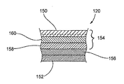
本開示は、以下の例によって、より具体的に記載することができるが、本開示はこれらの例に限定されない。これらの例の目的から、図1は、ラミネート102と射出成形部材104とを含む複合構造体の例示的な断片100を示す。図1Aに示されているように、ラミネート102は、基材106と、押出コーティング、押出ラミネート、フィルムラミネート、接着結合、熱結合、噴霧、ロールコーティング又は任意の他の化学的手段若しくは機械的手段又は他の適した方法によって基材106に塗布される1つ又は複数のコーティングすなわちフィルム108とを含むことができる。フィルム108は、例えば基材106の片面又は両面に塗布することができる。代替的には、ラミネート102は、複層の材料又は単層の材料とすることができる。ラミネートは任意選択的には、1つの層としてのマイクロ波相互作用部材及び/又は別の層に埋め込まれたマイクロ波相互作用部材を含むことができる。さらに、種々の材料及び/又は塗布方法を用いて、1つ又は複数の層を基材106の異なる面に形成することができるか、又は、1つ又は複数の材料層を基材106の一方の面に塗布し、他方の面には塗布しないこともできる。1つの例では、マイクロ波相互作用部材を基材106の一方の面に塗布することができ、防湿層を基材106の他方の面に塗布することができる。
Examples The present disclosure can be more specifically described by the following examples, but the present disclosure is not limited to these examples. For the purposes of these examples, FIG. 1 shows an
図1に示されているように、射出成形部材104は、強化繊維112を有するポリマー110(全体として:充填ポリマー114)を含むことができる。強化繊維112は、射出成形部材104を強化するために、及び/又は射出成形プロセス後の冷却時のポリマー110の収縮を低減するのに役立たせるために含めることができる。代替的には、強化繊維112は、射出成形部材104から省くことができる。射出成形部材104を金型内で成形することができ、その場合、ラミネート102を金型内で1つ又は複数のキャビティ及び/又はチャネルに隣接して位置決めして射出成形部材を成形する。
As shown in FIG. 1, the injection molded
複合構造体の断面100は、単なる一例として挙げられている。本開示は、ラミネート102及び射出成形構造体104の形状に限定されない。例えば、ラミネート102は、ブランクから成形されるトレイ、蓋、スリーブ及び/又は別の容器とすることができ、ブランクは、トレイ、蓋、スリーブ及び/又は別の容器、及び/又はプレス成形若しくはプリフォームしたトレイ、蓋、スリーブ及び/又は他の容器になるように成形されるためのものである。射出成形部材104は例えば、成形リム、成形スプライン及び/又は別の構造特徴部の一部とすることができる。さらに、ポリマー、天然繊維及び他の材料が単なる例として挙げられる。
The
実施例1
ラミネート102は、片面又は両面にセルロースフィルム108がラミネートされた板紙基材106を含む。射出成形部材104は、充填ポリマー114を形成するように天然繊維112を有する任意の適した生物由来のポリマー110、すなわち、部分的に生物由来のポリマーを含むことができる。1つ又は複数の適した接着促進処置をセルロースフィルム108に施すことができ、その場合、そのフィルムは、溶融した充填ポリマー114と接触して射出成形部材104をラミネート102に固定するのに役立つ。
Example 1
実施例2
ラミネート102は、板紙基材106と、完全に又は部分的に生物系のナイロン(例えば、ナイロン6又はナイロン6,6)層108とを含む。板紙基材106は、完全に若しくは部分的に生物系のナイロンで片面又は両面上にコーティングすることができるか、又は、完全に若しくは部分的に生物系のナイロンを例えばフィルムになるように形成して板紙基材106上にラミネートすることができる。射出成形部材104は、充填ポリマー114を形成するように天然繊維112が充填された完全に又は部分的に生物系のナイロン(例えば、ナイロン6又はナイロン6,6)110を含む。
Example 2
The laminate 102 includes a
実施例3
ラミネート102は、板紙基材106と、完全に又は部分的に生物系のポリエステル(例えば、PET)層108とを含む。板紙基材106は、完全に若しくは部分的に生物系のポリエステルで片面又は両面上にコーティングすることができるか、又は、完全に若しくは部分的に生物系のポリエステルを例えばフィルムになるように形成して板紙基材106上にラミネートすることができる。射出成形部材104は、天然繊維112が充填された完全に又は部分的に生物系のポリエステル110を含む。1つの例では、選択された完全に又は部分的に生物系のポリエステルは、華氏約200度を超える温度耐性を有することができる。
Example 3
The laminate 102 includes a
上記の例又は再生可能な材料を含む任意の代替的な複合構造体はいずれも、複合構造体の実質的に全体が適切な条件下で分解するように適した分解性特性を有する、完全に又は部分的に生物系のポリマーを組み入れることができる。例えば、ポリマーは、堆肥化条件で(例えば、熱及び水分を管理する産業システムにおいて、家庭内堆肥化システムにおいて)分解するように選択することができる。1つの実施形態では、複合構造体は、堆肥化の標準分解性試験を満たすポリマー及び他の材料を含む。 Any of the above examples or any alternative composite structures comprising renewable materials are fully destructible with suitable degradability characteristics such that substantially the entire composite structure degrades under appropriate conditions. Alternatively, partially biological polymers can be incorporated. For example, the polymer can be selected to degrade at composting conditions (eg, in an industrial system that manages heat and moisture, in a domestic composting system). In one embodiment, the composite structure includes polymers and other materials that meet the standard degradability test for composting.
1つの実施形態によれば、複合構造体は、最大100パーセント再生可能な供給源及び/又は最大100パーセント分解性の材料を由来とする材料をそれぞれが含む複数の部材を有する。したがって、複合構造体は、再生不能な資源に対する負担がほとんどあり得ないか又は全くあり得ず、再生可能な材料及び/又は分解性の材料の使用が消費者への宣伝となり得る。さらに、本開示は、複合構造体の利点、例えば、高い調理温度でのパッケージのグラフィック及びスチフネスの向上に紙又は板紙を使用する利点、及び、障壁及び漏れ防止(例えば、フィルム又はコーティングとして)並びに強化及び充填パッケージのシール性(例えば、射出成形スプライン及び/又は射出成形リム)にポリマーを使用する利点を有する、再生可能な材料及び/又は分解性の材料を構造体に使用することに関する。したがって、再生可能な複合構造体は、広範な考えら得る機能性を有することができ、同種の構造体よりも、更なる包装部材を必要とする傾向が低い。 According to one embodiment, the composite structure has a plurality of members each comprising a material derived from a source that is up to 100 percent renewable and / or a material that is up to 100 percent degradable. Thus, composite structures can have little or no burden on non-renewable resources, and the use of renewable and / or degradable materials can be an advertisement to consumers. Further, the present disclosure provides the advantages of composite structures, such as the benefits of using paper or paperboard to improve package graphics and stiffness at high cooking temperatures, and barriers and leak proofing (eg, as a film or coating) and It relates to the use of renewable and / or degradable materials for structures that have the advantage of using polymers for the sealing (eg, injection molded splines and / or injection molded rims) of reinforced and filled packages. Thus, renewable composite structures can have a wide range of conceivable functionalities and are less likely to require additional packaging members than similar structures.
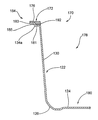
第1の例示的な実施形態では、図2は、構成体、すなわちブランク122を示し、ブランク122は、図3A及び図3Bに示されているラミネート120、120’等のラミネートを含むことができ、また、射出成形構造体172とともに成形されて、図4に示されているような複合構造体すなわちトレイ170にすることができる。第1の例示的な実施形態の複合構造体は、2012年2月28日に発行された米国特許第8,124,201号に図示及び記載されている複合構造体と類似している。上記米国特許の開示はその全体が、あたかも本明細書に提示されているかのように、あらゆる目的から、引用することにより本明細書の一部をなす。しかしながら、本開示のトレイ170は、ラミネート120、120’と、再生可能な材料及び/又は分解性の材料を含む射出成形構造体172とを有する。第1の例示的な実施形態の複合構造体は、単なる例として図示及び記載されている。本開示の複合構造体は、再生可能な材料を含む任意の適した複合構造体とすることができる。
In a first exemplary embodiment, FIG. 2 shows a construct, ie, blank 122, which can include a laminate such as the laminate 120, 120 ′ shown in FIGS. 3A and 3B. Alternatively, it can be molded with an injection molded
図2に示されているように、ブランク122は、内側折り線128によって中間パネル126につながっている底部パネル124を有する。中間パネル126はそれぞれ、側部パネル130につながっており、側部パネル130は、中間折り線132によって、フラップとして特徴付けることもできる。フランジ部分134a乃至134dがそれぞれ、外側折り線136によって側部パネル130につながっている。ブランク122はまた、コーナー間隙140を規定しており、これらのコーナー間隙140のそれぞれは、幾分V字状である。ブランク122は、本開示から逸脱することなく代替的な構成とすることができる。
As shown in FIG. 2, the blank 122 has a
図3Aを参照しながら最もよく理解されるように、ブランク122を形成することができるラミネート120は、2つ以上の層を含むが、代替的には、ラミネートの代わりに、板紙、ボール紙、紙、少なくとも部分的に生物由来の高分子シート、及び/又は別の再生可能な材料等であるがそれらに限定されない単層の材料を用いることができる。1つの実施形態では、ラミネート120、120’は、実施例において上述したラミネート102と同様又は同じとすることができる。第1の例示的な実施形態によれば、ラミネート120は、少なくとも部分的に生物由来のポリマーフィルム150を有し、このポリマーフィルム150は、ボール紙、板紙152又は任意の他の適した材料の形態とすることができる基材によって支持されるとともにその基材に固定される。代替的には、板紙152及び少なくとも部分的に生物由来のポリマーフィルム150の代わりに、例えば任意の他の適した再生可能な材料を用いることができ、そのため、本開示の基材は板紙等に限定されない。明らかであるべき通り、板紙152はより一般的には基材として特徴付けることができ、適した基材として、クレーコーティング、着色剤、インディシア等を含むことができるコーティング等の典型的な補足材料を有する又は有しない板紙を含むことができる。
As best understood with reference to FIG. 3A, the laminate 120 from which the blank 122 can be formed includes two or more layers, but alternatively, instead of a laminate, paperboard, cardboard, Single layer materials such as, but not limited to, paper, at least partially bio-derived polymer sheets, and / or other renewable materials can be used. In one embodiment, the laminate 120, 120 'can be similar or the same as the laminate 102 described above in the examples. According to a first exemplary embodiment, the laminate 120 has an at least partially
任意選択的には、図3Aに示されているように、少なくとも部分的に生物由来のポリマーフィルム150は、接着材料156の層によって板紙152に固定されているマイクロ波相互作用ウェブ154の一部とすることができる。ウェブ154は、1つ又は複数の層の接着材料160又は任意の他の適した手段によって少なくとも部分的に生物由来のポリマーフィルム150に固定される、1つ又は複数の層のマイクロ波エネルギー相互作用材料158を更に有することができる。マイクロ波エネルギー相互作用材料158をラミネート120内に組み入れて、ブランク122から形成されるとともにマイクロ波エネルギーに曝される容器(例えば、図4のトレイ170)が収容している食品の調理及び/又は加熱を高めるか又は別様に調節することができる。
Optionally, as shown in FIG. 3A, at least partially
少なくとも部分的に生物由来のポリマーフィルム150をウェブ154の一部であるものとして上述したが、少なくとも部分的に生物由来のポリマーフィルム150が接着材料156の層又は任意の他の許容可能な手段によって板紙154に直接接着されることも本開示の範囲内にあり、そのため、1つ又は複数の層のマイクロ波エネルギー相互作用材料158及び関連の接着材料156、160は省かれる。例えば、フィルム150は、板紙152上に直接押し出す(すなわち、押出コーティングプロセスによる)ことができる。さらに、フィルム150は、図3Aにフィルム150を分割するものとして示されている破線によって概略的に示されているように共押出フィルムとすることができる。異なる数の層を有するとともに特性が異なる層を有する多様な異なるタイプの共押出物が、本開示の範囲内にある。例えば、共押出物の種々の層が、酸素及び水分の透過を制限することに関する特性に限定されないがそれらのような広く多様な異なる特性を示すことができる。同様に、種々のマーキング(例えば、絵及び/又は文字)及び/又は色を、フィルム150、若しくはブランク122の任意の他の部分、若しくはトレイ170に組み入れるか、又は、フィルム150、若しくはブランク122の任意の他の部分、若しくはトレイ170上に付着させることができる。
Although the at least partially
マイクロ波エネルギー相互作用材料158が省かれる場合、ブランク122から形成される複合構造体(例えば、図4のトレイ170)はマイクロ波エネルギーに対して透過性があることができる。それにもかかわらず、マイクロ波エネルギーに対して透過性があるそのような容器は、依然として電子レンジにおいて使用することができ、従来のオーブンにおいて使用することもできる。ブランク122から形成される容器が従来のオーブンにおいて高温で使用される場合、複合構造体を形成する再生可能な材料(例えば、ブランク122を形成する材料)をそれらの材料が高温に十分に耐えるように選択することができる。
If the microwave energy
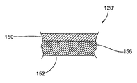
上記から明らかであるべき通り、ブランク122を形成することができる広く多様なラミネートが、本開示の範囲内にある。例えば、上述したように、かつ図3Bに示されているように、ブランク122を形成することができるラミネート120’は、間に位置決めされるとともに、少なくとも部分的に生物由来のポリマーフィルム150(1つ又は複数の層のポリマーフィルム等の形態とすることができる)を基材(例えば、板紙)152に(間接的又は直接的に)接合する接着材料156の層を有することができる。マイクロ波エネルギー相互作用材料158は任意選択的には、少なくとも部分的に生物由来のポリマーフィルム150と関連付けることができる。
As should be apparent from the above, a wide variety of laminates capable of forming the blank 122 are within the scope of the present disclosure. For example, as described above and as shown in FIG. 3B, the laminate 120 ′ from which the blank 122 can be formed is positioned between and at least partially biopolymer film 150 (1 There may be a layer of
実質的に任意のマイクロ波エネルギー相互作用材料158は、ブランク122が形成される前にラミネート120の一部とすることができるか、又は、ブランク122が形成された後にブランク122に固定することができる。代替的には、マイクロ波相互作用ウェブ154及び/又はマイクロ波相互作用材料158は、既に起立させた複合構造体(例えば、トレイ170)に施されるか又は別様に取り付けることができる。1つの特定の例として、マイクロ波相互作用ウェブを、先に成形したトレイ170の内面に(例えば、接着材料、熱シールコーティング又は任意の他の適した手段によって)取り付けることができる。
Substantially any microwave energy
接着材料156は、少なくとも部分的に生物由来のポリマーフィルム150及び/又はウェブ154が意図せずに不所望な時点で板紙152から分離しないように十分に強力な剥離強度を提供するように選択及び塗布することができる。例示的な実施形態の1つの許容可能な方法に従って、使用者が複合構造体(例えば、トレイ170)を使用し終えるまで、少なくとも部分的に生物由来のポリマーフィルム150及び/又はウェブ154が板紙152から分離しないことが望ましい。1つの例では、接着材料156は、材料の分解に役立たせるために、及び/又は板紙152を容易に分離して再利用することができるように、可溶性接着剤(例えば、水溶性接着剤)及び/又は可剥性接着剤とすることができる。
The
ラミネート120、120’を形成する許容可能な方法の特定の数例を上述したが、当業者であれば、ラミネートを構成することができる多様な方法があることを理解するであろう。すなわち、ラミネート120、120’の層は、任意の適したプロセス又は技法を用いて接合することができる。限定ではなく例として、層は、接着結合、熱結合又は任意の他の化学的手段若しくは機械的手段を用いて接合することができる。結合は、任意の適したプロセス、例えば、噴霧、ロールコーティング、押出ラミネート又は任意の他のプロセスを用いて達成することができる。 While several specific examples of acceptable methods of forming the laminate 120, 120 'have been described above, those skilled in the art will appreciate that there are a variety of ways in which the laminate can be constructed. That is, the layers of the laminate 120, 120 'can be joined using any suitable process or technique. By way of example and not limitation, the layers can be joined using adhesive bonding, thermal bonding, or any other chemical or mechanical means. Bonding can be accomplished using any suitable process, such as spraying, roll coating, extrusion lamination, or any other process.
第1の例示的な実施形態によれば、トレイ170は、少なくとも実質的に漏れ防止性があり、及び/又は密封される。したがって、折り線128、132、136のそれぞれは、ブランク122に穴を形成しないスコア線であることが一般的である。本開示の代替的な実施形態によれば、折り線128、132、136は、任意の従来の様式で形成することができ、ひと続きであるか、分断されているか又は部分的であるものとすることができ、それらの折り線のうちの1つ又は複数は省くことができる。
According to the first exemplary embodiment, the
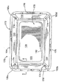
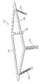
図4を参照しながら最もよく理解されるように、第1の実施形態のトレイ170は、ブランク122と、ブランクを起立構成に保持する射出成形部材すなわちフレーム172とを有する。フレーム172は、少なくとも部分的に生物由来の高分子材料から構成することができるが、他のタイプの再生可能な材料から構成することもできる。フレーム172を単独で概略的に示す図5も参照すると、フレーム172は、フレーム172の実質的に剛性のリム又はバンド176から(斜めに、又はより具体的には鋭角に)下方にかつ幾分内側に延びるスプライン又はストリップ状のコーナー部材174を有する。第1の実施形態によれば、コーナー部材174はトレイ170のコーナーを密封することが有利である。
As best understood with reference to FIG. 4, the
図4を参照しながら最もよく理解されるように、ブランク122のパネル124、130、126(図2)及びフレーム172のストリップ状のコーナー部材174はともに、トレイ170の実質的に漏れ防止性の空洞178の周囲に延びるとともにその空洞を画定する。概して、ブランクの少なくとも部分的に生物由来のポリマーフィルム150(図3A及び図3B)は、流体不透過性であり、空洞178と対面する。トレイ170の底部パネル124は任意選択的には、エンボス加工エリア180を有し、このエリア180は、底部パネル124内にスコア状の線182によって部分的に画定されている。底部パネル124のエンボス加工エリア180は、トレイ170の空洞178に僅かに突出しており、トレイをより剛性にするのに役立つことができる。
As best understood with reference to FIG. 4, the
図6は、断面のみが示されている、図4の6−6の線に沿った、トレイ170の概略断面図である。トレイ170は多段リム184を有することができる。リム184は、トレイ170の空洞178に対する開口の周囲に延びるとともにその開口を画定する。リム184の上部は、フレーム172のバンド176によって画定することができ、リム184の下部は、ブランク122のフランジ部分134a乃至134dによって画定することができる。図6に示されているように、リム184の2つの段は、ブランクのフランジ部分134a乃至134dのそれぞれの直立パネル又は直立セクション185によって部分的に画定される。下側フランジ181が、それぞれの側部パネル130の上縁から直立セクション185の下縁まで外方に延びる。上側フランジ183が、直立パネル又は直立セクション185の上縁から外方に延びる。上側フランジ183の全体又は一部は省くことができる。各直立セクション185は、直立内方肩部192を有する。バンド176は、フランジ181、183の上面及び内方肩部192に接着することができ、そのため、フランジ181、183の上面よりも上に位置決めされる平坦な上面を有し、カバー、蓋等をバンドの上面にシールすることができる。バンド176は、上側フランジ183の上よりも下側フランジ181の上をより厚くすることができ、そのため、下側フランジは、射出成形時に内部に成形材料(例えば、流体高分子材料)を流すための比較的大きなチャネルを部分的に画定することが有利である。
6 is a schematic cross-sectional view of the
図6は、トレイ170の複数の部分の縦断面の例示である。より具体的には、図6は、側部パネル130のそれぞれと多段リム184の関連部分とに沿った縦断面の例示及び/又は代表図である。その一方では、他の断面プロファイルも本開示の範囲内にある。例えば、ブランクのフランジ部分134a乃至134dは、トレイ170のリム184の外縁まで延びないように又はフレーム172のバンド176内に埋め込まれるように異なる方法で形状決め及び/又はサイズ決めすることができる。別の例として、ブランク122のフランジ部分134a乃至134d等は、フレーム172のバンド176よりも更に外方に延びることができる。
FIG. 6 is an example of a longitudinal section of a plurality of portions of the
1つの実施形態では、トレイ170は、バンド176と同様であるが下側フランジ181よりも下に位置付けられているとともに第1の領域及び第2の領域を有するバンドを備えることができ、その場合、第1の領域は、側部パネル130と下側フランジ181の少なくとも一部とに接触し、第2の領域は、第1の領域から側方外側に延びる。1つの代替的な実施形態では、第1の領域は、2007年4月18日に出願された米国特許出願公開第2007/0194029号に開示されているような第2の領域よりも大きい断面積を有する。上記米国特許出願公開は、あらゆる目的から、引用することにより本明細書の一部をなす。さらに、バンド176又は他の代替形態を、本開示から逸脱することなく、コーナー部材174を有しないトレイ170のリムの周囲に位置付けることができる。
In one embodiment, the
トレイ170を製造する例示的な方法と関連付けられる幾つかの態様が、図4に示されている。フレーム172は、金型に射出される成形材料、すなわち、少なくとも部分的に生物由来の高分子材料から製造することができる。すなわち、液体成形材料が(例えば、バルブゲートを介して)射出される。図4のフレーム172上に描かれている矢印は、流体成形材料の一部がフレーム172を形成するように流れることができる方向を概略的に示す。図4のフレーム172上に描かれている矢印は図式的であり、形成されたトレイ170上に見られることはない。
Several aspects associated with an exemplary method of
第1の例示的な実施形態によれば、図6を参照すると、流体成形材料の流れは、ブランク122のフランジ部分134a乃至134dの上部にフレーム172のバンド176を保持するようにして制御される。より具体的には、フランジ部分134a乃至134d(図2)の端縁はそれぞれ重なり合い、フランジ部分の少なくとも一部は任意選択的には、射出成形時に流体成形材料がフランジ部分134a乃至134dの上を流れるようにピンによって所定の様式で保持される。さらにより具体的には、図2及び図4を参照することによって最もよく理解されるように、フランジ部分134a乃至134dはそれぞれ、重なり合う端縁190a、190b、190c、190d(図4ではバンド176によって視界から隠れており、したがって、図4では破線で示されている)を有する。図4に示されているトレイ170では、フランジ部分134aの端縁190aがフランジ部分134bの隣接端と重なり合い、そのため、フランジ部分134bの端縁がフランジ部分134aの下にある。同様に、フランジ部分134aの端縁190bが、フランジ部分134cの隣接端に重なる。同様に、フランジ部分134bの端縁190cが、フランジ部分134dの隣接端に重なる。最後に、フランジ部分134cの端縁190dが、フランジ部分134dの隣接端に重なる。これらの重なり合う縁は、省くことができるか、又は、本開示から逸脱することなく別様に構成することができる。
According to a first exemplary embodiment, referring to FIG. 6, the flow of fluid molding material is controlled to hold the
本開示の他の実施形態によれば、種々の技法を用いて、ブランク122のフランジ部分134a乃至134dの上部にフレーム172のバンド176を形成することができる。1つの例として、重なり合う端縁190a乃至190dのピン留めは省くことができ、フレーム172は、金型組立体の複数の位置において主キャビティに流体成形材料を射出することによって成形することができる。対照的に、本開示の他の代替的な実施形態によれば、フレームのバンド176は、ブランク122のフランジ部分134a乃至134dの上部に成形されない。例えば、フランジ部分134a乃至134dは、バンド176内に埋め込むことができるか、又は、バンドの上に位置決めすることができる。
According to other embodiments of the present disclosure, the
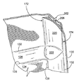
図7は、トレイ170の上部が切り欠かれているとともにフレーム172のストリップ状のコーナー部材174の更なる上部が切り欠かれている、トレイ170のそれぞれのコーナーの内側を示す。フレーム172のストリップ状のコーナー部材174は、トレイ170のコーナーに沿って延びるとともにそのコーナーを少なくとも部分的に画定するストリップであること又はそのようなストリップを有するものとして特徴付けることができ、このストリップが比較的小さい間隙202を塞ぐ。間隙202は、側部パネル130の、コーナーを部分的に画定している縁間に画定することができる。代替的には、側部パネル130は、少なくとも部分的に重なり合うことができ、そのため、間隙202は省かれる。コーナーの外側の大部分は、ブランク122の板紙152、又はラミネート120、120’、102のうちの1つ又は複数の別の部分によって規定されるが、ただし、フレーム172の関連付けられたストリップ状のコーナー部材174のビード206(例えば、細長い外方に突出する突起)が間隙202に突出するとともに間隙202を塞ぐ(例えば、密封する)。異なる方法で構成されるコーナー及びリムは、本開示の範囲内にある。
FIG. 7 shows the inside of each corner of the
図4及び図7に示されているように、トレイ170の各内側コーナーに関して、コーナーの内側は、上から下にかけて左右に滑らかに丸みがある。フレーム172の、コーナーに延びるストリップ状のコーナー部材174は、上側部分220及び下側部分222を有するものとして特徴付けることができる内向きの滑らかな表面を有する。コーナー部材174は、トレイ170のコーナーの内側の滑らかな左右の湾曲に関与するように形状決めされる。より具体的には、(ストリップ状のコーナー部材174の内向き面の)上側部分220は、隣接する側部パネル130間に凹状かつ滑らかにリム184まで延びる。(コーナー部材174の内向き面の)下側部分222は、隣接する中間パネル126間に滑らかにかつ幾分凹状及び/又は椀状に延びる。
As shown in FIGS. 4 and 7, for each inner corner of the
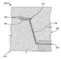
第1の例示的な実施形態によれば、図8は、ブランク122と少なくとも部分的に生物由来のポリマーとからトレイ170を成形する成形工具すなわち金型組立体230の一部を示す。例えば、ブランク122は、雌型234に対して位置決め及び/又は固定することができ、雌型234及び雄型232は、ブランク122が雌型234と雄型232との間に挟まれるようにともに合わさることができる。金型組立体230が更に閉じるにつれ、ブランク122と金型組立体230との相互作用により、ブランクの折り線128、132、136に沿って折り曲げが生じ、それによって、ブランクが起立される。結果として、ブランク122は、金型組立体230が図8に部分的に概略的に示されている完全に閉じた構成を達成すると、金型組立体の主キャビティ内で起立状態にある。成形材料を受け取るチャネルが、少なくとも起立されたブランク122と雄型232との間に形成される。チャネルは、フレーム172の形状に少なくとも概ね対応する。より具体的には、例えば、流体成形材料(例えば、少なくとも部分的に生物由来の流体高分子材料)を圧力下で初期チャネルへと押し流すにつれ、流体成形材料がチャネル内に流れる間、ブランク122のそれぞれの部分の位置変化に起因して、初期チャネルの少なくとも一部が拡張して変形することで最終的なチャネルとなる。これは、ブランク122の幾つかの部分を雌型234の各表面に押し付けるのに十分な力を伴って液体成形材料を流すことを伴う。
According to a first exemplary embodiment, FIG. 8 illustrates a portion of a forming tool or
1つの例では、液体成形材料は、閉じた金型組立体230に射出される少なくとも部分的に生物由来のポリマーであり、この射出ポリマーは、温度が華氏約500度、圧力がおよそ2000lb/in2である。射出温度及び射出圧力は、射出される少なくとも部分的に生物由来のポリマーに応じて決まることができ、広く多様な少なくとも部分的に生物由来のポリマー、温度及び圧力が本開示の範囲内にある。例えば、本開示の範囲を限定する目的ではなく、射出するのに適した少なくとも部分的に生物由来のポリマーは、少なくとも部分的に生物由来のポリプロピレン、少なくとも部分的に生物由来のナイロン及び少なくとも部分的に生物由来のポリエチレンテレフタレート(PET)とすることができる。閉じた金型組立体230に射出される高分子液体成形材料は、短天然繊維等の1つ又は複数の添加物を有することができる。例えば、短天然繊維として、約1ミリメートル乃至約100ミリメートルの平均長さ、すなわち、平均長さ対直径の比が約5:1乃至約100:1の天然繊維を挙げることができる。しかしながら、本開示から逸脱することなく任意の適した繊維長を用いることができる。少なくとも部分的に生物由来の高分子液体成形材料に短天然繊維を含浸することにより、固化する少なくとも部分的に生物由来の高分子材料の収縮を有利に制御及び/又は最小限に抑えることに役立たせることができる。少なくとも部分的に生物由来の高分子液体成形材料は、約30重量%の天然繊維を含むことができるが、他の量及び他の添加物も本開示の範囲内にある。
In one example, the liquid molding material is an at least partially biological polymer that is injected into the
液体成形材料が固化し、それによってトレイ170が金型組立体230内で成形された後、金型組立体を型開きすることができ、トレイ170を離型することができる。
After the liquid molding material has solidified and thereby the
第1の実施形態によれば、トレイ170を構成する、ラミネート120のフィルム150と、成形材料(例えば、少なくとも部分的に生物由来の高分子材料)とは、フレーム172とブランク122のフィルム150との間に優れた接着がもたらされるよう、適合性があるように選択される。1つの例では、フレーム172及びフィルム150は双方とも、少なくとも部分的に生物由来のナイロン又はポリエチレンテレフタレートである。広く多様な他の少なくとも部分的に生物由来のポリマーを使用することもできる。フィルム150が共押出物である際、フィルム150とフレーム172との間に優れた接着がもたらされるよう、少なくともフィルム150の最外層がフレーム172と適合性があるように選択される。代替的な実施形態では、それらの間にあまり接着がもたらされない(すなわち、フレーム172とブランク122との間にあまり接着がもたらされない)ように材料が選択される場合等、そのブランク又はそのブランクの部分(例えば、ブランクの縁)は、それでもなお、所望であればブランク及びフレームが互いにしっかりと付着するようにしてフレーム内に少なくとも部分的に埋め込まれるか又はフレームによって被包することができる。
According to the first embodiment, the
スコア線とすることができる折り線128、132、136を有するブランク122を初めに成形することにより、閉じている金型組立体230内でのブランクの起立に役立つようにする。しかしながら、1つ又は複数のスコア線(例えば、折り線128、132、136)は、ブランク122から省くことができ、この場合、ブランクが内部で適正に起立されることを確実にするには、金型組立体を比較的ゆっくりと閉じることが必要であり得る。多様な異なるブランクが本開示の範囲内にある。同様に、多様な異なる金型組立体が本開示の範囲内にある。したがって、多様な異なる複合構造体(例えば、ブランク、トレイ、カートン、スリーブ及び他の容器)もまた、本開示の範囲内にある。
The blank 122 having the
第1の実施形態に従って、トレイ170が成形された後、食品をトレイの空洞178内に載置することができ、次に、フレーム172のバンド176の平坦な上面にヒートシールすることができることが有利である蓋用フィルム又は高分子ラップの形態のカバー等によって、トレイの開口を漏れ防止式に閉じることができる。例えば、図9は、食品270を収容しているとともに、フレーム172のバンド176の実質的に平坦な上向き面にヒートシールされているポリマーフィルム272によって閉じられている、図4のトレイ170を概略的に示す。図9は、視界から隠れている食品270が破線によって示されており、また、トレイ170を閉じているポリマーフィルム272の厚さが誇張されているため、概略的である。ポリマーフィルム272は、少なくとも部分的に生物由来のポリマー又は任意の適した再生可能な材料若しくは分解性の材料を含むことができる。代替的には、トレイ170は、上記の例において記載したラミネート102と同様又は同じラミネート、板紙、箔又は任意の他の適した材料から作製される蓋によって閉じることができる。漏れ防止式等にトレイ170の開口を閉じる多様な機構が本開示の範囲内にある。
In accordance with the first embodiment, after the
第1の例示的な実施形態では、トレイ170は、ブランク122から形成され、リム176及びスプライン174を有するフレーム172を有する。図10に例として示されている第2の例示的な実施形態によれば、複合構造体(例えば、容器302)は、プリフォームされ、成形され、及び/又はプレス成形されることができる。代替的には、容器302は、本開示の1つの例示的な実施形態に従って、概ね平坦なブランク(不図示)から形成することができる。第2の例示的な実施形態の容器302は、スプラインを有しない、容器302のリムの一部を形成する射出成形構造体338を有することができる。代替的には、射出成形構造体338は、容器302をシール及び/又は強化するのに役立つスプラインを有することができる。第2の例示的な実施形態の複合構造体は、2011年7月12日に発行された米国特許第7,975,871号に図示及び記載されている複合構造体と類似している。上記米国特許の開示はその全体が、あたかも本明細書に提示されているかのように、あらゆる目的から、引用することにより本明細書の一部をなす。しかしながら、本開示の容器302は、再生可能な材料及び/又は分解性の材料を含む。第2の例示的な実施形態の複合構造体が単なる例として図示及び記載されている。本開示の複合構造体は、再生可能な材料を含む任意の適した複合構造体とすることができる。
In the first exemplary embodiment, the
図10に示されているように、容器302は、底部パネル324と、底部パネル324に対して概ね上方に延びる2つの側部パネル326と、底部パネル324に対して概ね上方に延びる2つの端部パネル330とを有する。図示の実施形態では、容器302は概して、開口上部305(図12)と、側部パネル326と端部パネル330とのそれぞれの接合部における4つの丸コーナー304とを有するトレイである。底部パネル324、側部パネル326、端部パネル330、及び丸コーナー304は、食品又は他の物質を収容する空洞309(図12)を形成する。容器302は、側部パネル326の上縁、端部パネル330の上縁及びコーナー304の上縁に形成されるフランジ336を有することができる。フランジ336は、側部パネル326の上縁、端部パネル330の上縁、及びコーナー304の上縁から側方外側に延びて容器の頂縁を形成する。
As shown in FIG. 10, the
図示の実施形態では、容器302とその内部に形成されている空洞309(図12)とは概ね矩形である。容器302は、本開示から逸脱することなく他の形状(例えば、円形)とすることができる。さらに、図示の実施形態のコーナー304は、容器302の成形時にプレス成形することができる成形コーナーである。容器302は、別様に成形されるコーナーを有することができる。
In the illustrated embodiment, the
1つの実施形態では、図11及び図12に示されているように、容器302は、フランジ336の下側で容器の外縁の周囲に延びる射出成形構造体338を有する。構造体338は、少なくとも部分的に生物由来の高分子材料から概ね構成されるが、他のタイプの再生可能な材料及び/又は分解性の材料から構成することもできる。図示の実施形態では、構造体338は、容器302の外縁の周囲に延び、容器の剛性を高めるのに役立つ。図12に示されているように、構造体338は、側部パネル326の上縁及び端部パネル330の上縁に隣接して概ね配置され、それらの上縁から側方外側に延びる。図示の実施形態では、構造体338は、射出成形構造体338の側縁343に対して側方外側に延びる。構造体338の側縁343は、フランジ336の側縁344と概ね合致する。他の実施形態では、射出成形構造体338の遠位部は、フランジ336の縁344を越えて側方外側に延びることができるか、又は、フランジが射出成形構造体338の縁を越えて延びるようにフランジの自由縁の側方内側の或る場所に部分的に延びることができる。別の実施形態では、射出成形構造体338は、フランジ336の下側の少なくとも一部、フランジの上側の少なくとも一部、及び/又はフランジの縁344の少なくとも一部に沿って延びることができる。1つの実施形態では、射出成形構造体338は、フランジ336の上部の一部、フランジの底部及びフランジの縁に沿って延びるように、フランジを少なくとも部分的に被包することができる。
In one embodiment, as shown in FIGS. 11 and 12, the
容器302は、2つ以上の層を有するラミネートから形成することができるが、代替的には、ラミネートは、板紙、ボール紙、紙又は少なくとも部分的に生物由来の高分子シート等であるがそれらに限定されない単層の材料とすることができる。本開示の例示的な実施形態に従って、ラミネートは、ボール紙、板紙又は任意の他の適した材料の形態とすることができる基材によって支持されるとともにそのような基材に固定される少なくとも部分的に生物由来のポリマーフィルム又は押出成形された少なくとも部分的に生物由来のポリマーコーティングを有することができる。代替的には、板紙及び少なくとも部分的に生物由来のポリマーフィルムの代わりに、任意の他の適した材料を用いることができ、そのため、例えば、本開示の基材は板紙等に限定されない。明らかであるべき通り、板紙はより一般的には、基材として特徴付けることができ、適した基材は、クレーコーティング、着色剤、インディシア等を含むことができるコーティング等の一般的な補助材料を有する又は有しない板紙を含むことができる。さらに、容器302は、第1の例示的な実施形態のブランク122に対して上述した材料のような他の材料、ラミネート、基材等を含むことができる。容器302は任意選択的には、マイクロ波エネルギー相互作用材料を含むことができる。
The
トレイ170及び容器302は、本開示の複合構造体の2つの例である。例えば、他の複合構造体が、少なくとも、2010年6月24日に出願された米国特許出願公開第2010/0308064号、2010年6月24日に出願された米国特許出願公開第2010/0314801号、及び2010年7月20日に出願された米国特許出願公開第2011/0012291号に図示及び記載されている。これらの米国特許出願公開の開示はその全体が、あたかも本明細書に提示されているかのように、あらゆる目的から、引用することにより本明細書の一部をなす。しかしながら、複合構造体は、食品又は他の製品を保持する等に用いる実質的に任意の構造体(例えば、容器、スリーブ又は他の構造体)とすることができ、再生可能な材料及び/又は分解性の材料を含む複数の部材(例えば、ラミネート及び射出成形部材)を有する。
天然繊維、再生可能なポリマー、及びそれらの複合体の幾つかの例が、2007年9月21日に出願された米国特許出願公開第2009/0236063号、2009年5月21日に出願された米国特許出願公開第2010/0029809号、2009年12月9日に出願された米国特許出願公開第2010/0144932号、2009年8月21日に出願された米国特許出願公開第2010/0266792号、2010年8月27日に出願された米国特許出願公開第2010/0320637号、Kalia, Susheel他著の「Pretreatments of Natural Fibers and their Application as Reinforcing Material in Polymer Composites-a Review」(Polymer Engineering and Science、2009年7月1日)、カナダ王立軍事大学の理工学部に提出された論文である、A.S. Fotso Talla著の「Design of a Hemp-Reinforced PET Composite I-Beam」(2008年11月)(発行者:Ottawa: Library and Archives Canada [2010])、Saira Taj他著の「Natural Fiber-Reinforced Polymer Composites」(2007年3月)(Proceedings of the Pakistan Academy of Science 44 (2): 129-144. 2007)、及び、S.V. Joshi他(ミシガン州立大学)著の「Are Natural Fiber Composites Environmentally Superior to Glass Fiber Reinforced Composites?」(Composites: Part A: Applied Science and Manufacturing 35 (2004), 371-376)に記載されている。上記の米国特許出願公開及び論文の開示はその全体が、あたかも本明細書に提示されているかのように、あらゆる目的から、引用することにより本明細書の一部をなす。上記の開示に挙げられている再生可能な材料及び天然繊維は、単なる例として挙げられており、本開示はそれらの材料に限定されないものとする。 Some examples of natural fibers, renewable polymers, and composites thereof have been filed on U.S. Patent Application Publication No. 2009/0236063, filed on May 21, 2009, filed on September 21, 2007. U.S. Patent Application Publication No. 2010/0029809, U.S. Patent Application Publication No. 2010/0144932 filed on Dec. 9, 2009, U.S. Patent Application Publication No. 2010/0266792 filed on Aug. 21, 2009, US Patent Application Publication No. 2010/0320637, filed August 27, 2010, Kalia, Susheel et al., “Pretreatments of Natural Fibers and their Application as Reinforcing Material in Polymer Composites-a Review” (Polymer Engineering and Science, July 1, 2009) AS Fotso Talla's “Design of Design”, a paper submitted to the Faculty of Science and Engineering at the Royal Military University of Canada. a Hemp-Reinforced PET Composite I-Beam (November 2008) (Publisher: Ottawa: Library and Archives Canada [2010]), Saira Taj et al., “Natural Fiber-Reinforced Polymer Composites” (March 2007) (Proceedings of the Pakistan Academy of Science 44 (2): 129-144. 2007) and “Are Natural Fiber Composites Environmentally Superior to Glass Fiber Reinforced Composites?” By SV Joshi et al. (Michigan State University) (Composites: Part A: Applied Science and Manufacturing 35 (2004), 371-376). The foregoing US patent application publications and paper disclosures are hereby incorporated by reference in their entirety for all purposes as if presented herein. The renewable materials and natural fibers listed in the above disclosure are given by way of example only and the present disclosure is not limited to those materials.
堆肥化可能な概ね同種の容器(例えば、容器は包括的には、単純な材料、すなわち、流体層でコーティング又はラミネートされた構造層を有する)の一例が、2009年8月19日に出願された米国特許出願公開第2010/0044267号に記載されている。この米国特許出願の開示はその全体が、あたかも本明細書に提示されているかのように、あらゆる目的から、引用することにより本明細書の一部をなす。本開示による複合構造体は、1つの例では複合構造体の1つ又は複数の部材と同様又は同じ材料を含むことができる。 An example of a generally compostable container (eg, the container generally has a simple material, ie, a structural layer coated or laminated with a fluid layer), filed on August 19, 2009. U.S. Patent Application Publication No. 2010/0044267. The disclosure of this US patent application is hereby incorporated by reference in its entirety for all purposes, as if presented herein. A composite structure according to the present disclosure may include the same or the same material as one or more members of the composite structure in one example.
本開示の種々の構造体はいずれも、任意選択的には、構造体に関連する食品の加熱又は調理時のマイクロ波エネルギーの効果を変える1つ又は複数の機能部を有していてもよい。例えば、構造体は、1つ又は複数のマイクロ波エネルギー相互作用部材(以下、「マイクロ波相互作用部材」と呼ぶこともある)から少なくとも部分的に成形することができ、このマイクロ波エネルギー相互作用部材は、食品の特定の領域をキツネ色及び/又はカリカリにすることを促すか、食品の特定の領域をマイクロ波エネルギーから遮蔽してその過調理を防止するか、又は、マイクロ波エネルギーを食品の特定の領域に対して接離させる。各マイクロ波相互作用部材は、特定の構造体及び食品の必要又は所望に応じて、マイクロ波エネルギーを吸収するか、マイクロ波エネルギーを伝達するか、マイクロ波エネルギーを反射させるか又はマイクロ波エネルギーを方向付ける特定の構成で配置される1つ又は複数のマイクロ波エネルギー相互作用材料又はマイクロ波エネルギー相互作用セグメントを含む。 Any of the various structures of the present disclosure may optionally have one or more features that alter the effect of microwave energy when heating or cooking food associated with the structure. . For example, the structure can be shaped at least in part from one or more microwave energy interactive members (hereinafter sometimes referred to as “microwave interactive members”). The member encourages certain areas of the food to be fox-colored and / or crispy, shields certain areas of the food from microwave energy to prevent overcooking, or microwave energy to the food It is made to approach and separate from a specific area. Each microwave interaction member may absorb microwave energy, transmit microwave energy, reflect microwave energy, or reflect microwave energy as required or desired for a particular structure and food. It includes one or more microwave energy interactive materials or microwave energy interactive segments arranged in a specific configuration to direct.
マイクロ波相互作用部材は、マイクロ波相互作用材料と食品との接触を操作しやすくする及び/又はその接触を防止するためにマイクロ波不活性基材又はマイクロ波透過基材上に支持され得る。便宜上かつ限定しないものとして、マイクロ波透過基材上に支持されるマイクロ波相互作用部材は、マイクロ波相互作用部材又はマイクロ波相互作用成分及びマイクロ波不活性部材又はマイクロ波不活性成分の双方を含むことが理解されるが、そのような構造体は、本明細書では「マイクロ波相互作用ウェブ」と呼ばれる。 The microwave interactive member may be supported on a microwave inert substrate or a microwave transmissive substrate to facilitate and / or prevent contact between the microwave interactive material and the food product. For convenience and non-limitation, the microwave interaction member supported on the microwave transparent substrate comprises both a microwave interaction member or microwave interaction component and a microwave inactive member or microwave inactive component. It is understood that such a structure is referred to herein as a “microwave interaction web”.
1つの例では、マイクロ波相互作用部材は、薄層のマイクロ波相互作用材料を含むことができ、このマイクロ波相互作用材料はマイクロ波エネルギーを吸収し、それによって食品との界面において熱を発生させる傾向がある。そのような部材は多くの場合、食品の表面をキツネ色及び/又はカリカリにすることを促すのに用いられる(「キツネ色及び/又はカリカリにする部材」と呼ぶこともある)。そのような部材は、フィルム又は他の基材上に支持される場合、「サセプターフィルム」又は単に「サセプター」と呼ぶことができる。しかしながら、他のマイクロ波エネルギー相互作用部材が本開示に含まれる。 In one example, the microwave interaction member can include a thin layer of microwave interaction material that absorbs microwave energy and thereby generates heat at the food interface. There is a tendency to make it. Such members are often used to promote the fox and / or crispy surface of the food (sometimes referred to as “fox and / or crunchy”). Such a member, when supported on a film or other substrate, can be referred to as a “susceptor film” or simply a “susceptor”. However, other microwave energy interactive members are included in the present disclosure.
別例として、マイクロ波相互作用部材は、食品の1つ又は複数の選択された部分をマイクロ波エネルギーから遮蔽するのに十分な厚さを有する箔(「遮蔽部材」と呼ぶこともある)を含むことができる。そのような遮蔽部材は、加熱時に食品が焦げやすいか又は乾燥しきってしまいやすい場合に用いられ得る。 As another example, the microwave interaction member may be a foil (sometimes referred to as a “shielding member”) having a thickness sufficient to shield one or more selected portions of the food from microwave energy. Can be included. Such a shielding member can be used when the food is easily burned or dried up during heating.
更に別の例として、マイクロ波相互作用部材はセグメント箔を含み得る。セグメント箔はひと続きでないが、そのようなセグメントの適切に離間した群は多くの場合、マイクロ波エネルギーを食品の特定の領域に方向付ける伝達部材として作用する。そのような箔は、キツネ色及び/又はカリカリにする部材、例えばサセプターと組み合わせて用いることもできる。 As yet another example, the microwave interactive member may include a segment foil. Although segment foils are not continuous, appropriately spaced groups of such segments often act as transmission members that direct microwave energy to specific areas of the food product. Such foils can also be used in combination with a fox and / or crunchy member, such as a susceptor.
上述したように、上記部材、及び本明細書において意図される多数の他の部材はいずれも、基材上に支持され得る。基材は、絶縁体、例えば、ポリマーフィルム又は高分子材料を含むことができる。概して、本明細書において用いられている場合、「ポリマー」又は「高分子材料」という用語は、例えば、ホモポリマー、ブロックコポリマー、グラフトコポリマー、ランダムコポリマー、及び交互コポリマーのようなコポリマー、ターポリマー等、並びにそれらのブレンド及び変性体を含むがそれらに限定されない。さらに、別様に具体的に限定されない限り、「ポリマー」という用語は、分子のあり得る全ての幾何学的な形態を含むものとする。これらの形態として、アイソタクチックシンメトリ、シンジオタクチックシンメトリ及びランダムシンメトリが挙げられるがそれらに限定されない。紙及び紙ラミネート、金属酸化物、ケイ酸塩、セルロース化合物、又はそれらの任意の組合せ等の他の基材材料も使用することができる。 As noted above, any of the above members, and many other members contemplated herein, can be supported on a substrate. The substrate can include an insulator, such as a polymer film or a polymeric material. In general, as used herein, the term “polymer” or “polymeric material” refers to copolymers, terpolymers, etc., such as homopolymers, block copolymers, graft copolymers, random copolymers, and alternating copolymers, for example. And blends and modifications thereof, but are not limited thereto. Further, unless otherwise specifically limited, the term “polymer” is intended to include all possible geometric forms of the molecule. These forms include, but are not limited to, isotactic symmetry, syndiotactic symmetry, and random symmetry. Other substrate materials such as paper and paper laminates, metal oxides, silicates, cellulose compounds, or any combination thereof can also be used.
マイクロ波エネルギー相互作用材料は、任意の適した様式で基材に塗布することができ、幾つかの例では、マイクロ波エネルギー相互作用材料は、基材上に印刷、押出、スパッタリング、蒸着、又はラミネートされる。マイクロ波エネルギー相互作用材料を、任意のパターンで任意の技法を用いて基材に施して、食品の所望の加熱効果を達成することができる。マイクロ波エネルギー相互作用材料のパターンの特定の例を本明細書において図示及び記載しているが、マイクロ波エネルギー相互作用材料の他のパターン及びタイプが本開示によって意図されることを理解すべきである。 The microwave energy interactive material can be applied to the substrate in any suitable manner, and in some examples, the microwave energy interactive material can be printed, extruded, sputtered, deposited, or deposited on the substrate. Laminated. The microwave energy interactive material can be applied to the substrate using any technique in any pattern to achieve the desired heating effect of the food product. Although specific examples of microwave energy interactive material patterns are shown and described herein, it should be understood that other patterns and types of microwave energy interactive materials are contemplated by the present disclosure. is there.
上述したように、多数の異なる方法で構成された構造体が本開示の範囲内にある。1つの例として、トレイは、複数の区画を有するように構成することができ、これらの区画はそれぞれ、異なる特性を有するマイクロ波エネルギー相互作用材料を含む(又はそのマイクロ波相互作用材料に関連する)ことができる。より具体的には、区画のうちの1つが遮蔽部材を有することができ、別の区画がサセプターを有することができ、また別の区画が伝達部材を有することができる。区画間の他の変形形態も本開示の範囲内にある。 As noted above, structures constructed in a number of different ways are within the scope of this disclosure. As one example, the tray can be configured to have multiple compartments, each of which contains (or is associated with) a microwave energy interactive material having different properties. )be able to. More specifically, one of the compartments can have a shielding member, another compartment can have a susceptor, and another compartment can have a transmission member. Other variations between compartments are within the scope of this disclosure.
例示的な実施形態によれば、ブランクは、板紙、段ボール紙、又は、上述したそれぞれの機能を少なくとも概ね可能にするのに適した特性を有する他の材料から形成することができる。板紙は、通常の紙よりも重く硬質であるような厚みとすることができ、段ボール紙は、板紙よりも重く硬質であるような厚みとすることができる。概して、少なくとも板紙又はボール紙の、板紙又はボール紙から起立されたカートンの外面となる面が、クレーコーティング等でコーティングされる。クレーコーティング上に、製品、広告、価格コード、及び他の情報又は画像を印刷することができる。次に、ブランクに印刷されているいかなる情報も保護するように、ブランクをワニスでコーティングすることができる。ブランクの片面又は両面を、例えば防湿層でコーティングすることもできる。ブランクを、1つ又は複数のシート状材料でラミネート又はコーティングすることもできる。 According to an exemplary embodiment, the blank can be formed from paperboard, corrugated paper, or other material having properties suitable to at least generally enable each of the functions described above. The paperboard can be made thicker and harder than normal paper, and the cardboard paper can be made thicker and harder than the paperboard. In general, at least the surface of the paperboard or cardboard that will be the outer surface of the carton raised from the paperboard or cardboard is coated with a clay coating or the like. Products, advertisements, price codes, and other information or images can be printed on the clay coating. The blank can then be coated with a varnish to protect any information printed on the blank. One or both sides of the blank can be coated with a moisture barrier, for example. The blank can also be laminated or coated with one or more sheet-like materials.
本開示の例示的な実施形態によれば、折り線は、それに沿った折り曲げを容易にする、必ずしも直線状ではないが少なくとも幾分線状に配置された任意の弱化形態とすることができ、引裂き線は、それに沿った引裂きを容易にする、必ずしも直線状ではないが少なくとも幾分線状に配置された任意の弱化形態とすることができる。本開示の範囲を狭めるためではないが、より具体的には、従来の折り線は、折り曲げることによって形成されるような折り目、所望の弱化線に沿って材料に圧潰部分を作る鈍いスコアリングナイフ等によって形成されるようなスコア線、所望の弱化線に沿って材料に部分的に入れ込んだ切れ目、及び/又は所望の弱化線に沿って材料を部分的に貫通する一連の離間した切れ目及び/又は材料を完全に貫通する一連の離間した切れ目、又はこれらの機能部の種々の組合せを含む。 According to exemplary embodiments of the present disclosure, the fold line can be any weakened configuration that facilitates folding along it, but is not necessarily linear, but at least somewhat arranged in a line, The tear line can be any weakened form that facilitates tearing along it, but is not necessarily linear but is at least somewhat arranged in a line. More specifically, but not to narrow the scope of the present disclosure, the conventional fold line is a fold as formed by folding, a dull scoring knife that creates a collapsed portion in the material along the desired weakening line A series of spaced apart cuts partially penetrating the material along the desired weakening line, and / or score lines as formed by And / or a series of spaced apart cuts completely through the material, or various combinations of these features.
上記説明は、本開示の種々の実施形態を例示及び説明している。上記構成に種々の変更を加えることができるため、上記説明に含まれるか又は添付図面に示されている全ての事項が、限定的な意味ではなく説明として解釈されることが意図される。さらに、上記実施形態の種々の変更形態、組み合わせ及び代替形態等が本開示の範囲内にある。加えて、本開示は、選択された実施形態のみを示し説明しているが、種々の他の組み合わせ、変更形態及び環境が本開示の範囲内にあり、上記教示と同等であり、かつ/又は関連技術分野の技術若しくは知識内にある。さらに、本開示の範囲から逸脱することなく、各実施形態の或る特定の特徴及び特性を、選択的に交換して、他の説明された実施形態又は説明されていない実施形態に適用することができる。 The above description illustrates and describes various embodiments of the present disclosure. Since various modifications can be made to the above configuration, it is intended that all matters contained in the above description or shown in the accompanying drawings be interpreted as a description rather than in a limiting sense. Furthermore, various modifications, combinations, alternatives, and the like of the above-described embodiments are within the scope of the present disclosure. In addition, although the present disclosure has shown and described only selected embodiments, various other combinations, modifications, and environments are within the scope of the present disclosure and are equivalent to the above teachings and / or Within the relevant technical field or knowledge. Furthermore, certain features and characteristics of each embodiment may be selectively exchanged and applied to other described or non-explained embodiments without departing from the scope of the present disclosure. Can do.
Claims (49)
該複合構造体の内部の周囲に少なくとも部分的に延びる側壁と、
第1の再生可能なポリマーを含む材料の少なくとも1つの層を含む少なくとも1つのラミネートを有する、前記側壁の少なくとも一部と、
少なくとも第2の再生可能なポリマーを含む少なくとも1つの射出成形部材と、
を備える、複合構造体。 A composite structure,
Sidewalls extending at least partially around the interior of the composite structure;
At least a portion of the sidewall having at least one laminate comprising at least one layer of material comprising a first renewable polymer;
At least one injection molded member comprising at least a second renewable polymer;
A composite structure comprising:
該ブランクから成形される前記複合構造体の少なくとも側壁を形成する少なくとも1つのラミネートであって、第1の再生可能なポリマーを含む材料の少なくとも1つの層を含む、少なくとも1つのラミネートと、
少なくとも第2の再生可能なポリマーを含む少なくとも1つの射出成形部材であって、基材と組み合わせられて該ブランクから前記複合構造体を成形する、少なくとも1つの射出成形部材と、
を備える、ブランク。 A blank used to form a composite structure,
At least one laminate forming at least a sidewall of the composite structure formed from the blank, comprising at least one layer of a material comprising a first renewable polymer;
At least one injection molded member comprising at least a second renewable polymer, wherein the at least one injection molded member is combined with a substrate to mold the composite structure from the blank;
With a blank.
該複合構造体の内部の周囲に少なくとも部分的に延びる側壁と、
第1のポリマーを含む材料の少なくとも1つの層を含む少なくとも1つのラミネートを含む、前記側壁の少なくとも一部と、
少なくとも第2のポリマーを含む少なくとも1つの射出成形部材と、
を備え、
前記第1のポリマー及び前記第2のポリマーのうちの少なくとも一方は、再生可能なポリマーであり、前記第1のポリマー及び前記第2のポリマーのうちの少なくとも一方は、少なくとも部分的に分解性のポリマーである、複合構造体。 A composite structure comprising:
Sidewalls extending at least partially around the interior of the composite structure;
At least a portion of the side wall comprising at least one laminate comprising at least one layer of material comprising a first polymer;
At least one injection molded member comprising at least a second polymer;
With
At least one of the first polymer and the second polymer is a renewable polymer, and at least one of the first polymer and the second polymer is at least partially degradable. A composite structure that is a polymer.
Applications Claiming Priority (3)
| Application Number | Priority Date | Filing Date | Title |
|---|---|---|---|
| US201261617798P | 2012-03-30 | 2012-03-30 | |
| US61/617,798 | 2012-03-30 | ||
| PCT/US2013/031210 WO2013148237A1 (en) | 2012-03-30 | 2013-03-14 | Composite package |
Publications (2)
| Publication Number | Publication Date |
|---|---|
| JP2015519263A true JP2015519263A (en) | 2015-07-09 |
| JP2015519263A5 JP2015519263A5 (en) | 2016-02-18 |
Family
ID=49235414
Family Applications (1)
| Application Number | Title | Priority Date | Filing Date |
|---|---|---|---|
| JP2015503290A Pending JP2015519263A (en) | 2012-03-30 | 2013-03-14 | Composite package |
Country Status (8)
| Country | Link |
|---|---|
| US (1) | US9132612B2 (en) |
| EP (1) | EP2830960B1 (en) |
| JP (1) | JP2015519263A (en) |
| CN (1) | CN104203758B (en) |
| AU (1) | AU2013240349B2 (en) |
| BR (1) | BR112014021513B1 (en) |
| ES (1) | ES2721667T3 (en) |
| WO (1) | WO2013148237A1 (en) |
Families Citing this family (23)
| Publication number | Priority date | Publication date | Assignee | Title |
|---|---|---|---|---|
| GB201205243D0 (en) | 2012-03-26 | 2012-05-09 | Kraft Foods R & D Inc | Packaging and method of opening |
| EP2830960B1 (en) * | 2012-03-30 | 2019-03-13 | Graphic Packaging International, LLC | Composite package |
| GB2511559B (en) | 2013-03-07 | 2018-11-14 | Mondelez Uk R&D Ltd | Improved Packaging and Method of Forming Packaging |
| GB2511560B (en) | 2013-03-07 | 2018-11-14 | Mondelez Uk R&D Ltd | Improved Packaging and Method of Forming Packaging |
| EP3016888B1 (en) | 2013-07-01 | 2017-02-22 | Nestec S.A. | Capsule for preparing a beverage such as coffee and the like |
| US20160251149A1 (en) * | 2013-10-22 | 2016-09-01 | Nestec S.A. | Capsule for preparing a beverage such as coffee and the like |
| EP2886333A1 (en) * | 2013-12-17 | 2015-06-24 | Tetra Laval Holdings & Finance SA | A packaging material and packaging containers made therefrom |
| WO2016138206A1 (en) | 2015-02-27 | 2016-09-01 | Graphic Packaging Internationa, Inc. | Container with coating |
| US10687662B2 (en) | 2015-12-30 | 2020-06-23 | Graphic Packaging International, Llc | Susceptor on a fiber reinforced film for extended functionality |
| EP3397473A4 (en) * | 2015-12-31 | 2019-06-19 | Graphic Packaging International, LLC | Packaging material |
| US10647467B1 (en) * | 2016-09-26 | 2020-05-12 | Peerless Machine & Tool Corporation | Paperboard tray with fold-over flange |
| WO2018182721A1 (en) * | 2017-03-31 | 2018-10-04 | Bemis Company, Inc. | Packaging and packaging film having differential barrier properties |
| FR3068337B1 (en) * | 2017-06-28 | 2021-01-29 | Vegeplast | BIODEGRADABLE PACKAGING, ITS MANUFACTURING PROCESS AND ITS USES |
| JP2020526421A (en) * | 2017-07-10 | 2020-08-31 | ウエストロック・エム・ダブリュー・ヴイ・エルエルシー | Methods for using paperboard, paperboard containers, and paperboard supplies |
| WO2019025962A1 (en) * | 2017-08-01 | 2019-02-07 | Creative Plastics | Environment-friendly polymeric composites |
| WO2020100316A1 (en) * | 2018-11-16 | 2020-05-22 | 山田菊夫 | Paper cover and method for manufacturing paper cover |
| TWI816734B (en) * | 2018-11-16 | 2023-10-01 | 山田菊夫 | paper cover |
| US11535417B2 (en) | 2019-01-22 | 2022-12-27 | Peerless Machine & Tool Corporation | Meat tray |
| US11713546B2 (en) * | 2019-09-27 | 2023-08-01 | Sin Woo Co., Ltd. | Method for manufacturing paper buffer tray for packaging and buffer tray manufactured thereby |
| EP4054822A1 (en) | 2019-11-05 | 2022-09-14 | Foboha (Germany) GmbH | Device and method for manufacturing composite products with an injection-molded feature |
| EP4056368B1 (en) | 2021-03-03 | 2024-01-10 | Neupack Swiss SA | Food container |
| WO2022246135A1 (en) * | 2021-05-19 | 2022-11-24 | Nexe Innovations Inc. | Article comprising multiple material layers with reduced thickness |
| WO2022258707A1 (en) * | 2021-06-08 | 2022-12-15 | PAPACKS SALES GmbH | Moulded body with connecting element |
Citations (5)
| Publication number | Priority date | Publication date | Assignee | Title |
|---|---|---|---|---|
| JP2003026141A (en) * | 2001-07-19 | 2003-01-29 | Dainippon Printing Co Ltd | Paper cup for use in microwave oven and manufacturing method therefor |
| JP2008013199A (en) * | 2006-07-05 | 2008-01-24 | Dainippon Printing Co Ltd | Pillared container |
| JP2009529471A (en) * | 2006-03-10 | 2009-08-20 | グラフィック パッケージング インターナショナル インコーポレイテッド | Injection molding composite composition |
| US20090250372A1 (en) * | 2008-04-04 | 2009-10-08 | Wnek Patrick H | Container With Injection-Molded Feature And Tool For Forming Container |
| JP2011143561A (en) * | 2010-01-12 | 2011-07-28 | Nissha Printing Co Ltd | Simultaneously molded and decorated molded product and method for manufacturing the same |
Family Cites Families (36)
| Publication number | Priority date | Publication date | Assignee | Title |
|---|---|---|---|---|
| US2328563A (en) | 1939-03-15 | 1943-09-07 | Stickless Corp | Tray |
| US3154617A (en) | 1960-05-04 | 1964-10-27 | Johnson & Johnson | Method of making composite container |
| US3119540A (en) | 1960-05-04 | 1964-01-28 | Johnson & Johnson | Container |
| US3226008A (en) | 1962-08-28 | 1965-12-28 | Chiorri Bartolomeo | Connection joint for paper-board-made packing boxes or the like |
| US3834606A (en) | 1972-04-06 | 1974-09-10 | Torsten Jeppsson Ab | Packaging trays and methods of making them |
| US3967731A (en) | 1975-02-03 | 1976-07-06 | Dart Industries Inc. | Stackable lid and container |
| US4312451A (en) | 1979-07-20 | 1982-01-26 | Westvaco Corporation | Self standing flanged tray with integral lid |
| US4624380A (en) | 1985-12-05 | 1986-11-25 | Wernette H George | Disposable litter enclosure |
| US4971201A (en) | 1989-03-30 | 1990-11-20 | Sathre Robert C | Stacking rim for soft-sided containers |
| DE4321045A1 (en) * | 1993-06-24 | 1995-01-05 | Buck Chem Tech Werke | Two-layered composite material and process for its production |
| US5464106A (en) * | 1994-07-06 | 1995-11-07 | Plastipak Packaging, Inc. | Multi-layer containers |
| US5676276A (en) | 1995-11-16 | 1997-10-14 | Carlisle Foodservice Products, Incorporated | Buffet table food pan |
| JPH09295380A (en) | 1996-04-30 | 1997-11-18 | Toppan Printing Co Ltd | Composite container |
| JPH10230923A (en) * | 1997-02-19 | 1998-09-02 | Dainippon Printing Co Ltd | Compound container |
| FI112624B (en) * | 1998-07-07 | 2003-12-31 | Enso Oyj | Compostable coated paper or paperboard, process for its manufacture and products derived therefrom |
| US6547127B2 (en) | 2000-09-08 | 2003-04-15 | Bradford Company | Tote box with multiple piece top rail including corner pieces with projections |
| JP2004515662A (en) * | 2000-12-13 | 2004-05-27 | ポリマー・グループ・インコーポレーテツド | Method and product for controlling thermo-hysteresis during thermoforming of a three-dimensional fiber composite structure |
| US6988654B2 (en) | 2001-01-18 | 2006-01-24 | Graphic Packaging International, Inc. | Container with improved stacking/denesting capability |
| EP1485178B1 (en) | 2002-03-15 | 2012-02-01 | Graphic Packaging International, Inc. | Container having an injection-molded feature |
| CA2501249C (en) | 2002-10-08 | 2011-02-01 | Graphic Packaging International, Inc. | Container having a rim or other feature encapsulated by or formed from injection-molded material |
| US8129450B2 (en) * | 2002-12-10 | 2012-03-06 | Cellresin Technologies, Llc | Articles having a polymer grafted cyclodextrin |
| WO2006042364A1 (en) * | 2004-10-18 | 2006-04-27 | Plantic Technologies Ltd | Barrier film |
| JP2006265346A (en) | 2005-03-23 | 2006-10-05 | Hokuetsu Paper Mills Ltd | Paper-crushed material for mixing with resin, environment-considering type resin composition containing the same and environment-considering type resin molded article by using the same |
| US20100000902A1 (en) * | 2005-10-21 | 2010-01-07 | Clemson University | Composite polymeric materials from renewable resources |
| US8637064B2 (en) * | 2006-09-20 | 2014-01-28 | Warsaw Orthopedic, Inc. | Compression molding method for making biomaterial composites |
| CN101563404A (en) | 2006-10-30 | 2009-10-21 | 国立大学法人群马大学 | Composite material composed of natural vegetable fiber and synthetic polymer, and method for producing the same |
| WO2008101937A2 (en) | 2007-02-23 | 2008-08-28 | Basf Se | Composite materials and method for production thereof |
| US20090045210A1 (en) * | 2007-08-18 | 2009-02-19 | Tilton Christopher R | Pliable ground calcium carbonates storage articles and method of making same |
| EP2227374A2 (en) | 2007-12-21 | 2010-09-15 | Re8 Bioplastics Ab | Method of making a polymer / natural fiber composite pellet and/or a coupling agent / natural fiber pellet and the pellet made by the method |
| JP5220867B2 (en) | 2007-12-28 | 2013-06-26 | グラフィック パッケージング インターナショナル インコーポレイテッド | Injection molded composite structure and tool for forming the structure |
| WO2009088904A2 (en) | 2007-12-31 | 2009-07-16 | Graphic Packaging International, Inc. | Tool for forming construct |
| JP4930793B2 (en) | 2008-03-25 | 2012-05-16 | 大日本印刷株式会社 | Composite container |
| US8245848B2 (en) | 2008-08-21 | 2012-08-21 | Sacred Green, Inc. | Compostable container for storing fluids |
| KR101225950B1 (en) | 2008-12-09 | 2013-01-24 | 제일모직주식회사 | Natural fiber reinforced polylactic acid resin composition |
| CA2786607A1 (en) | 2010-01-08 | 2011-07-14 | Gevo, Inc. | Integrated methods of preparing renewable chemicals |
| EP2830960B1 (en) * | 2012-03-30 | 2019-03-13 | Graphic Packaging International, LLC | Composite package |
-
2013
- 2013-03-14 EP EP13769574.8A patent/EP2830960B1/en active Active
- 2013-03-14 JP JP2015503290A patent/JP2015519263A/en active Pending
- 2013-03-14 BR BR112014021513-8A patent/BR112014021513B1/en not_active IP Right Cessation
- 2013-03-14 AU AU2013240349A patent/AU2013240349B2/en not_active Ceased
- 2013-03-14 ES ES13769574T patent/ES2721667T3/en active Active
- 2013-03-14 US US13/804,058 patent/US9132612B2/en not_active Expired - Fee Related
- 2013-03-14 CN CN201380016697.5A patent/CN104203758B/en not_active Expired - Fee Related
- 2013-03-14 WO PCT/US2013/031210 patent/WO2013148237A1/en active Application Filing
Patent Citations (6)
| Publication number | Priority date | Publication date | Assignee | Title |
|---|---|---|---|---|
| JP2003026141A (en) * | 2001-07-19 | 2003-01-29 | Dainippon Printing Co Ltd | Paper cup for use in microwave oven and manufacturing method therefor |
| JP2009529471A (en) * | 2006-03-10 | 2009-08-20 | グラフィック パッケージング インターナショナル インコーポレイテッド | Injection molding composite composition |
| JP2008013199A (en) * | 2006-07-05 | 2008-01-24 | Dainippon Printing Co Ltd | Pillared container |
| US20090250372A1 (en) * | 2008-04-04 | 2009-10-08 | Wnek Patrick H | Container With Injection-Molded Feature And Tool For Forming Container |
| JP2011516351A (en) * | 2008-04-04 | 2011-05-26 | グラフィック パッケージング インターナショナル インコーポレイテッド | Container with injection molding function and tool for molding the container |
| JP2011143561A (en) * | 2010-01-12 | 2011-07-28 | Nissha Printing Co Ltd | Simultaneously molded and decorated molded product and method for manufacturing the same |
Also Published As
| Publication number | Publication date |
|---|---|
| EP2830960A1 (en) | 2015-02-04 |
| CN104203758A (en) | 2014-12-10 |
| US9132612B2 (en) | 2015-09-15 |
| US20130260106A1 (en) | 2013-10-03 |
| ES2721667T3 (en) | 2019-08-02 |
| AU2013240349B2 (en) | 2017-03-02 |
| WO2013148237A1 (en) | 2013-10-03 |
| CN104203758B (en) | 2016-08-24 |
| BR112014021513B1 (en) | 2021-01-12 |
| EP2830960B1 (en) | 2019-03-13 |
| AU2013240349A1 (en) | 2014-09-11 |
| EP2830960A4 (en) | 2015-12-16 |
Similar Documents
| Publication | Publication Date | Title |
|---|---|---|
| JP2015519263A (en) | Composite package | |
| CN101827706B (en) | Flexible packaging composites | |
| US11225353B2 (en) | Packaging system comprising a cardboard structure | |
| DK3119599T3 (en) | FUNCTIONALIZED WAVE PAPER | |
| US8697160B2 (en) | Suspension packaging with on-demand oxygen exposure | |
| US20110266168A1 (en) | Gas barrier and liquid absorbent container for the packaging of food products | |
| US20150101747A1 (en) | Methods of making containers | |
| US20190352027A1 (en) | A method of making a pack for food and the associated pack | |
| AU2015369307A1 (en) | Multilayer structure, method for producing same, packaging material and product including same, and protective sheet for electronic device | |
| MX2007006231A (en) | A packaging laminate for a retortable packaging container. | |
| WO2000021854A1 (en) | Oven release food packaging | |
| US9108755B2 (en) | Package, container, assembly, and method for containing a food product | |
| US20170190159A1 (en) | Packaging Material | |
| CN203994950U (en) | A kind of high-barrier package sheet material with good print | |
| CN218752557U (en) | Prevent packing carton that splits to glue under low temperature | |
| BR102022010575A2 (en) | BIODEGRADABLE PACKAGING AND MANUFACTURING PROCESS |
Legal Events
| Date | Code | Title | Description |
|---|---|---|---|
| A521 | Request for written amendment filed |
Free format text: JAPANESE INTERMEDIATE CODE: A523 Effective date: 20151224 |
|
| A621 | Written request for application examination |
Free format text: JAPANESE INTERMEDIATE CODE: A621 Effective date: 20151224 |
|
| A977 | Report on retrieval |
Free format text: JAPANESE INTERMEDIATE CODE: A971007 Effective date: 20160714 |
|
| A131 | Notification of reasons for refusal |
Free format text: JAPANESE INTERMEDIATE CODE: A131 Effective date: 20160726 |
|
| A601 | Written request for extension of time |
Free format text: JAPANESE INTERMEDIATE CODE: A601 Effective date: 20161026 |
|
| A521 | Request for written amendment filed |
Free format text: JAPANESE INTERMEDIATE CODE: A523 Effective date: 20161104 |
|
| A02 | Decision of refusal |
Free format text: JAPANESE INTERMEDIATE CODE: A02 Effective date: 20170509 |
|
| A521 | Request for written amendment filed |
Free format text: JAPANESE INTERMEDIATE CODE: A821 Effective date: 20170908 |
|
| A601 | Written request for extension of time |
Free format text: JAPANESE INTERMEDIATE CODE: A601 Effective date: 20181204 |
|
| A521 | Request for written amendment filed |
Free format text: JAPANESE INTERMEDIATE CODE: A523 Effective date: 20181212 |