JP2015513402A - Method and system for placing rod-like elements and system for collecting tobacco from waste cigarettes - Google Patents
Method and system for placing rod-like elements and system for collecting tobacco from waste cigarettes Download PDFInfo
- Publication number
- JP2015513402A JP2015513402A JP2014559860A JP2014559860A JP2015513402A JP 2015513402 A JP2015513402 A JP 2015513402A JP 2014559860 A JP2014559860 A JP 2014559860A JP 2014559860 A JP2014559860 A JP 2014559860A JP 2015513402 A JP2015513402 A JP 2015513402A
- Authority
- JP
- Japan
- Prior art keywords
- conveyor
- rod
- chute
- cigarette
- alignment
- Prior art date
- Legal status (The legal status is an assumption and is not a legal conclusion. Google has not performed a legal analysis and makes no representation as to the accuracy of the status listed.)
- Granted
Links
Images
Classifications
-
- A—HUMAN NECESSITIES
- A24—TOBACCO; CIGARS; CIGARETTES; SIMULATED SMOKING DEVICES; SMOKERS' REQUISITES
- A24C—MACHINES FOR MAKING CIGARS OR CIGARETTES
- A24C5/00—Making cigarettes; Making tipping materials for, or attaching filters or mouthpieces to, cigars or cigarettes
- A24C5/36—Removing papers or other parts from defective cigarettes
-
- B—PERFORMING OPERATIONS; TRANSPORTING
- B65—CONVEYING; PACKING; STORING; HANDLING THIN OR FILAMENTARY MATERIAL
- B65G—TRANSPORT OR STORAGE DEVICES, e.g. CONVEYORS FOR LOADING OR TIPPING, SHOP CONVEYOR SYSTEMS OR PNEUMATIC TUBE CONVEYORS
- B65G37/00—Combinations of mechanical conveyors of the same kind, or of different kinds, of interest apart from their application in particular machines or use in particular manufacturing processes
-
- B—PERFORMING OPERATIONS; TRANSPORTING
- B65—CONVEYING; PACKING; STORING; HANDLING THIN OR FILAMENTARY MATERIAL
- B65G—TRANSPORT OR STORAGE DEVICES, e.g. CONVEYORS FOR LOADING OR TIPPING, SHOP CONVEYOR SYSTEMS OR PNEUMATIC TUBE CONVEYORS
- B65G47/00—Article or material-handling devices associated with conveyors; Methods employing such devices
- B65G47/22—Devices influencing the relative position or the attitude of articles during transit by conveyors
- B65G47/24—Devices influencing the relative position or the attitude of articles during transit by conveyors orientating the articles
Landscapes
- Engineering & Computer Science (AREA)
- Mechanical Engineering (AREA)
- Manufacturing Of Cigar And Cigarette Tobacco (AREA)
- Feeding Of Articles To Conveyors (AREA)
- Attitude Control For Articles On Conveyors (AREA)
- Wrapping Of Specific Fragile Articles (AREA)
Abstract
ロッド状要素、特にシガレットを縦方向の整列コンベア(11)上で、コンベアの移動方向に沿って配置するためのシステムであって、適切に配置されていないロッド状要素(6)のための容器(5)と、供給コンベア(1)と、シュート(8)と、前記整列コンベア(11)とを備え、前記容器(5)から供給された前記ロッド状要素(6)は前記供給コンベア(1)によって前記シュート(8)に移送され、前記ロッド状要素(6)は前記供給コンベア(1)上で移動方向に対して横方向に配置され、前記シュート(8)の底部は水平方向に対して角度(α)をなして下向きに傾斜しており、縦方向の溝をもつ前記整列コンベア(11)の入口端部は前記シュート(8)の出口端部(8C)の下流に位置しており、前記整列コンベア(11)は水平方向に対して角度(β)をなして上向きに傾斜しており、前記ロッド状要素(6)を前記シュート(8)の出口端部(8C)から前記整列コンベア(11)の上方に向かって、前記ロッド状要素(6)を前記シュート(8)から各溝に沿って延びる前記整列コンベア(11)の溝(9)の中へと通すことができる速度で運搬する方法及びシステム。本発明に係る、ロッド状要素を配置するためのシステムを備えた廃棄シガレットからたばこを回収するためのシステム。【選択図】図6System for arranging rod-like elements, in particular cigarettes, on a longitudinally aligned conveyor (11) along the direction of movement of the conveyor, a container for rod-like elements (6) not properly arranged (5), a supply conveyor (1), a chute (8), and the alignment conveyor (11), and the rod-shaped element (6) supplied from the container (5) is connected to the supply conveyor (1). ) To the chute (8), the rod-like element (6) is arranged on the supply conveyor (1) in a direction transverse to the moving direction, and the bottom of the chute (8) is in the horizontal direction The inlet end of the aligning conveyor (11), which is inclined downward at an angle (α) and has a longitudinal groove, is located downstream of the outlet end (8C) of the chute (8). The alignment conveyor (1 ) Is inclined upward at an angle (β) with respect to the horizontal direction, and the rod-shaped element (6) is moved upward from the outlet end (8C) of the chute (8) above the alignment conveyor (11). And system for transporting the rod-like element (6) towards the head at a speed capable of being passed from the chute (8) into the groove (9) of the alignment conveyor (11) extending along each groove . A system for collecting tobacco from a waste cigarette with a system for placing rod-like elements according to the present invention. [Selection] Figure 6
Description
本発明は、ロッド状要素を配置するための方法及びシステムに関する。ロッド状要素は、特に規格外のシガレット又は欠陥があるシガレットを構成し得る。 The present invention relates to a method and system for arranging rod-like elements. The rod-shaped element can constitute a substandard cigarette or a defective cigarette in particular.
本発明は、さらに廃棄シガレットからたばこを回収するためのシステムに関する。 The invention further relates to a system for collecting tobacco from waste cigarettes.
廃棄たばこを配置することは、その中からたばこを回収するために、それらを開く前の有用な作業となり得る。 Placing waste tobacco can be a useful task before opening them in order to collect them.
ロッド状要素を配置するためのさまざまな装置が、当該技術分野において知られている。 Various devices for placing rod-like elements are known in the art.
特許文献1(米国特許第5000196号明細書)は、例えば、シガレットの機械により不合格品とされたシガレットが配置の工程を経る、たばこを回収するための方法及び装置が開示している。シガレットは回転可能な振動フィーダ内に投入され、配置された状態で、チャネルを通って出ていき、その後運搬装置へと進み、切削エッジを備えたシリンダにて切断される。シガレットは、切り開かれると、線上の振動フィーダへと移送され、ばらたばこは専用の出口を通って落下し、巻き紙は他の開口部を介して回収される。 Patent Document 1 (US Pat. No. 5,001,916) discloses a method and apparatus for collecting cigarettes in which, for example, a cigarette rejected by a cigarette machine is subjected to an arrangement step. The cigarette is put into a rotatable vibratory feeder and, when placed, exits through the channel, then proceeds to the transport device and is cut by a cylinder with a cutting edge. When the cigarette is cut open, it is transferred to a vibrating feeder on the line, the cigarette falls through a dedicated outlet, and the wrapping paper is collected through another opening.
特許文献2(米国特許第3665931号明細書)に係る装置では、シガレットが、フィーダから回収用スラットを有するコンベアによって回収され、該コンベアから溝付きの摺動台に落下する。このトレイの上で、シガレットは、さまざまな高さの縁を有する溝に沿って配置され、互いの軸を平行にして移送される。 In the apparatus according to Patent Document 2 (US Pat. No. 3,665,931), cigarettes are collected from a feeder by a conveyor having a collection slat, and dropped from the conveyor onto a grooved slide. On this tray, cigarettes are placed along grooves with various height edges and transported with their axes parallel.
特許文献3(米国特許第5076291号明細書)は、シガレットが回転可能な振動フィーダ内に投入され、そこから1本ずつシュートを介してドラムに移送され、さらにベルトコンベアによって別のドラムに進められ、そこで溝の中の該シガレット配置が感知され、該シガレットがシフトされ、フィルタが切り離される装置を開示している。特許文献3に係る装置は、規則的に配置されていない、すなわちフィルタ部分向きが統一されていない、個々の欠陥あるシガレットを切り開くことを可能にする。
In Patent Document 3 (US Pat. No. 5,076,291), cigarettes are put into a rotatable vibration feeder, and are transferred one by one through a chute to a drum and further advanced to another drum by a belt conveyor. Discloses a device in which the cigarette placement in the groove is sensed, the cigarette is shifted and the filter is disconnected. The device according to
特許文献4(米国特許第3404688号明細書)は、製造工程において不良品とされたシガレットの要素を切り開く装置を開示し、該要素はダブルフィルタ部分と2つのたばこ部分とを含む、いわゆる「ダブルシガレット」である。シガレットは、ドラムにより移送され、ディスクナイフにより切り開かれる。特許文献5(独国特許第1106227号明細書)は、シガレットのたばこ部分をフィルタ部分から切り離すための装置を示し、該デバイスはシガレット部分を切断するのに使用されるディスクナイフの位置に応じて、フィルタが一方向に配向された、シガレットの規則的な配置を必要とする。 U.S. Pat. No. 3,404,688 discloses a device for cutting out a cigarette element which has been rejected in the manufacturing process, the element comprising a double filter part and two cigarette parts. Cigarette ". The cigarette is transferred by a drum and cut open by a disk knife. Patent document 5 (DE 1106227) shows an apparatus for detaching a cigarette cigarette part from a filter part, the device depending on the position of the disk knife used to cut the cigarette part. , Requiring a regular arrangement of cigarettes with the filter oriented in one direction.
上記の文献は、シガレットを配置し、たばこを回収するための、低効率の装置を開示する。振動フィーダを使用する装置が最も効率が悪い。特許文献2に示す装置は、比較的高効率ではあるが、シガレットの縦方向の配置について100%の保証はない。
The above document discloses a low-efficiency device for placing cigarettes and collecting tobacco. A device using a vibration feeder is the least efficient. Although the apparatus shown in
本発明の目的は、シガレット製造工程のさまざまな段階において、製造され、適切に配置されていない廃棄要素を、全ての要素が実質的に互いに平行であって、一方向を向くように、配置するための、改良された方法及びシステムを提供することである。 It is an object of the present invention to arrange waste elements that are manufactured and not properly positioned at various stages of the cigarette manufacturing process so that all elements are substantially parallel to each other and face one direction. It is to provide an improved method and system.
本発明のもう一つの目的は、廃棄シガレットからたばこを回収するためのシステムを提供することである。 Another object of the present invention is to provide a system for collecting tobacco from waste cigarettes.
本発明の発明者は、特別に選択したフィーダとコンベアとの組み合わせにより移送され、それぞれ適切に調整された速度で移動する要素が「自動的に」整列コンベアの溝の中に落下し、該コンベアに沿った移動方向に対して平行に配向されることを、思いがけず発見した。 The inventor of the present invention transfers elements which are transferred by a specially selected feeder and conveyor combination, each moving at an appropriately adjusted speed, "automatically" into the grooves of the alignment conveyor, It was unexpectedly discovered that it was oriented parallel to the direction of movement along.
本発明の第一態様に係る、ロッド状要素、特にシガレットを縦方向の整列コンベア上で、コンベアの移動方向に沿って配置するためのシステムは、適切に配置されていない(unordered)ロッド状要素のための容器と、供給コンベアと、シュート(shute)と、前記整列コンベアとを備え、前記容器から供給された前記ロッド状要素が供給コンベアによって前記シュートに移送され、前記ロッド状要素は供給コンベア上で移動方向に対して横方向に配置され、前記シュートの底部は水平方向に対して角度αをなして下向きに傾斜しており、縦方向の溝をもつ前記整列コンベアの入口端部はシュートの出口端部の下流に位置し、整列コンベアは水平方向に対して角度βをなして上向きに傾斜しており、前記ロッド状要素を前記シュートの出口端部から前記整列コンベアの上方に向かって、前記ロッド状要素を前記シュートから各溝に沿って延びる前記整列コンベアの溝の中へと通すことができる速度で運搬することを特徴とする。 A system for placing rod-shaped elements, in particular cigarettes, on a longitudinally aligned conveyor along the direction of movement of the conveyor according to the first aspect of the invention is an unordered rod-shaped element. A container for feeding, a supply conveyor, a chute, and the alignment conveyor, wherein the rod-shaped element supplied from the container is transferred to the chute by the supply conveyor, and the rod-shaped element is supplied to the supply conveyor It is arranged transversely to the moving direction above, the bottom of the chute is inclined downward at an angle α with respect to the horizontal direction, and the inlet end of the alignment conveyor with longitudinal grooves is the chute And the alignment conveyor is inclined upwards at an angle β with respect to the horizontal direction, and the rod-like element is moved forward from the exit end of the chute. Upward alignment conveyors, characterized by transporting the rod-shaped element at a rate that may be passed into the groove of the aligning conveyor extending along the respective grooves from the chute.
好適には、前記供給コンベアは、ベルトの外面に取り付けられた横方向の回収用スラット(slat)を備えたベルトコンベアである。 Preferably, the supply conveyor is a belt conveyor with lateral collection slats attached to the outer surface of the belt.
前記シュート内の前記ロッド状要素の移動方向は、上方から見て、好適には、前記供給コンベア上の前記ロッド状要素の向きに対してほぼ平行である。 The movement direction of the rod-shaped element in the chute is preferably substantially parallel to the direction of the rod-shaped element on the supply conveyor as viewed from above.
中間シュート部材を、前記シュートと前記整列コンベアとの間に設けることができ、前記中間シュート部材の出口にある前記ロッド状要素の移動方向は、上方から見て、前記整列コンベア上の前記ロッド状要素の向きに対してほぼ平行である。 An intermediate chute member can be provided between the chute and the alignment conveyor, and the direction of movement of the rod-shaped element at the outlet of the intermediate chute member is the rod shape on the alignment conveyor as viewed from above. Almost parallel to the orientation of the element.
好適には、前記シュートの底部は、前記整列コンベアの傾斜の方向に対して、60°から150°の範囲、好適には75°から110°の範囲、最も好適には85°から95°の範囲の角度γをなして配置されている。 Preferably, the bottom of the chute is in the range of 60 ° to 150 °, preferably in the range of 75 ° to 110 °, most preferably in the range of 85 ° to 95 °, with respect to the direction of inclination of the alignment conveyor. They are arranged with a range angle γ.
また、好適には、前記シュートの底部は、水平方向に対して、15°から60°の範囲、好適には30°から50°の範囲、最も好適には45°から50°の範囲の角度αをなして配置されている。 Preferably, the bottom of the chute has an angle of 15 ° to 60 °, preferably 30 ° to 50 °, most preferably 45 ° to 50 ° with respect to the horizontal direction. α is arranged.
好適な実施形態において、前記整列コンベアはベルトコンベアであって、ベルトの上面は多溝面として形成され、任意で、整列コンベアは複数のベルトを含んでよく、その作用面は逆V字型の形状である。 In a preferred embodiment, the alignment conveyor is a belt conveyor, the upper surface of the belt being formed as a multi-groove surface, and optionally the alignment conveyor may include a plurality of belts, the working surface of which is an inverted V-shaped. Shape.
好適には、前記整列コンベアは、水平方向に対して、15°から60°の範囲、好適には30°から50°の範囲、最も好適には40°から45°の範囲の角度βをなして配置されている。
Preferably, the alignment conveyor forms an angle β with respect to the horizontal direction in the
また、好適には、前記整列コンベアのベルトは、0.lm/sからlm/sの範囲、好適には0.3m/sから0.8m/sの範囲、最も好適には0.7m/sの速度で移動可能である。 Also preferably, the belt of the alignment conveyor is 0. It is movable in the range of lm / s to lm / s, preferably in the range of 0.3 m / s to 0.8 m / s, most preferably 0.7 m / s.
前記整列コンベアのベルトの移動速度は、その傾斜角度βに応じて調整することができる。 The moving speed of the belt of the alignment conveyor can be adjusted according to the inclination angle β.
本発明の第二態様に係る、廃棄シガレットのフィルタ部分をたばこ部分から分離させることで、廃棄シガレットからたばこを回収するためのシステムは、たばこ部分の紙ラッパーを縦方向に切断するためのアセンブリと、たばこを紙ラッパーから取り除くためのアセンブリとを備え、ラッパーを縦方向に切断するための前記アセンブリの上流において、本発明の第一態様に係るロッド状要素を配置するためのシステムを備え、該システムの下流において、ロッド状要素を配置するための前記システムによって搬送されたシガレットを受けるために中間ホッパーが配置されており、溝付き外周面を有する移送筒がシガレットを移送するための前記ホッパーの下に設けられており、前記システムは前記移送筒表面の前記溝の中のシガレットをシフトさせることで、該シガレットのフィルタ部分の境界線を前記移送筒の周りの共通の周線上に位置させるための運転制御手段をさらに備え、前記システムは、前記移送筒の前記溝の中に配置されたシガレットのたばこ部分をフィルタ部分から分離させる手段をさらに備えることを特徴とする。 A system for recovering tobacco from a waste cigarette by separating the filter portion of the waste cigarette from the tobacco portion according to the second aspect of the present invention includes an assembly for longitudinally cutting a paper wrapper of the tobacco portion. An assembly for removing cigarettes from a paper wrapper, and upstream of said assembly for longitudinally cutting the wrapper, comprising a system for arranging rod-like elements according to the first aspect of the invention, Downstream of the system, an intermediate hopper is arranged to receive a cigarette conveyed by the system for arranging rod-like elements, and a transfer cylinder having a grooved outer peripheral surface of the hopper for transferring the cigarette The system shifts the cigarette in the groove on the surface of the transfer cylinder. And further comprising operation control means for locating the boundary of the filter portion of the cigarette on a common circumference around the transfer cylinder, the system being disposed in the groove of the transfer cylinder The cigarette portion of the cigarette is further provided with means for separating the cigarette portion from the filter portion.
好適には、前記運転制御手段は、前記移送筒表面上の各連続するシガレットの側面及び/又は少なくとも1つの端面を走査するための走査ヘッドと、前記溝に沿って前記シガレットをシフトする加圧エアノズルと、を含む。 Preferably, the operation control means includes a scanning head for scanning a side surface and / or at least one end surface of each continuous cigarette on the surface of the transfer cylinder, and a pressure for shifting the cigarette along the groove. An air nozzle.
前記シガレットのたばこ部分を分離させる手段は、好適には、前記移送筒付近に配置された、前記たばこ部分を前記フィルタ部分から切り離すためのディスクナイフによって形成される。 The means for separating the cigarette tobacco part is preferably formed by a disk knife arranged in the vicinity of the transfer tube for separating the tobacco part from the filter part.
好適には、前記整列コンベアの上部領域において、前記中間ホッパーと前記移送筒との間に整列アセンブリが設けられており、前記整列アセンブリは、前記溝に対して横方向に、相互に往復移動可能なロッドを備える。 Preferably, in the upper region of the alignment conveyor, an alignment assembly is provided between the intermediate hopper and the transfer cylinder, and the alignment assembly is reciprocally movable in a direction transverse to the groove. With a good rod.
好適には、前記システムは、分離されたたばこ部分を加圧空気により前記アセンブリに供給するための手段を備える。 Preferably, the system comprises means for supplying the separated tobacco portion to the assembly by pressurized air.
本発明の第三態様に係る、ロッド状要素、特にシガレットを、コンベアに沿った移動方向に対して平行な、縦方向の整列コンベア上に配置するための方法は、適切に配置されていないロッド状要素を、前記ロッド状要素が前記移動方向に対して横方向に配置される供給コンベアに供給するステップと、その後前記ロッド状要素を、前記コンベアに沿って供給したときの前記ロッド状要素の軸の方向に対して平行に、前記供給コンベアからシュートを通って下方に向かって、縦方向の溝をもつ整列コンベアへと移送するステップとを含み、前記シュートの底部は水平方向に対して角度αをなして下向きに傾斜しており、前記整列コンベアによって前記ロッド状要素は上方に向かって移送され、移送の方向は前記ロッド状要素の軸に対して平行であり、水平方向に対して角度βをなして傾斜しており、前記ロッド状要素を前記整列コンベアに供給する速度は前記シュートからの前記ロッド状要素が各溝に沿って配向された前記整列コンベアの溝の中に入ることを可能にするように調整されていることを特徴とする。 A method for placing rod-like elements, in particular cigarettes, on a longitudinally aligned conveyor, parallel to the direction of movement along the conveyor, according to the third aspect of the invention is not properly arranged rods Supplying the rod-shaped element to a supply conveyor in which the rod-shaped element is arranged transverse to the moving direction, and then the rod-shaped element when the rod-shaped element is fed along the conveyor. Parallel to the direction of the axis, transferring from the supply conveyor through the chute downwards to an alignment conveyor with longitudinal grooves, the bottom of the chute being angled with respect to the horizontal direction The rod-shaped element is inclined downward by α, and the rod-shaped element is transported upward by the alignment conveyor, and the direction of transport is parallel to the axis of the rod-shaped element. Is inclined at an angle β with respect to the horizontal direction, and the speed at which the rod-shaped elements are supplied to the aligning conveyor is such that the rod-shaped elements from the chute are oriented along the respective grooves. It is adjusted so that it can enter in the groove | channel of this.
好適には、前記ロッド状要素を前記整列コンベアに供給する速度は、前記コンベアのベルトの移動速度及び/又はその傾斜の角度βに応じて調整される。 Preferably, the speed at which the rod-shaped elements are fed to the alignment conveyor is adjusted in accordance with the belt moving speed of the conveyor and / or the angle β of its inclination.
本発明は、全てのロッド状要素が一方向に沿って配置されるように、廃棄ロッド状要素の適切に配置されていない部分の、高速で、効果的な配置を可能にするシステム及び方法を有利に提供する。また、本発明に係るロッド状要素を配置するためのシステムを使用する、規格外のシガレットからたばこを回収するための改良されたシステムを提供する。 The present invention provides a system and method that allows for fast and effective placement of improperly disposed portions of waste rod-like elements such that all rod-like elements are disposed along one direction. Provide advantageously. There is also provided an improved system for collecting tobacco from non-standard cigarettes using a system for placing rod-like elements according to the present invention.
添付図面において、本発明の対象の例示的な実施形態を示す。
図1から5は、コンベアに沿った移動方向に平行な、縦方向の整列コンベア上にロッド状要素を配置するための、本発明に係るシステムを模式的に示し、前記要素は特にシガレットである。
In the accompanying drawings, exemplary embodiments of the present subject matter are shown.
1 to 5 schematically show a system according to the invention for placing rod-like elements on a longitudinally aligned conveyor parallel to the direction of movement along the conveyor, said elements being in particular cigarettes .
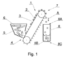
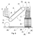
前記システムは、図1に示す第1供給コンベア1を備える。供給コンベア1は、ベルト3の外面に取り付けられた横断回収用スラット2を備えたベルトコンベアである。適切に配置されていないシガレットは、供給コンベア1の下部領域4の上に配置された、出口を有する容器5に配置される。
The system includes a
供給コンベア1の上部領域7において、シガレットは重力により(矢印Aの示す方向に)落下する。落下するシガレット6を受けるために、前記上部領域7の下にシュート8が配置されている(図1及び2参照)。上方から見て(図3参照)、シュート8の入口8Aは、供給コンベア1の回収用スラット2に実質的に平行に配向されている。シュート8の底部は、水平方向に対して下向きに傾斜している(図2参照)。
In the
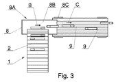
上方から見て(図3参照)、矢印Bが示す、シュート底部8B上のシガレット6の移動方向は、回収用スラット2同士の間の、供給コンベア1上のシガレットの配向に対して実質的に平行である。シュート8の底部は、側壁付近に丸められた端部をもつ平底8Bであっても、丸められた底部であってもよい。シガレットを供給する方向B、すなわちシュート8の中のシガレットの移動方向は、図3に示す一点鎖線8Dに対して平行である。
When viewed from above (see FIG. 3), the direction of movement of the
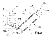
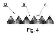
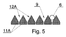
シュート8の底部8Bは、水平方向に対して、好適には15°から60°の範囲、より好適には30°から50°の範囲、最も好適には45°の角度αをなして配置される。シュート8の出口は、縦方向の整列コンベア11の下部領域10に配置されている。整列コンベア11は、多溝面として形成された上面(図4参照)を有するベルトコンベアであるか、又は複数の溝9によって構成される。変形例において、整列コンベア11は複数のベルト11Aによって構成し、その作用面は、溝を形成する逆V字型の形状とすることができる。
The bottom 8B of the
上方から見て、整列コンベア11は、溝9が線8Dに対して平行に向けられるように配置されており、シガレットがベルト12の作用面に直接搬送されたときに有利となる。しかし、図3′に示すように、システムの異なる構成を得るために、湾曲部材等の中間部材8′も使用することができる。図3′に示すように、湾曲中間部材8′は、シガレット移動方向を変更する、追加の傾斜したシュートで構成することができる。
When viewed from above, the
湾曲素子8′の出口8C′は、コンベア11の作用面12の上に配置することができる。出口8C′にて、シガレット6が、線8D′に沿って進み、さらにコンベア11へと進むように方向付けるために、出口8C′を直線状にすることができる。
The
施工条件等の何らかの理由により、システムの異なる構成が必要な場合には、直線状の中間シュートも使用することができる。シュート8を、より複雑な形状、例えば僅かにねじれた形状として、出口を、上方から見て、入口に対して回転させることもできる。
If for some reason, such as construction conditions, a different system configuration is required, a linear intermediate chute can also be used. The
整列コンベア11は、水平方向に対して、15°から60°の範囲、より好適には30°から50°の範囲、最も好適には40°の角度βをなして配置することができる。コンベアのベルトは、0.lm/sからlm/sの範囲、好適には0.3m/sから0.8m/sの範囲、最も好適には0.7m/sの速度で移動し、角度βが大きいほど、高速度であることが望ましい。
The
図6は、廃棄シガレットからたばこを回収するためのシステムを示す。このシステムの一部については、既に、本発明に係る、ロッド状要素を配置するためのシステムを示す図1〜5に言及しつつ説明されている。 FIG. 6 shows a system for collecting tobacco from waste cigarettes. Part of this system has already been described with reference to FIGS. 1 to 5 which show a system for placing rod-like elements according to the invention.
図6に示すように、本発明に係るたばこを回収するシステムにおいて、整列コンベア11の上部領域13からのシガレットは、移送されてきたシガレット6を平行配向に整列させるためにアセンブリ14内に投入される。整列アセンブリ14は、図の紙面に対して垂直方向に、相互に往復移動可能なロッド15を備える。中間ホッパー17は、整列アセンブリ14の下に配置されている。ホッパー17は、壁18及び19によって横から制限されており、その底部側は移送筒21の外周面20により制限されている。
As shown in FIG. 6, in the system for collecting cigarettes according to the present invention, cigarettes from the
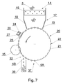
移送筒21は、その外周面20に、シガレット6を移送するための、複数の溝22を有する。シガレット6は、溝の底部に形成された開口部を介して加えられる負圧によって溝22の中に維持することができる。さらに、シガレット6は、筒21により移送される間、既知の湾曲ガイド(図示せず)によって溝22内に維持することができ、該湾曲ガイドの内面は移送筒21の外周面20の湾曲部の曲率半径よりも若干大きな曲率半径を有する。
The
移送される間、連続する各シガレットは、運転制御手段の運転領域を通過する。この領域は、走査ヘッド24の運転の第一領域23を含む。走査ヘッド24の機能は、シガレットのたばこ部分6A又はフィルタ部分6Bがどの方向を向いているかを検出することにより、連続する各シガレットの位置を確認することである。走査ヘッド24は、シガレット6の端面に向けたセンサ25、26、又はシガレットの筒状の側面に向けた他のセンサ27、28を備えてよい。
While being transferred, each successive cigarette passes through the operation area of the operation control means. This area includes the
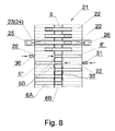
移送筒21付近で、かつ運転制御手段の運転領域の第2領域内には、溝22に沿ってシガレット6をシフトさせることで、シガレットのフィルタ部分の境界線を移送筒21の周りの共通の周線上に位置させるための、加圧エアノズル30、31が設けられている。センサ24及び25をもつ走査ヘッド24、及び加圧エアノズル30、31を、移送筒21の外周面の展開図を示す図8に示す。
By shifting the
移送筒21の付近に、シガレットのたばこ部分をそのフィルタ部分から分離する手段が設けられている。この実施形態において、分離手段は、たばこ部分6Aをフィルタ部分6Bから切り離すための2つのディスクナイフ35により形成されている。図8において、シガレット6が移送筒21の溝22に沿ってシフトされた状況の、シガレット6のフィルタ部分の境界線が破線33により示され、該破線33は筒21の外周にわたって延びる。さらに、線33はディスクナイフ35の位置を示す。
Means for separating the cigarette tobacco portion from the filter portion is provided in the vicinity of the
領域32(図7参照)において、フィルタ部分6Bは、溝22の底部にある開口部を通って送られた加圧空気又は機械式スクレーパによって、移送筒21から容器36内へと落とされる。移送筒21に残ったたばこ部分6Aは落下領域37へと移送され、加圧空気によって溝22から落とされる。落下チャネル38が移送筒21の下の落下領域37に配置されている。2つの加圧エアノズル39及び40が、落下チャネル38付近に配置されており、それらの機能は落下チャネル38からたばこ部分6Aを飛ばし、出口チャネル41内へと導入することである。
In region 32 (see FIG. 7), the
ノズル39はチャネル38と同軸上に配置されている一方、ノズル40はチャネル38に対して斜めに配置されており、ノズル39から離れて位置するたばこ部分6Aを飛ばすのに役立つ。切断アセンブリが出口チャネル41の上に設けられている。本実施形態において、移送されたたばこ部分6Aの紙ラッパーを切断するためのディスクナイフ42により形成されている。
The
ロッド状要素を配置するためのシステム、及び一部がロッド状要素を配置するためのシステムで構成されている、廃棄シガレットからたばこを回収するためのシステムの運転について以下に記載する。適切に配置されていないシガレット6は、容器5内に投入される。シガレットは容器5から、供給コンベア1の下部領域にある、供給コンベア1の連続する回収用スラット2に引き取られ、コンベア1を上に向かって移送される。上部領域7において、シガレットは入口8Aを通ってシュート8内へと、底部8Bまで落下する。底部8Bが傾斜しているため、シガレット6は底部8Bにぶつかるとひっくり返り、傾斜に沿って下へと滑り、出口8Cを通ってシュートの外へと出ていき、シガレットの先端部が、整列コンベア11の下部領域10において整列コンベア11の溝付きの作用面12と接触する。ロッド状要素を配置するためのシステム、そして、本発明に係る、廃棄シガレットからたばこを回収するためのシステムの最も具体的な特徴は、シュート8の出口と整列コンベア11の開始部分との特別な並置、水平方向に対するこれらの素子の適切な傾斜角度の選択、及び整列コンベアベルトの移動速度、の組み合わせにある。シュート8及び整列コンベア11の傾斜角度の、設計された具体的な組み合わせにより、シガレットは、シュート8から整列コンベア11への移動に際して、60°から150°の範囲の角度γで回転することで、移動方向を変更する。
The operation of the system for collecting tobacco from waste cigarettes, which is composed of a system for placing rod-like elements and a system for placing rod-like elements in part, is described below.
シガレットは、角度γが75°から110°の範囲にあるときに、整列コンベア11の溝9の中に、有効に配置されるが、シュート8と整列コンベア11との最も効果的な配置は、シガレットが85°から95°の範囲の角度γ、すなわちほぼ直角にてひっくり返る配置である。上述の、システムの素子の具体的な配置及びそれらの運転パラメータにより、シガレット端部は作用面12と接触すると、上に引っ張り上げられ、結果として、シガレットは溝9からそれずに、シュート8の出口又はシュートの拡張部分を構成する中間部材から、直接溝に沿って上へと進んでいく。ロッド状要素を配置するためのシステムを運転させると、適切に配置されていないロッド状要素のかたまりから適切に配置された別々の要素であって、整列コンベア11の溝22の中で互いに対して、及び移送方向に対して平行に移送された要素の連続へと変換される。
The cigarette is effectively placed in the
整列コンベア11の上部領域13にて、シガレットは放り出され、結果的に中間ホッパー17にて回収されたシガレットの最上層に落下するが、有利には中間ホッパー17の上に配置された整列アセンブリ14の上に落下する。ロッド15をもつ整列アセンブリ14は、最上部にあるシガレット6の斜めの配向を完全に防止するために、水平方向に往復移動する。中間ホッパー17を出ると、シガレットは移送ドラム21の溝22へと導入され、その外周面上で移送される。
In the
シガレット6は、走査ヘッド24の運転領域23を通って移送される。各シガレット6の配向に関する情報は、適切な加圧エアノズル30又は31(図8参照)により形成された手段のスイッチを入れるための運転制御手段にて使用される。
The
ノズル30及び31は、シガレット6をシフトさせて、移送筒の外周面20の中央部において、フィルタ部分の境界線を破線33に沿うようにして、シガレット6のフィルタ部分6Bを特定する。図8において、ノズル30はシガレット6′を右にシフトさせ、ノズル31はシガレット6″を左にシフトさせる。
The
このように配置されたシガレット6は、図8に示す線33に沿ってシガレットを切断するディスクナイフ35の運転領域を通って移送され、該ナイフ35はたばこ部分6Aをフィルタ部分6Bから分離させる。切断されたシガレットは、移送筒21によって移送され、フィルタ部分6Bは、既知の方法、例えば加圧空気によって又は機械的に、筒21から容器36内に落とされる。たばこ部分6Aは、ドラム21上に残り、落下領域37へと移送される。この領域において、たばこ部分6Aは、落下領域38を通って、ノズル39及び/又は40によって放り出される。各たばこ部分6Aは出口チャネル41に導入され、該出口チャネル41に沿って先へと進み、その間に各たばこ部分6Aの紙ラッパーが切断アセンブリ、特にディスクナイフ42によって縦方向に切断される。
The
Claims (17)
適切に配置されていないロッド状要素(6)のための容器(5)と、
供給コンベア(1)と、
シュート(8)と、
前記整列コンベア(11)と、
を備え、
前記容器(5)から供給された前記ロッド状要素(6)は前記供給コンベア(1)によって前記シュート(8)に移送され、
前記ロッド状要素(6)は前記供給コンベア(1)上で移動方向に対して横方向に配置され、
前記シュート(8)の底部は水平方向に対して角度(α)をなして下向きに傾斜しており、
縦方向の溝をもつ前記整列コンベア(11)の入口端部は前記シュート(8)の出口端部(8C)の下流に位置しており、
前記整列コンベア(11)は、水平方向に対して角度(β)をなして上向きに傾斜しているとともに、前記ロッド状要素(6)を前記シュート(8)の出口端部(8C)から前記整列コンベア(11)の上方に向かって、前記ロッド状要素(6)を前記シュート(8)から前記整列コンベア(11)の溝(9)の中へと該溝に沿って入れることができる速度で運搬することを特徴とする、システム。 A system for arranging rod-shaped elements, in particular cigarettes, on a longitudinally aligned conveyor (11) along the direction of movement of the conveyor,
A container (5) for a rod-like element (6) that is not properly positioned;
A supply conveyor (1);
Shoot (8),
The alignment conveyor (11);
With
The rod-like element (6) supplied from the container (5) is transferred to the chute (8) by the supply conveyor (1),
The rod-shaped element (6) is arranged transversely to the moving direction on the supply conveyor (1),
The bottom of the chute (8) is inclined downward at an angle (α) with respect to the horizontal direction,
The inlet end of the alignment conveyor (11) with longitudinal grooves is located downstream of the outlet end (8C) of the chute (8);
The alignment conveyor (11) is inclined upward at an angle (β) with respect to the horizontal direction, and the rod-shaped element (6) is moved from the outlet end (8C) of the chute (8). The speed at which the rod-like element (6) can be inserted along the groove from the chute (8) into the groove (9) of the alignment conveyor (11) toward the upper side of the alignment conveyor (11). A system characterized by being transported by
該整列コンベア(11)のベルト(12)の上面は多溝面として形成されており、又は、前記整列コンベア(11)は複数のベルトを含んでおり、該複数のベルトの作用面はそれぞれ逆V字型の形状であることを特徴とする、請求項1に記載のシステム。 The alignment conveyor (11) is a belt conveyor,
The upper surface of the belt (12) of the alignment conveyor (11) is formed as a multi-groove surface, or the alignment conveyor (11) includes a plurality of belts, and the working surfaces of the plurality of belts are reversed. The system according to claim 1, wherein the system is V-shaped.
たばこ部分の紙ラッパーを縦方向に切断するためのアセンブリ(42)と、
たばこを紙ラッパーから取り除くためのアセンブリと、
を備え、
ラッパーを縦方向に切断するための前記アセンブリ(42)の上流において、請求項1〜10のいずれか一項に記載のロッド状要素を配置するためのシステムを備え、
前記ロッド状要素を配置するためのシステムの下流において、前記ロッド状要素を配置するためのシステムによって搬送されたシガレットを受けるための中間ホッパー(17)が配置されており、
溝付き外周面(20)を有する移送筒(21)が、シガレットを移送するために、前記ホッパー(17)の下に設けられており、
前記たばこを回収するためのシステムは、
前記移送筒の前記溝付き外周面(20)の溝(22)の中のシガレットをシフトさせることで、該シガレットのフィルタ部分の境界線を前記移送筒(21)の周りの共通の周線上に位置させるための運転制御手段と、
前記移送筒(21)の前記溝(22)の中に配置されたシガレット(6)のたばこ部分(6A)をフィルタ部分(6B)から分離させる手段(35)と、
をさらに備えることを特徴とする、システム。 A system for collecting tobacco from waste cigarettes by separating the filter portion of the waste cigarette from the tobacco portion,
An assembly (42) for longitudinally cutting the paper wrapper of the tobacco portion;
An assembly for removing cigarettes from paper wrappers;
With
Comprising a system for positioning a rod-like element according to any one of claims 1 to 10, upstream of the assembly (42) for longitudinally cutting a wrapper,
An intermediate hopper (17) for receiving a cigarette conveyed by the system for positioning the rod-shaped element is disposed downstream of the system for positioning the rod-shaped element;
A transfer cylinder (21) having a grooved outer peripheral surface (20) is provided under the hopper (17) for transferring cigarettes,
The system for collecting the tobacco is:
By shifting the cigarette in the groove (22) of the grooved outer peripheral surface (20) of the transfer cylinder, the boundary line of the filter portion of the cigarette is placed on a common circumference around the transfer cylinder (21). Operation control means for positioning;
Means (35) for separating the tobacco portion (6A) of the cigarette (6) disposed in the groove (22) of the transfer cylinder (21) from the filter portion (6B);
The system further comprising:
前記移送筒の前記溝付き外周面(20)上の、互いに連続するシガレットのそれぞれの側面及び/又は少なくとも一方の端面を走査するための走査ヘッド(24)と、
前記溝(22)に沿って前記シガレット(6)をシフトする加圧エアノズル(30、31)と、
備えることを特徴とする、請求項11に記載のシステム。 The operation control means includes
A scanning head (24) for scanning each side surface and / or at least one end surface of cigarettes continuous with each other on the grooved outer peripheral surface (20) of the transfer cylinder;
A pressurized air nozzle (30, 31) for shifting the cigarette (6) along the groove (22);
The system according to claim 11, comprising:
適切に配置されていないロッド状要素(6)を、供給コンベア(1)に供給するステップであって、前記ロッド状要素(6)が前記供給コンベア(1)上に前記移動方向に対して横方向に配置される、ステップと、
その後、前記ロッド状要素(6)を、前記コンベア(1)に沿って供給されるときの前記ロッド状要素の軸の方向に対して平行に、前記供給コンベア(1)からシュート(8)を通って下方に向かって、縦方向の溝をもつ整列コンベア(11)へと移送するステップと、
を含み、
前記シュート(8)の底部は水平方向に対して角度(α)をなして下向きに傾斜しており、
前記整列コンベア(11)によって前記ロッド状要素(6)は上方に向かって移送され、
移送の方向(C)は、前記ロッド状要素(6)の軸に対して平行であるとともに、水平方向に対して角度(β)をなして傾斜しており、
前記ロッド状要素(6)を前記整列コンベア(11)に供給する速度は、前記シュート(8)からの前記ロッド状要素(6)が、前記整列コンベア(11)の溝(9)の中へ、該溝に沿って配向された状態で、入ることを可能にするように調整されている、方法。 A method for placing rod-like elements, in particular cigarettes, on a longitudinally aligned conveyor, parallel to the direction of movement along the conveyor,
Supplying a rod-like element (6) not properly arranged to the supply conveyor (1), the rod-like element (6) being transverse to the direction of movement on the supply conveyor (1); Steps arranged in a direction;
Thereafter, the chute (8) is fed from the supply conveyor (1) in parallel to the direction of the axis of the rod-like element when the rod-like element (6) is fed along the conveyor (1). Passing downwards to an alignment conveyor (11) with longitudinal grooves;
Including
The bottom of the chute (8) is inclined downward at an angle (α) with respect to the horizontal direction,
The rod-like element (6) is transferred upward by the alignment conveyor (11),
The direction of transfer (C) is parallel to the axis of the rod-like element (6) and is inclined at an angle (β) with respect to the horizontal direction,
The speed at which the rod-shaped element (6) is fed to the alignment conveyor (11) is such that the rod-shaped element (6) from the chute (8) moves into the groove (9) of the alignment conveyor (11). , Adjusted to allow entry, oriented along the groove.
Applications Claiming Priority (3)
| Application Number | Priority Date | Filing Date | Title |
|---|---|---|---|
| PLPL398256 | 2012-02-28 | ||
| PL398256A PL221773B1 (en) | 2012-02-28 | 2012-02-28 | Method and system for organizing rod-like elements and system for the recovery of tobacco cigarette waste |
| PCT/PL2013/050007 WO2013129952A1 (en) | 2012-02-28 | 2013-02-21 | Method and system for arranging rod-like elements and system for recovering tobacco from waste cigarettes |
Publications (2)
| Publication Number | Publication Date |
|---|---|
| JP2015513402A true JP2015513402A (en) | 2015-05-14 |
| JP6042913B2 JP6042913B2 (en) | 2016-12-14 |
Family
ID=47891877
Family Applications (1)
| Application Number | Title | Priority Date | Filing Date |
|---|---|---|---|
| JP2014559860A Expired - Fee Related JP6042913B2 (en) | 2012-02-28 | 2013-02-21 | Method and system for placing rod-like elements and system for collecting tobacco from waste cigarettes |
Country Status (9)
| Country | Link |
|---|---|
| US (1) | US9993021B2 (en) |
| EP (1) | EP2819533B1 (en) |
| JP (1) | JP6042913B2 (en) |
| CN (1) | CN104114045B (en) |
| BR (1) | BR112014016475A8 (en) |
| HU (1) | HUE029944T2 (en) |
| PL (1) | PL221773B1 (en) |
| RU (1) | RU2604442C2 (en) |
| WO (1) | WO2013129952A1 (en) |
Cited By (1)
| Publication number | Priority date | Publication date | Assignee | Title |
|---|---|---|---|---|
| JP2019209328A (en) * | 2018-06-01 | 2019-12-12 | 小智研発股▲フン▼有限公司Miniwiz Co.,Ltd. | Method and apparatus for recycling cigarette waste |
Families Citing this family (14)
| Publication number | Priority date | Publication date | Assignee | Title |
|---|---|---|---|---|
| EP3065579B1 (en) | 2013-11-04 | 2022-07-27 | Philip Morris Products S.A. | System and method for transferring rod-shaped articles |
| EP3015003B1 (en) * | 2014-10-28 | 2018-06-13 | Köhl Maschinenbau AG | Sorting device for long articles, especially for cigarettes |
| PL230026B1 (en) * | 2015-06-26 | 2018-09-28 | Int Tobacco Machinery Poland Spolka Z Ograniczona Odpowiedzialnoscia | Device for slitting cigarettes and method for slitting cigarettes |
| ITUA20162079A1 (en) * | 2016-03-29 | 2017-09-29 | Tema Automazioni S R L | METHOD FOR THE CONVEYANCE OF ELONGATED ELEMENTS TOWARDS AN AUTOMATIC MACHINE AND DEVICE FEEDER FOR AUTOMATIC MACHINES USING THIS METHOD |
| CN106395241A (en) * | 2016-09-23 | 2017-02-15 | 黄飞必 | Blood collecting tube conveying device |
| CN107902376B (en) * | 2017-12-19 | 2024-12-20 | 李德福 | A plugging and self-arranging array machine in the production of activated carbon filter tips for cigarettes |
| JP7067960B2 (en) * | 2018-02-28 | 2022-05-16 | シスメックス株式会社 | Pipette tip supply mechanism and pipette tip supply method |
| CN109987381B (en) * | 2019-04-15 | 2024-04-16 | 中交第二航务工程局有限公司 | Close-range three-dimensional concrete transportation system |
| DE102019122472A1 (en) * | 2019-08-21 | 2021-02-25 | Hauni Maschinenbau Gmbh | Swash plate for a conveyor drum in the tobacco processing industry |
| CN112493530B (en) * | 2020-11-24 | 2022-09-23 | 河南中烟工业有限责任公司 | Automatic turning device for visually distinguishing cigarette |
| CN113104525A (en) * | 2021-04-25 | 2021-07-13 | 永州市冷水滩区五谷香农产品加工有限责任公司 | Dedicated lifting machine of rice production |
| CN113478084B (en) * | 2021-07-29 | 2024-08-16 | 武汉淡雅香生物科技有限公司 | Smoke pipe punching device and smoke pipe punching method |
| CN113415488B (en) * | 2021-08-19 | 2021-10-29 | 南通宝田包装科技有限公司 | Automatic arrangement device for production |
| CN118107845B (en) * | 2024-04-15 | 2025-09-26 | 湖北中烟工业有限责任公司 | A roller-type cigar conveying and sleeve system |
Citations (4)
| Publication number | Priority date | Publication date | Assignee | Title |
|---|---|---|---|---|
| DE2032706A1 (en) * | 1970-07-02 | 1972-01-05 | Hauni-Werke Körber & Co KG, 2050 Hamburg | Method and device for opening cigarettes |
| US3665931A (en) * | 1969-07-18 | 1972-05-30 | Amf Inc | Cigarette ripping device |
| JPH0489715A (en) * | 1990-08-02 | 1992-03-23 | Kibun Foods Inc | Carrying line device for rod shaped kneaded product |
| JP2011188848A (en) * | 2010-03-11 | 2011-09-29 | Internatl Tobacco Machinery Poland Sp Zoo | Method and assembly for opening cigarette wrapper in machine for recovering tobacco from defective and/or substandard cigarette |
Family Cites Families (10)
| Publication number | Priority date | Publication date | Assignee | Title |
|---|---|---|---|---|
| DE1106227B (en) | 1954-01-03 | 1961-05-04 | Hauni Werke Koerber & Co Kg | Device for removing the mouthpieces from filter mouthpiece cigarettes |
| US3404688A (en) | 1965-06-04 | 1968-10-08 | Reynolds Tobacco Co R | Apparatus for disassembling filter and cigarette assemblies |
| DE1532266A1 (en) | 1966-01-21 | 1970-01-22 | Molins Machine Co Ltd | Device for tearing open faulty cigarettes |
| US4117852A (en) * | 1976-08-31 | 1978-10-03 | Philip Morris Incorporated | Method and apparatus for reclaiming tobacco from cigarettes |
| DE3839431A1 (en) | 1988-11-23 | 1990-05-31 | Fr Niepmann Gmbh U Co Maschf | METHOD AND DEVICE FOR RECOVERY TOBACCO FROM DEFECTIVE CIGARETTES |
| US5076291A (en) | 1990-01-03 | 1991-12-31 | Philip Morris Incorporated | Method and apparatus for detipping loose cigarettes |
| DE4439189C2 (en) * | 1994-11-03 | 1998-06-18 | Bat Cigarettenfab Gmbh | Device for returning tobacco from cigarettes separated by a cigarette machine |
| RU2100944C1 (en) * | 1996-01-03 | 1998-01-10 | Малое внедренческое предприятие "ПЛЭКОЛ" | Method for reprocessing return wastes of tobacco industry |
| DE19847152A1 (en) * | 1998-10-13 | 2000-04-20 | Decoufle Sarl | Conveying system used for oval cross-section cigarettes has conveyor designed to turn cigarettes from major axis horizontal to major axis vertical |
| CN201243617Y (en) * | 2008-07-26 | 2009-05-27 | 常德瑞华制造有限公司 | Device for arranging cigarette in pipe of machine for recycling tobacco shred of waste cigarette |
-
2012
- 2012-02-28 PL PL398256A patent/PL221773B1/en unknown
-
2013
- 2013-02-21 CN CN201380008630.7A patent/CN104114045B/en not_active Expired - Fee Related
- 2013-02-21 HU HUE13710081A patent/HUE029944T2/en unknown
- 2013-02-21 RU RU2014138403/12A patent/RU2604442C2/en active
- 2013-02-21 BR BR112014016475A patent/BR112014016475A8/en not_active Application Discontinuation
- 2013-02-21 US US14/381,299 patent/US9993021B2/en not_active Expired - Fee Related
- 2013-02-21 WO PCT/PL2013/050007 patent/WO2013129952A1/en not_active Ceased
- 2013-02-21 EP EP13710081.4A patent/EP2819533B1/en not_active Not-in-force
- 2013-02-21 JP JP2014559860A patent/JP6042913B2/en not_active Expired - Fee Related
Patent Citations (4)
| Publication number | Priority date | Publication date | Assignee | Title |
|---|---|---|---|---|
| US3665931A (en) * | 1969-07-18 | 1972-05-30 | Amf Inc | Cigarette ripping device |
| DE2032706A1 (en) * | 1970-07-02 | 1972-01-05 | Hauni-Werke Körber & Co KG, 2050 Hamburg | Method and device for opening cigarettes |
| JPH0489715A (en) * | 1990-08-02 | 1992-03-23 | Kibun Foods Inc | Carrying line device for rod shaped kneaded product |
| JP2011188848A (en) * | 2010-03-11 | 2011-09-29 | Internatl Tobacco Machinery Poland Sp Zoo | Method and assembly for opening cigarette wrapper in machine for recovering tobacco from defective and/or substandard cigarette |
Cited By (1)
| Publication number | Priority date | Publication date | Assignee | Title |
|---|---|---|---|---|
| JP2019209328A (en) * | 2018-06-01 | 2019-12-12 | 小智研発股▲フン▼有限公司Miniwiz Co.,Ltd. | Method and apparatus for recycling cigarette waste |
Also Published As
| Publication number | Publication date |
|---|---|
| JP6042913B2 (en) | 2016-12-14 |
| WO2013129952A1 (en) | 2013-09-06 |
| EP2819533A1 (en) | 2015-01-07 |
| BR112014016475A8 (en) | 2017-07-04 |
| BR112014016475A2 (en) | 2017-06-13 |
| RU2014138403A (en) | 2016-04-20 |
| US9993021B2 (en) | 2018-06-12 |
| US20150101621A1 (en) | 2015-04-16 |
| CN104114045A (en) | 2014-10-22 |
| PL221773B1 (en) | 2016-05-31 |
| HUE029944T2 (en) | 2017-04-28 |
| RU2604442C2 (en) | 2016-12-10 |
| EP2819533B1 (en) | 2016-05-11 |
| PL398256A1 (en) | 2013-09-02 |
| CN104114045B (en) | 2016-11-02 |
Similar Documents
| Publication | Publication Date | Title |
|---|---|---|
| JP6042913B2 (en) | Method and system for placing rod-like elements and system for collecting tobacco from waste cigarettes | |
| KR101504386B1 (en) | Method of compiling groups of segments in a process of producing multisegment filters and apparatus for preparing and compiling segments in groups in a process of producing multisegment filters | |
| KR101398745B1 (en) | Filter component cutting system | |
| CN111432664B (en) | Supplementing device, equipment for producing multi-section bar and method for producing multi-section bar | |
| EP2750525B1 (en) | Tobacco reclaim from waste cigarettes | |
| US3224451A (en) | Apparatus for removal of tips from scrap cigarettes | |
| EP3579707B1 (en) | Orientation and feeding system and method for feeding cigarettes and providing longitudinal orientation to cigarettes, device and method for recovering tobacco from cigarettes | |
| CN106954665A (en) | Device and method for shifting sausage portion | |
| EP1985192B1 (en) | Shredded tobacco material feeder of a cigarette manufacturing apparatus | |
| JP2004528645A6 (en) | Unit device for feeding cigarettes into packing machines | |
| US8930016B2 (en) | Method and system for arranging rod-like elements | |
| EP2782461A1 (en) | Apparatus and method for deconstructing a smoking article | |
| JP2011139702A5 (en) | ||
| JP2011139702A (en) | Paper removal for oscillating conveyer pot for tobacco processing industry | |
| KR101828738B1 (en) | Counting device for automatic seasoned laver Processing line | |
| KR100331389B1 (en) | Apparatus and method used for unpacking of packaged goods | |
| EP3197302B1 (en) | Machine for making smokers' articles | |
| RU2759456C2 (en) | Device and feeding method intended for feeding spherical objects in tobacco industry equipment | |
| CN106455679B (en) | Method and apparatus for removing tobacco from cigarettes | |
| CN1954733B (en) | Apparatus for feeding filters | |
| JPH11262731A (en) | Foreign matter excluding apparatus | |
| JP7160328B2 (en) | scallop feeder | |
| JPH11278422A (en) | Stacker bundler for bag-making machine | |
| WO2014076224A1 (en) | Plant material alignment device and method thereof | |
| JP2004180605A (en) | Hopper apparatus for rod-shaped article |
Legal Events
| Date | Code | Title | Description |
|---|---|---|---|
| A621 | Written request for application examination |
Free format text: JAPANESE INTERMEDIATE CODE: A621 Effective date: 20150612 |
|
| A977 | Report on retrieval |
Free format text: JAPANESE INTERMEDIATE CODE: A971007 Effective date: 20160316 |
|
| A131 | Notification of reasons for refusal |
Free format text: JAPANESE INTERMEDIATE CODE: A131 Effective date: 20160412 |
|
| A521 | Request for written amendment filed |
Free format text: JAPANESE INTERMEDIATE CODE: A523 Effective date: 20160615 |
|
| TRDD | Decision of grant or rejection written | ||
| A01 | Written decision to grant a patent or to grant a registration (utility model) |
Free format text: JAPANESE INTERMEDIATE CODE: A01 Effective date: 20161108 |
|
| A61 | First payment of annual fees (during grant procedure) |
Free format text: JAPANESE INTERMEDIATE CODE: A61 Effective date: 20161110 |
|
| R150 | Certificate of patent or registration of utility model |
Ref document number: 6042913 Country of ref document: JP Free format text: JAPANESE INTERMEDIATE CODE: R150 |
|
| R250 | Receipt of annual fees |
Free format text: JAPANESE INTERMEDIATE CODE: R250 |
|
| R250 | Receipt of annual fees |
Free format text: JAPANESE INTERMEDIATE CODE: R250 |
|
| LAPS | Cancellation because of no payment of annual fees |