JP2015509190A - Diving energy generation module - Google Patents
Diving energy generation module Download PDFInfo
- Publication number
- JP2015509190A JP2015509190A JP2014552636A JP2014552636A JP2015509190A JP 2015509190 A JP2015509190 A JP 2015509190A JP 2014552636 A JP2014552636 A JP 2014552636A JP 2014552636 A JP2014552636 A JP 2014552636A JP 2015509190 A JP2015509190 A JP 2015509190A
- Authority
- JP
- Japan
- Prior art keywords
- power generation
- reactor
- generation module
- forming
- compartment
- Prior art date
- Legal status (The legal status is an assumption and is not a legal conclusion. Google has not performed a legal analysis and makes no representation as to the accuracy of the status listed.)
- Granted
Links
- 230000009189 diving Effects 0.000 title description 6
- XLYOFNOQVPJJNP-UHFFFAOYSA-N water Substances O XLYOFNOQVPJJNP-UHFFFAOYSA-N 0.000 claims abstract description 113
- 238000003860 storage Methods 0.000 claims abstract description 96
- 238000010248 power generation Methods 0.000 claims abstract description 83
- 238000001035 drying Methods 0.000 claims abstract description 49
- 239000013535 sea water Substances 0.000 claims abstract description 17
- 238000010791 quenching Methods 0.000 claims abstract description 16
- 238000009826 distribution Methods 0.000 claims abstract description 10
- 230000002093 peripheral effect Effects 0.000 claims description 17
- 238000011144 upstream manufacturing Methods 0.000 claims description 9
- 238000001914 filtration Methods 0.000 claims description 8
- 230000006837 decompression Effects 0.000 claims description 7
- 230000004888 barrier function Effects 0.000 claims description 6
- 239000011810 insulating material Substances 0.000 claims description 6
- 239000000463 material Substances 0.000 claims description 4
- BTBUEUYNUDRHOZ-UHFFFAOYSA-N Borate Chemical compound [O-]B([O-])[O-] BTBUEUYNUDRHOZ-UHFFFAOYSA-N 0.000 claims description 3
- 230000000171 quenching effect Effects 0.000 abstract description 9
- 238000001816 cooling Methods 0.000 description 35
- 239000012530 fluid Substances 0.000 description 6
- 238000013022 venting Methods 0.000 description 5
- 238000005192 partition Methods 0.000 description 4
- 238000002347 injection Methods 0.000 description 3
- 239000007924 injection Substances 0.000 description 3
- 238000004873 anchoring Methods 0.000 description 2
- 230000005611 electricity Effects 0.000 description 2
- 230000006872 improvement Effects 0.000 description 2
- 239000008239 natural water Substances 0.000 description 2
- 239000002245 particle Substances 0.000 description 2
- 239000012857 radioactive material Substances 0.000 description 2
- 238000013459 approach Methods 0.000 description 1
- 150000001642 boronic acid derivatives Chemical group 0.000 description 1
- 239000003990 capacitor Substances 0.000 description 1
- 239000000498 cooling water Substances 0.000 description 1
- 230000006866 deterioration Effects 0.000 description 1
- 238000010586 diagram Methods 0.000 description 1
- 230000000694 effects Effects 0.000 description 1
- 230000007613 environmental effect Effects 0.000 description 1
- 238000000605 extraction Methods 0.000 description 1
- 230000004992 fission Effects 0.000 description 1
- 230000005484 gravity Effects 0.000 description 1
- 238000010438 heat treatment Methods 0.000 description 1
- 239000010903 husk Substances 0.000 description 1
- 238000007689 inspection Methods 0.000 description 1
- 239000007788 liquid Substances 0.000 description 1
- 230000007774 longterm Effects 0.000 description 1
- 238000012423 maintenance Methods 0.000 description 1
- 238000004519 manufacturing process Methods 0.000 description 1
- 239000000155 melt Substances 0.000 description 1
- 238000002844 melting Methods 0.000 description 1
- 230000008018 melting Effects 0.000 description 1
- 239000002184 metal Substances 0.000 description 1
- 238000000034 method Methods 0.000 description 1
- 239000003758 nuclear fuel Substances 0.000 description 1
- 230000005855 radiation Effects 0.000 description 1
- 230000002285 radioactive effect Effects 0.000 description 1
- 239000003507 refrigerant Substances 0.000 description 1
- 238000007789 sealing Methods 0.000 description 1
- 239000000243 solution Substances 0.000 description 1
- 239000007921 spray Substances 0.000 description 1
- 238000012546 transfer Methods 0.000 description 1
Images


Classifications
-
- B—PERFORMING OPERATIONS; TRANSPORTING
- B63—SHIPS OR OTHER WATERBORNE VESSELS; RELATED EQUIPMENT
- B63G—OFFENSIVE OR DEFENSIVE ARRANGEMENTS ON VESSELS; MINE-LAYING; MINE-SWEEPING; SUBMARINES; AIRCRAFT CARRIERS
- B63G8/00—Underwater vessels, e.g. submarines; Equipment specially adapted therefor
- B63G8/001—Underwater vessels adapted for special purposes, e.g. unmanned underwater vessels; Equipment specially adapted therefor, e.g. docking stations
-
- G—PHYSICS
- G21—NUCLEAR PHYSICS; NUCLEAR ENGINEERING
- G21C—NUCLEAR REACTORS
- G21C9/00—Emergency protection arrangements structurally associated with the reactor, e.g. safety valves provided with pressure equalisation devices
- G21C9/016—Core catchers
-
- G—PHYSICS
- G21—NUCLEAR PHYSICS; NUCLEAR ENGINEERING
- G21C—NUCLEAR REACTORS
- G21C15/00—Cooling arrangements within the pressure vessel containing the core; Selection of specific coolants
- G21C15/18—Emergency cooling arrangements; Removing shut-down heat
-
- G—PHYSICS
- G21—NUCLEAR PHYSICS; NUCLEAR ENGINEERING
- G21C—NUCLEAR REACTORS
- G21C11/00—Shielding structurally associated with the reactor
- G21C11/02—Biological shielding ; Neutron or gamma shielding
- G21C11/04—Biological shielding ; Neutron or gamma shielding on waterborne craft
-
- G—PHYSICS
- G21—NUCLEAR PHYSICS; NUCLEAR ENGINEERING
- G21C—NUCLEAR REACTORS
- G21C9/00—Emergency protection arrangements structurally associated with the reactor, e.g. safety valves provided with pressure equalisation devices
-
- G—PHYSICS
- G21—NUCLEAR PHYSICS; NUCLEAR ENGINEERING
- G21C—NUCLEAR REACTORS
- G21C9/00—Emergency protection arrangements structurally associated with the reactor, e.g. safety valves provided with pressure equalisation devices
- G21C9/004—Pressure suppression
-
- G—PHYSICS
- G21—NUCLEAR PHYSICS; NUCLEAR ENGINEERING
- G21D—NUCLEAR POWER PLANT
- G21D3/00—Control of nuclear power plant
- G21D3/04—Safety arrangements
- G21D3/06—Safety arrangements responsive to faults within the plant
-
- B—PERFORMING OPERATIONS; TRANSPORTING
- B63—SHIPS OR OTHER WATERBORNE VESSELS; RELATED EQUIPMENT
- B63B—SHIPS OR OTHER WATERBORNE VESSELS; EQUIPMENT FOR SHIPPING
- B63B35/00—Vessels or similar floating structures specially adapted for specific purposes and not otherwise provided for
- B63B35/44—Floating buildings, stores, drilling platforms, or workshops, e.g. carrying water-oil separating devices
- B63B2035/4433—Floating structures carrying electric power plants
- B63B2035/4446—Floating structures carrying electric power plants for converting nuclear energy into electric energy
-
- G—PHYSICS
- G21—NUCLEAR PHYSICS; NUCLEAR ENGINEERING
- G21C—NUCLEAR REACTORS
- G21C13/00—Pressure vessels; Containment vessels; Containment in general
-
- G—PHYSICS
- G21—NUCLEAR PHYSICS; NUCLEAR ENGINEERING
- G21D—NUCLEAR POWER PLANT
- G21D1/00—Details of nuclear power plant
-
- Y—GENERAL TAGGING OF NEW TECHNOLOGICAL DEVELOPMENTS; GENERAL TAGGING OF CROSS-SECTIONAL TECHNOLOGIES SPANNING OVER SEVERAL SECTIONS OF THE IPC; TECHNICAL SUBJECTS COVERED BY FORMER USPC CROSS-REFERENCE ART COLLECTIONS [XRACs] AND DIGESTS
- Y02—TECHNOLOGIES OR APPLICATIONS FOR MITIGATION OR ADAPTATION AGAINST CLIMATE CHANGE
- Y02E—REDUCTION OF GREENHOUSE GAS [GHG] EMISSIONS, RELATED TO ENERGY GENERATION, TRANSMISSION OR DISTRIBUTION
- Y02E30/00—Energy generation of nuclear origin
- Y02E30/30—Nuclear fission reactors
Abstract
本発明に基づくモジュールは、電気ケーブル(6)により外部配電ステーション(7)に接続される発電手段(37)に関連する原子力蒸気発生器形成手段(30)を含む発電ユニット形成手段が内部に組み込まれる細長円筒形ボックスの形態の手段(12)を含み、手段(30)は、反応炉の安全水保管貯留部形成チャンバ(20)に関連する反応炉コンパートメント(18)の乾燥チャンバ(19)内に配置され、チャンバ(20)の外周壁(53)は海洋環境と熱交換関係にあり、乾燥チャンバは発電手段を受容しかつ乾燥チャンバ(19)の急冷水の導入のための手段(100)を含むコンパートメント(21)に関連し、手段(100)は、コンパートメント(21)においてモジュール(12)の外周壁に形成された海水流入部(101)と、海水流入部と乾燥チャンバ(19)との間の導管と、チャンバのための急冷バルブを形成する手段(102)と、を含む。The module according to the invention incorporates a power generation unit forming means including a nuclear steam generator forming means (30) associated with the power generating means (37) connected to the external power distribution station (7) by means of an electrical cable (6). Means (12) in the form of an elongated cylindrical box, wherein means (30) is in the drying chamber (19) of the reactor compartment (18) associated with the reactor safe water storage reservoir forming chamber (20). The outer wall (53) of the chamber (20) is in heat exchange relationship with the marine environment, the drying chamber receives power generation means and means (100) for introducing quenching water in the drying chamber (19) Means (100) comprising a seawater inlet formed in the outer wall of the module (12) in the compartment (21) Including 101), a conduit between the sea water inlet and a drying chamber (19), and means for forming a quench valve for the chamber (102), the.
Description
本発明は、潜水発電モジュールまたは水中発電モジュールに関するものである。 The present invention relates to a submersible power generation module or an underwater power generation module.
より詳細には、本発明は水中発電モジュールに関し、当該発電モジュールは細長円筒形ボックスの形態の手段を含み、この手段内には、電気ケーブルによって外部配電ステーションに接続される発電手段と関連付けられる原子力蒸気発生器を形成する手段を含む発電ユニットが一体的に形成されている。 More particularly, the present invention relates to an underwater power generation module, the power generation module comprising means in the form of an elongated cylindrical box, in which nuclear power associated with power generation means connected to an external power distribution station by an electrical cable. A power generation unit including means for forming a steam generator is integrally formed.
そうしたモジュールは当技術分野においては公知である。 Such modules are well known in the art.
例えば特許文献1、特許文献2、および特許文献3が参照されてもよい。 For example, Patent Literature 1, Patent Literature 2, and Patent Literature 3 may be referred to.
これらのさまざまな文献には、水中または潜水発電ユニットが開示されており、当該ユニット内には、例えば原子力蒸気発生器を形成する手段に関連付けて発電手段を組み込むことができる。 These various documents disclose submersible or submersible power generation units, in which power generation means can be incorporated, for example in connection with means for forming a nuclear steam generator.
原子力由来のエネルギーは効率的でありかつエネルギー問題や環境問題に対する有意義な解決策となるため、上述の構造物がいくつかの利点を有することが知られている。 Since energy derived from nuclear power is efficient and provides a meaningful solution to energy and environmental problems, it is known that the structure described above has several advantages.
そうした構造物はまた、特に安全性に関する問題や、津波やハリケーンなどの自然によるリスクまたは飛行機の墜落や悪意のある行為などの人によるリスクに関するいくつかの問題を解決することもできる。 Such structures can also solve some safety issues, and some other issues related to natural risks such as tsunamis and hurricanes or human risks such as airplane crashes and malicious acts.
また、それらの技術的な実現可能性および経済的妥当性が実証されていないという事実に起因して、こうしたさまざまな問題がしばらくの間、産業利用上で発生していないことも知られている。 It is also known that these various problems have not occurred in industrial use for some time due to the fact that their technical feasibility and economic validity have not been demonstrated. .
こうしたタイプの構造物を改善しようとする取り組みが、出願人により数年にわたって行われていた。 Attempts to improve these types of structures have been made by the applicant for several years.
この取り組みは、例えばいくつかの特許出願、特に参照可能な特許文献4〜10をもたらした。 This approach has resulted, for example, in several patent applications, in particular referenceable patent documents 4-10.
これら参照文献のいくつかは、特にこうしたタイプのモジュールの安全運転について、とりわけ地上に設置される発電プラントに関して最近発生した重大な事故の際のそれらモジュールの安全性について言及している。 Some of these references specifically refer to the safe operation of these types of modules, especially the safety of those modules in the event of a major accident that has recently occurred with power plants installed on the ground.
本発明の目的は、その運転の安全性をさらに向上させるために、このタイプの潜水式モジュールの、さらに他の改善案を提案することである。 The object of the present invention is to propose yet another improvement of this type of submersible module in order to further improve the safety of its operation.
そのため、本発明は、発電ユニットを形成する手段が内部に組み込まれる細長円筒形ボックスの形態の手段を含むタイプの水中発電モジュールであって、発電ユニットを形成する手段が、電気ケーブルによって外部配電ステーションに接続された発電手段に関連付けられる原子力蒸気発生器を形成する手段を含み、原子力蒸気発生器を形成する手段が、反応炉の安全水保管貯留部を形成するチャンバに関連付けられた反応炉コンパートメントの乾燥チャンバ内に配置されており、反応炉の安全水保管貯留部を形成するチャンバの外周壁は少なくとも、海洋環境と熱交換関係にあり、かつ、反応炉コンパートメントの乾燥チャンバは、発電手段を受容するためのコンパートメントに関連付けられており、かつ、コンパートメントは、反応炉を受容する乾燥チャンバの急冷水の導入のための手段を含み、当該手段は、コンパートメントの下部に配置され、かつ発電手段を受容するコンパートメントにおいてモジュールの外周壁に形成された海水流入部と、海水流入部と反応炉コンパートメントの乾燥チャンバとの間の導管と、チャンバのための急冷バルブを形成する手段と、を含む水中発電モジュールに関するものである。 Therefore, the present invention is an underwater power generation module of the type including means in the form of an elongated cylindrical box in which means for forming a power generation unit are incorporated, wherein the means for forming the power generation unit is an external distribution station by means of an electrical cable Means for forming a nuclear steam generator associated with the power generation means connected to the reactor, wherein the means for forming the nuclear steam generator is of the reactor compartment associated with the chamber forming the safe water storage reservoir of the reactor. Located in the drying chamber, the outer wall of the chamber forming the safe water storage reservoir of the reactor is at least in heat exchange relationship with the marine environment, and the drying chamber of the reactor compartment receives power generation means. And the compartment receives a reactor. Means for introducing quenching water in the drying chamber, the means being arranged at the lower part of the compartment and formed in the outer wall of the module in the compartment for receiving the power generation means, and a seawater inflow part And a means for forming a quench valve for the chamber, and an underwater power generation module.
本発明の他の態様によれば、上記水中モジュールは、以下の特徴部を1つ以上含む:
− 原子力蒸気発生手段は、少なくとも1つの反応炉容器、加圧器、蒸気発生器および主要ポンプを備える主要回路と、主要回路に平行でありかつ反応炉の安全水保管貯留チャンバ内に配置された少なくとも1つの主要受動熱交換器を含む、主要バックアップ回路と、を含む;
− 反応炉の安全水保管貯留チャンバ内に配置された主要受動熱交換器は、反応炉容器の高さより高い位置に配置されている;
− 主要バックアップ回路の各ブランチは、バルブを形成する手段を含む;
− 主要バックアップ回路は、主要ポンプの上流あるいは下流において主要回路に接続されている;
− 主要バックアップ回路は、主要ポンプから上流において主要回路に接続されており、かつ主要ポンプへのショートカットのための手段を含む;
− 原子力蒸気発生手段は、発電手段に関連付けられた二次回路と、当該二次回路に平行でありかつ水中モジュールの外側において海洋環境中に配置された二次受動熱交換器を少なくとも1つ含む、二次バックアップ回路と、を含む;
− 水中モジュールの外側において海洋環境中に配置された二次受動熱交換器は、蒸気発生器の高さより高い位置に配置されている;
− 二次バックアップ回路の各ブランチは、バルブを形成する手段を含む;
− 二次回路は、遮断バルブを形成する形成手段を含んでおり、かつ二次バックアップ回路は、これら遮断バルブ手段の間に接続されている;
− 二次回路は、発電手段を受容するコンパートメント内に部分的に延在しており、かつ二次バックアップ回路は、コンパートメントの外周壁を通過し、かつコンパートメントの外側に配置された二次受動熱交換器に接続されている;
− 反応炉コンパートメントの乾燥チャンバは、減圧手段によって、反応炉の安全水保管貯留チャンバに接続されており、減圧手段は、乾燥チャンバの上部に配置された減圧バルブを形成する手段を含み、かつ貯留部形成チャンバの下部に配置された気泡発生器を形成する手段に接続されており、かつ、貯留部形成チャンバの上部と乾燥チャンバとの間に過流量逆止め手段が設けられる;
− 原子力蒸気発生手段は、反応炉ピット内に配置される反応炉容器を含み、反応炉ピットの下部は、モジュールの外周壁に沿って配置された取水導管を形成する手段を介して反応炉の安全水保管貯留チャンバの下部に接続されており、かつ、反応炉ピットの上部は、水戻し導管を形成する手段を介して保管貯留チャンバの対応する部分に接続されている;
− バルブ手段が、取水ダクトおよび水戻しダクトを形成する手段内に配置されている;
− 断熱材料から形成されるエンクロージャが、エンクロージャと容器との間に熱バリアを形成する間隙を規定するために、反応炉容器のうち反応炉ピット内に収容される部分の周りにおいて容器の壁から所定の距離をおいて配置されている;
− 通常運転中に、エンクロージャと容器との間の間隙は、気体材料で充填されており、かつエンクロージャは、その下部において、少なくとも1つの水流入開口を含む;
− 通常運転中に、反応炉ピット内に存在する水は、ホウ酸塩水である;
− 水流入ダクトのうち、水保管貯留チャンバに接続された端部は、フィルタリングスクリーンが組み込まれる;
− 原子力蒸気発生手段は、減圧手段によって反応炉の安全水保管貯留チャンバに接続された加圧器を含む;
− 減圧手段は、反応炉の安全水保管貯留チャンバの下部に配置された気泡発生器を形成する手段に接続された減圧バルブが設けられた減圧回路を含む;
− 水の噴流の軌道を逸らすための手段が、反応炉コンパートメントの乾燥チャンバ内に海水を導入するための手段の真向かいに配置されている;
− ベントを形成する手段が、反応炉コンパートメントの乾燥チャンバと発電手段を受容するためのコンパートメントとの間において、反応炉コンパートメントの乾燥チャンバの上部に配置されている;
− ベント手段の流入部は、フィルタリング手段が組み込まれる;および、
− 水中発電モジュールは、反応炉の安全水保管貯留チャンバを反応炉容器に接続するためのバルブ手段を含む。
According to another aspect of the invention, the underwater module includes one or more of the following features:
The nuclear steam generating means comprises at least one reactor vessel, a pressurizer, a steam generator and a main pump with at least one main circuit, parallel to the main circuit and arranged in a safe water storage and storage chamber of the reactor Including a main backup circuit, including one main passive heat exchanger;
-The main passive heat exchanger located in the reactor safe water storage and storage chamber is located above the height of the reactor vessel;
Each branch of the main backup circuit includes means for forming a valve;
The main backup circuit is connected to the main circuit upstream or downstream of the main pump;
The main backup circuit is connected to the main circuit upstream from the main pump and includes means for a shortcut to the main pump;
The nuclear steam generating means comprises at least one secondary circuit associated with the power generation means and a secondary passive heat exchanger parallel to the secondary circuit and arranged in the marine environment outside the submersible module A secondary backup circuit;
-A secondary passive heat exchanger located in the marine environment outside the underwater module is located higher than the height of the steam generator;
Each branch of the secondary backup circuit includes means for forming a valve;
The secondary circuit includes forming means for forming a shut-off valve, and the secondary backup circuit is connected between these shut-off valve means;
The secondary circuit extends partially in the compartment that receives the power generation means, and the secondary backup circuit passes through the outer peripheral wall of the compartment and is arranged in the secondary passive heat located outside the compartment. Connected to the exchange;
The drying chamber of the reactor compartment is connected by a depressurizing means to a safe water storage and storage chamber of the reactor, the depressurizing means comprising means for forming a depressurizing valve located at the top of the drying chamber and storing Connected to means for forming a bubble generator located at the lower part of the section forming chamber, and an overflow check means is provided between the upper part of the reservoir forming chamber and the drying chamber;
The nuclear steam generating means comprises a reactor vessel arranged in the reactor pit, the lower part of the reactor pit being connected to the reactor via a means for forming a water intake conduit arranged along the outer peripheral wall of the module; Connected to the lower part of the safe water storage and storage chamber, and the upper part of the reactor pit is connected to a corresponding part of the storage and storage chamber via means forming a water return conduit;
-The valve means are arranged in the means forming the intake duct and the return duct;
An enclosure formed from a thermal insulating material from the vessel wall around the portion of the reactor vessel that is contained in the reactor pit to define a gap that forms a thermal barrier between the enclosure and the vessel; Arranged at a predetermined distance;
-During normal operation, the gap between the enclosure and the container is filled with a gaseous material, and the enclosure includes at least one water inlet opening in its lower part;
-During normal operation, the water present in the reactor pit is borate water;
-The end of the water inlet duct connected to the water storage and storage chamber incorporates a filtering screen;
-The nuclear steam generating means comprises a pressurizer connected to the safe water storage and storage chamber of the reactor by a depressurizing means;
The decompression means comprises a decompression circuit provided with a decompression valve connected to the means for forming a bubble generator located in the lower part of the safe water storage and storage chamber of the reactor;
The means for diverting the water jet trajectory is located directly opposite the means for introducing seawater into the drying chamber of the reactor compartment;
The means for forming a vent is arranged at the top of the drying chamber of the reactor compartment between the drying chamber of the reactor compartment and the compartment for receiving the power generation means;
-The inflow of the vent means incorporates filtering means; and
The underwater power generation module includes valve means for connecting the reactor safe water storage and storage chamber to the reactor vessel;
添付の図面を参照して単なる例示として提供される以下の説明により、本発明はより良く理解されるだろう。 The invention will be better understood with the aid of the following description, which is provided by way of example only with reference to the accompanying drawings.
上述のように、本発明は潜水式のまたは水中用の発電モジュールに関するものである。 As described above, the present invention relates to a submersible or underwater power generation module.
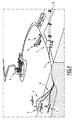
そうしたモジュールは例えば図1に図示されており、図1では参照符号1、2、3が付与されている。 Such a module is illustrated, for example, in FIG. 1, which is provided with reference numerals 1, 2, 3 in FIG.
これらモジュールは、例えば参照符号4が付与された海岸に結び付けられておりかつ海岸から離間されて潜水される。これらモジュールは例えば、参照符号5で示される発電現場において、海底に配置されるかあるいは海底からある程度の距離をおいて保持される。 These modules are associated with, for example, a beach with reference numeral 4 and are dived away from the beach. These modules are, for example, placed on the seabed or held at some distance from the seabed at the power generation site indicated by reference numeral 5.
これらのさまざまなモジュールは、参照符号6で示される電気ケーブルによって、例えばモジュールのための遠隔制御/指令センターとしても機能する外部配電ステーションに接続されている。当該センターは、例えば地上に設置されており、図1では参照符号7で示される。
These various modules are connected by an electrical cable, indicated by
この外部配電ステーションは続いて、従来通りに、参照符号8で図示される配電線を用いて、例えば参照符号9で示される近隣の都市または他の一般的な電力消費者に電力供給する配電グリッドなどへ接続される。
This external power distribution station then continues conventionally using a power distribution line illustrated by reference numeral 8, for example, a distribution grid for powering a neighboring city or other general power consumer, such as indicated by
例えば参照符号10で示される支援部などの地上の基礎構造が、生産現場への介入を可能にする支援舶などの支援手段を収容するよう考えることが可能であることに留意されたい。図1では、そうした支援手段の1つが参照符号11で示されている。 It should be noted that a ground foundation such as the support section indicated by reference numeral 10, for example, can be considered to accommodate support means such as a support vessel that allows intervention at the production site. In FIG. 1, one such support means is indicated by reference numeral 11.
支援手段は例えば、モジュールを配置すること、それらモジュールを運転状態に維持することを保証すること、または核燃料の交換など地上で実施される主要な作業のためにモジュールを回収することを可能にする。 Assistive means enable, for example, placing modules, ensuring that they remain operational, or retrieving modules for major work performed on the ground, such as nuclear fuel replacement .
実際に図2に図示されるように、当該図面において参照符号1で示される水中発電モジュールのそれぞれは、細長円筒形ボックスの形態の手段を含んでおり、一例においては、その両端は丸くなっている。 In fact, as illustrated in FIG. 2, each of the underwater power generation modules indicated by reference numeral 1 in the drawing includes means in the form of an elongated cylindrical box, and in one example its ends are rounded. Yes.
これら手段は、図2では参照符号12が付与されており、かつ例えば参照符号13で示される海底に置かれるかあるいは海底からある程度の距離を置いて保持される。そのためそれら手段は、参照符号14で示される脚アセンブリと、参照符号15で示される係留手段とを含む。係留手段は、海底におけるモジュールの位置決め、配置および保持を可能にする。
These means are provided with
脚アセンブリおよび係留手段のさまざまな実施形態が考えられる。 Various embodiments of the leg assembly and anchoring means are conceivable.
また図2には、そうしたモジュールの内部の1つの可能な実施形態を示す。当該モジュールは、実際に、互いに隣接して配置されかつ仕切りで区分される所定の数のコンパートメントを含む。 FIG. 2 also shows one possible embodiment inside such a module. The module actually includes a predetermined number of compartments arranged adjacent to each other and partitioned by a partition.
したがって例えばそうしたモジュール12は、その端部それぞれにおいて、参照符号16および17で示されるバラストの形態の手段を含んでもよい。これら手段は、例えばモジュールの潜水の制御を可能にする。
Thus, for example, such a
さらに図2の左から右へ向かって、このモジュールは、図2において参照符号18で示される反応炉コンパートメントを含んでもよい。この反応炉コンパートメントは2つの関連するチャンバに区分される。つまり厳密に言うと、原子力蒸気発生器を形成する手段が収容される(参照符号19で示される)乾燥反応炉コンパートメントチャンバと、その反応炉の安全水保管貯留部を形成する(参照符号20で示される)チャンバと、に区分される。
Further from left to right in FIG. 2, the module may include a reactor compartment, indicated by
反応炉コンパートメント18のこれらチャンバは、例えば互いに隣接して配置され、かついわゆるタイトな(漏出のない)仕切りによって隔てられている。
These chambers of the
この反応炉コンパートメントの隣には、発電手段を受容するためのコンパートメントが設けられている。このコンパートメントは、参照符号21で示されており、かつ例えばターボ交流発電機群あるいはターボ交流発電アセンブリまたは他の補助システムを備える。これについては以下で詳細に説明する。
Next to the reactor compartment, a compartment for receiving power generation means is provided. This compartment is indicated by
発電手段を受容するためのコンパートメント21に続いて、モジュール12は、例えば慣習的に電圧変換器などの電気装置を形成するコンパートメント(参照符号22で示される)と、例えばすべてのモジュールの要素のための制御ステーションを含むコンパートメント23とを含んでもよい。
Following the
当然のことながら、モジュールの内部の他の実施形態およびモジュールの要素の他の構成ならびに装置が考えられてもよい。 Of course, other embodiments within the module and other configurations and devices of the elements of the module may be envisaged.
そのため、例えば利用および処置のために乗組員に住居を提供するよう意図された居住コンパートメントを考えることもできる。 Thus, for example, a residential compartment intended to provide housing for the crew for use and treatment can be envisaged.
図3には、モジュール12のうち、反応炉コンパートメント18と、発電手段を受容するよう意図されたコンパートメント21とが設けられる部分をより詳細に図示する。
FIG. 3 shows in more detail the part of the
上述のように、反応炉コンパートメント18は、原子力蒸気発生器を形成する手段を受容し、かつ2つのチャンバ(つまり厳密に言うと反応炉を受容するための、参照符号19で示される乾燥チャンバと、参照符号20で示される安全水保管貯留チャンバと)を含むよう意図されている。
As mentioned above, the
実際に慣習的に、図3において参照符号30が付与された原子力蒸気発生手段は、参照符号31で示される主要回路を含む。当該主要回路は、少なくとも1つの反応炉容器32と、加圧器33、と蒸気発生器34と、主要ポンプ35と、を有する。
In practice, the nuclear steam generating means, which is provided with
これら原子力蒸気発生手段30、特にその蒸気発生器34は、反応炉を受容するコンパートメント18と発電手段を受容するコンパートメント21とを分離する仕切りを通過する二次回路を含んでおり、当該二次回路は、発電手段に関連付けられている。
These nuclear steam generating means 30, in particular its
図3において、二次回路が参照符号36で示されており、かつ発電手段が参照符号37で示されており、そしてこれら二次回路36および発電手段37はコンパートメント21内に配置されている。
In FIG. 3, the secondary circuit is indicated by
実際に、これら発電手段37は例えば、図3において参照符号38で示されるタービンを含む。当該タービンは、図3において参照符号39で示される交流機と、参照符号40で示されるキャパシタと、参照符号41で示される二次ポンプとに関連付けられる。
In practice, these power generation means 37 include, for example, a turbine denoted by
こうした発電手段の構造は、理解しやすくするためにここでは簡単化されている。実際には、周知の通り、熱力学サイクルのアウトプットを高めるためにより複雑である。 The structure of such power generation means is simplified here for ease of understanding. In practice, as is well known, it is more complex to increase the output of the thermodynamic cycle.
また従来通りに、蒸気発生手段30は、例えば主要な水損失事故の場合、さまざまな圧力で蒸気発生手段30内に水を噴射できるようにする種々の手段に接続される。 As is conventional, the steam generating means 30 is connected to various means that allow water to be injected into the steam generating means 30 at various pressures, for example in the event of a major water loss accident.
これら手段は、例えば図3では参照符号50で示されており、事故の特性および選択されるバックアップ方法に応じて、例えば高圧、中圧、低圧で、反応炉内に水を噴射するための噴射手段を備える。 These means are indicated, for example, by reference numeral 50 in FIG. 3 and are used for injecting water into the reactor, for example at high, medium and low pressure, depending on the characteristics of the accident and the backup method selected. Means.
したがって例えば安全水保管貯留チャンバ20を、図3において参照符号51で示される導管を用いて、反応炉容器32に接続できる。この導管は、参照符号52で示されるバルブ手段と組み合わせられる。
Thus, for example, the safe water storage and
反応炉に水を噴射するための他の従来の噴射システムも提供される。 Other conventional injection systems for injecting water into the reactor are also provided.
続いて複数のベント手段50aが、乾燥チャンバ19と安全貯留チャンバ20との間に設けられる。
Subsequently, a plurality of vent means 50 a are provided between the drying
これらベント手段は通常は閉鎖されているが、必要であればこれらベント手段は、空気が貯留チャンバに進入できかつそれにより直接噴射ライン51を用いて貯留部から容器32に水を低圧で噴射できるように、開放される。
These venting means are normally closed, but if necessary, these venting means allow air to enter the storage chamber and thereby directly inject water from the reservoir into the
この噴射を実施するために主要回路において圧力が高すぎる場合、主要回路は、後述される他の減圧手段に加えて、参照符号31aで示される減圧バルブ手段を用いて迅速に減圧することができる。 If the pressure is too high in the main circuit to perform this injection, the main circuit can quickly depressurize using the pressure reducing valve means indicated by reference numeral 31a in addition to other pressure reducing means described below. .
これらバルブおよびベント手段は、続いて、自動化可能なまたは作業者によって駆動可能な制御指令要素によって制御されかつ指令される。 These valves and venting means are subsequently controlled and commanded by control command elements that can be automated or operator driven.
本発明に基づく水中モジュールにおいて、反応炉の安全水保管貯留部20は、その他の安全機能のために使用され、かつ安全水保管貯留部20の、参照符号53で示される半径方向の壁は少なくとも、モジュールが潜水される海洋環境と熱交換関係にある。
In the underwater module according to the present invention, the safety
これにより、モジュールを、特に原子力蒸気発生手段を冷却するために、疑似的に非限定的な冷却源を形成することができる。当該冷却源は、周囲環境や発生し得る操作上の問題に左右されず、自然に連続的に使用可能なものである。 Thereby, a pseudo non-limiting cooling source can be formed to cool the module, in particular the nuclear steam generating means. The cooling source can be used naturally and continuously without being influenced by the surrounding environment and possible operational problems.
事実、原子力発電所で最近発生した問題は、この冷却源の損失の後に重篤なものとなった。 In fact, a recent problem at nuclear power plants became serious after the loss of this cooling source.
原子炉の運転に関する主要な問題の1つが、そうした反応炉が、連鎖反応が止まった後でさえもかなり長い期間にわたって、極めて大きな熱量を発生し続けるという事実に関連することが知られている。 It is known that one of the major problems with reactor operation is related to the fact that such reactors continue to generate very large amounts of heat for a fairly long period even after the chain reaction has ceased.
一例として、160電気MW(electric MW)(500熱MW(thermal MW))の小さな反応炉でさえ、その停止後に、3熱MWの出力を3日間にわたって発生する。 As an example, even a small reactor of 160 electric MW (500 thermal MW) generates a 3-heat MW output over 3 days after its shutdown.
この特性は、その残留出力を放出するためにこれら反応炉を特定の冷却システムと組み合わせること、およびその連続使用可能性を保証することを要求する。 This property requires that these reactors be combined with a specific cooling system to discharge its residual power and guarantee its continuous availability.
そうしたシステムを用いない場合、そうした炉心は、溶融して環境中に放射性物質が分散される可能性が非常に高いものとなる。 Without such a system, such a core is very likely to melt and disperse radioactive material in the environment.
最近の事象として、例えば海水の取水設備などの冷却源とこれら冷却システムにエネルギーを提供できる電気とが同時に損失されることについての潜在的な重要性が示された。 Recent events have shown the potential importance of simultaneously losing cooling sources, such as seawater intake facilities, and electricity that can provide energy to these cooling systems.
実際に、現在公知の原子炉のすべてではないが、大多数の原子炉は、例えば熱交換器を介した、コアから冷却源への残留パワーの放出のためにポンプを用いたバックアップシステムを使用している。 In fact, most if not all of the currently known reactors use a backup system with a pump to release residual power from the core to the cooling source, for example via a heat exchanger doing.
これらシステムは、当然のことながら冗長的かつ分散的なものとなり、かつ停止時または事故の際に炉心の冷却機能の信頼性を最大限に高めるために、念入りな点検整備を受ける。 These systems are, of course, redundant and decentralized, and are subject to careful inspection and maintenance to maximize the reliability of the core cooling function in the event of a shutdown or accident.
同じ考えにより、地上に設置された原子力発電所は、バックアップシステムに電力供給するためのさまざまな付加的な電源、例えば付加的な配電グリッドを用いた電源手段、発電機群またはバックアップバッテリーなどを有する。 Based on the same idea, a nuclear power plant installed on the ground has various additional power sources for supplying power to the backup system, such as power means using additional distribution grids, generator groups or backup batteries, etc. .
しかしながら、経験上、これらすべてのシステムが一度にあるいはそれぞれに故障することがあり、それにより最終的には冷却源の損失が引き起こされ、その結果としていくつかの反応炉において反応炉の冷却が実施されないことが明らかとなった。 However, experience has shown that all these systems can fail at once or each, which ultimately causes a loss of cooling source, resulting in reactor cooling in some reactors. It became clear that not.
これは、本発明に基づく発電モジュールにおいては当てはまらずかつ発生することもない。 This is not the case and does not occur in the power generation module according to the invention.
実際に、本発明のモジュールは、選択される実施形態に応じてさまざまないわゆる「受動的な」安全システム、つまり例えばそれらの制御指令のために要求される電力を除いてはその作動に電気を必要としない安全システムを含み得る。 In fact, the modules of the present invention may vary in so-called "passive" safety systems depending on the chosen embodiment, i.e. their operation except for the power required for their control commands. May include safety systems that are not required.
反応炉は、まず、反応炉の主要回路に平行な、主要受動冷却回路を含んでいてもよい。 The reactor may initially include a main passive cooling circuit parallel to the main circuit of the reactor.
この主要受動バックアップ回路は、図3において参照符号54で示されており、かつ参照符号55で示される少なくとも1つの主要受動熱交換器を備える。主要受動熱交換器は、反応炉の安全水保管貯留チャンバ内に配置されており、当該チャンバは、図3で参照符号20で示されている。
This primary passive backup circuit comprises at least one primary passive heat exchanger, indicated in FIG. 3 by reference numeral 54 and indicated by reference numeral 55. The main passive heat exchanger is located in a safe water storage and storage chamber of the reactor, which is indicated by
実際に、この熱交換器55は、例えば反応炉の安全水貯蔵チャンバ20内において、反応炉の容器32の高さよりも高い位置に配置されていてもよく、かつその主要バックアップ回路54のブランチの1つまたはそのそれぞれが、バルブ手段を含んでいてもよい。
In practice, this heat exchanger 55 may be positioned higher than the height of the
そうしたバルブ手段は、例えば図3では参照符号56で示されており、かつ主要受動バックアップ回路54は、参照番号35で示される上述の主要ポンプの上流または下流で、主要回路に接続されていてもよい。
Such a valve means is indicated, for example, by reference numeral 56 in FIG. 3 and the main passive backup circuit 54 may be connected to the main circuit upstream or downstream of the main pump described above, indicated by
主要受動バックアップ回路が主要ポンプ35の上流で主要回路に接続されている場合、主要受動バックアップ回路は、主要ポンプへのショートカットのための手段を含んでいてもよい。
If the main passive backup circuit is connected to the main circuit upstream of the
バックアップ回路は、他方では、容器と蒸気発生器との間に接続されている。 On the other hand, the backup circuit is connected between the container and the steam generator.
このとき、この主要受動バックアップ回路が、自然な冷却ループを用いて非常に長い期間にわたって、潜水原子炉の残留出力を放出できることは明らかである。 At this time, it is clear that this main passive backup circuit can discharge the residual power of the submersible reactor over a very long period using a natural cooling loop.
実際に、この主要受動バックアップ回路を開放することにより、炉心で発生した熱を熱交換器を介して貯留された冷水へ向けて放出するために主要回路のバイパスループを形成することができる。当該貯留された冷水は、反応炉の安全水保管貯留部20によってもたらされる。
In fact, by opening this main passive backup circuit, a bypass loop of the main circuit can be formed to release the heat generated in the core toward the cold water stored via the heat exchanger. The stored cold water is provided by the safe water storage and
さらに、上述のように水貯留部20を形成するチャンバの外周壁53は海洋環境と熱交換関係にあり、そのため海洋環境中への放熱によって長期間使用でき、さらには疑似的には制限のない冷却源が形成可能となる。
Furthermore, as described above, the outer
このように反応炉から残留パワーを放出することは、反応炉の主要回路のバイパスループを介して実施される。当該ループは、
− 反応炉の安全水保管貯留部によって形成される、反応炉コンパートメントの専用チャンバ20内に設けられた冷水貯留部と、
− 例えば、反応炉の容器の放出部と主要ポンプの流入部とにタップ接続される2つのパイプ要素と、
− 主要受動熱交換器を構成する安全水保管貯留部内に潜水された熱交換器55と、
− 安全水保管貯留部と海洋との間での熱交換を確実なものとする、コンパートメントのシェル53と、
− 関連付けられた制御/指令バルブと、
を備える。
The release of residual power from the reactor in this way is carried out via a bypass loop of the reactor main circuit. The loop is
A cold water reservoir provided in a
-For example two pipe elements tapped to the reactor vessel discharge and the main pump inflow;
-A heat exchanger 55 submerged in the safe water storage reservoir constituting the main passive heat exchanger;
-A
-An associated control / command valve;
Is provided.
このモジュールの通常運転中に、バルブは、受動冷却ループを閉鎖でき、当該ループ内を流体が還流することはない。 During normal operation of this module, the valve can close the passive cooling loop and no fluid flows back through the loop.
貯留部を形成するチャンバ20内の貯留水は、低温(つまり例えば海水の温度)でありかつ低圧状態にあるが、一方で主要流体(つまり反応炉の主要回路内を還流する流体)は高圧かつ高温である。
The stored water in the
反応炉の熱出力は、主要ポンプを用いて主要回路の1つ以上の蒸気発生器へ向けて放出される。 The reactor heat output is discharged using a main pump towards one or more steam generators in the main circuit.
反応炉が通常時または事故時に停止される時には、反応炉が一時停止され、そして、その受動バックアップ冷却が実施される。 When the reactor is shut down normally or during an accident, the reactor is paused and its passive backup cooling is performed.
例えば受動冷却ループのうちの1つ以上のバルブが自動的に開放されるか指令により開放され、そして例えば主要ポンプの慣性が、上記ループ内(つまり主要受動バックアップ回路内)に流体移動を引き起こす。 For example, one or more valves of a passive cooling loop are automatically opened or commanded and, for example, the inertia of the main pump causes fluid movement in the loop (ie in the main passive backup circuit).
炉心を離れた高温の水は、冷却ループ内を熱交換器55まで上昇し、そこで熱交換器55が、その水の熱を、海洋と熱交換関係にあるチャンバ20内に収容された冷たい貯留水へ伝達する。
Hot water leaving the core rises in the cooling loop to the heat exchanger 55 where the heat exchanger 55 cools the heat of the water stored in a
重くなった水は、続いて、回路の冷却ブランチおよび炉心と再度接するようにループ内を再度下降し、そこで再度加熱される。 The heavier water is then lowered again in the loop to reconnect with the cooling branch and core of the circuit where it is heated again.
バックアップ回路中の水は、このサイクル全体にわたって液体である。このサイクルは、炉心と安全水保管貯留部との温度差が大きいのであれば、数日間にわたって、さらには数週間にわたって、当該サイクル自体をいつまでも保ち続ける。 The water in the backup circuit is liquid throughout this cycle. If the temperature difference between the reactor core and the safe water storage / reservoir is large, the cycle itself will continue to be maintained for several days or even for several weeks.
実際に、このモジュールを海中に潜水すること、特にその反応炉を海中に潜水することは、受動熱交換器によって伝達される出力を放出するために、海洋環境と熱交換関係にあるシェルを介した有効な冷却能力を安全水保管貯留部に付与する。 In fact, diving the module into the sea, especially diving the reactor into the sea, is through a shell that is in heat exchange relation with the marine environment to release the power transmitted by the passive heat exchanger. Provide effective cooling capacity to the safe water storage and storage unit.
それゆえ、潜水される反応炉に適用可能なそうした安全システムが、特に受動的な安全運転に関連して、地上に設置される反応炉システムに比べて大きな利点を有することは明らかである。なぜなら、主要受動バックアップ回路が、熱源(反応炉の容器)と疑似的に無限の冷却源(海洋と熱交換関係にある、反応炉の安全水保管貯留部内に配置された主要受動熱交換器)との間の自然な循環に基づいて作動するからである。 It is therefore clear that such a safety system applicable to a submerged reactor has significant advantages compared to a reactor system installed on the ground, especially in connection with passive safe operation. Because the main passive backup circuit is a heat source (reactor vessel) and a virtually infinite cooling source (main passive heat exchanger located in the reactor's safe water storage reservoir that is in heat exchange relationship with the ocean) Because it operates on the basis of the natural circulation between them.
続いて、そうしたバックアップシステムは、反応炉の冷却を確実なものとするための例えば海水などの取水能力やポンプのための動力供給などに左右されない。 Subsequently, such a backup system does not depend on the intake capacity of, for example, seawater or the power supply for the pump to ensure the cooling of the reactor.
同様に、二次受動冷却回路を、反応炉の二次回路に平行に設けることもできる。 Similarly, a secondary passive cooling circuit can be provided parallel to the secondary circuit of the reactor.
この二次受動バックアップ回路は、例えば、図3において参照符号60で示される。
This secondary passive backup circuit is indicated, for example, by
そして当該二次受動バックアップ回路は、例えばターボ交流発電機群37を受容するよう構成されたコンパートメント21内で、反応炉の二次回路36に平行に接続されており、かつ参照符号61で示される少なくとも1つの二次受動熱交換器も含む。二次受動熱交換器61は、海洋環境中の水中モジュールの外側に配置され、かつコンパートメント21の外周壁を通過するパイプ要素によって、二次受動熱交換器61の残りの部分に接続される。
The secondary passive backup circuit is connected in parallel to the
この二次受動熱交換器61はまた、自然な循環を伴うバックアップ冷却回路を形成するために、蒸気発生器34の高さよりも高い位置に配置されている。
The secondary passive heat exchanger 61 is also arranged at a position higher than the height of the
これにより、疑似的に無限の冷却源(つまり海洋環境)を用いて、反応炉の二次回路から熱を放出することができる。 As a result, heat can be released from the secondary circuit of the reactor using a virtually infinite cooling source (that is, the marine environment).
考えられるモジュールにおいて、炉心内での核反応により発生する熱は、通常の利用状況では、主要回路の冷媒に伝達されて、図3では参照符号34で示される主要熱交換器(いわゆる蒸気発生器)で放散される。
In a possible module, the heat generated by the nuclear reaction in the core is transferred to the refrigerant in the main circuit under normal usage conditions, and a main heat exchanger (so-called steam generator) indicated by
これら熱交換器内を第2の流体が還流して沸騰される。そして、発生した蒸気が、発電のために交流発電機を駆動するタービンへ供給される。 The second fluid is refluxed and boiled in these heat exchangers. The generated steam is supplied to a turbine that drives an AC generator for power generation.
これは、参照符号37で示される発電手段に関連付けられる二次回路(図3で参照符号36で示される)と称される。
This is referred to as a secondary circuit (indicated by
そのため、これら蒸気発生器は、反応炉の主要回路のための冷却源として機能し、熱抽出は、当該回路の二次ポンプによって促進される。 As such, these steam generators function as a cooling source for the main circuit of the reactor, and heat extraction is facilitated by the secondary pump of the circuit.
事故の際に、例えば地上に設置される従来の反応炉に関して、その核分裂は停止されるが、その核は、放射能が原因でかなりの熱を発生し続ける。 In the event of an accident, for example, with respect to a conventional reactor installed on the ground, the fission is stopped, but the nucleus continues to generate significant heat due to radioactivity.
それでもなお、熱発生器は、二次ポンプ(概略的には二次回路)が正しく機能し続ける限りは、冷却源としてその役割を果たすことができ、核からの出力を放散できる。 Nevertheless, as long as the secondary pump (generally the secondary circuit) continues to function correctly, the heat generator can serve as a cooling source and dissipate the output from the nucleus.
それゆえ、このタイプの反応炉においては、二次回路が、特に図3において参照符号41で示されるポンプなどの二次ポンプが電力を受け取り続けることが極めて重要となる。 Therefore, in this type of reactor, it is extremely important that the secondary circuit continues to receive power, particularly a secondary pump such as the pump indicated by reference numeral 41 in FIG.
しかしながら上述のように電力の損失は想定される事態であり、完全に阻止することはできない。そのとき、これらポンプは作動し得ず、その場合、反応炉の冷却はもはや実施されない。ポンプも同様に壊れる可能性がある。 However, as described above, power loss is an assumed situation and cannot be completely prevented. At that time, these pumps cannot operate, in which case reactor cooling is no longer performed. The pump can break as well.
繰り返すが、本発明に基づくモジュールにおいては、冷却源を形成するために海洋環境を使用でき、そのため上記問題が解決される。 Again, in the module according to the invention, the marine environment can be used to form a cooling source, which solves the above problem.
このような本発明に基づくモジュールにおいては、二次受動熱交換器61は、海洋環境とともに、二次回路のための疑似的に無尽蔵の自然な冷却源を形成するようモジュールの外側に配置されて使用される。 In such a module according to the present invention, the secondary passive heat exchanger 61 is arranged outside the module to form a quasi inexhaustible natural cooling source for the secondary circuit along with the marine environment. used.
またこの場合において、二次受動熱交換器61は、二次受動熱交換器61と蒸気発生器34との間に自然な循環を実現できるように、二次受動熱交換器61と関連付けられる蒸気発生器34の高さよりも高い位置において、海洋環境中の水中モジュール12の外側に配置される。
Also in this case, the secondary passive heat exchanger 61 is a steam associated with the secondary passive heat exchanger 61 so that natural circulation can be realized between the secondary passive heat exchanger 61 and the
図3において参照符号60で示される二次受動バックアップ回路のブランチの一方またはそのそれぞれは、図3において参照符号62で示されるバルブ手段を含んでもよい。
One or each of the branches of the secondary passive backup circuit indicated by
実際に、二次回路36は、厳密に言うと、図3において参照符号63および64で示されるバルブなどの遮断弁を含む。このとき、二次受動バックアップ回路は、これら遮断バルブ間で二次回路に接続される。
Indeed, the
図3に図示されるように、二次回路は、実際にターボ交流発電アセンブリを受容するコンパートメント21から反応炉コンパートメント18を特にその乾燥チャンバ19を離間する横壁65を通過する。
As illustrated in FIG. 3, the secondary circuit passes through the
そうした場合において、二次受動バックアップ回路は、二次受動熱交換器61との接続のために、ターボ交流発電アセンブリを受容するコンパートメント21におけるモジュールの横壁を通過するパイプ要素を含む。それにより、反応炉コンパートメントにおけるシェルの横断を避けることができる。
In such a case, the secondary passive backup circuit includes a pipe element that passes through the side wall of the module in the
本発明に基づくモジュールにおいて、二次回路が、二次回路の主要部へバイパス接続された受動バックアップ冷却ループを備えることも考えられる。 In a module according to the invention, it is also conceivable for the secondary circuit to comprise a passive backup cooling loop bypassed to the main part of the secondary circuit.
そのため、電源が損失し、蒸気発生器の二次部分のポンプへの電力が断たれた場合、上記バックアップシステムは、これら蒸気発生器の主要回路からの熱、ひいては反応炉からの熱を、自然な循環を介して二相式受動二次熱交換器を通じて、疑似的に無尽蔵の冷却源に相当する海洋へ向けて引き出すよう使用できる。 Therefore, if the power supply is lost and the power to the pumps in the secondary part of the steam generator is cut off, the backup system will naturally transfer the heat from the main circuits of these steam generators, and thus the heat from the reactor. It can be used through a simple circulation through a two-phase passive secondary heat exchanger toward the ocean, which is a pseudo inexhaustible cooling source.
受動二次熱交換器は、自然な循環を可能にするよう蒸気発生器の高さより高い位置において、モジュールのシェルの外側に配置される。それにより、機能が停止する可能性のあるポンプの使用を回避できる。 The passive secondary heat exchanger is placed outside the shell of the module at a position higher than the height of the steam generator to allow natural circulation. Thereby, it is possible to avoid the use of a pump whose function may stop.
そうしたシステムは、実際に、完全に受動的であり、少しも電気を必要としない。 Such a system is actually completely passive and does not require any electricity.
続いて、そうしたシステムは:
− ターボ交流発電アセンブリを受容するよう構成されたコンパートメント21の外側に配置された、蒸気発生手段の二次回路からの熱を海洋へ向けて伝達する熱交換器61、
− 二次回路のバイパスのための2つのパイプ要素(これらパイプ要素のタップ接続は、その上流が二次回路の遮断バルブ63の後方でなされ、かつその下流が供給ポンプ41または蒸気発生器の後方でなされてもよい)、
− バイパスラインにおける受動熱交換器の上流に配置された、通常は閉じられているバルブ62、
− 二次回路におけるターボ交流発電機群の上流に、かつバイパスラインのタップ接続部から下流に配置された、通常は開放されているバルブ64、
− タイトな(漏出のない)シェル横断部、および、
− これらバルブのための制御−指令システム、を含む。
Subsequently, such a system:
A heat exchanger 61 for transferring heat from the secondary circuit of the steam generating means towards the ocean, which is arranged outside the
Two pipe elements for bypassing the secondary circuit (the tap connections of these pipe elements are made upstream of the secondary
A normally closed
A normally
-Tight (leak-free) shell crossing, and
-Control for these valves-command system.
反応炉の通常運転中、二次受動バックアップ熱交換器を流体が流れることはない。 During normal operation of the reactor, no fluid flows through the secondary passive backup heat exchanger.
ターボ交流発電機群は、蒸気発生器の二次回路によって蒸気が供給されて発電する。 The turbo alternator group generates power when steam is supplied by the secondary circuit of the steam generator.
蒸気発生器の二次部分には、二次ポンプ41によって水が供給される。 Water is supplied to the secondary part of the steam generator by the secondary pump 41.
事故の場合に、典型的には1つ以上の二次ポンプの停止を引き起こす電源の損失時に、通常は閉じられているバルブ62が開放されて、通常は開放されているバルブ64が閉じられる。
In the event of an accident, typically at the time of power loss causing one or more secondary pumps to shut down, the normally closed
この動作は、例えば自動であるいはオペレータからの指令に基づいて数秒で行われる。 This operation is performed in a few seconds, for example, automatically or based on an instruction from the operator.
この時、ターボ交流発電機群37にはもはや蒸気は供給されず、発電が停止される。
At this time, steam is no longer supplied to the
受動バックアップ二次熱交換器61に蒸気が供給されるのはこの時である。蒸気は例えば冷たい海水で冷却される熱交換器のチューブと接触し、凝縮され、環境中へその熱を発散する。 It is at this time that steam is supplied to the passive backup secondary heat exchanger 61. The steam comes into contact with, for example, the tubes of a heat exchanger that is cooled with cold seawater, is condensed and dissipates its heat into the environment.
続いて、液化された水は、二次ポンプを必要とせずに、重力によって蒸気発生器34へ戻る。
Subsequently, the liquefied water returns to the
この水は、バックアップ回路を離れる前に、蒸気発生器で加熱されて再び気化される。 This water is heated by a steam generator and vaporized again before leaving the backup circuit.
そのサイクルは、主要回路によって伝達される熱がもはや蒸気発生器内で蒸気を発生させるには不十分なものとなるまで、つまり例えば上述のように数日間にわたるバックアップ運転の終了後まで、自然に当該サイクル自体を維持する。 The cycle will naturally occur until the heat transferred by the main circuit is no longer sufficient to generate steam in the steam generator, i.e. after the end of a backup operation over several days as described above, for example. Maintain the cycle itself.
上述のように二次受動熱交換器のためのシェル横断部は、最初の2つのバリア(つまりシースおよび主要回路)がもはや緊密ではない場合に放射性物質の封じ込めと第3のバリアのシーリングとを補強するために、ターボ交流発電コンパートメント21に設けられている。
As described above, the shell crossing for the secondary passive heat exchanger provides for containment of radioactive material and sealing of the third barrier when the first two barriers (ie, sheath and main circuit) are no longer tight. In order to reinforce, it is provided in the turbo AC
そうしたシステムは、単純でありかつ非常に効率的であるため、地上に設置されるシステムに比べて多くの利点を有することが明らかである。 It is clear that such a system is simple and very efficient and thus has many advantages over a system installed on the ground.
他の安全手段が、本発明に基づく潜水モジュールに設けられる。 Other safety measures are provided in the diving module according to the invention.
そのため例えば、加圧水型原子炉に関する重大な事故の1つの想定され得るシナリオとして、反応炉コンパートメント18の乾燥チャンバ19内の主要回路のパイプが破断することが挙げられる。
Thus, for example, one possible scenario for a serious accident involving a pressurized water reactor is a break in the main circuit pipe in the drying
こうしたパイプの破断により、高温の水が放出され、急激な圧力降下が引き起こされ、その水は、反応炉コンパートメントの乾燥チャンバ内で瞬時に気化される。 Such pipe breaks release hot water and cause a sudden pressure drop that is instantly vaporized in the drying chamber of the reactor compartment.
反応炉を包囲する封じ込めエンクロージャは、急速に、高温の蒸気で充満される。 The containment enclosure surrounding the reactor is rapidly filled with hot steam.
その圧力および温度の値は、この事故の最中にピークに達し、かつエンクロージャおよびその中に収容される設備の抵抗性に比例する。 Its pressure and temperature values peak during the accident and are proportional to the resistance of the enclosure and the equipment contained therein.
地上に設置される反応炉に関しては、圧力のピークは、数バールに達し、かつ設ける必要がある所定の厚さのコンクリートおよび金属エンクロージャの厚さに比例する。 For a reactor installed on the ground, the pressure peak reaches several bars and is proportional to the thickness of the concrete and metal enclosure of a given thickness that needs to be provided.
本発明に基づくモジュールにおいて考えられる反応炉と同様の潜水反応炉に関しては、このピークは、反応炉コンパートメント(つまり特に乾燥チャンバ19)の容積が地上に設置される発電所に比べて小さいため、より高い値に達する。 For a submersible reactor similar to that considered in the module according to the invention, this peak is more because the volume of the reactor compartment (ie in particular the drying chamber 19) is smaller than the power plant installed on the ground. Reach high value.
加えられる応力に関連する衝撃を制限するために、かつ特に上記チャンバ内に設置される装置が当然耐え得るように、事故の最中に圧力を減少させるシステムに関心が寄せられてもよい。 There may be interest in systems that reduce pressure during an accident in order to limit the impact associated with applied stress, and in particular so that the equipment installed in the chamber can naturally withstand.
本発明に基づくモジュールにおいて、反応炉コンパートメント18の乾燥チャンバ19は、図3において参照符号70で示される減圧手段によって、反応炉の安全水保管貯留チャンバ20に接続されている。
In the module according to the invention, the drying
実際に、これら手段は、乾燥チャンバ19の上部に配置される減圧バルブを形成する手段71を含む。当該手段は、貯留チャンバ20の下方に配置される参照符号72で示される気泡発生器(bubbler)を形成する手段に接続される。
In practice, these means include means 71 that form a pressure reducing valve located at the top of the drying
参照符号73で示される過流量逆止め手段(excess flow check means)が、貯留チャンバ20の上部と乾燥チャンバ19との間に設けられる。
An excess flow check means, indicated by
したがってパイプの破断時、例えば主要回路の破断時に、反応炉コンパートメント18の乾燥チャンバ19からの蒸気は、過度の圧力を制限する貯留部として機能する安全水保管貯留部20へ向けて、パイプおよびバルブアセンブリによって誘導される。蒸気は、安全水保管貯留部20に噴射されて、冷水と接触して凝縮される。
Thus, when the pipe breaks, for example when the main circuit breaks, the steam from the drying
このようにして、上述のように想定される事故の際には、乾燥チャンバ19内部の圧力はすぐに低減され、エンクロージャが破損されるリスクはなくなる。
In this way, in the event of an accident assumed as described above, the pressure inside the drying
通常、反応炉コンパートメント18の外周壁は、海水と熱交換関係にあり、かつ連続的に海水によって冷却される。それにより、海洋環境への放熱、ひいてはチャンバ20内に収容される水の冷却を確実なものとすることができる。
Normally, the outer peripheral wall of the
特に反応炉を受容する乾燥チャンバ19の外周壁と冷たい海洋環境とが接触することにより、例えば上述のように主要パイプが破損した場合でも、蒸気の凝縮を、概略的にはその冷却を確実なものとすることができる。
In particular, the contact between the outer peripheral wall of the drying
このチャンバの壁を冷却することは、実際に、そうした事故の場合において、当該チャンバ19内に収容される蒸気の少なくとも一部を、自然かつ長期間にわたる様式で凝縮させる。
Cooling the chamber walls actually condenses at least a portion of the vapor contained in the
本発明に基づくモジュールは潜水されており、反応炉コンパートメントの壁は連続的に冷水と接触しているため、実際に、地上に設置される特定の発電所におけるようにこうしたコンパートメントの外面に水を噴射する必要はない。 Modules according to the present invention are submerged and the walls of the reactor compartment are in continuous contact with cold water, so in fact water is applied to the exterior of such compartments, as in certain power plants installed on the ground. There is no need to spray.
このようにして、上述の圧力は、完全に受動的な様式で、参照符号70で示される減圧手段によって短期間で低減され、そして反応炉を受容する乾燥チャンバ19の外周壁によって長期間にわたって低減される。
In this way, the above-mentioned pressure is reduced in a completely passive manner in a short time by the decompression means indicated by
さらに、図3において参照符号33で示される加圧器が、貯留チャンバ20に接続される減圧手段を備えていてもよい。
Furthermore, the pressurizer indicated by the
したがって例えば図3において、加圧器33は、参照符号80で示される減圧手段によって貯留チャンバ20に接続されている。
Therefore, for example, in FIG. 3, the
実際に、これら減圧手段は、例えば参照符号81で示される減圧バルブが設けられかつ参照符号82で示される気泡発生器を形成する手段に接続される減圧回路を含む。また気泡発生器は、反応炉の安全水保管貯留チャンバ20の下部に配置される。
In practice, these depressurization means comprise a depressurization circuit, for example provided with a depressurization valve indicated by
これにより、概略的には加圧器および主要回路の過剰な圧力を貯留チャンバ20中に放散することも可能となる。
This also generally allows excess pressure in the pressurizer and main circuit to be dissipated into the
図3に図示されるような他の安全システムを考えることもできる。その作動が、図4および図5により明瞭に図示される。 Other safety systems as illustrated in FIG. 3 can also be envisaged. Its operation is more clearly illustrated by FIGS. 4 and 5.
図4および図5は、実際に、本発明に基づくモジュールの一部を示す図である。 4 and 5 are actually diagrams showing a part of a module according to the present invention.
本発明のモジュールは、ここでもなお、細長円筒形ボックス12の形態の手段と、乾燥チャンバ19を備える反応炉コンパートメント18と、反応炉の安全水保管貯留チャンバ20と、を含む。
The module of the invention again comprises means in the form of an elongated
反応炉容器32を備える原子力蒸気発生手段30も図示されている。
A nuclear steam generating means 30 comprising a
実際に、図4および図5により明瞭に図示されるように、この反応炉容器32は、参照符号90で示される反応炉ピット内に配置される。当該反応炉ピットは、例えば乾燥チャンバの底部に配置される。
Indeed, as more clearly illustrated in FIGS. 4 and 5, the
この反応炉ピット90の下部は、参照符号91で示される取水導管を形成する手段を介して、反応炉の安全水保管貯留チャンバ20の下部に接続されている。取水導管91は、参照符号53で示される、モジュールの外周壁に沿って配置される。
The lower part of the
反応炉ピット90の上部は、参照符号92で示される水戻し導管によって保管貯留チャンバ20の対応する部分に接続される。
The upper part of the
図示されるように、バルブ手段は、例えば、貯留チャンバ20に対する反応炉ピット90の取水部および水戻し部を形成する手段に配置されている。
As shown in the figure, the valve means is disposed in a means for forming a water intake part and a water return part of the
これらバルブ手段は、取水導管および水戻し導管に関連してそれぞれ参照符号93および94で示される。
These valve means are indicated by
当然のことながら、他の実施形態も考えられる。 Of course, other embodiments are possible.
図示されるように、取水導管91の端部は、保管水貯留チャンバ20に接続されており、参照番号95で示されるフィルタリングスクリーンが組み合わせられることにも留意されたい。
It should also be noted that the end of the
図4および図5に図示されるように、断熱材料から形成されるエンクロージャは、慣習的に、反応炉ピット91内に収容される反応炉容器部分32の周囲に配置できる。
As illustrated in FIGS. 4 and 5, an enclosure formed from a thermally insulating material can conventionally be placed around the
したがって、例えば、図4および図5において、このエンクロージャは、参照符号96で示されており、かつ例えばボウルまたはカップ形状を呈するものであり、エンクロージャ96と反応炉容器32との間に熱バリアを形成する間隙を規定するように容器の壁から離間されて配置される。
Thus, for example, in FIGS. 4 and 5, this enclosure is indicated by
実際に、通常運転中、断熱材料エンクロージャ96と反応炉容器32との間の間隙は、熱損失を避けるべく容器を断熱可能にするさらなる熱バリアを形成するために、図4に図示されるように空気などの気体材料または別の材料で充填できる。
Indeed, during normal operation, the gap between the insulating
エンクロージャ96はまた、その下部において、参照符号97で示される少なくとも1つの水流入開口を含む。この開口は、取水導管91に接続されており、反応炉容器回りの間隙への水の進入を可能にする。
The
通常運転中に、反応炉ピット90内において、その底部の周りに存在する水は、ホウ酸塩水であってもよいことにも留意されたい。
It should also be noted that during normal operation, the water present around the bottom of the
貯留チャンバ20に収容される水も、例えばホウ酸塩水であってもよい。
The water stored in the
例えば炉心溶融などの重大事故の場合、形成された炉心溶融物(corium)が、図5に図示されるように容器の底に体積されることが明らかである。 In the case of a serious accident such as, for example, core melting, it is clear that the core melt formed is volumetric to the bottom of the vessel as illustrated in FIG.
この時、当該溶融堆積物は、もしシェルが冷却されない場合には、シェルに穴が開く可能性がある。もしそのような事象が引き起こされた場合には、容器の下に、当該堆積物からの燃え殻を受け取る準備がなされてもよいことに留意されたい。 At this time, the molten deposit may be perforated in the shell if the shell is not cooled. Note that if such an event occurs, the container may be prepared to receive a husk from the deposit underneath.
この事象を避けるために、本発明に基づくシステムにおいて、容器と貯留チャンバ20との間で、反応炉容器32回りで反応炉ピット90内に自然な水の循環を引き起こすように、バルブ93および94が開放される。
To avoid this event, in the system according to the present invention,
実際に、容器32と断熱材料エンクロージャ96との間の間隙は、通常は空気が充填されているが、バルブ93および94が開放されると、当該間隙に貯留チャンバ20からの冷水が入り込む。
In practice, the gap between the
炉心溶融物による加熱により高温となった容器(特にその底部)が容器周りの水と接触すると、当該容器周りの水は、沸騰して、断熱材料エンクロージャ96と容器との間の隙間の空間内を上昇する。
When a container (especially its bottom) that has become hot due to heating by the core melt comes into contact with the water around the container, the water around the container boils and is in the space of the gap between the heat insulating
この空間は水貯留チャンバ20に接続されており、その蒸気および高温の水は、図5に図示されるように上昇して反応炉ピットから流出し、貯留チャンバ20の残りの部分に流れ込み、そこで上述の蒸気が凝縮されかつ水が冷却される。
This space is connected to the
それと同時に、貯留チャンバ20の底部からの、より密度の高い冷水が、貯留チャンバ20の下部から取水導管91を介して反応炉ピット90へ急速に流入する。当該導管取水91は、海洋環境と熱交換接触して、それによりわずかではあるがさらに冷却されるように、モジュールの外周壁53に沿って延在する。
At the same time, cold water having a higher density from the bottom of the
このようにして、貯留チャンバと反応炉ピットとの間に確立された永続的な自然な水循環体制が提供され、反応炉ピットが冷却され、かつ例えば、形成された溶融物が容器に穴を開けることが防止される。 In this way, a permanent natural water circulation regime established between the storage chamber and the reactor pit is provided, the reactor pit is cooled and, for example, the formed melt punctures the vessel It is prevented.
そうした回路内を循環する水は、貯留チャンバ20の外周壁が海洋環境と熱交換関係にあるために水が貯留チャンバ20内を通過する間に冷却され、さらには、取水導管もそうした外周壁に沿って形成されているために水が取水導管内を通過する間にも重ねて(二重に)冷却される。
The water circulating in such a circuit is cooled while the water passes through the
実際に、貯留チャンバ20および反応炉コンパートメント18の乾燥チャンバ19の外周壁は、海洋環境と熱交換接触しており、反応炉容器の冷却水は、疑似的に無尽蔵の冷却源によって連続的にかつ自然に冷却される。
In fact, the outer walls of the
これは、事故の際に状況がさらに悪化することを防止するために、温度、特に反応炉容器および溶融物の温度を制御可能にする改善点でもある。 This is also an improvement that makes it possible to control the temperature, in particular the reactor vessel and the temperature of the melt, in order to prevent further deterioration of the situation in the event of an accident.
最終的に最後の手段として、海水を使用して、本発明に基づくモジュールにおける反応炉を受容する乾燥チャンバ19の急冷の準備をすることも可能である。
Finally, as a last resort, it is also possible to prepare the quenching of the drying
実際には、何らかの理由により、海水を用いて乾燥チャンバ19を、ひいては反応炉を全面的に急冷するとの決定が下されることがあり、それは、特にこうした種類の状況に関する興味深い特性を有する。
In practice, for some reason, it may be determined that seawater is used to quench the drying
そのため、図3に図示されるように、参照符号21で示される発電手段を受容するコンパートメントが設けられており、当該コンパートメントは、反応炉を受容する乾燥チャンバ19へ急冷水を導入するための手段を含む。
Therefore, as shown in FIG. 3, a compartment is provided for receiving the power generation means indicated by
これら急冷手段は、図3において参照符号100で示されており、かつ例えば発電手段を受容するコンパートメント21の下部に配置される。
These quenching means are indicated by
続いてこれら急冷手段は、例えば発電手段を受容するコンパートメント21の底部においてモジュールの外周壁に形成される少なくとも1つの海水流入部(図3において参照符号101で示される)と、海水流入部101と反応炉コンパートメント18の乾燥チャンバ19との間における、反応炉コンパートメントと発電手段を受容するコンパートメントとを区分する仕切りを通過する水道管と、乾燥チャンバ19のための急冷バルブを形成する手段(参照符号102で示される)と、を含む。
Subsequently, these quenching means include, for example, at least one seawater inflow portion (indicated by
一例において急冷手段から放出された水の噴流の軌道を逸らすための手段(図3において参照符号103で示される)が、反応炉コンパートメントの乾燥チャンバを急冷するための手段の真向かいに配置されており、例えば乾燥チャンバの底部へ向けて噴流の軌道が逸らされ、当該チャンバ内に収容される要素がさらに破損されることが防止されることにも留意されたい。
In one example, means for diverting the trajectory of the water jet discharged from the quenching means (indicated by
発電手段を受容するコンパートメント21と乾燥チャンバ19との間において、反応炉コンパートメント18の乾燥チャンバ19の上部には、ベント手段104が設けられる。これらベント手段104の流入部は、例えば放射性粒子などの粒子をフィルタリングするための手段(参照符号105で示される)に関連付けられている。
Between the
こうした構成のすべてにより、このタイプの構造の運転の安全性および安全保障を向上できることが明らかである。 It is clear that all of these configurations can improve the operational safety and security of this type of structure.
特に、このモジュールを潜水させて海洋環境に接触させることにより、そうした海洋環境が、疑似的に無尽蔵でありかつ連続的に使用可能な冷却源を構成し得、かつ事故に関するいくつかの問題を自然な循環または圧力差によって解決するよう使用され得るとの事実による利点を得ることができる。 In particular, by submerging the module into contact with the marine environment, such marine environments can constitute a quasi-inexhaustible and continuously usable cooling source, and some accident problems are naturally Advantages due to the fact that it can be used to solve by simple circulation or pressure difference can be obtained.
加えて、当該モジュールを所定の深さに潜水することにより、このモジュールが、例えば津波やハリケーンなどの表面現象に影響を受けないものとすることができる。これはまた悪意のある行為からもモジュールを保護する。 In addition, by diving the module to a predetermined depth, the module can be made unaffected by surface phenomena such as tsunami and hurricane. This also protects the module from malicious activity.
1、2、3、12 発電水中モジュール
6 電気ケーブル
7 外部配電ステーション
18 反応炉コンパートメント
19 乾燥チャンバ
20 安全水保管貯留部
30 原子力蒸気発生手段
31 主要回路
32 反応炉容器
33 加圧器
34 蒸気発生器
35 主要ポンプ
36 二次回路
37 発電手段
53 外周壁
54 主要バックアップ回路
55 主要受動熱交換器
56 バルブ手段
60 二次バックアップ回路
61 二次受動熱交換器
62 バルブ
63、64 遮断バルブ
70、80 減圧手段
71、81 減圧バルブ
72、82 気泡発生器
90 反応炉ピット
91 取水導管
92 水戻し導管
93、94 バルブ手段
95 フィルタリングスクリーン
96 エンクロージャ
97 水流入開口
100 急冷手段
101 海水流入部
102 急冷バルブ
103 噴流の軌道を逸らす手段
104 ベント手段
105 フィルタリング手段
1, 2, 3, 12 Power generation
Claims (24)
発電ユニットを形成する手段が内部に組み込まれる細長円筒形ボックスの形態の手段(12)を含み、
前記発電ユニットを形成する手段が、電気ケーブル(6)によって外部配電ステーション(7)に接続されるよう構成された発電手段(37)に関連付けられる原子力蒸気発生器を形成する手段(30)を含み、
前記原子力蒸気発生器を形成する手段(30)が、反応炉の安全水保管貯留部を形成するチャンバ(20)に関連付けられた反応炉コンパートメント(18)の乾燥チャンバ(19)内に配置されており、反応炉の安全水保管貯留部を形成するチャンバ(20)の外周壁(53)は少なくとも、海洋環境と熱交換関係にあるように構成され、かつ、
前記反応炉コンパートメントの前記乾燥チャンバ(19)は、発電手段(37)を受容するコンパートメント(21)に関連付けられており、かつ、
前記コンパートメント(21)は、前記反応炉を受容する前記乾燥チャンバ(19)の急冷水の導入のための手段(100)を含み、
前記手段(100)は、前記コンパートメント(21)の下部に配置されており、かつ発電手段(37)を受容するための前記コンパートメント(21)において前記モジュール(12)の外周壁に形成された海水流入部(101)と、前記海水流入部と前記反応炉コンパートメントの前記乾燥チャンバ(19)との間の導管と、前記チャンバのための急冷バルブを形成する手段(102)と、を含むことを特徴とする水中発電モジュール。 An underwater power generation module,
Means (12) in the form of an elongated cylindrical box in which the means forming the power generation unit are incorporated;
The means for forming the power generation unit includes means (30) for forming a nuclear steam generator associated with the power generation means (37) configured to be connected to the external power distribution station (7) by an electrical cable (6). ,
The means (30) for forming the nuclear steam generator is disposed in the drying chamber (19) of the reactor compartment (18) associated with the chamber (20) forming the safety water storage reservoir of the reactor. The outer peripheral wall (53) of the chamber (20) forming the safe water storage / reservoir of the reactor is configured to be at least in a heat exchange relationship with the marine environment, and
The drying chamber (19) of the reactor compartment is associated with a compartment (21) for receiving power generation means (37); and
The compartment (21) comprises means (100) for the introduction of quench water in the drying chamber (19) receiving the reactor;
The means (100) is disposed in the lower part of the compartment (21), and the seawater formed on the outer peripheral wall of the module (12) in the compartment (21) for receiving the power generation means (37) An inlet (101); a conduit between the seawater inlet and the drying chamber (19) of the reactor compartment; and means (102) forming a quench valve for the chamber. Features an underwater power generation module.
少なくとも1つの反応炉容器(32)と、加圧器(33)と、蒸気発生器(34)と、主要ポンプ(35)と、を備える主要回路(31)と、
前記主要回路に平行であり、かつ前記反応炉の前記安全水保管貯留チャンバ(20)内に配置された少なくとも1つの主要受動熱交換器(55)を含む、主要バックアップ回路(54)と、
を含むことを特徴とする請求項1に記載の水中発電モジュール。 The nuclear steam generating means (30)
A main circuit (31) comprising at least one reactor vessel (32), a pressurizer (33), a steam generator (34), and a main pump (35);
A main backup circuit (54) comprising at least one main passive heat exchanger (55) parallel to the main circuit and disposed in the safe water storage and storage chamber (20) of the reactor;
The underwater power generation module according to claim 1, comprising:
前記発電手段(37)に関連付けられた二次回路(36)と、
前記二次回路に平行であり、かつ前記水中モジュール(12)の外側において海洋環境中に配置された二次受動熱交換器(61)を少なくとも1つ含む、二次バックアップ回路(60)と、
を含むことを特徴とする請求項1から請求項6のいずれか一項に記載の水中発電モジュール。 The nuclear steam generating means (30)
A secondary circuit (36) associated with the power generation means (37);
A secondary backup circuit (60) comprising at least one secondary passive heat exchanger (61) parallel to the secondary circuit and disposed in the marine environment outside the underwater module (12);
The underwater power generation module according to any one of claims 1 to 6, wherein the underwater power generation module is included.
前記二次バックアップ回路(60)は、前記コンパートメント(21)の外周壁を通過し、かつ前記コンパートメントの外側に配置された前記二次受動熱交換器(61)に接続されていることを特徴とする請求項7から請求項10のいずれか一項に記載の水中発電モジュール。 The secondary circuit (36) extends partially into a compartment (21) that receives the power generation means (37); and
The secondary backup circuit (60) passes through the outer peripheral wall of the compartment (21) and is connected to the secondary passive heat exchanger (61) disposed outside the compartment. The underwater power generation module according to any one of claims 7 to 10.
前記貯留部を形成するチャンバ(20)の上部と前記乾燥チャンバ(19)との間に過流量逆止め手段(73)が設けられることを特徴とする請求項1から請求項11のいずれか一項に記載の水中発電モジュール。 The drying chamber (19) of the reactor compartment (18) is connected to the safe water storage and storage chamber (20) of the reactor by a pressure reducing means (70), and the pressure reducing means (70) is connected to the drying chamber (20). Means (71) for forming a pressure reducing valve arranged at the upper part of the chamber (19) and connected to means (72) for forming a bubble generator arranged at the lower part of the reservoir forming chamber (20). And
The overflow check means (73) is provided between the upper part of the chamber (20) which forms the said storage part, and the said drying chamber (19), The any one of Claims 1-11 characterized by the above-mentioned. The underwater power generation module according to item.
前記反応炉ピット(90)の下部は、前記モジュール(12)の外周壁(53)に沿って配置された取水導管(91)を形成する手段を介して前記反応炉の前記安全水保管貯留チャンバ(20)の下部に接続されており、かつ、
前記反応炉ピット(90)の上部は、水戻し導管(92)を形成する手段を介して前記保管貯留チャンバ(20)の対応する部分に接続されていることを特徴とする請求項1から請求項12のいずれか一項に記載の水中発電モジュール。 The nuclear steam generating means (30) includes a reactor vessel (32) disposed in a reactor pit (90),
The lower part of the reactor pit (90) is connected to the safe water storage and storage chamber of the reactor via means for forming a water intake conduit (91) arranged along the outer peripheral wall (53) of the module (12). Connected to the lower part of (20), and
An upper part of the reactor pit (90) is connected to a corresponding part of the storage and storage chamber (20) via means forming a water return conduit (92). Item 13. The underwater power generation module according to any one of Items 12.
Applications Claiming Priority (3)
| Application Number | Priority Date | Filing Date | Title |
|---|---|---|---|
| FR1250493 | 2012-01-18 | ||
| FR1250493A FR2985844B1 (en) | 2012-01-18 | 2012-01-18 | IMMERSE ENERGY PRODUCTION MODULE |
| PCT/EP2013/050946 WO2013107863A1 (en) | 2012-01-18 | 2013-01-18 | Submerged energy generation module |
Publications (2)
| Publication Number | Publication Date |
|---|---|
| JP2015509190A true JP2015509190A (en) | 2015-03-26 |
| JP6305935B2 JP6305935B2 (en) | 2018-04-04 |
Family
ID=47561643
Family Applications (1)
| Application Number | Title | Priority Date | Filing Date |
|---|---|---|---|
| JP2014552636A Active JP6305935B2 (en) | 2012-01-18 | 2013-01-18 | Diving energy generation module |
Country Status (6)
| Country | Link |
|---|---|
| US (1) | US9390819B2 (en) |
| JP (1) | JP6305935B2 (en) |
| KR (1) | KR102130860B1 (en) |
| FR (1) | FR2985844B1 (en) |
| RU (1) | RU2607474C2 (en) |
| WO (1) | WO2013107863A1 (en) |
Families Citing this family (4)
| Publication number | Priority date | Publication date | Assignee | Title |
|---|---|---|---|---|
| CN105280249B (en) * | 2015-09-16 | 2018-04-27 | 中广核工程有限公司 | The combining structure of nuclear power plant reactor pressure vessel and barrier shield |
| CN105448357A (en) * | 2016-01-04 | 2016-03-30 | 上海核工程研究设计院 | Containment shell cooling system of floating nuclear power plant |
| CN112283989B (en) * | 2020-10-30 | 2022-03-01 | 中国船舶科学研究中心 | Large-scale deep-submerged platform cabin heat management system and operation method thereof |
| RU2755824C1 (en) * | 2021-02-15 | 2021-09-22 | Акционерное Общество "Ордена Ленина Научно-Исследовательский И Конструкторский Институт Энерготехники Имени Н.А. Доллежаля" | Transportable reactor plant |
Citations (17)
| Publication number | Priority date | Publication date | Assignee | Title |
|---|---|---|---|---|
| DE2625542A1 (en) * | 1975-06-10 | 1976-12-16 | Asea Atom Ab | REACTOR PLANT |
| JPS5547498A (en) * | 1978-10-02 | 1980-04-03 | Mitsui Shipbuilding Eng | Submarine atomic power plant |
| JPS56129890A (en) * | 1980-03-17 | 1981-10-12 | Hitachi Ltd | Suppression pool of nuclear power plant building |
| JPH02268295A (en) * | 1989-03-20 | 1990-11-01 | General Electric Co <Ge> | Heat removing system for containment vessel |
| JPH0387693A (en) * | 1989-04-13 | 1991-04-12 | Ente Naz Energia Elettrica | Protector for nuclear reactor housing for nuclear power station |
| JPH03235093A (en) * | 1990-02-13 | 1991-10-21 | Toshiba Corp | Pressure reduction device of nuclear reactor containment vessel |
| JPH03274493A (en) * | 1990-03-26 | 1991-12-05 | Toshiba Corp | Nuclear reactor emergency cooling system |
| JPH04157396A (en) * | 1990-10-19 | 1992-05-29 | Hitachi Ltd | Natural cooling type container |
| JPH04319696A (en) * | 1991-02-07 | 1992-11-10 | Siemens Ag | Method and apparatus for releasing pressure in container for storing nuclear equipment |
| JPH06331775A (en) * | 1993-05-20 | 1994-12-02 | Toshiba Corp | Bend unit and bending method for reactor vessel |
| JPH07181279A (en) * | 1993-12-24 | 1995-07-21 | Hitachi Ltd | Floating type nuclear power plant |
| JPH11509319A (en) * | 1995-07-13 | 1999-08-17 | ウエスチングハウス・エレクトリック・コーポレイション | Adiabatic barrier and neutron shield constituting integral protection means for reactor vessel |
| JP2003014878A (en) * | 2001-04-23 | 2003-01-15 | W Z Hayman (Zack) Iii | Submerged power station and its method |
| JP2004020376A (en) * | 2002-06-17 | 2004-01-22 | Mitsubishi Heavy Ind Ltd | Cooler for nuclear reactor |
| JP2010085282A (en) * | 2008-09-30 | 2010-04-15 | Toshiba Corp | Nuclear power plant of pressurized water type |
| JP2011501811A (en) * | 2007-10-22 | 2011-01-13 | コミッサリア ア レネルジー アトミーク エ オ ゼネルジ ザルタナテイヴ | Reactor with improved cooling in the event of an accident |
| JP2011503616A (en) * | 2007-11-15 | 2011-01-27 | ザ ステイト オブ オレゴン アクティング バイ アンド スルー ザ ステイト ボード オブ ハイヤー エデュケイション オン ビハフ オブ オレゴン ステイト ユニバーシティ | Passive emergency water supply system |
Family Cites Families (17)
| Publication number | Priority date | Publication date | Assignee | Title |
|---|---|---|---|---|
| US3118818A (en) * | 1961-04-05 | 1964-01-21 | Gen Dynamics Corp | Submersible power unit |
| US3837308A (en) * | 1971-05-24 | 1974-09-24 | Sanders Associates Inc | Floating power plant |
| JPS5018891B1 (en) | 1971-07-13 | 1975-07-02 | ||
| US3840431A (en) * | 1972-04-03 | 1974-10-08 | Commissariat Energie Atomique | Submarine nuclear reactor |
| US4213824A (en) * | 1977-06-23 | 1980-07-22 | The Babcock & Wilcox Company | Nuclear steam system containment |
| US4302291A (en) | 1979-05-03 | 1981-11-24 | Severs Stephen B | Underwater nuclear power plant structure |
| US5247553A (en) * | 1991-11-27 | 1993-09-21 | The United States Of America As Represented By The United States Department Of Energy | Submerged passively-safe power plant |
| KR100189168B1 (en) * | 1995-12-01 | 1999-06-01 | 윤덕용 | Passive containment cooling system of nuclear reactor |
| RU2191321C2 (en) * | 2000-10-11 | 2002-10-20 | Федеральное государственное унитарное предприятие "Центральное конструкторское бюро морской техники "Рубин" | Underwater nuclear gas-transfer station |
| FR2951010B1 (en) | 2009-10-02 | 2011-12-16 | Dcns | UNDERWATER MODULE FOR GENERATING ELECTRIC ENERGY WITH SUBMERSIBLE CONNECTION UNIT |
| FR2951008B1 (en) | 2009-10-02 | 2011-12-16 | Dcns | UNDERWATER MODULE FOR THE PRODUCTION OF ELECTRICAL ENERGY |
| FR2951012B1 (en) | 2009-10-02 | 2011-12-23 | Dcns | UNDERWATER MODULE FOR ELECTRIC POWER GENERATION WITH LOGISTIC SAS |
| FR2951009B1 (en) | 2009-10-02 | 2012-02-10 | Dcns | UNDERWATER MODULE FOR GENERATING ELECTRIC ENERGY WITH MEANS OF PIETEMENT |
| FR2951011B1 (en) | 2009-10-02 | 2011-12-23 | Dcns | UNDERWATER MODULE FOR GENERATING ELECTRIC ENERGY HAVING PASSIVE SAFETY MEANS |
| FR2958784B1 (en) * | 2010-04-13 | 2012-06-15 | Dcns | UNDERWATER MODULE FOR GENERATING ELECTRIC ENERGY WITH PASSIVE SECURITY MEANS |
| FR2958782B1 (en) | 2010-04-13 | 2014-02-07 | Dcns | UNDERWATER SYSTEM FOR GENERATING ELECTRIC ENERGY WITH PROTECTION MEANS |
| FR2958783B1 (en) * | 2010-04-13 | 2012-06-29 | Dcns | UNDERWATER MODULE FOR GENERATING ELECTRIC ENERGY WITH PASSIVE MEANS OF SECURITY |
-
2012
- 2012-01-18 FR FR1250493A patent/FR2985844B1/en active Active
-
2013
- 2013-01-18 US US13/824,757 patent/US9390819B2/en active Active
- 2013-01-18 RU RU2014133729A patent/RU2607474C2/en active IP Right Revival
- 2013-01-18 KR KR1020147023030A patent/KR102130860B1/en active IP Right Grant
- 2013-01-18 JP JP2014552636A patent/JP6305935B2/en active Active
- 2013-01-18 WO PCT/EP2013/050946 patent/WO2013107863A1/en active Application Filing
Patent Citations (17)
| Publication number | Priority date | Publication date | Assignee | Title |
|---|---|---|---|---|
| DE2625542A1 (en) * | 1975-06-10 | 1976-12-16 | Asea Atom Ab | REACTOR PLANT |
| JPS5547498A (en) * | 1978-10-02 | 1980-04-03 | Mitsui Shipbuilding Eng | Submarine atomic power plant |
| JPS56129890A (en) * | 1980-03-17 | 1981-10-12 | Hitachi Ltd | Suppression pool of nuclear power plant building |
| JPH02268295A (en) * | 1989-03-20 | 1990-11-01 | General Electric Co <Ge> | Heat removing system for containment vessel |
| JPH0387693A (en) * | 1989-04-13 | 1991-04-12 | Ente Naz Energia Elettrica | Protector for nuclear reactor housing for nuclear power station |
| JPH03235093A (en) * | 1990-02-13 | 1991-10-21 | Toshiba Corp | Pressure reduction device of nuclear reactor containment vessel |
| JPH03274493A (en) * | 1990-03-26 | 1991-12-05 | Toshiba Corp | Nuclear reactor emergency cooling system |
| JPH04157396A (en) * | 1990-10-19 | 1992-05-29 | Hitachi Ltd | Natural cooling type container |
| JPH04319696A (en) * | 1991-02-07 | 1992-11-10 | Siemens Ag | Method and apparatus for releasing pressure in container for storing nuclear equipment |
| JPH06331775A (en) * | 1993-05-20 | 1994-12-02 | Toshiba Corp | Bend unit and bending method for reactor vessel |
| JPH07181279A (en) * | 1993-12-24 | 1995-07-21 | Hitachi Ltd | Floating type nuclear power plant |
| JPH11509319A (en) * | 1995-07-13 | 1999-08-17 | ウエスチングハウス・エレクトリック・コーポレイション | Adiabatic barrier and neutron shield constituting integral protection means for reactor vessel |
| JP2003014878A (en) * | 2001-04-23 | 2003-01-15 | W Z Hayman (Zack) Iii | Submerged power station and its method |
| JP2004020376A (en) * | 2002-06-17 | 2004-01-22 | Mitsubishi Heavy Ind Ltd | Cooler for nuclear reactor |
| JP2011501811A (en) * | 2007-10-22 | 2011-01-13 | コミッサリア ア レネルジー アトミーク エ オ ゼネルジ ザルタナテイヴ | Reactor with improved cooling in the event of an accident |
| JP2011503616A (en) * | 2007-11-15 | 2011-01-27 | ザ ステイト オブ オレゴン アクティング バイ アンド スルー ザ ステイト ボード オブ ハイヤー エデュケイション オン ビハフ オブ オレゴン ステイト ユニバーシティ | Passive emergency water supply system |
| JP2010085282A (en) * | 2008-09-30 | 2010-04-15 | Toshiba Corp | Nuclear power plant of pressurized water type |
Also Published As
| Publication number | Publication date |
|---|---|
| FR2985844A1 (en) | 2013-07-19 |
| FR2985844B1 (en) | 2014-03-14 |
| US9390819B2 (en) | 2016-07-12 |
| US20140321594A1 (en) | 2014-10-30 |
| KR20150047118A (en) | 2015-05-04 |
| RU2607474C2 (en) | 2017-01-10 |
| JP6305935B2 (en) | 2018-04-04 |
| RU2014133729A (en) | 2016-03-10 |
| WO2013107863A1 (en) | 2013-07-25 |
| KR102130860B1 (en) | 2020-07-06 |
Similar Documents
| Publication | Publication Date | Title |
|---|---|---|
| JP6305936B2 (en) | Underwater power generation module | |
| CN101999149B (en) | Passive emergency feedwater system for a nuclear reactor | |
| KR101242746B1 (en) | Integrated passive safety system outside containment for nuclear power plants | |
| EP3101658B1 (en) | Reactor system with a lead-cooled fast reactor | |
| JP6203196B2 (en) | Power generation module | |
| US9679667B2 (en) | Submerged electricity production module | |
| JP6305935B2 (en) | Diving energy generation module | |
| JP2024500458A (en) | Reactor passive safety system | |
| JP6305937B2 (en) | Submersible or underwater power generation module | |
| JP6307443B2 (en) | Submersible power generation module | |
| CN203338775U (en) | Nuclear power plant steam generator overflow prevention structure | |
| JP2020518823A (en) | A very simplified boiling water reactor for commercial power generation | |
| CA3162768C (en) | Passive containment cooling system for a nuclear reactor |
Legal Events
| Date | Code | Title | Description |
|---|---|---|---|
| A621 | Written request for application examination |
Free format text: JAPANESE INTERMEDIATE CODE: A621 Effective date: 20151218 |
|
| A977 | Report on retrieval |
Free format text: JAPANESE INTERMEDIATE CODE: A971007 Effective date: 20161006 |
|
| A131 | Notification of reasons for refusal |
Free format text: JAPANESE INTERMEDIATE CODE: A131 Effective date: 20161107 |
|
| A02 | Decision of refusal |
Free format text: JAPANESE INTERMEDIATE CODE: A02 Effective date: 20170731 |
|
| A521 | Request for written amendment filed |
Free format text: JAPANESE INTERMEDIATE CODE: A523 Effective date: 20171130 |
|
| A911 | Transfer to examiner for re-examination before appeal (zenchi) |
Free format text: JAPANESE INTERMEDIATE CODE: A911 Effective date: 20180109 |
|
| TRDD | Decision of grant or rejection written | ||
| A01 | Written decision to grant a patent or to grant a registration (utility model) |
Free format text: JAPANESE INTERMEDIATE CODE: A01 Effective date: 20180209 |
|
| A61 | First payment of annual fees (during grant procedure) |
Free format text: JAPANESE INTERMEDIATE CODE: A61 Effective date: 20180307 |
|
| R150 | Certificate of patent or registration of utility model |
Ref document number: 6305935 Country of ref document: JP Free format text: JAPANESE INTERMEDIATE CODE: R150 |
|
| R250 | Receipt of annual fees |
Free format text: JAPANESE INTERMEDIATE CODE: R250 |
|
| R250 | Receipt of annual fees |
Free format text: JAPANESE INTERMEDIATE CODE: R250 |
|
| R250 | Receipt of annual fees |
Free format text: JAPANESE INTERMEDIATE CODE: R250 |
|
| R250 | Receipt of annual fees |
Free format text: JAPANESE INTERMEDIATE CODE: R250 |