JP2015229802A - Screw element and method of producing screw element - Google Patents
Screw element and method of producing screw element Download PDFInfo
- Publication number
- JP2015229802A JP2015229802A JP2015114223A JP2015114223A JP2015229802A JP 2015229802 A JP2015229802 A JP 2015229802A JP 2015114223 A JP2015114223 A JP 2015114223A JP 2015114223 A JP2015114223 A JP 2015114223A JP 2015229802 A JP2015229802 A JP 2015229802A
- Authority
- JP
- Japan
- Prior art keywords
- screw element
- screw
- powder material
- layer
- outer contour
- Prior art date
- Legal status (The legal status is an assumption and is not a legal conclusion. Google has not performed a legal analysis and makes no representation as to the accuracy of the status listed.)
- Pending
Links
Images


Classifications
-
- B—PERFORMING OPERATIONS; TRANSPORTING
- B29—WORKING OF PLASTICS; WORKING OF SUBSTANCES IN A PLASTIC STATE IN GENERAL
- B29C—SHAPING OR JOINING OF PLASTICS; SHAPING OF MATERIAL IN A PLASTIC STATE, NOT OTHERWISE PROVIDED FOR; AFTER-TREATMENT OF THE SHAPED PRODUCTS, e.g. REPAIRING
- B29C48/00—Extrusion moulding, i.e. expressing the moulding material through a die or nozzle which imparts the desired form; Apparatus therefor
- B29C48/25—Component parts, details or accessories; Auxiliary operations
- B29C48/36—Means for plasticising or homogenising the moulding material or forcing it through the nozzle or die
- B29C48/395—Means for plasticising or homogenising the moulding material or forcing it through the nozzle or die using screws surrounded by a cooperating barrel, e.g. single screw extruders
- B29C48/40—Means for plasticising or homogenising the moulding material or forcing it through the nozzle or die using screws surrounded by a cooperating barrel, e.g. single screw extruders using two or more parallel screws or at least two parallel non-intermeshing screws, e.g. twin screw extruders
- B29C48/402—Means for plasticising or homogenising the moulding material or forcing it through the nozzle or die using screws surrounded by a cooperating barrel, e.g. single screw extruders using two or more parallel screws or at least two parallel non-intermeshing screws, e.g. twin screw extruders the screws having intermeshing parts
-
- B—PERFORMING OPERATIONS; TRANSPORTING
- B01—PHYSICAL OR CHEMICAL PROCESSES OR APPARATUS IN GENERAL
- B01F—MIXING, e.g. DISSOLVING, EMULSIFYING OR DISPERSING
- B01F27/00—Mixers with rotary stirring devices in fixed receptacles; Kneaders
- B01F27/05—Stirrers
- B01F27/11—Stirrers characterised by the configuration of the stirrers
- B01F27/114—Helically shaped stirrers, i.e. stirrers comprising a helically shaped band or helically shaped band sections
- B01F27/1143—Helically shaped stirrers, i.e. stirrers comprising a helically shaped band or helically shaped band sections screw-shaped, e.g. worms
-
- B—PERFORMING OPERATIONS; TRANSPORTING
- B22—CASTING; POWDER METALLURGY
- B22F—WORKING METALLIC POWDER; MANUFACTURE OF ARTICLES FROM METALLIC POWDER; MAKING METALLIC POWDER; APPARATUS OR DEVICES SPECIALLY ADAPTED FOR METALLIC POWDER
- B22F10/00—Additive manufacturing of workpieces or articles from metallic powder
- B22F10/20—Direct sintering or melting
- B22F10/25—Direct deposition of metal particles, e.g. direct metal deposition [DMD] or laser engineered net shaping [LENS]
-
- B—PERFORMING OPERATIONS; TRANSPORTING
- B22—CASTING; POWDER METALLURGY
- B22F—WORKING METALLIC POWDER; MANUFACTURE OF ARTICLES FROM METALLIC POWDER; MAKING METALLIC POWDER; APPARATUS OR DEVICES SPECIALLY ADAPTED FOR METALLIC POWDER
- B22F10/00—Additive manufacturing of workpieces or articles from metallic powder
- B22F10/30—Process control
- B22F10/38—Process control to achieve specific product aspects, e.g. surface smoothness, density, porosity or hollow structures
-
- B—PERFORMING OPERATIONS; TRANSPORTING
- B22—CASTING; POWDER METALLURGY
- B22F—WORKING METALLIC POWDER; MANUFACTURE OF ARTICLES FROM METALLIC POWDER; MAKING METALLIC POWDER; APPARATUS OR DEVICES SPECIALLY ADAPTED FOR METALLIC POWDER
- B22F10/00—Additive manufacturing of workpieces or articles from metallic powder
- B22F10/40—Structures for supporting workpieces or articles during manufacture and removed afterwards
- B22F10/47—Structures for supporting workpieces or articles during manufacture and removed afterwards characterised by structural features
-
- B—PERFORMING OPERATIONS; TRANSPORTING
- B22—CASTING; POWDER METALLURGY
- B22F—WORKING METALLIC POWDER; MANUFACTURE OF ARTICLES FROM METALLIC POWDER; MAKING METALLIC POWDER; APPARATUS OR DEVICES SPECIALLY ADAPTED FOR METALLIC POWDER
- B22F5/00—Manufacture of workpieces or articles from metallic powder characterised by the special shape of the product
- B22F5/08—Manufacture of workpieces or articles from metallic powder characterised by the special shape of the product of toothed articles, e.g. gear wheels; of cam discs
- B22F5/085—Manufacture of workpieces or articles from metallic powder characterised by the special shape of the product of toothed articles, e.g. gear wheels; of cam discs with helical contours
-
- B—PERFORMING OPERATIONS; TRANSPORTING
- B23—MACHINE TOOLS; METAL-WORKING NOT OTHERWISE PROVIDED FOR
- B23K—SOLDERING OR UNSOLDERING; WELDING; CLADDING OR PLATING BY SOLDERING OR WELDING; CUTTING BY APPLYING HEAT LOCALLY, e.g. FLAME CUTTING; WORKING BY LASER BEAM
- B23K9/00—Arc welding or cutting
- B23K9/04—Welding for other purposes than joining, e.g. built-up welding
- B23K9/044—Built-up welding on three-dimensional surfaces
-
- B—PERFORMING OPERATIONS; TRANSPORTING
- B29—WORKING OF PLASTICS; WORKING OF SUBSTANCES IN A PLASTIC STATE IN GENERAL
- B29C—SHAPING OR JOINING OF PLASTICS; SHAPING OF MATERIAL IN A PLASTIC STATE, NOT OTHERWISE PROVIDED FOR; AFTER-TREATMENT OF THE SHAPED PRODUCTS, e.g. REPAIRING
- B29C48/00—Extrusion moulding, i.e. expressing the moulding material through a die or nozzle which imparts the desired form; Apparatus therefor
- B29C48/25—Component parts, details or accessories; Auxiliary operations
- B29C48/256—Exchangeable extruder parts
- B29C48/2564—Screw parts
-
- B—PERFORMING OPERATIONS; TRANSPORTING
- B29—WORKING OF PLASTICS; WORKING OF SUBSTANCES IN A PLASTIC STATE IN GENERAL
- B29C—SHAPING OR JOINING OF PLASTICS; SHAPING OF MATERIAL IN A PLASTIC STATE, NOT OTHERWISE PROVIDED FOR; AFTER-TREATMENT OF THE SHAPED PRODUCTS, e.g. REPAIRING
- B29C48/00—Extrusion moulding, i.e. expressing the moulding material through a die or nozzle which imparts the desired form; Apparatus therefor
- B29C48/25—Component parts, details or accessories; Auxiliary operations
- B29C48/36—Means for plasticising or homogenising the moulding material or forcing it through the nozzle or die
- B29C48/50—Details of extruders
- B29C48/505—Screws
- B29C48/507—Screws characterised by the material or their manufacturing process
- B29C48/509—Materials, coating or lining therefor
-
- B—PERFORMING OPERATIONS; TRANSPORTING
- B29—WORKING OF PLASTICS; WORKING OF SUBSTANCES IN A PLASTIC STATE IN GENERAL
- B29B—PREPARATION OR PRETREATMENT OF THE MATERIAL TO BE SHAPED; MAKING GRANULES OR PREFORMS; RECOVERY OF PLASTICS OR OTHER CONSTITUENTS OF WASTE MATERIAL CONTAINING PLASTICS
- B29B7/00—Mixing; Kneading
- B29B7/30—Mixing; Kneading continuous, with mechanical mixing or kneading devices
- B29B7/34—Mixing; Kneading continuous, with mechanical mixing or kneading devices with movable mixing or kneading devices
- B29B7/38—Mixing; Kneading continuous, with mechanical mixing or kneading devices with movable mixing or kneading devices rotary
- B29B7/46—Mixing; Kneading continuous, with mechanical mixing or kneading devices with movable mixing or kneading devices rotary with more than one shaft
- B29B7/48—Mixing; Kneading continuous, with mechanical mixing or kneading devices with movable mixing or kneading devices rotary with more than one shaft with intermeshing devices, e.g. screws
- B29B7/488—Parts, e.g. casings, sealings; Accessories, e.g. flow controlling or throttling devices
- B29B7/489—Screws
-
- B—PERFORMING OPERATIONS; TRANSPORTING
- B29—WORKING OF PLASTICS; WORKING OF SUBSTANCES IN A PLASTIC STATE IN GENERAL
- B29C—SHAPING OR JOINING OF PLASTICS; SHAPING OF MATERIAL IN A PLASTIC STATE, NOT OTHERWISE PROVIDED FOR; AFTER-TREATMENT OF THE SHAPED PRODUCTS, e.g. REPAIRING
- B29C48/00—Extrusion moulding, i.e. expressing the moulding material through a die or nozzle which imparts the desired form; Apparatus therefor
- B29C48/03—Extrusion moulding, i.e. expressing the moulding material through a die or nozzle which imparts the desired form; Apparatus therefor characterised by the shape of the extruded material at extrusion
-
- B—PERFORMING OPERATIONS; TRANSPORTING
- B33—ADDITIVE MANUFACTURING TECHNOLOGY
- B33Y—ADDITIVE MANUFACTURING, i.e. MANUFACTURING OF THREE-DIMENSIONAL [3-D] OBJECTS BY ADDITIVE DEPOSITION, ADDITIVE AGGLOMERATION OR ADDITIVE LAYERING, e.g. BY 3-D PRINTING, STEREOLITHOGRAPHY OR SELECTIVE LASER SINTERING
- B33Y10/00—Processes of additive manufacturing
-
- B—PERFORMING OPERATIONS; TRANSPORTING
- B33—ADDITIVE MANUFACTURING TECHNOLOGY
- B33Y—ADDITIVE MANUFACTURING, i.e. MANUFACTURING OF THREE-DIMENSIONAL [3-D] OBJECTS BY ADDITIVE DEPOSITION, ADDITIVE AGGLOMERATION OR ADDITIVE LAYERING, e.g. BY 3-D PRINTING, STEREOLITHOGRAPHY OR SELECTIVE LASER SINTERING
- B33Y80/00—Products made by additive manufacturing
-
- Y—GENERAL TAGGING OF NEW TECHNOLOGICAL DEVELOPMENTS; GENERAL TAGGING OF CROSS-SECTIONAL TECHNOLOGIES SPANNING OVER SEVERAL SECTIONS OF THE IPC; TECHNICAL SUBJECTS COVERED BY FORMER USPC CROSS-REFERENCE ART COLLECTIONS [XRACs] AND DIGESTS
- Y02—TECHNOLOGIES OR APPLICATIONS FOR MITIGATION OR ADAPTATION AGAINST CLIMATE CHANGE
- Y02P—CLIMATE CHANGE MITIGATION TECHNOLOGIES IN THE PRODUCTION OR PROCESSING OF GOODS
- Y02P10/00—Technologies related to metal processing
- Y02P10/25—Process efficiency
Abstract
Description
本発明は、特に、同方向回転密接噛み合い型二軸押出機用のスクリューエレメントを製造する方法に関する。さらに本発明は、特に、支持軸に嵌合するための内歯を備えた軸方向に延びる貫通孔と、押出機能を備える外側輪郭とを有するスクリュー本体を含んでなる、同方向回転密接噛み合い型二軸押出機用のスクリューエレメントに関する。 In particular, the present invention relates to a method for manufacturing a screw element for a co-rotating intimately engaged twin screw extruder. Furthermore, the present invention provides, in particular, a co-rotating intimate engagement type comprising a screw body having an axially extending through hole with an internal tooth for fitting to a support shaft and an outer contour with an extrusion function. The present invention relates to a screw element for a twin screw extruder.
この種のスクリューエレメントは、様様な産業的利用分野において、例えば二軸押出機の部品として使用されており、その際、プラスチックの加工に重点が置かれている。二軸押出機に使用されるスクリューはモジュラーで構成され、支持軸及び個々のスクリューエレメントで構成されている。スクリューエレメントの形状は当該二軸押出機の技術的課題及び機能に応じて定められ、所定の配置で軸方向に並び合って支持軸に組み付けられる。スクリューエレメントは主要群たる、輸送エレメント、混練エレメント、捏和エレメント、混合エレメント及び特殊エレメントに区分されるが、これらは、特に、それらのそれぞれの機能に適合した外側形状の点で相違している。 This type of screw element is used in various industrial applications, for example as a part of a twin-screw extruder, with an emphasis on processing plastics. The screw used in the twin-screw extruder is modular, and is composed of a support shaft and individual screw elements. The shape of the screw element is determined according to the technical problem and function of the twin-screw extruder, and is aligned in the axial direction and assembled to the support shaft in a predetermined arrangement. Screw elements are divided into the main groups: transport elements, kneading elements, kneading elements, mixing elements and special elements, which differ in particular in terms of the outer shape adapted to their respective functions. .
従来のスクリューエレメントの製造は、種類、サイズ及び機能とは無関係に、外側形状については、従来の機械加工法例えば鋸挽き加工、旋盤加工、フライス削り加工、旋削及び研削加工の組み合わせによって行なわれる。支持軸への組み付けのために、スクリューエレメントは、支持軸とスクリューエレメントとの間の力の伝達を引き受ける、機械メーカ及び構造サイズに応じて様様な異なる内側輪郭ないし内歯を有している。こうした内歯は、公知のスクリューエレメントにあっては、一般に賦形製造法例えば溝掘り、ブローチ削り加工及び/又はエッチングによって製造される。 The manufacture of a conventional screw element is performed by a combination of conventional machining methods such as sawing, turning, milling, turning and grinding, regardless of type, size and function. For assembly to the support shaft, the screw element has different inner contours or internal teeth depending on the machine manufacturer and the structure size, which takes over the transmission of force between the support shaft and the screw element. Such internal teeth are generally produced in known screw elements by means of a shaped production process such as grooving, broaching and / or etching.
公知のスクリューエレメントの材料としては、鉄合金及び非鉄合金が使用されるが、その選択は、特に、摩滅及び/又は腐食に起因する摩耗負荷の種類に応じて定められ、その際、溶融冶金並びに粉末冶金のいずれによって製造された材料も使用される。特に、ソリッドスチール又はHIP複合鋼が使用される。HIP複合にあっては、HRC66までのスチールが加工される。これらは軟弱な円筒状の内部コアを有する構造とされるが、これは直径を小さくするには非常な手間とコストを要し、特に30mm未満の直径とするにはもはや経済的ではない。20mm未満の非常に小さな直径の場合にあっては、もはや熱間等方圧加圧(HIP)複合による製造は技術的に不可能であり、特に、そうした場合、内側形状による十分な力の伝達を可能にするには、軟弱な円筒状内部コアが弱すぎることになると共に、内側形状を付するために、1200Nを上回るせん断力による、例えばブローチ削り加工、立て削り加工などの方法によって、高強度のコンパクトな材料を加工することは技術的に実現不可能だからである。この種の材料は、靭性に欠けるため、割れや破断が生じる。 Known materials for screw elements include ferrous and non-ferrous alloys, the choice of which is determined in particular according to the type of wear load resulting from wear and / or corrosion, Materials made by any of powder metallurgy are used. In particular, solid steel or HIP composite steel is used. For HIP composites, steel up to HRC66 is processed. These are structured with a soft cylindrical inner core, which requires great effort and cost to reduce the diameter, and is no longer economical, especially for diameters of less than 30 mm. In the case of very small diameters of less than 20 mm, production by hot isostatic pressing (HIP) composites is no longer technically possible, in particular in such cases, sufficient force transmission by the inner shape In order to make it possible, the soft cylindrical inner core will be too weak, and in order to give an inner shape, the shearing force exceeding 1200 N, for example, by broaching, sharpening, etc. This is because it is technically impossible to process a strong and compact material. This type of material lacks toughness and therefore cracks and breaks.
公知のスクリューエレメントの典型的な製造プロセスは、特に、以下のステップすなわち鋸挽き加工、HIPコア・センタリング、予備旋削加工、輪郭形状研削加工、フライス削り加工、内歯のブローチ削り加工、硬化処理、焼戻し、仕上げ研削加工、サンドブラスティングを含むものであった。 A typical manufacturing process for known screw elements includes, in particular, the following steps: sawing, HIP core centering, pre-turning, contour grinding, milling, internal tooth broaching, curing, It included tempering, finish grinding and sand blasting.
公知のスクリューエレメントの短所は、その製造プロセスに労力がかかると共にコストがかかる点である。加えてさらに、従来の機械加工法及び賦形製造法の使用がもたらす制約により、特定の超硬合金を使用して小直径かつ特定の外周及び内周形状を有するスクリューエレメントを製造することは、非常に困難であるか、又はそもそも不可能である。 A disadvantage of the known screw elements is that the manufacturing process is labor intensive and costly. In addition, due to limitations imposed by the use of conventional machining methods and shaped manufacturing methods, manufacturing a screw element having a small diameter and a specific outer and inner peripheral shape using a specific cemented carbide It is very difficult or impossible in the first place.
さらに、従来使用されてきた製造方法と組み合わせて超硬合金を使用することにより、スクリューエレメントの内部に冷却路を設けることは非常に労力がかかり、しかもそもそも軸と平行にしか冷却路を設けることができないために、外側輪郭の均一な冷却を行なうことはできない。 Furthermore, by using a cemented carbide in combination with the manufacturing method that has been used in the past, it is very laborious to provide a cooling path inside the screw element, and in the first place, a cooling path is provided only in parallel with the shaft. In this case, the outer contour cannot be uniformly cooled.
そこで本発明の目的は、上述した短所を回避して、容易かつ安価に実施可能であると共に、内歯、外側輪郭及びスクリューエレメント冷却の形成態様に大きな柔軟性をもたらすことのできる、特に、小直径のスクリューエレメントの製造方法を提供することである。 Therefore, the object of the present invention is to avoid the above-mentioned disadvantages, can be implemented easily and inexpensively, and can provide great flexibility in the formation of the inner teeth, the outer contour and the screw element cooling. It is to provide a method of manufacturing a diameter screw element.
上記課題は、金属粉末材料が、製造プラットフォーム上に、ステップ毎にそれぞれ層をなして製造軸の方向に重ねられて配置され、その際、レーザビームが、スクリューエレメントのそれぞれの層につき、三次元モデルのデータに準拠して、所定の照射順序により、それぞれの当該層の所定の箇所で、金属粉末材料を照射し、これにより、金属粉末材料は部分的に完全に再溶融されて、直下に位置するそれぞれの層と素材的に結合されるため、すべての層の凝固後に、完全に安定した、三次元モデルに準拠したスクリュー本体が得られることによって解決される。こうした方法により、スクリューエレメントの製造に従来の機械加工法及び賦形製造法を使用しなくてすむ。これにより、スクリューエレメントの内歯及び外側輪郭の新たな形状を容易に製造することが可能である。特に、この方法によって、完全に超硬合金からなるスクリューエレメントの製造が可能になる。また、これにより、小直径のスクリューエレメントの割安な製造が可能になる。 The above problem is that the metal powder material is arranged on the production platform in a layer-by-step manner and stacked in the direction of the production axis, with the laser beam being three-dimensional for each layer of the screw element. In accordance with the model data, the metal powder material is irradiated at a predetermined position of each corresponding layer in a predetermined irradiation order, so that the metal powder material is partially completely remelted immediately below. This is solved by obtaining a screw body that is completely stable and conforms to the three-dimensional model after solidification of all layers, because it is materially connected to the respective layers located. Such a method eliminates the use of conventional machining and shaping processes in the manufacture of screw elements. Thereby, it is possible to easily manufacture new shapes of the inner teeth and outer contours of the screw element. In particular, this method makes it possible to produce screw elements made entirely of cemented carbide. This also makes it possible to inexpensively manufacture small diameter screw elements.
この種の方法において、粉末材料の形成するそれぞれの層の照射されるべき箇所は碁盤目状に一連の単位区画に分割され、レーザビームはそれぞれの層の種種の単位区画の照射をランダムな照射順序によって実施するようにするのが特に有利である。特に、照射されるべきそれぞれの層は、製造軸に対して半径方向に周回する一連の照射ゾーンに分割され、これらの照射ゾーンを照射する順序は半径方向の内側から外側へ向かって行なわれる。これにより、製造プロセス中の熱エネルギー分布の改善が可能となり、製造中におけるスクリューエレメントの不測の加熱が防止される。さらに、これにより、特に小さな構造物、例えば内歯の場合の融着が防止される。さらに、これにより、製造フェーズにおける、熱に起因するスクリューエレメントの構造的な歪みのリスクが低下する。 In this type of method, the portion to be irradiated of each layer of the powder material is divided into a series of unit sections in a grid pattern, and the laser beam randomly irradiates the various unit sections of each layer. It is particularly advantageous to carry out by order. In particular, each layer to be irradiated is divided into a series of irradiation zones that circulate in a radial direction with respect to the production axis, and the order of irradiation of these irradiation zones is from the inside to the outside in the radial direction. This makes it possible to improve the thermal energy distribution during the manufacturing process and prevent accidental heating of the screw element during manufacturing. In addition, this prevents fusion particularly in the case of small structures, for example internal teeth. Furthermore, this reduces the risk of structural distortion of the screw element due to heat during the manufacturing phase.
特に、本発明による方法の一実施形態において、レーザビームにより、層をなす、スクリューエレメントに加えて、支持構造が造成されるため、製造されるべきスクリューエレメントは、製造中、粉末材料内、特に製造プラットフォームに支持される。その際、支持構造は、有利には、それが、融解プロセス中、発生した熱エネルギーをスクリューエレメントから導出すべく、スクリューエレメントの、外側輪郭及び/又は下側端面と結合される。 In particular, in one embodiment of the method according to the invention, in addition to the screw elements that are layered by the laser beam, a support structure is created, so that the screw elements to be produced can be produced in the powder material, in particular during the production. Supported by the manufacturing platform. In so doing, the support structure is advantageously combined with the outer contour and / or the lower end face of the screw element in order to derive the generated thermal energy from the screw element during the melting process.
本発明による方法の一連の有利な実施形態において、粉末材料は、特に炭化物成分(炭化クロム、炭化バナジウム、炭化タングステン)の成分比の高い粉末状の高強度高速度鋼又は粉末状のコバルト・クロム超硬合金若しくはニッケル・クロム・モリブデン超硬合金を含む。これにより、特に硬質かつ堅牢なスクリューエレメントの外側輪郭を得ることができる。 In a series of advantageous embodiments of the method according to the invention, the powder material is a high-strength, high-speed steel in the form of powder or cobalt-chromium in powder form, in particular with a high component ratio of carbide components (chromium carbide, vanadium carbide, tungsten carbide). Includes cemented carbide or nickel / chromium / molybdenum cemented carbide. This makes it possible to obtain a particularly hard and robust outer contour of the screw element.
本発明のさらなる目的は、できるだけ容易かつ安価に製造可能であると共に、改善された内歯、向上した冷却機能及び改善された外側輪郭を有する、特に、小直径のスクリューエレメントを提供することである。 A further object of the present invention is to provide a screw element, in particular of small diameter, which can be manufactured as easily and as cheaply as possible and has improved internal teeth, improved cooling function and improved outer contour. .
上記課題は、上述した本発明による方法に基づいて製造された、支持軸に嵌合するための内歯を備えた軸方向に延びる貫通孔と、押出機能を供する外側輪郭とを有するスクリュー本体を含んでなる、特に、同方向回転密接噛み合い型二軸押出機用のスクリューエレメントによって解決される。 The above object is to provide a screw body manufactured based on the above-described method according to the present invention and having an axially extending through hole with an inner tooth for fitting to a support shaft and an outer contour providing an extrusion function. In particular, the solution is achieved by a screw element for a co-rotating intermeshing twin screw extruder.
特に有利な実施形態において、スクリュー本体の内部には、外側輪郭の表面又は内歯の表面に対して均一な半径方向距離を保ち、表面の推移に追従して、軸方向に延びる少なくとも一本の内側冷却路が配置されている。これにより、内歯及び/又は外側輪郭の最適な冷却が可能となり、また、それにより、特に、耐用寿命の向上が達成される。 In a particularly advantageous embodiment, the screw body has at least one axially extending inside the screw body, maintaining a uniform radial distance relative to the surface of the outer contour or the surface of the internal teeth and following the course of the surface. An inner cooling path is arranged. This allows for optimal cooling of the inner teeth and / or outer contour, and in particular an increase in the service life is achieved.
さらに別の実施形態において、内歯はインボリュート歯形として形成されている。特に、内歯は、スクリュー本体と支持軸との間に1200N/mm2以上の力の伝達が達成されるように、形成されている。これにより、内歯の力分布が改善され、こうして、より大きな力の伝達及び/又はより硬質の材料の使用が可能になる。 In yet another embodiment, the internal teeth are formed as involute teeth. In particular, the internal teeth are formed so that transmission of a force of 1200 N / mm 2 or more is achieved between the screw body and the support shaft. This improves the force distribution of the internal teeth, thus allowing greater force transmission and / or the use of harder materials.
本発明のその他の有利な実施態様は、以下に述べる図面の説明、図面及び従請求項から判明するとおりである。各図は以下を示している。 Other advantageous embodiments of the invention will become apparent from the following description of the drawings, the drawings and the appended claims. Each figure shows the following.
以下の説明に関し、本発明は以下に説明した実施形態に限定されるものではなく、しかもその際、以下に説明した特徴の組み合わせのうちのすべての特徴若しくは複数の特徴に限定されるものでもなく、むしろ当該/各々の実施形態のそれぞれの個々の部分的特徴は、それと関連して説明された他のすべての部分特徴から切り離されても、それ自体としてもまた他の実施形態の任意の特徴と組み合わされても本発明の対象にとって意義を有する旨述べておくこととする。 With regard to the following description, the present invention is not limited to the embodiments described below, and in that case, is not limited to all or a plurality of features of the combination of features described below. Rather, each individual partial feature of the / each embodiment may be separated from all other partial features described in connection therewith, as such, any feature of other embodiments. It should be stated that even if combined with it, it has significance for the object of the present invention.
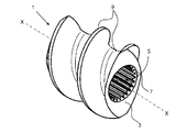
図1a及び1bは、本発明によるスクリューエレメント1の一実施形態を示したものである。スクリューエレメント1は、不図示の、同方向回転密接噛み合い型二軸押出機用に形成されている。スクリューエレメント1は、支持軸に嵌合するための内歯7を備えた、軸方向に延びる貫通孔5と、押出機能を供する外側輪郭9とを有するスクリュー本体3を含んでなる。この種の二軸押出機で使用するために、スクリューエレメント1は、別のスクリューエレメントと共に、二軸押出機の不図示の支持軸に、スクリューエレメント1の軸X−Xに沿って、軸方向に嵌合される。
1a and 1b show an embodiment of a
貫通孔5の内歯7は、有利には、(特にDIN 5480:2006又は別途ISO 4156:2005に定める)インボリュート歯形として形成されている。これにより、支持軸への大きな力の伝達が可能である。特に、内歯7は、スクリュー本体3と支持軸との間に1200N/mm2以上の力の伝達が達成されるようにして、形成されている。内歯7の形状偏差は、有利には、特に±0.01mmである。
The
スクリュー本体3の外径、特に、外側輪郭9の最大外径は58mm以下であり、好ましくは、30mm以下である。最小外径は、特に、12mmである。輪郭距離の最大偏差、すなわち、貫通孔5の内壁から外側輪郭9の表面までの距離の最大偏差は、特に、±0.05mmである。
The outer diameter of the
スクリュー本体3は、有利には、単成分材料から構成されている。この単成分材料は、特に、特に炭化物成分(炭化クロム、炭化バナジウム、炭化タングステン)の成分比の高い高強度高速度鋼又はコバルト・クロム超硬合金若しくはニッケル・クロム・モリブデン超硬合金である。スクリュー本体3の表面硬度は、(ロックウェル硬さ試験法 Cスケールに準拠して)HRC40〜HRC70の範囲、好ましくは、HRC56〜HRC70の範囲にある。これにより、押出プロセスにおける、特に、硬質充填剤及び強化材、例えばガラス繊維、グラファイト繊維、タルク等に対する高い耐摩耗性、並びに水及び酸、例えばHCl、HNO3、HSO3Cl等に対する高い耐腐食性が達成される。
The
本発明によるスクリューエレメント1の不図示の有利な実施形態において、スクリュー本体3の内部には、特に、外側輪郭9の表面又は内歯7の表面に対して均一な半径方向距離を保ち、表面の推移に追従して、軸方向に延びる少なくとも一本の内側冷却路が配置されている。冷却は、特に、20℃〜350℃の温度範囲にある。
In an advantageous embodiment, not shown, of the
有利には、外側輪郭9は、外側輪郭9の表面が軸方向に沿って、あらゆる箇所で、あるいは少なくともほぼあらゆる箇所で、同一の外側輪郭9を有する平行に配置されたスクリューエレメント1の表面に対して同一の距離を有するように、形成されている。
Advantageously, the outer contour 9 is arranged on the surface of the
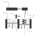
本発明によるスクリューエレメント1は、製造プラットフォーム11による生成的積層造形法の形の、以下に述べる、図2に示した本発明による方法で製造される。この方法において、金属粉末材料13は、ステップ毎にそれぞれ層をなして製造軸Z−Zの方向に重ねられて配置される。そのため、一般に、粉末材料13は、ドクター15によるか又はローラによって、製造プラットフォーム11上の全面にわたって平らにもたらされる。粉末材料13はいずれのステップに際しても、貯蔵庫としての粉末プラットフォーム17のリフトアップによって供給されて、ドクター15によって製造プラットフォーム11上に運ばれる。
The
レーザ21のレーザビーム19は、スクリューエレメント1のそれぞれの層につき、三次元モデルのデータに準拠して、所定の照射順序により、それぞれの当該層の所定の箇所で、粉末材料13を照射する。これにより、粉末材料13は部分的に完全に溶融ないし再溶融されて、直下に位置するそれぞれの層と素材的に結合される。その際、レーザビーム19によって供給されたエネルギーは、粉末材料13によって吸収され、表面全体に及ぶ還元下で、局所的に限定された焼結又は粒子の融合が生ずる。製造プラットフォーム11は、次のステップでそれぞれ次の層を生成するために、ステップ毎にわずかずつ降下される。すべての層の凝固後に、完全に安定した、三次元モデルに準拠したスクリュー本体3が得られる。生成加工は垂直方向に層毎に行なわれ、これにより、アンダカットされた輪郭も生成することが可能である。
The
本発明による方法の好ましい実施形態において、粉末材料13の形成するそれぞれの層の照射されるべき箇所は碁盤目状に一連の単位区画に分割され、レーザビーム19はそれぞれの層の種種の単位区画の照射をランダムな照射順序によって実施する。特に、照射されるべきそれぞれの層は、製造軸Z−Zに対して半径方向に周回する一連の照射ゾーンに分割され、これらの照射ゾーンを照射する順序は半径方向の内側から外側へ向かって行なわれる。これにより、製造プロセス中に、スクリュー本体3の発熱の制御を向上させることができる。
In a preferred embodiment of the method according to the invention, the area to be irradiated of each layer forming the
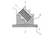
さらに、本発明による方法のさらに別の有利な実施形態において、レーザビーム19により、層をなす、スクリューエレメント1に加えて、支持構造23が溶融されるため、製造されるべきスクリューエレメント1は、製造中、粉末材料13内に支持される。有利には、支持構造23は、スクリューエレメント1の、外側輪郭9及び/又は製造プラットフォーム11を向いた端面と結合されるため、支持構造23は、融解プロセス中、発生した熱エネルギーをスクリューエレメント1から導出する。支持構造23は、特に、まず、外側輪郭9の第一の区域において、製造プラットフォームと平行に、スクリュー本体3から半径方向に離れ、その後、第二の区域において、製造軸Z−Zと平行に、製造プラットフォーム11に至るまで延びている。支持構造23は、特に、ハニカム状に形成されている。図3に示した実施形態において、スクリュー本体3は、スクリューエレメント1の軸X−Xが製造軸Z−Zと平行をなす配置で製造される。図4に示した第二の実施形態においては、スクリュー本体3は、スクリューエレメント1の軸X−Xが製造軸Z−Zと45°の夾角をなす配置で製造される。原理上、排熱の必要性に応じ、その他の角度も考えられる。これにより、製造プラットフォーム11との優れた熱的結合と、それによる、溶融後の効果的な排熱とが可能になる。これにより、特に、冷却フェーズにおける、熱に起因する材料歪みが防止される。これは、特に、内歯が優れた力の伝達を確実なものとするために重要である。
Furthermore, in yet another advantageous embodiment of the method according to the invention, in addition to the
粉末材料13は、好ましくは、特に炭化物成分(炭化クロム、炭化バナジウム、炭化タングステン)の成分比の高い粉末状の高強度高速度鋼又は粉末状のコバルト・クロム超硬合金若しくはニッケル・クロム・モリブデン超硬合金を含む。それぞれの層の層厚さは、特に20μm〜100μmの間にある。
The
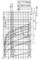
本発明による方法の有利な実施態様において、レーザビーム19のレーザエネルギー及びレーザ電源投入時間は、再溶融された状態の粉末材料13がスクリュー本体3の製造プロセスから直接硬化されるように、粉末材料13及び層厚さに合わされている。その際、硬化はDIN 17022:1994-10に準拠して行なわれる。そのため、粉末材料13の再溶融に係わるレーザパラメータは、構造部材中に発生したプロセス熱が、粉末床ないし支持構造23からなる支持構造体を経て、使用された粉末材料13にとって十分な急冷速度にて排熱されるように、選択されなければならない。必要とされる急冷速度は、使用されたそれぞれの粉末材料13に関する時間−温度−変態線図から見て取れる。
In an advantageous embodiment of the method according to the invention, the laser energy of the
図5は一例として、連続冷却、オーステナイト化温度1150℃、硬化時間10分のケースにおける、材料1.3242に関する時間−温度−変態線図を示したものである。その際、レーザパラメータと支持構造23とは、本発明により、スクリュー本体3につきHRC40〜HRC70、特に、HRC56〜HRC70の範囲の硬度までに及ぶ表面硬度上昇ないし周辺ゾーン波及硬度上昇又は深部硬度上昇が達成されるようにして、相互に適合される。その際、硬度上昇は、化学的組成の変化しない組織変態によってのみ行なわれることになる。これにより、スクリューエレメント1の補助的熱処理による補助的な硬化処理ステップは不要となる。
FIG. 5 shows, as an example, a time-temperature-transformation diagram for the material 1.3242 in the case of continuous cooling, austenitizing temperature 1150 ° C., and curing
本発明は、図で説明した実施例に限定されるものではなく、発明の主旨により機能的に等しいすべての実施形態をも含むものである。実施例はすべての特徴の組み合わせに限定されるものではなく、むしろそれぞれの個々の部分的特徴は、他のすべての部分的特徴から切り離されても、それ自体として発明上の意義を有することができる旨明確に強調しておく。さらに、本発明は、従来と同様、請求項1に定義された特徴の組み合わせに限定されるものでもなく、総じて開示されたすべての個別の特徴のうちの特定の特徴のその他のあらゆる任意の組み合わせによって定義されていてもよい。これは、基本的に、請求項1に開示された個別の特徴はいずれも実際に省かれても、あるいは本願明細書の他の箇所で開示された少なくとも一つの個別の特徴によって置き換えられてもよいことを意味している。
The present invention is not limited to the embodiments described in the drawings, but includes all embodiments that are functionally equivalent according to the gist of the invention. The embodiments are not limited to all combinations of features, but rather each individual partial feature may have its own inventive significance when separated from all other partial features. Emphasize clearly that you can. Further, the present invention is not limited to the combination of features defined in
Claims (15)
金属粉末材料(13)は、製造プラットフォーム(11)上に、ステップ毎にそれぞれ層をなして製造軸(Z−Z)の方向に重ねられて配置され、
その際、レーザビーム(19)は、前記スクリューエレメント(1)のそれぞれの層につき、三次元モデルのデータに準拠して、所定の照射順序により、それぞれの当該層の所定の箇所で、前記粉末材料(13)を照射し、
これにより、前記粉末材料(13)は部分的に完全に再溶融されて、直下に位置するそれぞれの層と素材的に結合されるため、すべての層の凝固後に、完全に安定した、三次元モデルに準拠したスクリュー本体(3)が得られることを特徴とする方法。 Comprising a screw body (3) having an axially extending through hole (5) with an internal tooth (7) for fitting on a support shaft and an outer contour (9) providing an extrusion function, in particular A method for producing a screw element (1) for a co-rotating intimately meshing twin screw extruder,
The metal powder material (13) is arranged on the production platform (11) in a layered manner for each step and stacked in the direction of the production axis (Z-Z).
At that time, the laser beam (19) is applied to each layer of the screw element (1) according to the data of the three-dimensional model according to a predetermined irradiation order at a predetermined position of each layer. Irradiate material (13),
Thereby, the powder material (13) is partly completely remelted and is materially combined with the respective layers located immediately below, so that after the solidification of all layers, a completely stable, three-dimensional A method characterized in that a screw body (3) compliant with the model is obtained.
Applications Claiming Priority (2)
| Application Number | Priority Date | Filing Date | Title |
|---|---|---|---|
| EP14171134.1A EP2952275B1 (en) | 2014-06-04 | 2014-06-04 | Screw feed element and method for the additive manufacture of screw feed elements |
| EP14171134.1 | 2014-06-04 |
Publications (1)
| Publication Number | Publication Date |
|---|---|
| JP2015229802A true JP2015229802A (en) | 2015-12-21 |
Family
ID=50897399
Family Applications (1)
| Application Number | Title | Priority Date | Filing Date |
|---|---|---|---|
| JP2015114223A Pending JP2015229802A (en) | 2014-06-04 | 2015-06-04 | Screw element and method of producing screw element |
Country Status (11)
| Country | Link |
|---|---|
| US (1) | US20150352770A1 (en) |
| EP (1) | EP2952275B1 (en) |
| JP (1) | JP2015229802A (en) |
| KR (1) | KR20150139789A (en) |
| CN (1) | CN105268974A (en) |
| DK (1) | DK2952275T3 (en) |
| ES (1) | ES2623220T3 (en) |
| HU (1) | HUE032444T2 (en) |
| PL (1) | PL2952275T3 (en) |
| PT (1) | PT2952275T (en) |
| TW (1) | TW201603925A (en) |
Cited By (2)
| Publication number | Priority date | Publication date | Assignee | Title |
|---|---|---|---|---|
| WO2018230421A1 (en) * | 2017-06-15 | 2018-12-20 | 住友電工焼結合金株式会社 | Method for manufacturing molded article, and molded article |
| JP2019157149A (en) * | 2018-03-07 | 2019-09-19 | 学校法人慶應義塾 | Laser lamination molding method and laser lamination molding device |
Families Citing this family (24)
| Publication number | Priority date | Publication date | Assignee | Title |
|---|---|---|---|---|
| FR3045442A1 (en) * | 2015-12-18 | 2017-06-23 | Michelin & Cie | MATERIAL DRIVE SCREW AND METHOD OF MANUFACTURE |
| FR3046556B1 (en) * | 2016-01-07 | 2023-11-03 | Snecma | METHOD FOR MANUFACTURING PARTS BY ADDITIVE MANUFACTURING |
| CN106180709B (en) * | 2016-07-08 | 2019-06-28 | 南京钛陶智能系统有限责任公司 | A kind of metal 3 D-printing method and its equipment |
| CN106514987B (en) * | 2016-10-24 | 2019-12-03 | 东莞市科亚新材料技术有限公司 | A kind of screw element manufacturing method of double screw extruder |
| FR3064519B1 (en) * | 2017-03-29 | 2021-02-12 | Safran Aircraft Engines | METHOD OF MANUFACTURING A METAL PART BY ADDITIVE MANUFACTURING |
| EP3417961B1 (en) * | 2017-06-19 | 2022-07-27 | General Electric Company | Additive manufacturing fixture |
| EP3632658A1 (en) * | 2017-10-04 | 2020-04-08 | CL Schutzrechtsverwaltungs GmbH | Method for operating at least one apparatus for additively manufacturing three-dimensional objects |
| WO2019089764A1 (en) | 2017-10-31 | 2019-05-09 | Aeroprobe Corporation | Solid-state additive manufacturing system and material compositions and structures |
| US10933492B2 (en) * | 2017-11-29 | 2021-03-02 | Lincoln Global, Inc. | Systems and methods of additive structural build techniques |
| US11229953B2 (en) | 2017-11-29 | 2022-01-25 | Lincoln Global, Inc. | Methods and systems for additive manufacturing |
| CN107900338B (en) * | 2017-12-05 | 2020-09-15 | 北京星航机电装备有限公司 | Fine structure frock is made to complex based on 3D prints |
| CN108247063A (en) * | 2018-01-29 | 2018-07-06 | 北京汇越新材料科技有限公司 | A kind of composite bimetal pipe material preparation method based on heat and other static pressuring processes |
| USD929799S1 (en) * | 2018-05-04 | 2021-09-07 | Buss Ag | Screw shaft element |
| USD961990S1 (en) * | 2018-05-04 | 2022-08-30 | Buss Ag | Screw shaft element |
| DE202018104142U1 (en) * | 2018-07-18 | 2019-10-22 | Vogelsang Gmbh & Co. Kg | Rotor for an eccentric screw pump |
| CN108950540A (en) * | 2018-07-24 | 2018-12-07 | 亚琛联合科技(天津)有限公司 | A kind of combined machining method of ultrahigh speed laser melting coating and surface remelting |
| US11167375B2 (en) | 2018-08-10 | 2021-11-09 | The Research Foundation For The State University Of New York | Additive manufacturing processes and additively manufactured products |
| AU2020208099A1 (en) * | 2019-01-18 | 2021-06-24 | Vbn Components Ab | 3D printed high carbon content steel and method of preparing the same |
| JP2022544565A (en) * | 2019-08-14 | 2022-10-19 | エンテック マニュファクチャリング エルエルシー | Additively manufactured extruder components |
| JP2023515548A (en) * | 2020-02-24 | 2023-04-13 | カーボン ホールディングス インテレクチュアル プロパティズ, エルエルシー | Systems and methods for producing high melting point hydrocarbons from coal |
| CN111299581B (en) * | 2020-03-30 | 2021-08-03 | 成都飞机工业(集团)有限责任公司 | Method for improving success rate of 3D printing of thin-wall metal component |
| CN112555268B (en) * | 2020-11-10 | 2021-09-21 | 中广核研究院有限公司 | Flexible shaft for transmitting signals of nuclear power station fingerstall tube core stacking and preparation method thereof |
| CN115194179A (en) * | 2021-04-12 | 2022-10-18 | 中国航发商用航空发动机有限责任公司 | Support structure and method for manufacturing spiral pipeline |
| DE102022127575A1 (en) * | 2022-10-19 | 2024-04-25 | Battenfeld-Cincinnati Germany Gmbh | Additively manufactured components of an extruder |
Family Cites Families (19)
| Publication number | Priority date | Publication date | Assignee | Title |
|---|---|---|---|---|
| ATE138294T1 (en) * | 1986-10-17 | 1996-06-15 | Univ Texas | METHOD AND DEVICE FOR PRODUCING SINTERED MOLDED BODIES BY PARTIAL INTERNATION |
| JP2792732B2 (en) | 1990-11-09 | 1998-09-03 | 三菱重工業株式会社 | Screw for split type extruder |
| DE10013474A1 (en) * | 2000-03-18 | 2001-09-20 | Automatisierte Produktionstech | Tempering system for e.g. extrusion screws under high thermal- and mechanical stresses, comprises internal channels for tempering medium, close to component contours |
| US7097442B2 (en) | 2001-11-30 | 2006-08-29 | Kohei Sawa | Extruder |
| DE10260893A1 (en) * | 2002-12-17 | 2004-07-15 | W. Haldenwanger Technische Keramik Gmbh & Co Kg | Screw conveyor for conveying bulk goods at elevated temperatures |
| DE10338180B3 (en) | 2003-08-17 | 2005-04-28 | Erich Roos | Extruder screw manufacture involves assembling a stack of contored metal plates with spacers between on a screw shaft |
| JP4083183B2 (en) | 2005-06-27 | 2008-04-30 | 株式会社日本製鋼所 | Screw for kneading extruder |
| EP1992709B1 (en) | 2007-05-14 | 2021-09-15 | EOS GmbH Electro Optical Systems | Metal powder for use in additive manufacturing method for the production of three-dimensional objects and method using such metal powder |
| DE102007048385B3 (en) * | 2007-10-09 | 2009-01-29 | Fraunhofer-Gesellschaft zur Förderung der angewandten Forschung e.V. | Production of components using generative processes, especially fused deposition modeling, comprises forming grid around component which is gripped to manipulate component, without direct contact with component itself |
| GB0719747D0 (en) | 2007-10-10 | 2007-11-21 | Materialise Nv | Method and apparatus for automatic support generation for an object made by means of a rapid prototype production method |
| DE102008029304A1 (en) * | 2008-06-20 | 2009-12-24 | Bayer Technology Services Gmbh | Method for producing screw elements |
| WO2011006516A1 (en) | 2009-07-16 | 2011-01-20 | Blach Josef A | Extruder |
| ES2402255T5 (en) | 2010-02-26 | 2020-05-29 | Vbn Components Ab | Metallic multiphase material and manufacturing methods for it |
| US8595910B2 (en) * | 2010-06-23 | 2013-12-03 | Entek Manufacturing Llc | Restoration of worn metallic extrusion processing elements |
| DE102011112148B4 (en) | 2011-09-01 | 2015-12-24 | Kraussmaffei Berstorff Gmbh | Extruder and process for producing an extruder |
| CH705750A1 (en) * | 2011-10-31 | 2013-05-15 | Alstom Technology Ltd | A process for the production of components or portions, which consist of a high-temperature superalloy. |
| CN102430711A (en) * | 2011-12-31 | 2012-05-02 | 中国兵器工业集团第七0研究所 | Rapid manufacturing method of booster turbine impeller |
| US10207423B2 (en) * | 2012-02-28 | 2019-02-19 | Steer Engineering Private Limited | Extruder mixing element for a co-rotating twin screw extruder |
| GB201209415D0 (en) | 2012-05-28 | 2012-07-11 | Renishaw Plc | Manufacture of metal articles |
-
2014
- 2014-06-04 HU HUE14171134A patent/HUE032444T2/en unknown
- 2014-06-04 EP EP14171134.1A patent/EP2952275B1/en not_active Revoked
- 2014-06-04 DK DK14171134.1T patent/DK2952275T3/en active
- 2014-06-04 PT PT141711341T patent/PT2952275T/en unknown
- 2014-06-04 ES ES14171134.1T patent/ES2623220T3/en active Active
- 2014-06-04 PL PL14171134T patent/PL2952275T3/en unknown
-
2015
- 2015-05-14 TW TW104115370A patent/TW201603925A/en unknown
- 2015-05-19 CN CN201510257554.4A patent/CN105268974A/en active Pending
- 2015-06-02 KR KR1020150077920A patent/KR20150139789A/en unknown
- 2015-06-03 US US14/729,852 patent/US20150352770A1/en not_active Abandoned
- 2015-06-04 JP JP2015114223A patent/JP2015229802A/en active Pending
Cited By (8)
| Publication number | Priority date | Publication date | Assignee | Title |
|---|---|---|---|---|
| WO2018230421A1 (en) * | 2017-06-15 | 2018-12-20 | 住友電工焼結合金株式会社 | Method for manufacturing molded article, and molded article |
| CN109963671A (en) * | 2017-06-15 | 2019-07-02 | 住友电工烧结合金株式会社 | Manufacture the method and model articles of model articles |
| JPWO2018230421A1 (en) * | 2017-06-15 | 2020-04-16 | 住友電工焼結合金株式会社 | Manufacturing method of molded article, and molded article |
| JP7029623B2 (en) | 2017-06-15 | 2022-03-04 | 住友電工焼結合金株式会社 | Manufacturing method of modeled object and modeled object |
| CN109963671B (en) * | 2017-06-15 | 2022-03-08 | 住友电工烧结合金株式会社 | Method for producing molded article and molded article |
| US11331850B2 (en) | 2017-06-15 | 2022-05-17 | Sumitomo Electric Sintered Alloy, Ltd. | Method for manufacturing shaped article, and shaped article |
| JP2019157149A (en) * | 2018-03-07 | 2019-09-19 | 学校法人慶應義塾 | Laser lamination molding method and laser lamination molding device |
| JP7066131B2 (en) | 2018-03-07 | 2022-05-13 | 慶應義塾 | Laser laminated modeling method and laser laminated modeling equipment |
Also Published As
| Publication number | Publication date |
|---|---|
| HUE032444T2 (en) | 2017-09-28 |
| PT2952275T (en) | 2017-05-03 |
| US20150352770A1 (en) | 2015-12-10 |
| KR20150139789A (en) | 2015-12-14 |
| CN105268974A (en) | 2016-01-27 |
| PL2952275T3 (en) | 2017-05-31 |
| TW201603925A (en) | 2016-02-01 |
| EP2952275A1 (en) | 2015-12-09 |
| EP2952275B1 (en) | 2017-01-25 |
| DK2952275T3 (en) | 2017-04-24 |
| ES2623220T3 (en) | 2017-07-10 |
Similar Documents
| Publication | Publication Date | Title |
|---|---|---|
| JP2015229802A (en) | Screw element and method of producing screw element | |
| Gadagi et al. | A review on advances in 3D metal printing | |
| US8979971B2 (en) | Process for producing metallic components | |
| Capello et al. | Repairing of sintered tools using laser cladding by wire | |
| Yung et al. | Laser polishing of additive manufactured tool steel components using pulsed or continuous-wave lasers | |
| JP5602913B2 (en) | Manufacturing method of three-dimensional shaped object and three-dimensional shaped object obtained therefrom | |
| US20180221958A1 (en) | Parts and methods for producing parts using hybrid additive manufacturing techniques | |
| L. Amorim et al. | Selective laser sintering of Mo-CuNi composite to be used as EDM electrode | |
| JP5337545B2 (en) | Manufacturing method of three-dimensional shaped object and three-dimensional shaped object obtained therefrom | |
| JP2007508145A (en) | Method for welding by plasma, laser or electron beam by using copper or copper alloy as filler material between the same materials which tend to cause excessive curing or different materials | |
| CN205868388U (en) | Extrusion roller shell | |
| CN106040347A (en) | Squeezing roller sleeve and manufacturing method thereof | |
| US20210107060A1 (en) | Multi-material tooling and methods of making same | |
| JP2022544565A (en) | Additively manufactured extruder components | |
| US20180236532A1 (en) | Three-dimensional printed tooling for high pressure die cast tooling | |
| US11701707B2 (en) | Components having low aspect ratio | |
| Ghosh et al. | Selective laser sintering: a case study of tungsten carbide and cobalt powder sintering by pulsed Nd: YAG laser | |
| Furumoto et al. | Improving surface quality using laser scanning and machining strategy combining powder bed fusion and machining processes | |
| CN105798294A (en) | Rapid part prototyping method for refractory materials | |
| Sibisi et al. | LAM additive manufacturing: A fundamental review on mechanical properties, common defects, dominant processing variables, and its applications | |
| JP2017529455A (en) | Anvil for rotary cutting unit that is layered | |
| US20180043434A1 (en) | Method of forming a component | |
| JP2002210358A (en) | Housing for plastic, metal powder, ceramic powder or food processing machines | |
| Kumar et al. | Advantage | |
| Parchegani et al. | Laser welding of additively manufactured parts-A review |