JP2015223902A - Saddle riding type vehicle - Google Patents
Saddle riding type vehicle Download PDFInfo
- Publication number
- JP2015223902A JP2015223902A JP2014108811A JP2014108811A JP2015223902A JP 2015223902 A JP2015223902 A JP 2015223902A JP 2014108811 A JP2014108811 A JP 2014108811A JP 2014108811 A JP2014108811 A JP 2014108811A JP 2015223902 A JP2015223902 A JP 2015223902A
- Authority
- JP
- Japan
- Prior art keywords
- wall
- opening
- seat frame
- disposed
- side wall
- Prior art date
- Legal status (The legal status is an assumption and is not a legal conclusion. Google has not performed a legal analysis and makes no representation as to the accuracy of the status listed.)
- Pending
Links
Images


Classifications
-
- B—PERFORMING OPERATIONS; TRANSPORTING
- B62—LAND VEHICLES FOR TRAVELLING OTHERWISE THAN ON RAILS
- B62J—CYCLE SADDLES OR SEATS; AUXILIARY DEVICES OR ACCESSORIES SPECIALLY ADAPTED TO CYCLES AND NOT OTHERWISE PROVIDED FOR, e.g. ARTICLE CARRIERS OR CYCLE PROTECTORS
- B62J15/00—Mud-guards for wheels
-
- B—PERFORMING OPERATIONS; TRANSPORTING
- B62—LAND VEHICLES FOR TRAVELLING OTHERWISE THAN ON RAILS
- B62J—CYCLE SADDLES OR SEATS; AUXILIARY DEVICES OR ACCESSORIES SPECIALLY ADAPTED TO CYCLES AND NOT OTHERWISE PROVIDED FOR, e.g. ARTICLE CARRIERS OR CYCLE PROTECTORS
- B62J11/00—Supporting arrangements specially adapted for fastening specific devices to cycles, e.g. supports for attaching maps
- B62J11/10—Supporting arrangements specially adapted for fastening specific devices to cycles, e.g. supports for attaching maps for mechanical cables, hoses, pipes or electric wires, e.g. cable guides
- B62J11/19—Supporting arrangements specially adapted for fastening specific devices to cycles, e.g. supports for attaching maps for mechanical cables, hoses, pipes or electric wires, e.g. cable guides specially adapted for electric wires
-
- B—PERFORMING OPERATIONS; TRANSPORTING
- B62—LAND VEHICLES FOR TRAVELLING OTHERWISE THAN ON RAILS
- B62J—CYCLE SADDLES OR SEATS; AUXILIARY DEVICES OR ACCESSORIES SPECIALLY ADAPTED TO CYCLES AND NOT OTHERWISE PROVIDED FOR, e.g. ARTICLE CARRIERS OR CYCLE PROTECTORS
- B62J15/00—Mud-guards for wheels
- B62J15/02—Fastening means; Stays
Abstract
Description
本発明は、鞍乗型車両に関する。 The present invention relates to a saddle riding type vehicle.
従来から、鞍乗型車両は、リアフェンダとマッドガードとを備えている。リアフェンダおよびマッドガードは、後輪の上方に設けられている。リアフェンダおよびマッドガードは、鞍乗型車両の走行中の後輪からの水はねや泥はねを防止するために、後輪を覆うように配置されている。 Conventionally, a saddle-ride type vehicle has a rear fender and a mudguard. The rear fender and the mudguard are provided above the rear wheel. The rear fender and the mudguard are arranged so as to cover the rear wheels in order to prevent water splashes and mud splashes from the rear wheels while the saddle riding type vehicle is traveling.
特許文献1には、リアフェンダとマッドガードとを一体に成形したものを備えた鞍乗型車両が開示されている。鞍乗型車両の軽量化の観点から、リアフェンダおよびマッドガードは、樹脂材料で形成されている。 Patent Document 1 discloses a straddle-type vehicle provided with a rear fender and a mud guard integrally formed. From the viewpoint of weight reduction of the saddle riding type vehicle, the rear fender and the mudguard are made of a resin material.
ところで、特許文献1の鞍乗型車両では、その後部にフラッシャライトが配置されている。このため、フラッシャライトよりも前方においてマッドガードをリアフェンダに接続する必要がある。フラッシャライトの取付位置によっては、マッドガードの車両前後方向の長さを長くせざるをえない。マッドガードは樹脂材料によって形成されているため、マッドガードの車両前後方向の長さが長くなると、マッドガードの剛性が足りないという問題がある。 By the way, in the saddle riding type vehicle of Patent Document 1, a flasher light is arranged at the rear part thereof. For this reason, it is necessary to connect the mudguard to the rear fender in front of the flasher light. Depending on the mounting position of the flasher light, the length of the mudguard in the vehicle front-rear direction must be increased. Since the mudguard is formed of a resin material, there is a problem that the rigidity of the mudguard is insufficient when the length of the mudguard in the vehicle front-rear direction is increased.
本発明はかかる点に鑑みてなされたものであり、その目的は、泥除け性能を確保すると共に、マッドガードの剛性が確保された鞍乗型車両を提供することである。 This invention is made | formed in view of this point, The objective is to provide the straddle-type vehicle with which the mudguard performance was ensured and the rigidity of the mudguard was ensured.
マッドガードの剛性を確保するために、マッドガードとリアフェンダとを別体に成形し、リアフェンダとマッドガードとの間に剛性の高い金属製の連結部材を配置することが考えられる。ここで、連結部材は、樹脂材料よりも剛性は高いが、樹脂材料より重いため、鞍乗型車両の軽量化のためには小型のものを用いることが好ましい。また、連結部材は、剛性を考慮すると断面形状がU字状に形成されたものが好ましい。しかし、連結部材が小型かつその断面形状がU字状の場合、後輪からの水はねや泥はねを連結部材において効果的に防止できず、連結部材の周辺から上方に巻き上がるという問題がある。本願発明は、上記知見に基づいて創作されたものである。 In order to ensure the rigidity of the mudguard, it is conceivable to form the mudguard and the rear fender separately and to dispose a highly rigid metal connecting member between the rear fender and the mudguard. Here, although the rigidity of the connecting member is higher than that of the resin material, it is heavier than the resin material. Therefore, it is preferable to use a small member for reducing the weight of the saddle riding type vehicle. The connecting member preferably has a U-shaped cross section when rigidity is taken into consideration. However, when the connecting member is small and the cross-sectional shape is U-shaped, water splash and mud splash from the rear wheel cannot be effectively prevented in the connecting member, and the problem is that the connecting member rolls upward from the periphery of the connecting member There is. The present invention has been created based on the above findings.
本発明に係る鞍乗型車両は、メインフレームと、前記メインフレームから後方に延びる左シートフレームと、前記メインフレームから後方に延び、前記左シートフレームの右方に配置された右シートフレームと、前記左シートフレームおよび前記右シートフレームより後方に配置されたテールライトと、前記テールライトより前方に配置された左リアフラッシャーおよび右リアフラッシャーと、前記左シートフレームおよび前記右シートフレームの下方に配置された後輪と、前記左シートフレームおよび前記右シートフレームの下方かつ前記後輪の一部の上方に配置されたリアフェンダと、前記テールライトの下方に配置され、前記左リアフラッシャーおよび前記右リアフラッシャーより前方において前記左シートフレームおよび前記右シートフレームに連結され、前記左シートフレームおよび前記右シートフレームから後方に延びる金属製の連結部材と、前記連結部材に連結され、前記連結部材から後斜め下方に延び、その後端が前記後輪より後方に配置されたマッドガードと、を備え、前記連結部材は、車両平面視で、前記後輪と重なる第1上壁と、前記第1上壁の左端から左斜め下方に延び、第1開口が形成された第1左側壁と、前記第1上壁の右端から右斜め下方に延び、第2開口が形成された第1右側壁と、を備え、前記第1開口および前記第2開口は、前記連結部材より軽い樹脂材料から成形された板状部材によってそれぞれ覆われている。 A straddle-type vehicle according to the present invention includes a main frame, a left seat frame extending rearward from the main frame, a right seat frame extending rearward from the main frame and disposed on the right side of the left seat frame, A taillight disposed behind the left seat frame and the right seat frame, a left rear flasher and a right rear flasher disposed forward of the taillight, and disposed below the left seat frame and the right seat frame. A rear fender, a rear fender disposed below the left seat frame and the right seat frame and above a part of the rear wheel, and disposed below the taillight, the left rear flasher and the right rear The left seat frame and the right seat in front of the flasher A metal connecting member connected to the frame and extending rearward from the left seat frame and the right seat frame, connected to the connecting member, extending rearward and obliquely downward from the connecting member, and a rear end behind the rear wheel The connecting member includes a first upper wall that overlaps with the rear wheel in a plan view of the vehicle, and extends obliquely to the left from the left end of the first upper wall to form a first opening. A first left side wall, and a first right side wall extending obliquely downward and right from the right end of the first upper wall and having a second opening formed thereon, wherein the first opening and the second opening are Each is covered with a plate-like member molded from a resin material lighter than the connecting member.
本発明に係る鞍乗型車両では、連結部材は、左リアフラッシャーおよび右リアフラッシャーより前方において左シートフレームおよび右シートフレームに連結している。このため、連結部材と左右シートフレームとの連結位置からマッドガードの後端の位置までが比較的長くなる。しかし、剛性の高い連結部材が左右のシートフレームとマッドガードとを連結しているため、リアフェンダとマッドガードとを一体に成形した場合と比較して、マッドガードの車両前後方向の長さは短くなり、剛性は高くなる。また、連結部材の第1左側壁および第1右側壁はそれぞれ斜め下方に延びている。このため、第1左側壁および第1右側壁が単に下方に延びる場合、すなわち連結部材の断面形状がU字状の場合と比較して、連結部材が同じ重量であっても連結部材の車幅方向の長さが長くなる。この結果、連結部材における泥除け性能が向上する。また、連結部材には、鞍乗型車両の軽量化のために第1開口および第2開口が形成されているが、第1開口および第2開口は、軽量な樹脂材料製の板状部材に覆われている。このため、連結部材の第1右側壁および第1左側壁が斜め下方に延びている場合であっても、後輪から巻き上げられた泥等が第1開口および第2開口を介してテールライトや乗員に当たることを防止することができる。 In the saddle riding type vehicle according to the present invention, the connecting member is connected to the left seat frame and the right seat frame in front of the left rear flasher and the right rear flasher. For this reason, the position from the connecting position of the connecting member and the left and right seat frames to the position of the rear end of the mudguard is relatively long. However, because the highly rigid connecting member connects the left and right seat frames and the mudguard, the length of the mudguard in the longitudinal direction of the vehicle is shorter and rigid compared to the case where the rear fender and the mudguard are molded integrally. Becomes higher. The first left side wall and the first right side wall of the connecting member extend obliquely downward. For this reason, compared with the case where the first left side wall and the first right side wall simply extend downward, that is, when the cross-sectional shape of the connecting member is U-shaped, the vehicle width of the connecting member is the same. The length of the direction becomes longer. As a result, the mudguard performance in the connecting member is improved. In addition, the first opening and the second opening are formed in the connecting member in order to reduce the weight of the saddle riding type vehicle. However, the first opening and the second opening are formed on a lightweight plate member made of a resin material. Covered. For this reason, even when the first right side wall and the first left side wall of the connecting member extend obliquely downward, mud or the like wound up from the rear wheel can be taillighted through the first opening and the second opening. It can prevent hitting a passenger.
本発明の一態様によれば、前記板状部材と前記マッドガードとは一体に成形されている。 According to one aspect of the present invention, the plate-like member and the mud guard are integrally formed.
上記態様によれば、板状部材とマッドガードとを接続する部品を削減することができると共に、部品の削減による軽量化が実現される。 According to the said aspect, while reducing the component which connects a plate-shaped member and a mud guard, the weight reduction by reduction of components is implement | achieved.
本発明の一態様によれば、前記連結部材は、第1左係合部を有し、前記第1左側壁から左方に延びる第1左壁と、第1右係合部を有し、前記第1右側壁から右方に延びる第1右壁と、を備え、前記マッドガードは、前記第1左係合部と係合する第2左係合部を有する第2左壁と、前記第1右係合部と係合する第2右係合部を有する第2右壁と、を備え、前記板状部材は、前記第1上壁に対向する位置に配置される第2上壁と、前記第2上壁の左端から左斜め下方に延び、前記第1開口を覆う第2左側壁と、前記第2上壁の右端から右斜め下方に延び、前記第2開口を覆う第2右側壁と、を備え、前記連結部材の前記第1上壁および前記板状部材の前記第2上壁は、前記第2左壁と前記第2右壁との間に配置され、前記連結部材の第1上壁の下面は、前記板状部材の前記第2上壁の上面に対向し、前記第1左壁の上面および前記第1右壁の上面は、それぞれ、前記第2左壁の下面および前記第2右壁の下面に対向する。 According to an aspect of the present invention, the connecting member has a first left engaging portion, a first left wall extending leftward from the first left side wall, and a first right engaging portion, A first right wall extending rightward from the first right side wall, and the mudguard has a second left wall having a second left engagement portion that engages with the first left engagement portion, A second right wall having a second right engagement portion that engages with the first right engagement portion, and the plate-like member is disposed at a position facing the first upper wall; A second left side wall extending obliquely to the left from the left end of the second upper wall and covering the first opening; and a second right side extending obliquely downward to the right from the right end of the second upper wall and covering the second opening. A wall, and the first upper wall of the connecting member and the second upper wall of the plate-like member are disposed between the second left wall and the second right wall, Below the first upper wall Is opposed to the upper surface of the second upper wall of the plate-like member, and the upper surface of the first left wall and the upper surface of the first right wall are the lower surface of the second left wall and the second right wall, respectively. Opposite to the bottom surface.
上記態様によれば、連結部材とマッドガードとをより確実に連結することができる。 According to the said aspect, a connection member and a mud guard can be connected more reliably.
本発明の一態様によれば、前記第1左側壁は、前記第1開口が形成された第1左部分と、前記第1左部分より後方に位置し、車幅方向の寸法が前記第1左部分の車幅方向の寸法より小さい第2左部分と、を備え、前記第2左壁は、前記第1左側壁の前記第2左部分の左方に配置され、前記第1右側壁は、前記第2開口が形成された第1右部分と、前記第1右部分より後方に位置し、車幅方向の寸法が前記第1右部分の車幅方向の寸法より小さい第2右部分と、を備え、前記第2右壁は、前記第1右側壁の前記第2右部分の右方に配置されている。 According to an aspect of the present invention, the first left side wall is positioned behind the first left portion in which the first opening is formed and the first left portion, and the dimension in the vehicle width direction is the first left side portion. A second left portion that is smaller than the dimension of the left portion in the vehicle width direction, and the second left wall is disposed to the left of the second left portion of the first left side wall, and the first right side wall is A first right portion in which the second opening is formed, and a second right portion that is located rearward of the first right portion and that is smaller in the vehicle width direction than the first right portion. The second right wall is disposed to the right of the second right portion of the first right side wall.
上記態様によれば、第1左側壁の第2左部分の左方には第2左壁が配置されているため、第2左部分の車幅方向の寸法を第1左部分の車幅方向の寸法より小さくしても、後輪から巻き上げられた泥等は第2左壁において防ぐことができる。また、第1右側壁の第2右部分の右方には第2右壁が配置されているため、第2右部分の車幅方向の寸法を第1右部分の車幅方向の寸法より小さくしても、後輪から巻き上げられた泥等は第2右壁において防ぐことができる。この結果、連結部材を小型化することができ、軽量化が実現される。 According to the above aspect, since the second left wall is disposed to the left of the second left portion of the first left side wall, the dimension of the second left portion in the vehicle width direction is set to the vehicle width direction of the first left portion. Even if the size is smaller than the size, mud wound up from the rear wheel can be prevented in the second left wall. Further, since the second right wall is disposed on the right side of the second right portion of the first right side wall, the dimension in the vehicle width direction of the second right portion is smaller than the dimension in the vehicle width direction of the first right portion. Even so, mud or the like wound from the rear wheel can be prevented on the second right wall. As a result, the connecting member can be reduced in size and light weight can be realized.
本発明の一態様によれば、前記第1左部分の車両上下方向の寸法は、前記第2左部分の車両上下方向の寸法より大きく、前記第1右部分の車両上下方向の寸法は、前記第2右部分の車両上下方向の寸法より大きい。 According to an aspect of the present invention, the vehicle vertical dimension of the first left portion is greater than the vehicle vertical dimension of the second left portion, and the vehicle vertical dimension of the first right portion is It is larger than the vehicle vertical dimension of the second right portion.
上記態様によれば、連結部材の剛性を確保しつつ、連結部材自体の軽量化を実現することができる。 According to the said aspect, weight reduction of connection member itself is realizable, ensuring the rigidity of a connection member.
本発明の一態様によれば、前記テールライトの前方に配置されたバッテリと、前記マッドガードに配置され、ライセンスプレートを取り付け可能な取付部と、前記取付部の上方に配置され、前記ライセンスプレートが前記取付部に取り付けられたとき、前記ライセンスプレートに光を照射するプレート用ライトと、前記バッテリおよび前記プレート用ライトに接続されたケーブルと、を備え、前記板状部材は、前記第2上壁の下方に配置され、車両前後方向に延びる第2下壁、を備え、前記ケーブルは、前記第2下壁の上に配置されている。 According to an aspect of the present invention, a battery disposed in front of the taillight, a mounting portion disposed on the mudguard, to which a license plate can be attached, and disposed above the mounting portion, A plate light for irradiating the license plate with light when attached to the attachment portion; and a cable connected to the battery and the plate light, wherein the plate-like member is the second upper wall. And a second lower wall extending in the vehicle front-rear direction, and the cable is disposed on the second lower wall.
上記態様によれば、ケーブルの下方には第2下壁が配置されているため、後輪から巻き上がる泥や石等がケーブルに当たることを防止することができる。 According to the said aspect, since the 2nd lower wall is arrange | positioned under the cable, it can prevent that the mud, stone, etc. which roll up from a rear wheel hit a cable.
本発明の一態様によれば、車両背面視で、前記第1左側壁の左端は、前記後輪の左端より左方に位置し、前記第1右側壁の右端は、前記後輪の右端より右方に位置する。 According to one aspect of the present invention, the left end of the first left side wall is located to the left of the left end of the rear wheel in the rear view of the vehicle, and the right end of the first right side wall is from the right end of the rear wheel. Located on the right side.
上記態様によれば、連結部材が車幅方向に大きく広がっているため、連結部材における泥除け性能が向上する。 According to the said aspect, since the connection member has spread widely in the vehicle width direction, the mudguard performance in a connection member improves.
本発明の一態様によれば、前記左シートフレームおよび前記右シートフレームの上方に配置されたシートを備え、前記第1開口および前記第2開口は、車両前後方向に延び、前記第1開口の前縁および前記第2開口の前縁は、前記シートの後端より前方に位置し、前記第1開口の後縁および前記第2開口の後縁は、前記テールライトの前後方向の中間点より後方に位置する。 According to an aspect of the present invention, the seat includes a seat disposed above the left seat frame and the right seat frame, and the first opening and the second opening extend in a vehicle front-rear direction, and the first opening A front edge and a front edge of the second opening are located in front of a rear end of the seat, and a rear edge of the first opening and a rear edge of the second opening are from an intermediate point in the front-rear direction of the taillight. Located behind.
上記態様によれば、第1開口および第2開口が大きく形成されているため、連結部材の軽量化が実現される。 According to the said aspect, since the 1st opening and the 2nd opening are formed large, weight reduction of a connection member is implement | achieved.
以上のように、本発明によれば、泥除け性能を確保すると共に、マッドガードの剛性が確保された鞍乗型車両を提供することができる。 As described above, according to the present invention, it is possible to provide a straddle-type vehicle in which mudguard performance is secured and the rigidity of the mudguard is secured.
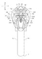
以下、本発明の実施形態について説明する。図1に示すように、本実施形態に係る自動二輪車1は、アンダーボーン型の自動二輪車1である。なお、本発明に係る自動二輪車はアンダーボーン型の自動二輪車1に限定される訳ではない。本発明に係る自動二輪車は、いわゆるモペット型、オンロード型、オフロード型、またはスクータ型等の他の型式の自動二輪車であってもよい。 Hereinafter, embodiments of the present invention will be described. As shown in FIG. 1, a motorcycle 1 according to this embodiment is an underbone type motorcycle 1. The motorcycle according to the present invention is not limited to the underbone type motorcycle 1. The motorcycle according to the present invention may be another type of motorcycle such as a so-called moped type, on-road type, off-road type, or scooter type.
以下の説明において、特に断らない限り、前、後、左、右、上、下は、それぞれ自動二輪車1のシート10に着座した乗員から見た前、後、左、右、上、下を意味するものとする。上、下は、それぞれ自動二輪車1が水平面上に停止しているときの鉛直方向の上、下を意味するものとする。図面に付した符号F、Re、L、R、Up,Dnは、それぞれ前、後、左、右、上、下を表す。
In the following description, unless otherwise specified, front, rear, left, right, upper, and lower mean front, rear, left, right, upper, and lower as viewed from the occupant seated on the
図1に示すように、自動二輪車1は、ヘッドパイプ20と、ヘッドパイプ20に接続された車体フレーム30と、乗員が着座するシート10と、内燃機関であるエンジン15と、を備えている。ヘッドパイプ20には、ステアリングシャフト(図示せず)が支持されている。ステアリングシャフトの上部にはハンドル24が設けられている。ステアリングシャフトの下部にはフロントフォーク26が設けられている。フロントフォーク26の下端部には、前輪5が回転自在に支持されている。
As shown in FIG. 1, the motorcycle 1 includes a
図1に示すように、車体フレーム30は、メインフレーム32と、左シートフレーム40Lと、右シートフレーム40Rと、左ダウンフレーム50Lと、右ダウンフレーム50Rと、左バックステー56Lと、右バックステー56Rと、を備えている。
As shown in FIG. 1, the
図1に示すように、自動二輪車1は、車体カバー28を備えている。車体カバー28は、左シートフレーム40Lおよび右シートフレーム40Rの少なくとも側方に配置されている。車体カバー28は、ヘッドパイプ20の側方に配置されている。車体カバー28は、メインフレーム32の側方に配置されている。車体カバー28は、左シートフレーム40Lおよび右シートフレーム40Rの側方に配置されている。車体カバー28は、ヘッドパイプ20の後方かつシート10の前方においてシート10より下方の位置まで後斜め下方に延びる上面部28Uを備えている。車体カバー28は、車両側面視で下方に凹む凹部29を備えている。凹部29は、ヘッドパイプ20の後方に形成されている。凹部29は、シート10の前方に形成されている。凹部29は、シート10より下方に形成されている。凹部29は、エンジン15の上方に形成されている。車体カバー28が凹部29を備えていることによって、ヘッドパイプ20とシート10との間には空間が形成されている。
As shown in FIG. 1, the motorcycle 1 includes a
図1に示すように、エンジン15は、メインフレーム32の下方に配置されている。エンジン15は、メインフレーム32に支持されている。エンジン15は、左ダウンフレーム50Lおよび右ダウンフレーム50Rに設けられたエンジンブラケット55に支持されている。
As shown in FIG. 1, the
図1に示すように、メインフレーム32は、ヘッドパイプ20に接続されている。メインフレーム32は、ヘッドパイプ20から後斜め下方に延びている。
As shown in FIG. 1, the
図1に示すように、左シートフレーム40Lは、メインフレーム32に接続されている。左シートフレーム40Lは、メインフレーム32から後方に延びる。左シートフレーム40Lは、左第1部分41Lと、左第2部分42Lとを備えている。左第1部分41Lと左第2部分42Lとは一体に形成されている。左第1部分41Lは、メインフレーム32から後斜め下方に延びる。左第2部分42Lは、左第1部分41Lから後斜め上方に延びる。
As shown in FIG. 1, the left seat frame 40 </ b> L is connected to the
図1に示すように、右シートフレーム40Rは、メインフレーム32に接続されている。左シートフレーム40Lは、メインフレーム32から後方に延びる。右シートフレーム40Rは、左シートフレーム40Lの右方に配置されている。右シートフレーム40Rは、右第1部分41Rと、右第2部分42Rとを備えている。右第1部分41Rと右第2部分42Rとは一体に形成されている。右第1部分41Rは、メインフレーム32から後斜め下方に延びる。右第2部分42Rは、右第1部分41Rから後斜め上方に延びる。
As shown in FIG. 1, the right seat frame 40 </ b> R is connected to the
図1に示すように、左ダウンフレーム50Lは、左シートフレーム40Lの左第1部分41Lに接続されている。左ダウンフレーム50Lは、左シートフレーム40Lから後斜め下方に延びる。
As shown in FIG. 1, the left down
図1に示すように、右ダウンフレーム50Rは、右シートフレーム40Rの左第1部分41Rに接続されている。右ダウンフレーム50Rは、右シートフレーム40Rから後斜め下方に延びる。右ダウンフレーム50Rは、左ダウンフレーム50Lの右方に位置する。
As shown in FIG. 1, the right down
図1に示すように、自動二輪車1は、エンジンブラケット55に連結されたリアアーム58を備えている。エンジンブラケット55とリアアーム58とは、ピポット軸59を介して連結されている。リアアーム58は、エンジンブラケット55に揺動自在に連結されている。リアアーム58は、車体フレーム30あるいはエンジン15に揺動自在に連結されていてもよい。
As shown in FIG. 1, the motorcycle 1 includes a
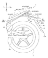
図2に示すように、自動二輪車1は、後輪7を備えている。後輪7は、リアアーム58の後端部に回転自在に支持されている。図3に示すように、後輪7は、左シートフレーム40Lおよび右シートフレーム40Rの下方に配置されている。なお、図3において、説明の便宜上、車体カバー28およびシート10の図示を省略している。
As shown in FIG. 2, the motorcycle 1 includes a
図1に示すように、シート10は、左シートフレーム40Lおよび右シートフレーム40Rの上方に配置されている。シート10は、左シートフレーム40Lおよび右シートフレーム40Rに支持されている。
As shown in FIG. 1, the
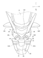
図2に示すように、車体カバー28には、グラブバー18が設けられている。グラブバー18の後端18RRは、シート10Rより後方に位置する。グラブバー18の後端18Rは、車体カバー28の後端28RRより前方に位置する。
As shown in FIG. 2, the
図2に示すように、自動二輪車1は、バッテリ12を備えている。バッテリ12は、シート10の下方に配置されている。バッテリ12は、後述のリアフェンダ62の上方に配置されている。
As shown in FIG. 2, the motorcycle 1 includes a
図1に示すように、自動二輪車1は、リアフェンダ62を備えている。図3に示すように、リアフェンダ62は、左シートフレーム40Lおよび右シートフレーム40Rの下方に配置されている。リアフェンダ62は、左シートフレーム40Lの左第2部分42Lおよび右シートフレーム40Rの右第2部分42Rの下方に配置されている。リアフェンダ62の一部は、左バックステー56Lおよび右バックステー56Rの下方に配置されている。リアフェンダ62は、後輪7の一部の上方に配置されている。
As shown in FIG. 1, the motorcycle 1 includes a
図2に示すように、自動二輪車1は、テールライト60を備えている。テールライト60は、車体カバー28の後部28Rに設けられている。テールライト60は、バッテリ12より後方に配置されている。テールライト60は、左シートフレーム40Lおよび右シートフレーム40Rより後方に配置されている。テールライト60の中間点60Cは、シート10の後端10Rより後方に位置する。
As shown in FIG. 2, the motorcycle 1 includes a
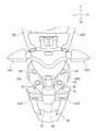
図4に示すように、自動二輪車1は、左リアフラッシャー64Lおよび右リアフラッシャー64Rを備えている。図3に示すように、左リアフラッシャー64Lおよび右リアフラッシャー64Rは、リアフェンダ62に設けられている。図2に示すように、左リアフラッシャー64Lおよび右リアフラッシャー64Rは、テールライト60より前方に配置されている。左リアフラッシャー64Lおよび右リアフラッシャー64Rは、テールライト60の中間点60Cより前方に配置されている。左リアフラッシャー64Lおよび右リアフラッシャー64Rは、テールライト60より下方に配置されている。図5に示すように、左リアフラッシャー64Lは、テールライト60より左方に配置されている。右リアフラッシャー64Rは、テールライト60より右方に配置されている。なお、図5において、説明の便宜上、シート10およびグラブバー18の図示を省略している。図3に示すように、左リアフラッシャー64Lの後端64LRおよび右リアフラッシャー64Rの後端64RRは、左シートフレーム40Lの後端40LRおよび右シートフレーム40Rの後端40RRより後方に位置する。
As shown in FIG. 4, the motorcycle 1 includes a left
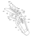
図1に示すように、自動二輪車1は、連結部材70と、マッドガード80と、板状部材90とを備えている。連結部材70は、樹脂材料よりも剛性の高い金属材料から形成されている。連結部材70は、テールライト60の下方に配置されている。図6に示すように、連結部材70は、左リアフラッシャー64Lより右方に配置されている。連結部材70は、右リアフラッシャー64Rより左方に配置されている。なお、図6において、説明の便宜上、シート10、グラブバー18およびテールライト60の図示を省略している。図2に示すように、連結部材70は、左リアフラッシャー64Lおよび右リアフラッシャー64Rより前方において、左シートフレーム40Lおよび右シートフレーム40Rに連結されている。連結部材70の前端70Fは、左リアフラッシャー64Lおよび右リアフラッシャー64Rより前方に位置する。本実施形態では、図7に示すように、連結部材70は、左シートフレーム40Lおよび右シートフレーム40Rに設けられたブラケット66に連結している。連結部材70とブラケット66とはボルト38によって相互に固定されている。連結部材70は、左シートフレーム40Lおよび右シートフレーム40Rに直接的に連結してもよい。連結部材70は、左シートフレーム40Lおよび右シートフレーム40Rから後方に延びる。連結部材70は、左シートフレーム40Lおよび右シートフレーム40Rから後斜め下方に延びる。
As shown in FIG. 1, the motorcycle 1 includes a connecting
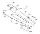
図8に示すように、連結部材70は、第1上壁71と、第1左側壁72Lと、第1右側壁72Rと、第1左壁73Lと、第1右壁73Rとを備えている。
As shown in FIG. 8, the connecting
図6に示すように、第1上壁71は、車両前後方向に延びる。第1上壁71は、車両平面視で、後輪7と重なる。第1上壁71は、後述のマッドガード80の第2左壁83Lと第2右壁83Rとの間に配置されている。図9に示すように、第1上壁71の下面71Bは、後述の板状部材90の第2上壁91の上面91Uに対向して配置されている。
As shown in FIG. 6, the first
図9に示すように、第1左側壁72Lは、第1上壁71の左端から左斜め下方に延びている。図10に示すように、第1左側壁72Lの左端75Lは、車両背面視で後輪7の左端7Lより左方に位置する。図8に示すように、第1左側壁72Lには、第1開口72LOが形成されている。第1開口72LOは、車両前後方向に延びる。第1左側壁72Lの前端部には、貫通孔72LPが形成されている。図6に示すように、第1左側壁72Lは、第1左部分74LAと、第2左部分LBとを備えている。第1左部分74LAには第1開口72LOが形成されている。第2左部分74LBは、第1左部分74LAより後方に位置する。第2左部分74LBには、第1開口72LOは形成されていない。第2左部分74LBの車幅方向の寸法L2は、第1左部分74LAの車幅方向の寸法L1より小さい。図2に示すように、第1左部分74LAの車両上下方向の寸法L3は、第2左部分74LBの車両上下方向の寸法L4より大きい。第1開口72LOの前縁72LFは、シート10の後端10Rより前方に位置する。第1開口72LOの後縁72LRは、テールライト60の中間点60Cより後方に位置する。第1開口72LOの後縁72LRは、車体カバー28の後端28RRより前方に位置する。
As shown in FIG. 9, the first left side wall 72 </ b> L extends diagonally downward to the left from the left end of the first
図9に示すように、第1右側壁72Rは、第1上壁71の右端から右斜め下方に延びている。図10に示すように、第1右側壁72Rの右端75Rは、車両背面視で後輪7の右端7Rより左方に位置する。図8に示すように、第1右側壁72Rには、第2開口72RO(図6も参照)が形成されている。第2開口72ROは、車両前後方向に延びる。第1右側壁72Rの前端部には、貫通孔72RPが形成されている。図6に示すように、第1右側壁72Rは、第1右部分74RAと、第2右部分RBとを備えている。第1右部分74RAには第2開口72ROが形成されている。第2右部分74RBは、第1右部分74RAより後方に位置する。第2右部分74RBには、第2開口72ROは形成されていない。第2右部分74RBの車幅方向の寸法R2は、第1右部分74RAの車幅方向の寸法R1より小さい。図2に示すように、第1右部分74RAの車両上下方向の寸法R3は、第2右部分74RBの車両上下方向の寸法R4より大きい。第2開口72ROの前縁72RFは、シート10の後端10Rより前方に位置する。第2開口72ROの後縁72RRは、テールライト60の中間点60Cより後方に位置する。第2開口72ROの後縁72RRは、車体カバー28の後端28RRより前方に位置する。
As shown in FIG. 9, the first right side wall 72 </ b> R extends obliquely downward to the right from the right end of the first
図8に示すように、第1左壁73Lは、第1左側壁72Lから左方に延びる。第1左壁73Lは、第1左係合部73LXを有している。第1左係合部73LXは、貫通孔である。第1左壁73Lの上面73LUは、後述のマッドガード80の第2左壁83Lの下面83LB(図11参照)に対向して配置されている。第1右壁73Rは、第1右側壁72Rから右方に延びる。第1右壁73Rは、第1右係合部73RXを有している。第1右係合部73RXは、貫通孔である。第1右壁73Rの上面73RUは、後述のマッドガード80の第2右壁83Rの下面83RB(図11参照)に対向して配置されている。
As shown in FIG. 8, the first
図11に示すように、板状部材90とマッドガード80とは一体に成形されている。マッドガード80と板状部材90とは別体に成形された別部材であってもよい。板状部材90は、連結部材70を形成する金属材料よりも軽い樹脂材料から成形されている。図2に示すように、板状部材90は、連結部材70の下方に配置されている。板状部材90は、連結部材70の第1開口72LOおよび第2開口72ROを覆う。板状部材90は、第1開口72LOおよび第2開口72ROを下方から覆う。なお、板状部材90は、連結部材70の上方に配置されてもよい。この場合、板状部材90は、第1開口72LOおよび第2開口72ROを上方から覆う。
As shown in FIG. 11, the plate-
図11に示すように、板状部材90は、第2上壁91と、第2左側壁92Lと、第2右側壁92R(図6も参照)と、第2下壁94とを備えている。
As shown in FIG. 11, the plate-
第2上壁91は、車両前後方向に延びる。第2上壁91は、連結部材70の第1上壁71(図8参照)に対向する位置に配置される。第2上壁91は、第1上壁71の下方に配置されている。第2上壁91は、後述のマッドガード80の第2左壁83Lと第2右壁83Rとの間に配置されている。第2上壁91は、開口91Oを備えている。
The second
図9に示すように、第2左側壁92Lは、第2上壁91の左端から左斜め下方に延びている。図6に示すように、第2左側壁92Lは、第1左側壁72Lに対向する位置に配置されている。第2左側壁92Lは、第1左側壁72Lの下方に配置されている。第2左側壁92Lは、車両平面視で第1左側壁72Lに形成された第1開口72LOと重なる。第2左側壁92Lは、第1開口72LOを覆う。図11に示すように、第2左側壁92Lの前端部には、第1左側壁72Lに形成された貫通孔72LP(図8参照)と係合する突起92LPが形成されている。図9に示すように、第2右側壁92Rは、第2上壁91の右端から右斜め下方に延びている。図6に示すように、第2右側壁92Rは、第1右側壁72Rに対向する位置に配置されている。第2右側壁92Rは、第1右側壁72Rの下方に配置されている。第2右側壁92Rは、車両平面視で第2右側壁72Rに形成された第2開口72ROと重なる。第2右側壁92Rは、第2開口72ROを覆う。図11に示すように、第2右側壁92Rの前端部には、第1右側壁72Rに形成された貫通孔72RP(図8参照)と係合する突起92RPが形成されている。なお、本実施形態では、第2左側壁92Lと第2右側壁92Rとは一体に成形された一つの部材であるが、第2左側壁92Lと第2右側壁92Rとは、別体に成形した別部材としてもよい。この場合、第2左側壁92Lが第1開口72LOを覆い、第2右側壁92Rが第2開口72ROを覆う。
As shown in FIG. 9, the second left side wall 92 </ b> L extends obliquely downward to the left from the left end of the second
図9に示すように、第2下壁94は、第2上壁91の下方に配置されている。第2下壁94は、車両前後方向に延びる。
As shown in FIG. 9, the second
図1に示すように、マッドガード80は、連結部材70に連結されている。マッドガード80は、連結部材70から後斜め下方に延びている。マッドガード80の後端80Rは、後輪7より後方に配置されている。
As shown in FIG. 1, the
図11に示すように、マッドガード80は、本体部81と、第2左壁83Lと、第2右壁83Rとを備えている。本体部81と、第2左壁83Lと、第2右壁83Rとは一体に成形されている。第2左壁83Lは、車両前後方向に延びている。第2左壁83Lは、板状部材90の第2上壁91より左方に位置する。図4に示すように、第2左壁83Lは、車両平面視でグラブバー18と重なる。図6に示すように、第2左壁83Lは、第1左側壁72Lの第2左部分74LBの左方に配置されている。第2左壁83Lは、連結部材70の第1左壁73L(図8参照)の上方に位置する。図11に示すように、第2左壁83Lは、第1左係合部73LX(図8参照)と係合する第2左係合部83LXを備えている。図6に示すように、第1左係合部73LXと第2左係合部83LXとにボルト48が挿入されることによって、第1左係合部73LXと第2左係合部83LXとが係合する。
As shown in FIG. 11, the
図11に示すように、第2右壁83Rは、車両前後方向に延びている。第2右壁83Rは、板状部材90の第2上壁91より右方に位置する。図4に示すように、第2右壁83Rは、車両平面視でグラブバー18と重なる。図6に示すように、第2右壁83Rは、第1右側壁72Rの第2右部分74RBの右方に配置されている。第2右壁83Rは、連結部材70の第1右壁73R(図8参照)の上方に位置する。図11に示すように、第2右壁83Rは、第1右係合部73RX(図8参照)と係合する第2右係合部83RXを備えている。図6に示すように、第1右係合部73RXと第2右係合部83RXとにボルト48が挿入されることによって、第1右係合部73RXと第2右係合部83RXとが係合する。
As shown in FIG. 11, the second
図11に示すように、本体部81は、板状部材90から後斜め下方に延びている。本体部81には、ライセンスプレート(図示せず)を取り付け可能な第1取付部82Aが形成されている。ライセンスプレートは、マッドガード80に配置される。本体部81には、プレート用ライト(図2参照)86を取り付け可能な第2取付部82Bが形成されている。第2取付部82Bは、第1取付部82Aより上方に位置する。図2に示すように、第2取付部82Bには、プレート用ライト86が取り付けられている。プレート用ライト86は、ライセンスプレートが第1取付部82Aに取り付けられたとき、ライセンスプレートに光を照射する。プレート用ライト86とバッテリ12とは、ケーブル14(図9参照)によって接続されている。図9に示すように、ケーブル14は、板状部材90の第2下壁94の上に配置されている。ケーブル14は、第2上壁91の開口91Oの下方に配置されている。ケーブル14は、連結部材70の第1上壁71の下方に配置されている。
As shown in FIG. 11, the
以上のように、自動二輪車1によれば、図6に示すように、連結部材70は、左リアフラッシャー64Lおよび右リアフラッシャー64Rより前方において左シートフレーム40Lおよび右シートフレーム40Rに連結している。このため、連結部材70と左右シートフレーム40L、40Rとの連結位置から、マッドガード80の後端80Rの位置までが比較的長くなる。しかし、剛性の高い連結部材70が左右のシートフレーム40L、40Rとマッドガード80とを連結しているため、リアフェンダ62とマッドガード80とを一体に成形した場合と比較して、マッドガード80の車両前後方向の長さは短くなり、剛性は高くなる。また、図9に示すように、連結部材70の第1左側壁72Lおよび第1右側壁72Rはそれぞれ斜め下方に延びている。このため、第1左側壁72Lおよび第1右側壁72Rが単に下方に延びる場合、すなわち連結部材70の断面形状がU字状の場合と比較して、連結部材70が同じ重量であっても連結部材70の車幅方向の長さが長くなる。この結果、連結部材70における泥除け性能が向上する。また、連結部材70には、自動二輪車1の軽量化のために第1開口72LOおよび第2開口72ROが形成されているが、第1開口72LOおよび第2開口72ROは、軽量な樹脂材料製の板状部材90に覆われている。このため、連結部材70の第1左側壁72Lおよび第1右側壁72Rが斜め下方に延びている場合であっても、後輪7から巻き上げられた泥等が第1開口72LOおよび第2開口72ROを介してテールライト60や乗員に当たることを防止することができる。
As described above, according to the motorcycle 1, as shown in FIG. 6, the connecting
本実施形態の自動二輪車1によれば、図11に示すように、板状部材90とマッドガード80とは一体に成形されている。このため、板状部材90とマッドガード80とを接続する部品を削減することができると共に、部品の削減による軽量化が実現される。
According to the motorcycle 1 of the present embodiment, as shown in FIG. 11, the plate-
本実施形態の自動二輪車1によれば、図8および図11に示すように、連結部材70の第1上壁71および板状部材90の第2上壁91は、第2左壁83Lと第2右壁83Rとの間に配置され、連結部材70の第1上壁71の下面71B(図9参照)は、板状部材90の第2上壁91の上面91U(図9参照)に対向し、第1左壁73Lの上面73LUおよび第1右壁73Rの上面73RUは、それぞれ、第2左壁83Lの下面83LBおよび第2右壁83Rの下面83LBに対向する。これにより、連結部材70とマッドガード80とをより確実に連結することができる。
According to the motorcycle 1 of the present embodiment, as shown in FIGS. 8 and 11, the first
本実施形態の自動二輪車1によれば、図6に示すように、第1左側壁72Lの第2左部分74LBの左方には第2左壁83Lが配置されている。このため、第2左部分74LBの車幅方向の寸法L2を第1左部分74LAの車幅方向の寸法L1より小さくしても、後輪7から巻き上げられた泥等は第2左壁83Lにおいて防ぐことができる。また、第1右側壁72Rの第2右部分74RBの右方には第2右壁83Rが配置されている。このため、第2右部分74RBの車幅方向の寸法R2を第1右部分74RAの車幅方向の寸法R1より小さくしても、後輪7から巻き上げられた泥等は第2右壁83Rにおいて防ぐことができる。この結果、連結部材70を小型化することができ、軽量化が実現される。
According to the motorcycle 1 of the present embodiment, as shown in FIG. 6, the second
本実施形態の自動二輪車1によれば、図2に示すように、第1左部分74LAの車両上下方向の寸法L3は、第2左部分74LBの車両上下方向の寸法L4より大きく、第1右部分74RAの車両上下方向の寸法R3は、第2右部分74RBの車両上下方向の寸法R4より大きい。これにより、連結部材70の剛性を確保しつつ、連結部材70自体の軽量化を実現することができる。
According to the motorcycle 1 of the present embodiment, as shown in FIG. 2, the dimension L3 of the first left portion 74LA in the vehicle up-down direction is larger than the dimension L4 of the second left portion 74LB in the vehicle up-down direction. The dimension R3 in the vehicle vertical direction of the portion 74RA is larger than the dimension R4 in the vehicle vertical direction of the second right portion 74RB. Thereby, weight reduction of connecting
本実施形態の自動二輪車1によれば、図9に示すように、ケーブル14の下方には第2下壁94が配置されているため、後輪7から巻き上がる泥や石等がケーブル14に当たることを防止することができる。
According to the motorcycle 1 of the present embodiment, as shown in FIG. 9, since the second
本実施形態の自動二輪車1によれば、図10に示すように、車両背面視で、第1左側壁72Lの左端75Lは、後輪7の左端7Lより左方に位置し、第1右側壁72Rの右端75Rは、後輪7の右端7Rより右方に位置する。このように、連結部材70が車幅方向に大きく広がっているため、連結部材70における泥除け性能が向上する。
According to the motorcycle 1 of the present embodiment, as shown in FIG. 10, the
本実施形態の自動二輪車1によれば、図2に示すように、第1開口72LOの前縁72LFおよび第2開口72ROの前縁72RFは、シート10の後端10Rより前方に位置し、第1開口72LOの後縁72LRおよび第2開口72ROの後縁72RRは、テールライト60の前後方向の中間点60Cより後方に位置する。このように、第1開口72LOおよび第2開口72ROが大きく形成されているため、連結部材70の軽量化が実現される。
According to the motorcycle 1 of the present embodiment, as shown in FIG. 2, the front edge 72LF of the first opening 72LO and the front edge 72RF of the second opening 72RO are located in front of the
ここに用いられた用語及び表現は、説明のために用いられたものであって限定的に解釈するために用いられたものではない。ここに示されかつ述べられた特徴事項の如何なる均等物をも排除するものではなく、本発明のクレームされた範囲内における各種変形をも許容するものであると認識されなければならない。本発明は、多くの異なった形態で具現化され得るものである。この開示は本発明の原理の実施形態を提供するものと見なされるべきである。それらの実施形態は、本発明をここに記載しかつ/又は図示した好ましい実施形態に限定することを意図するものではないという了解のもとで、実施形態がここに記載されている。ここに記載した実施形態に限定されるものではない。本発明は、この開示に基づいて当業者によって認識され得る、均等な要素、修正、削除、組み合わせ、改良及び/又は変更を含むあらゆる実施形態をも包含する。クレームの限定事項はそのクレームで用いられた用語に基づいて広く解釈されるべきであり、本明細書あるいは本願のプロセキューション中に記載された実施形態に限定されるべきではない。 The terms and expressions used herein are used for explanation and are not used for limited interpretation. It should be recognized that any equivalents of the features shown and described herein are not excluded and that various modifications within the claimed scope of the invention are permitted. The present invention can be embodied in many different forms. This disclosure should be regarded as providing embodiments of the principles of the invention. The embodiments are described herein with the understanding that the embodiments are not intended to limit the invention to the preferred embodiments described and / or illustrated herein. It is not limited to the embodiment described here. The present invention also encompasses any embodiment that includes equivalent elements, modifications, deletions, combinations, improvements and / or changes that may be recognized by those skilled in the art based on this disclosure. Claim limitations should be construed broadly based on the terms used in the claims and should not be limited to the embodiments described herein or in the process of this application.
60 テールライト
62 リアフェンダ
64L 左リアフラッシャー
64R 右リアフラッシャー
70 連結部材
72L 第1左側壁
72LO 第1開口
72R 第1右側壁
72RO 第2開口
80 マッドガード
90 板状部材
60
Claims (8)
前記メインフレームから後方に延びる左シートフレームと、
前記メインフレームから後方に延び、前記左シートフレームの右方に配置された右シートフレームと、
前記左シートフレームおよび前記右シートフレームより後方に配置されたテールライトと、
前記テールライトより前方に配置された左リアフラッシャーおよび右リアフラッシャーと、
前記左シートフレームおよび前記右シートフレームの下方に配置された後輪と、
前記左シートフレームおよび前記右シートフレームの下方かつ前記後輪の一部の上方に配置されたリアフェンダと、
前記テールライトの下方に配置され、前記左リアフラッシャーおよび前記右リアフラッシャーより前方において前記左シートフレームおよび前記右シートフレームに連結され、前記左シートフレームおよび前記右シートフレームから後方に延びる金属製の連結部材と、
前記連結部材に連結され、前記連結部材から後斜め下方に延び、その後端が前記後輪より後方に配置されたマッドガードと、を備え、
前記連結部材は、車両平面視で、前記後輪と重なる第1上壁と、前記第1上壁の左端から左斜め下方に延び、第1開口が形成された第1左側壁と、前記第1上壁の右端から右斜め下方に延び、第2開口が形成された第1右側壁と、を備え、
前記第1開口および前記第2開口は、前記連結部材より軽い樹脂材料から成形された板状部材によってそれぞれ覆われている、鞍乗型車両。 The mainframe,
A left seat frame extending rearward from the main frame;
A right seat frame extending rearward from the main frame and disposed to the right of the left seat frame;
A taillight disposed behind the left seat frame and the right seat frame;
A left rear flasher and a right rear flasher disposed in front of the taillight;
A rear wheel disposed below the left seat frame and the right seat frame;
A rear fender disposed below the left seat frame and the right seat frame and above a part of the rear wheel;
The metal is disposed below the taillight, is connected to the left seat frame and the right seat frame in front of the left rear flasher and the right rear flasher, and extends rearward from the left seat frame and the right seat frame. A connecting member;
A mudguard connected to the connecting member, extending obliquely downward and rearward from the connecting member, and having a rear end disposed rearward of the rear wheel;
The connecting member includes a first upper wall that overlaps with the rear wheel in a plan view of the vehicle, a first left side wall that extends diagonally to the left from the left end of the first upper wall and has a first opening, and the first A first right side wall that extends diagonally downward to the right from the right end of one upper wall and has a second opening formed thereon,
The straddle-type vehicle, wherein the first opening and the second opening are each covered by a plate-like member molded from a resin material lighter than the connecting member.
前記マッドガードは、前記第1左係合部と係合する第2左係合部を有する第2左壁と、前記第1右係合部と係合する第2右係合部を有する第2右壁と、を備え、
前記板状部材は、前記第1上壁に対向する位置に配置される第2上壁と、前記第2上壁の左端から左斜め下方に延び、前記第1開口を覆う第2左側壁と、前記第2上壁の右端から右斜め下方に延び、前記第2開口を覆う第2右側壁と、を備え、
前記連結部材の前記第1上壁および前記板状部材の前記第2上壁は、前記第2左壁と前記第2右壁との間に配置され、
前記連結部材の第1上壁の下面は、前記板状部材の前記第2上壁の上面に対向し、
前記第1左壁の上面および前記第1右壁の上面は、それぞれ、前記第2左壁の下面および前記第2右壁の下面に対向する、請求項1または2項に記載の鞍乗型車両。 The connecting member has a first left engaging portion, has a first left wall extending leftward from the first left side wall, and a first right engaging portion, and extends rightward from the first right side wall. A first right wall extending,
The mud guard has a second left wall having a second left engagement portion that engages with the first left engagement portion, and a second right engagement portion that engages with the first right engagement portion. A right wall, and
The plate-like member includes a second upper wall disposed at a position facing the first upper wall, a second left wall extending obliquely downward to the left from the left end of the second upper wall and covering the first opening. A second right side wall extending obliquely downward to the right from the right end of the second upper wall and covering the second opening,
The first upper wall of the connecting member and the second upper wall of the plate-like member are disposed between the second left wall and the second right wall;
The lower surface of the first upper wall of the connecting member is opposed to the upper surface of the second upper wall of the plate member,
3. The saddle riding type according to claim 1, wherein an upper surface of the first left wall and an upper surface of the first right wall are opposed to a lower surface of the second left wall and a lower surface of the second right wall, respectively. vehicle.
前記第2左壁は、前記第1左側壁の前記第2左部分の左方に配置され、
前記第1右側壁は、前記第2開口が形成された第1右部分と、前記第1右部分より後方に位置し、車幅方向の寸法が前記第1右部分の車幅方向の寸法より小さい第2右部分と、を備え、
前記第2右壁は、前記第1右側壁の前記第2右部分の右方に配置されている、請求項3に記載の鞍乗型車両。 The first left side wall is positioned rearward of the first left portion where the first opening is formed and the first left portion, and the vehicle width direction dimension is greater than the vehicle width direction dimension of the first left portion. A small second left portion,
The second left wall is disposed to the left of the second left portion of the first left side wall;
The first right side wall is positioned rearward of the first right part in which the second opening is formed and the first right part, and the vehicle width direction dimension is larger than the vehicle width direction dimension of the first right part. A small second right part, and
The straddle-type vehicle according to claim 3, wherein the second right wall is disposed to the right of the second right portion of the first right side wall.
前記第1右部分の車両上下方向の寸法は、前記第2右部分の車両上下方向の寸法より大きい、請求項4に記載の鞍乗型車両。 The vehicle vertical dimension of the first left portion is larger than the vehicle vertical dimension of the second left portion,
The straddle-type vehicle according to claim 4, wherein a dimension of the first right portion in a vehicle vertical direction is larger than a dimension of the second right portion in a vehicle vertical direction.
前記マッドガードに配置され、ライセンスプレートを取り付け可能な取付部と、
前記取付部の上方に配置され、前記ライセンスプレートが前記取付部に取り付けられたとき、前記ライセンスプレートに光を照射するプレート用ライトと、
前記バッテリおよび前記プレート用ライトに接続されたケーブルと、を備え、
前記板状部材は、前記第2上壁の下方に配置され、車両前後方向に延びる第2下壁、を備え、
前記ケーブルは、前記第2下壁の上に配置されている、請求項3から5のいずれか一項に記載の鞍乗型車両。 A battery disposed in front of the taillight;
A mounting portion disposed on the mudguard and capable of mounting a license plate;
A plate light that is disposed above the mounting portion and irradiates light to the license plate when the license plate is mounted on the mounting portion;
A cable connected to the battery and the plate light,
The plate-like member includes a second lower wall that is disposed below the second upper wall and extends in the vehicle front-rear direction.
The straddle-type vehicle according to any one of claims 3 to 5, wherein the cable is disposed on the second lower wall.
前記第1開口および前記第2開口は、車両前後方向に延び、前記第1開口の前縁および前記第2開口の前縁は、前記シートの後端より前方に位置し、前記第1開口の後縁および前記第2開口の後縁は、前記テールライトの前後方向の中間点より後方に位置する、請求項1から7のいずれか一項に記載の鞍乗型車両。 A seat disposed above the left seat frame and the right seat frame;
The first opening and the second opening extend in the vehicle front-rear direction, and the front edge of the first opening and the front edge of the second opening are located forward of the rear end of the seat, The straddle-type vehicle according to any one of claims 1 to 7, wherein a rear edge and a rear edge of the second opening are located behind an intermediate point in the front-rear direction of the taillight.
Priority Applications (3)
| Application Number | Priority Date | Filing Date | Title |
|---|---|---|---|
| JP2014108811A JP2015223902A (en) | 2014-05-27 | 2014-05-27 | Saddle riding type vehicle |
| EP15152771.0A EP2949558B1 (en) | 2014-05-27 | 2015-01-28 | Straddle-type vehicle |
| ES15152771.0T ES2578163T3 (en) | 2014-05-27 | 2015-01-28 | Straddle Type Vehicle |
Applications Claiming Priority (1)
| Application Number | Priority Date | Filing Date | Title |
|---|---|---|---|
| JP2014108811A JP2015223902A (en) | 2014-05-27 | 2014-05-27 | Saddle riding type vehicle |
Publications (1)
| Publication Number | Publication Date |
|---|---|
| JP2015223902A true JP2015223902A (en) | 2015-12-14 |
Family
ID=52423612
Family Applications (1)
| Application Number | Title | Priority Date | Filing Date |
|---|---|---|---|
| JP2014108811A Pending JP2015223902A (en) | 2014-05-27 | 2014-05-27 | Saddle riding type vehicle |
Country Status (3)
| Country | Link |
|---|---|
| EP (1) | EP2949558B1 (en) |
| JP (1) | JP2015223902A (en) |
| ES (1) | ES2578163T3 (en) |
Cited By (1)
| Publication number | Priority date | Publication date | Assignee | Title |
|---|---|---|---|---|
| TWI639529B (en) * | 2016-10-04 | 2018-11-01 | 日商山葉發動機股份有限公司 | Straddled vehicle |
Families Citing this family (2)
| Publication number | Priority date | Publication date | Assignee | Title |
|---|---|---|---|---|
| CN107878621B (en) * | 2016-09-30 | 2020-02-21 | 雅马哈发动机株式会社 | Straddle-type vehicle |
| JP6841020B2 (en) * | 2016-11-30 | 2021-03-10 | スズキ株式会社 | Position luminaires and vehicles |
Family Cites Families (4)
| Publication number | Priority date | Publication date | Assignee | Title |
|---|---|---|---|---|
| JP2008162511A (en) | 2006-12-28 | 2008-07-17 | Yamaha Motor Co Ltd | Straddle type vehicle |
| JP5091804B2 (en) * | 2008-08-22 | 2012-12-05 | 本田技研工業株式会社 | Saddle bag mounting structure for motorcycles |
| JP5332666B2 (en) * | 2009-02-03 | 2013-11-06 | スズキ株式会社 | Motorcycle rear fender structure and motorcycle |
| JP5944228B2 (en) * | 2012-05-28 | 2016-07-05 | 本田技研工業株式会社 | Saddle riding |
-
2014
- 2014-05-27 JP JP2014108811A patent/JP2015223902A/en active Pending
-
2015
- 2015-01-28 EP EP15152771.0A patent/EP2949558B1/en active Active
- 2015-01-28 ES ES15152771.0T patent/ES2578163T3/en active Active
Cited By (1)
| Publication number | Priority date | Publication date | Assignee | Title |
|---|---|---|---|---|
| TWI639529B (en) * | 2016-10-04 | 2018-11-01 | 日商山葉發動機股份有限公司 | Straddled vehicle |
Also Published As
| Publication number | Publication date |
|---|---|
| EP2949558A1 (en) | 2015-12-02 |
| EP2949558B1 (en) | 2016-06-15 |
| ES2578163T3 (en) | 2016-07-21 |
Similar Documents
| Publication | Publication Date | Title |
|---|---|---|
| JP3157145U (en) | Motorcycle | |
| JP5980250B2 (en) | Saddle riding | |
| JP2012071779A (en) | Fairing structure for straddle-ride type vehicle | |
| JP2016013767A (en) | Saddle-riding type vehicle | |
| EP3141464B1 (en) | Rear fender for motorcycle | |
| JP4676281B2 (en) | Vehicle flap | |
| JP2014118099A (en) | Motor bicycle | |
| JP5460511B2 (en) | Rear fender for vehicles | |
| JP2012136161A (en) | Saddle riding vehicle | |
| JP2015223902A (en) | Saddle riding type vehicle | |
| JP2013173472A (en) | Saddle-riding type vehicle | |
| EP1361144B1 (en) | Headlight apparatus for motorcycles | |
| JP2016135655A (en) | Saddle riding type vehicle | |
| JP6534743B2 (en) | Front fork of straddle type vehicle | |
| JP2009154839A (en) | Motorcycle | |
| JP2013203083A (en) | Saddle-ride type vehicle | |
| JP2012240520A (en) | Straddle type vehicle | |
| JP6448157B2 (en) | Motorcycle headlight guard structure | |
| JP2010058763A (en) | Saddle-riding type vehicle | |
| JP6132628B2 (en) | Rear fender support structure for saddle-ride type vehicles | |
| JP2009029213A (en) | Mounting structure for windscreen | |
| JP6682410B2 (en) | Cooling water reservoir tank for saddle type vehicles | |
| JP2011148452A (en) | Rear structure of saddle riding type vehicle | |
| JP6254507B2 (en) | Saddle-type vehicle with rear grip | |
| JP6962661B2 (en) | Seat frame for saddle-mounted vehicles |