JP2015217841A - Warning lamp control system, vehicle including warning lamp control system, program of warning lamp control system - Google Patents
Warning lamp control system, vehicle including warning lamp control system, program of warning lamp control system Download PDFInfo
- Publication number
- JP2015217841A JP2015217841A JP2014103468A JP2014103468A JP2015217841A JP 2015217841 A JP2015217841 A JP 2015217841A JP 2014103468 A JP2014103468 A JP 2014103468A JP 2014103468 A JP2014103468 A JP 2014103468A JP 2015217841 A JP2015217841 A JP 2015217841A
- Authority
- JP
- Japan
- Prior art keywords
- warning light
- control system
- display
- unit
- pattern
- Prior art date
- Legal status (The legal status is an assumption and is not a legal conclusion. Google has not performed a legal analysis and makes no representation as to the accuracy of the status listed.)
- Granted
Links
Images
Landscapes
- Lighting Device Outwards From Vehicle And Optical Signal (AREA)
Abstract
【課題】警光灯の状態を容易に認識することができる警光灯制御システムおよび警光灯制御システムを含む車両、警光灯制御システムのプログラムを提供することである。
【解決手段】本発明に係る警光灯制御システム100は、CPU210が、ユーザによるサイレンアンプ200の操作に基づいた操作信号に応じ、RAM241、EEPROM242から選定された警光灯500の点灯パターンを用いて警光灯500を点灯制御する。また、CPU210は、データテーブルに基づいて消防車900の車内のサイレンアンプ200の複数のLED231の表示パターンを制御する。
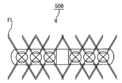
【選択図】図4
A warning light control system capable of easily recognizing the state of a warning light, a vehicle including the warning light control system, and a program for the warning light control system.
In a warning light control system 100 according to the present invention, a CPU 210 uses a lighting pattern of a warning light 500 selected from a RAM 241 and an EEPROM 242 in response to an operation signal based on an operation of a siren amplifier 200 by a user. The lighting of the warning light 500 is controlled. Moreover, CPU210 controls the display pattern of several LED231 of the siren amplifier 200 in the vehicle of the fire engine 900 based on a data table.
[Selection] Figure 4
Description
本発明は、主に警光灯制御システムおよび警光灯制御システムを含む車両、警光灯制御システムのプログラムに関する。 The present invention mainly relates to a warning light control system, a vehicle including the warning light control system, and a program for the warning light control system.
従来から、パトロールカーのような緊急用車両等においては、基台上に複数個の回転灯を配置するとともに、この回転灯を赤色などの着色透光材料で構成したグローブで覆い、回転灯から発生してグローブで着色された警告光を周囲に散光するようにした警光灯制御システムが用いられている。この警光灯制御システムについては、種々の開発が行なわれている。 Conventionally, in emergency vehicles such as patrol cars, a plurality of revolving lights are arranged on a base, and the revolving lights are covered with a glove made of a colored light-transmitting material such as red. A warning light control system is used in which warning light generated and colored with a glove is scattered around. Various developments have been made on this warning light control system.
例えば、特許文献1(特開2006−123813号公報)には、従来の警光灯システムの持っている点滅変化パターンが単調であり十分な注意を喚起できないという課題を解決する警光灯システムについて開示されている。 For example, Patent Document 1 (Japanese Patent Laid-Open No. 2006-12381) discloses a warning light system that solves the problem that a blinking change pattern of a conventional warning light system is monotonous and cannot attract sufficient attention. It is disclosed.
特許文献1記載の警光灯システムにおいては、スピーカ及び複数個の発光ユニットが基台に配置されてなる警光灯と、警光灯の各発光ユニットを独立して点灯制御することのできる制御装置とを備え、制御装置は、警光灯に対して、所定周期で発光ユニットを点滅させる点滅信号を送り出すとともに、スピーカに対して周波数が周期的に変化するサイレン信号を送り出すものであり、発光ユニットを点滅させる周期は、サイレン信号の周波数の変化周期と同期がとられているものである。
In the warning light system described in
また、特許文献2(特開2013−56086号公報)には、車両から離れた作業者または複数台の緊急車両を統括する現場監督者などが、車両の状態を把握し易い、ライト制御システムおよび車両について開示されている。 Patent Document 2 (Japanese Patent Application Laid-Open No. 2013-56086) discloses a light control system that allows an operator away from a vehicle or a site supervisor who supervises a plurality of emergency vehicles to easily grasp the state of the vehicle. A vehicle is disclosed.
特許文献2記載のライト制御システムにおいては、車両に搭載することが可能なライト制御システムであって、車両の外面に設置される少なくとも1つのライトと、車両の状態を測定するためのセンサと、センサからの車両の状態に応じて、少なくとも1つのライトの点灯方法を変更するためのプロセッサとを備えたものである。
The light control system described in
以上のように、特許文献1または特許文献2に記載された装置は、記載された効果を奏する。
As described above, the device described in
しかしながら、警光灯システムを制御する警光灯制御システムにおいては、次の課題も残されている。例えば、警光灯制御システムにおいて警光灯の点灯状態を、運転手などの乗員が認識することは、困難である。 However, the following problems remain in the warning light control system for controlling the warning light system. For example, it is difficult for an occupant such as a driver to recognize the lighting state of a warning light in a warning light control system.
本発明の目的は、警光灯の点灯状態を容易に車内から認識することができる警光灯制御システムおよび警光灯制御システムを含む車両、警光灯制御システムのプログラムを提供することである。 An object of the present invention is to provide a warning light control system and a vehicle including the warning light control system that can easily recognize the lighting state of the warning light from the inside of the vehicle, and a program for the warning light control system. .
(1)
一局面に従う警光灯制御システムは、複数の発光部が配設された警光灯を制御する、警光灯制御システムであって、ユーザの操作に基づいて、複数の操作信号を出力する操作部と、車内において複数の表示を行うことが可能な表示部と、警光灯の点灯パターンおよび表示部の表示パターンを、操作部の操作信号にそれぞれ対応付けたデータテーブルを記憶する記憶部と、制御部と、を含み、制御部は、操作部からの操作信号とデータテーブルとによって対応付けられた警光灯の点灯パターンを用いて警光灯を制御するとともに、当該操作信号とデータテーブルとによって対応付けられた表示部の表示パターンを用いて表示部を制御するものである。
(1)
A warning light control system according to an aspect is a warning light control system that controls a warning light provided with a plurality of light emitting units, and that outputs a plurality of operation signals based on a user operation. A storage unit that stores a data table that associates the lighting pattern of the warning light and the display pattern of the display unit with the operation signal of the operation unit, respectively, The control unit, and the control unit controls the warning light using the lighting pattern of the warning light associated with the operation signal from the operation unit and the data table, and the operation signal and the data table. The display unit is controlled using the display pattern of the display unit associated with each other.
本発明にかかる警光灯制御システムは、制御部が、ユーザによる操作部の操作に基づいた操作信号に応じ、記憶部から選定された警光灯の点灯パターンを用いて警光灯を点灯制御する。また、制御部は、データテーブルに基づいて車内の表示部の表示パターンを制御する。 In the warning light control system according to the present invention, the control unit controls the lighting of the warning light using the lighting pattern of the warning light selected from the storage unit according to the operation signal based on the operation of the operation unit by the user. To do. Moreover, a control part controls the display pattern of the display part in a vehicle based on a data table.
この場合、制御部は、警光灯を制御するとともに、データテーブルに基づいて、警光灯の点灯制御を示す表示パターンを車内の表示部に示すことができる。
したがって、車内の表示部を確認することで、警光灯の点灯制御の内容を認識することができる。例えば、ユーザは、車内に居ながら、実際の警光灯の点灯状態を認識することができる。
In this case, the control unit can control the warning light and display a display pattern indicating the lighting control of the warning light on the display unit in the vehicle based on the data table.
Therefore, the content of the lighting control of the warning light can be recognized by checking the display unit in the vehicle. For example, the user can recognize the actual lighting state of the warning light while in the vehicle.
(2)
第2の発明にかかる警光灯制御システムは、一局面の発明にかかる警光灯制御システムにおいて、表示部は、操作部と一体に形成されてもよい。
(2)
The warning light control system according to a second aspect of the present invention is the warning light control system according to one aspect of the invention, wherein the display unit may be formed integrally with the operation unit.
この場合、表示部は、操作部と一体に形成されているので、ユーザは、操作を行うとともに、容易に実際の警光灯の点灯状態を認識することができる。 In this case, since the display unit is formed integrally with the operation unit, the user can perform the operation and easily recognize the actual lighting state of the warning light.
(3)
第3の発明にかかる警光灯制御システムは、一局面または第2の発明にかかる警光灯制御システムにおいて、表示部は、操作部の一機能表示と兼用されてもよい。
(3)
In the warning light control system according to the third aspect of the present invention, in the warning light control system according to one aspect or the second aspect of the invention, the display unit may be used as one function display of the operation unit.
この場合、表示部を新たに別途設ける場合と異なり、兼用させることができるので、省スペース化を図ることができる。 In this case, unlike the case where a display portion is newly provided separately, the display portion can be used together, so that space can be saved.
(4)
第4の発明にかかる警光灯制御システムは、一局面または第2、第3の発明にかかる警光灯制御システムにおいて、データテーブルは、警光灯の点灯パターンと類似する点灯パターンを表示部の表示パターンとして記録されてもよい。
なお、類似とは、警光灯の点灯部分と、表示部の点灯部分との数が異なる場合でも、警光灯と表示部との点灯パターンが同じことを意味する。例えば、警光灯の一方向から点灯状態、消灯状態を繰り返す場合に、表示部の一方向から点灯状態、消灯状態を繰り返す。
(4)
A warning light control system according to a fourth aspect is the warning light control system according to one aspect or the second and third aspects, wherein the data table displays a lighting pattern similar to the lighting pattern of the warning light. May be recorded as a display pattern.
Note that “similar” means that the lighting pattern of the warning light and the display unit is the same even when the number of the lighting parts of the warning light and the number of the lighting parts of the display unit are different. For example, when the lighting state and the extinguishing state are repeated from one direction of the warning light, the lighting state and the extinguishing state are repeated from one direction of the display unit.
この場合、警光灯の点灯パターンと類似する点灯パターンを表示部の表示パターンとして記録するため、ユーザは、実際の警光灯の点灯状態を容易に認識することができる。 In this case, since the lighting pattern similar to the lighting pattern of the warning light is recorded as the display pattern of the display unit, the user can easily recognize the actual lighting state of the warning light.
(5)
第5の発明にかかる警光灯制御システムは、一局面または第2から第4の発明にかかる警光灯制御システムにおいて、方向指示器の出力を検知する検知部をさらに含み、制御部は、検知部の検知結果に応じて、警光灯の点灯パターンを方向指示器用の点灯パターンに変化させるとともに、警光灯の点灯パターンに応じて、表示部の表示パターンを方向指示器用の表示パターンに変化させてもよい。
(5)
A warning light control system according to a fifth aspect of the present invention is the warning light control system according to one aspect or the second to fourth aspects of the present invention, further including a detection unit that detects the output of the direction indicator, The lighting pattern of the warning light is changed to the lighting pattern for the direction indicator according to the detection result of the detection unit, and the display pattern of the display unit is changed to the display pattern for the direction indicator according to the lighting pattern of the warning light. It may be changed.
この場合、方向指示器の出力を検知する検知部をさらに含む。そして、制御部は、方向指示器の出力がある場合に、警光灯の点灯パターンを方向指示器用の点灯パターンに変化させることができる。例えば、警光灯が複数の点灯部を有する場合、左折するときに右から左へ連続して点滅させたり、右折するときに左から右へ連続して点滅させたりしてもよい。
さらに、検知部の検知結果に応じて、表示部の表示パターンを方向指示器用の表示パターン、すなわち、警光灯と類似するパターンに変化させてもよい。例えば、警光灯が複数の点灯部を有する場合、表示部の表示を左折するときに右から左へ連続して点滅させたり、右折するときに左から右へ連続して点滅させたりしてもよい。
In this case, it further includes a detector that detects the output of the direction indicator. And a control part can change the lighting pattern of a warning light into the lighting pattern for direction indicators, when there exists an output of a direction indicator. For example, when the warning light has a plurality of lighting sections, the warning light may be continuously flashed from right to left when making a left turn, or may be continuously flashed from left to right when making a right turn.
Furthermore, according to the detection result of the detection unit, the display pattern of the display unit may be changed to a display pattern for a direction indicator, that is, a pattern similar to a warning light. For example, if the warning light has multiple lighting parts, the display display blinks continuously from right to left when turning left, or blinks continuously from left to right when turning right Also good.
(6)
第6の発明にかかる警光灯制御システムは、一局面から第5の発明にかかる警光灯制御システムにおいて、データテーブルは、表示部の明暗データ、表示部の点滅消灯データまたは表示部の点灯消灯データを含んでもよい。
(6)
A warning light control system according to a sixth aspect of the present invention is the warning light control system according to the fifth aspect of the present invention from the one aspect, wherein the data table includes light / dark data of the display unit, blinking / unlit data of the display unit, or lighting of the display unit It may include extinguishing data.
この場合、データテーブルは、表示部の明暗データ、表示部の点滅消灯データまたは表示部の点灯消灯データを含むので、ユーザは、容易に表示部の表示を認識することができる。
ここで、表示部の明暗データは、表示部の一部の輝度を上昇または下降させるデータであり、表示部の点滅消灯データは、表示部の一部を複数回オンまたは複数回オフさせるデータであり、表示部の点灯消灯データは、表示部の一部をオンオフさせるデータである。
In this case, since the data table includes the light / dark data of the display unit, the blinking / unlit data of the display unit, or the on / off data of the display unit, the user can easily recognize the display on the display unit.
Here, the light / dark data of the display unit is data that increases or decreases the luminance of a part of the display unit, and the blinking / light-off data of the display unit is data that turns on or off a part of the display unit a plurality of times. Yes, the lighting / extinction data of the display unit is data for turning on / off a part of the display unit.
(7)
第7の発明にかかる警光灯制御システムは、第5の発明にかかる警光灯制御システムにおいて、表示部は、複数の発光素子を有し、表示部の発光素子および警光灯の発光部は、車両に取りつけられた状態において、少なくともそれぞれ左右方向に沿って配列する部分を有し、制御部は、検知部の検知結果に基づき、方向指示器が指示する向きが左であると判定したことを条件として、複数の発光素子の右側から左側へ順次点灯または明度を増加する表示パターンによって表示部を制御するとともに、複数の発光部が右側から左側へ順次点灯または明度を増加する発光パターンによって警光灯を制御する左側制御と、方向指示器が指示する向きが右であると判定したことを条件として、複数の発光素子が左側から右側へ順次点灯または明度を増加する表示パターンによって表示部を制御するとともに、複数の発光部が左側から右側へ順次点灯または明度を増加する発光パターンによって警光灯を制御する右側制御とを含んでもよい。
(7)
A warning light control system according to a seventh aspect is the warning light control system according to the fifth aspect, wherein the display unit has a plurality of light emitting elements, and the light emitting element of the display unit and the light emitting unit of the warning light Has at least a portion arranged in the left-right direction in a state where it is attached to the vehicle, and the control unit determines that the direction indicated by the direction indicator is the left based on the detection result of the detection unit. The display unit is controlled by a display pattern that sequentially lights or increases brightness from the right side to the left side of the plurality of light emitting elements, and a plurality of light emitting units are controlled by a light emission pattern that sequentially lights or increases brightness from the right side to the left side. Multiple light-emitting elements are sequentially turned on or increased in brightness from the left to the right on the condition that the left side control for controlling the warning light and the direction indicated by the direction indicator are determined to be right. Controls the display unit by the display pattern may include a right control for controlling the 警光 lamp by the light emission pattern in which a plurality of light-emitting portions is increased sequentially lighting or brightness from left to right.
この場合、制御部は、左側制御および右側制御を含むので、車両が右左折する際に、警光灯の点灯状態を、車内において容易に確認することができる。 In this case, since the control unit includes left side control and right side control, when the vehicle turns right or left, the lighting state of the warning light can be easily confirmed in the vehicle.
(8)
第8の発明にかかる警光灯制御システムは、一局面から第7の発明にかかる警光灯制御システムにおいて、警光灯は、散光式警光灯であってもよい。
(8)
A warning light control system according to an eighth aspect of the present invention is the warning light control system according to the seventh aspect of the present invention from one aspect, wherein the warning light may be a diffused warning light.
この場合、ユーザは、散光式警光灯の点灯制御を容易に認識することができる。 In this case, the user can easily recognize the lighting control of the diffused warning light.
(9)
他の局面にかかる警光灯制御システムを含む車両は、請求項1乃至8のいずれか1項に記載の警光灯制御システムと、複数の発光部が配設された警光灯と、を有するものである。
(9)
A vehicle including a warning light control system according to another aspect includes the warning light control system according to any one of
この場合、制御部は、警光灯を点灯制御するとともに、データテーブルに基づいて、警光灯の点灯制御を示す表示パターンを車内の表示部に示すことができる。
したがって、車内の表示部を確認することで、警光灯の点灯制御の内容を認識することができる。例えば、ユーザは、車内に居ながら、実際の警光灯の点灯状態を認識することができる。
また、表示部は、液晶、プラズマディスプレイ、発光ダイオード、7セグメント、エレクトロルミネッセンスの少なくともいずれかを含んでもよい。
In this case, the control unit can control the lighting of the warning light, and can display a display pattern indicating the lighting control of the warning light on the display unit in the vehicle based on the data table.
Therefore, the content of the lighting control of the warning light can be recognized by checking the display unit in the vehicle. For example, the user can recognize the actual lighting state of the warning light while in the vehicle.
The display unit may include at least one of a liquid crystal, a plasma display, a light emitting diode, 7 segments, and electroluminescence.
(10)
さらに他の局面に従う警光灯制御システムのプログラムは、複数の発光部が配設された警光灯を制御する、警光灯制御システムのプログラムであって、ユーザの操作に基づいて、複数の操作信号を出力する操作ステップと、車内において複数の表示を行うことが可能な表示ステップと、警光灯の点灯パターンおよび表示ステップの表示パターンを、操作ステップの操作信号にそれぞれ対応付けたデータテーブルを記憶する記憶ステップと、制御ステップと、を含み、制御ステップは、操作ステップからの操作信号とデータテーブルとによって対応付けられた警光灯の点灯パターンを用いて警光灯を制御するとともに、当該操作信号とデータテーブルとによって対応付けられた表示ステップの表示パターンを用いて表示ステップを制御するものである。
(10)
Still further, a warning light control system program according to another aspect is a warning light control system program for controlling a warning light provided with a plurality of light emitting units. A data table in which an operation step for outputting an operation signal, a display step capable of performing a plurality of displays in the vehicle, a lighting pattern of a warning light, and a display pattern of a display step are respectively associated with the operation signal of the operation step. A control step, and the control step controls the warning light using the lighting pattern of the warning light associated with the operation signal from the operation step and the data table, Control the display step using the display pattern of the display step associated with the operation signal and the data table A.
本発明にかかる警光灯制御システムのプログラムは、制御ステップが、ユーザによる操作ステップの操作に基づいた操作信号に応じ、記憶ステップから選定された警光灯の点灯パターンを用いて警光灯を点灯制御する。また、制御ステップは、データテーブルに基づいて車内の表示ステップの表示パターンを制御する。 According to the program of the warning light control system of the present invention, the control step uses the warning light lighting pattern selected from the storage step according to the operation signal based on the operation of the operation step by the user. Control lighting. The control step controls the display pattern of the in-vehicle display step based on the data table.
この場合、制御ステップは、警光灯を制御するとともに、データテーブルに基づいて、警光灯の点灯制御を示す表示パターンを車内の表示ステップに示すことができる。
したがって、車内の表示ステップを確認することで、警光灯の点灯制御の内容を認識することができる。例えば、ユーザは、車内に居ながら、実際の警光灯の点灯状態を認識することができる。
In this case, the control step can control the warning light and display a display pattern indicating the lighting control of the warning light on the display step in the vehicle based on the data table.
Therefore, it is possible to recognize the details of the lighting control of the warning light by confirming the display step in the vehicle. For example, the user can recognize the actual lighting state of the warning light while in the vehicle.
以下、本発明に係る実施の形態について図面を用いて説明する。以下の説明では、同一の部品には同一の符号を付してある。それらの名称および機能も同じである。したがって、それらについての詳細な説明は繰り返さない。 Embodiments according to the present invention will be described below with reference to the drawings. In the following description, the same parts are denoted by the same reference numerals. Their names and functions are also the same. Therefore, detailed description thereof will not be repeated.
本実施の形態においては、「車両」として、消防自動車(以下、単に消防車と呼ぶ。)に適用した場合について説明し、「警光灯」として散光式警光灯に適用した場合について説明する(以下、単に散光式警光灯を警光灯と呼ぶ。)。
ただし、「車両」は、パトロールカー、他の緊急車両、道路維持作業車、トラック、フォークリフト、建設機械などの他の車両であってもよい。
In the present embodiment, a case where the “vehicle” is applied to a fire engine (hereinafter simply referred to as a “fire engine”) will be described, and a case where the “vehicle” is applied to a diffused warning light will be described. (Hereafter, a diffused warning light is simply called a warning light.)
However, the “vehicle” may be another vehicle such as a patrol car, another emergency vehicle, a road maintenance work vehicle, a truck, a forklift, or a construction machine.
(実施の形態)
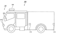
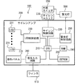
図1は、本発明に係る警光灯制御システム100を含む消防車900の概要を説明するための模式的側面図であり、図2は、本発明に係る警光灯制御システム100の主要部分の一例を示す模式図である。
(Embodiment)
FIG. 1 is a schematic side view for explaining an outline of a
まず、図1に示すように、消防車900の運転席に警光灯制御システム100のコントローラとなるサイレンアンプ200が設けられる。また、消防車900の屋根部分に、警光灯制御システム100に付随する警光灯500が設けられる。さらに、消防車900の前後左右に、警光灯制御システム100に付随するウィンカー610が配設される。
First, as shown in FIG. 1, a
図1および図2に示すように、警光灯制御システム100は、サイレンアンプ200および外部スイッチ550を含む。
外部スイッチ550は、警光灯500に接続される。
As shown in FIGS. 1 and 2, the warning
The
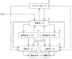
警光灯制御システム100におけるサイレンアンプ200は、CPU(中央演算処理装置)210、サイレン制御回路220、LED(発光ダイオード)制御回路230、複数のLED(発光ダイオード)231、RAM(ランダムアクセスメモリ)241、EEPROM(不揮発性メモリ)242、警光灯制御回路250、信号入力回路260、および操作パネル270を主に含む。
The
CPU210は、サイレン制御回路220、LED制御回路230、RAM241、EEPROM242、警光灯制御回路250、信号入力回路260と接続される。
警光灯制御回路250は、警光灯500と接続され、サイレン制御回路220は、サイレンユニット530と接続され、信号入力回路260は、ウィンカー610および操作パネル270と接続される。その結果、CPU210は、ウィンカー610の動作情報を認識することができる。
The warning
LED制御回路230は、複数のLED231と接続される。
また、CPU210は、外部スイッチ550からの入力、操作パネル270からの入力、およびウィンカー610の動作情報に基づいて、サイレン制御回路220、LED制御回路230、警光灯制御回路250等の制御を行う。
The
In addition, the
その結果、サイレン制御回路220によりサイレンユニット530を介してサイレンが吹鳴され、LED制御回路230により複数のLED231の点灯消灯および明暗点灯が制御され、警光灯制御回路250により警光灯500の点灯(回転点灯、2回点灯)が制御される。
なお、本実施の形態においては、2回点灯を例示するが、それに限定されず、3回、4回等、他の任意の回数点灯させてもよく、点灯時間を任意に変更してもよい。
As a result, the siren is blown through the
In the present embodiment, the lighting is exemplified twice, but the present invention is not limited to this. The lighting may be performed any other number of times such as three times, four times, etc., and the lighting time may be arbitrarily changed. .
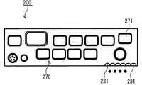
次に、図3は、サイレンアンプ200の一例を示す模式図である。図3に示すように、サイレンアンプ200は、操作パネル270、セグメント表示部271および複数のLED231を含む。
Next, FIG. 3 is a schematic diagram illustrating an example of the
本実施の形態にかかる複数のLED231は、サイレンアンプ200の状態を明示する機能を基本的に有し、例えば、マイク、補助、音声、CH(チャンネル)、電源、交差点スイッチ、渋滞スイッチ、警光灯スイッチ、サイレンスイッチ等の各種の状態を示すものである。
例えば、LED231のうち左端のLEDが点灯中の場合は、サイレンアンプ200がマイクの拡声音量を調整する状態にあることを意味し、その状態でサイレンアンプ200のジョグダイヤルを回せば、マイクの拡声音量を調整することができる状態にあることを意味する。
また、他のLED231は、例えば、外部機器から入力される補助入力の音量を調整する状態、外部に出力する音声チャネルを設定する状態等を意味する。つまり、点灯するLED231によって、サイレンアンプ200のジョグダイヤルによって設定される対象が変化する。
The plurality of
For example, when the leftmost LED of the
The
また、後述するLED231の表示は、後述する『パトロールモード』、『緊急モード』、『高警告モードA』、『高警告モードB』、『右折モード』、『左折モード』のいずれかで表示されている時にマイク音量を調整するため、ジョグダイヤルを操作すると、上述のモードが解除され、音量の機能の設定表示に変わる構造を採用している。なお、マイク・補助・音声・CH以外の操作スイッチについては、他のスイッチ部(図示省略)でオンオフを表示している。
The
また、図3の操作パネル270は、図面に符号を付していないが、音声再生スイッチ、モニタ、警光灯スイッチ、サイレン吹鳴スイッチ、テストスイッチ、SDカードスロット、吹鳴スイッチ、手動スイッチ、吹鳴音量スイッチ、ジョグダイヤル、電源スイッチ、マイク入力端子、音声入り切りスイッチ等を含む。
操作パネル270を操作することにより、各動作が制御され、各機能が稼動または停止される。
Further, although the
By operating the
(選定モード)
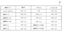
次に、図4は、警光灯制御システム100の選定モードの一例を示す模式図であり、図5は、警光灯制御システム100の選定モードの移行状態を示す模式図である。
(Selection mode)
Next, FIG. 4 is a schematic diagram illustrating an example of a selection mode of the warning
図4に示すように、警光灯制御システム100では、サイレンアンプ200および/または外部スイッチ550の操作により、『パトロールモード』、『緊急モード』、『高警告モードA』、『高警告モードB』、『右折モード』、『左折モード』の6種類から選定される。
なお、これらの各種モードを含むデータテーブル700は、図2に示したRAM(ランダムアクセスメモリ)241、EEPROM(不揮発性メモリ)242の少なくとも一方に記録される。EEPROM242として、一般的にフラッシュメモリが使用される。
また、6種類を例示して説明するが、これに限定されず、その他の数の任意の種類で設定されてもよい。
As shown in FIG. 4, in the warning
The data table 700 including these various modes is recorded in at least one of the RAM (random access memory) 241 and the EEPROM (nonvolatile memory) 242 shown in FIG. A flash memory is generally used as the
Moreover, although 6 types are illustrated and demonstrated, it is not limited to this, You may set by the arbitrary number of other numbers.
図5に示すように、初期状態から警光灯スイッチが押下操作された場合、警光灯制御システム100のサイレンアンプ200は、緊急モード(ステップS1)に移行する。
次いで、緊急モード(ステップS1)において、外部スイッチ550がオン操作された場合、警光灯制御システム100のサイレンアンプ200は、パトロールモード(ステップS2)に移行する。
As shown in FIG. 5, when the warning light switch is pressed down from the initial state, the
Next, when the
また、パトロールモード(ステップS2)において、外部スイッチ550がオフ操作された場合、警光灯制御システム100のサイレンアンプ200は、緊急モード(ステップS1)に移行する。
When the
また、緊急モード(ステップS1)において、左折信号がオンされた場合、警光灯制御システム100のサイレンアンプ200は、左折モード(ステップS5)に移行し、左折信号がオフされた場合、直前の状態に移行する(ステップS7)。この場合、緊急モード(ステップS1)に移行する。
When the left turn signal is turned on in the emergency mode (step S1), the
ここで、左折信号がオンされるとは、ウィンカー610が出力された状態を認識する場合を意味する。すなわち、消防車900が左折のためのウィンカー610が操作された状態である。右折信号がオンされると言う場合も、左折が右折に変更される以外は、同じである。
また、本実施の形態において、右折信号または左折信号がオフされた場合とは、ウィンカー610がOFFしてから1msec以上2sec以下の時間が経過した場合に右折信号または左折信号がオフされたと判定している。
Here, turning on the left turn signal means a case where the state in which the
In the present embodiment, when the right turn signal or the left turn signal is turned off, it is determined that the right turn signal or the left turn signal is turned off when a time of 1 msec or more and 2 seconds or less has elapsed after the
また、緊急モード(ステップS1)において、右折信号がオンされた場合、警光灯制御システム100のサイレンアンプ200は、右折モード(ステップS6)に移行し、右折信号がオフされた場合、直前の状態に移行する(ステップS7)。この場合、緊急モード(ステップS1)に移行する。
When the right turn signal is turned on in the emergency mode (step S1), the
続いて、パトロールモード(ステップS2)において、左折信号がオンされた場合、警光灯制御システム100のサイレンアンプ200は、左折モード(ステップS5)に移行し、左折信号がオフされた場合、直前の状態に移行する(ステップS7)。この場合、パトロールモード(ステップS2)に移行する。
Subsequently, in the patrol mode (step S2), when the left turn signal is turned on, the
また、パトロールモード(ステップS2)において、右折信号がオンされた場合、警光灯制御システム100のサイレンアンプ200は、右折モード(ステップS6)に移行し、右折信号がオフされた場合、直前の状態に移行する(ステップS7)。この場合、パトロールモード(ステップS2)に移行する。
In the patrol mode (step S2), when the right turn signal is turned on, the
また、緊急モード(ステップS1)において、警告スイッチAが押下操作された場合、警告灯システム100のサイレンアンプ200は、高警告モードA(ステップS3)に移行し、10秒経過した場合、緊急モード(ステップS1)に移行する。
When the warning switch A is pressed in the emergency mode (step S1), the
同様に、緊急モード(ステップS1)において、警告スイッチBが押下操作された場合、警光灯制御システム100のサイレンアンプ200は、高警告モードB(ステップS4)に移行し、10秒経過した場合、緊急モード(ステップS1)に移行する。
Similarly, when the warning switch B is pressed in the emergency mode (step S1), the
高警告モードA(ステップS3)において、左折信号がオンされた場合、警光灯制御システム100のサイレンアンプ200は、左折モード(ステップS5)に移行し、左折信号がオフされた場合、直前の状態に移行する(ステップS7)。この場合、高警告モードA(ステップS3)に移行する。
同じく、高警告モードA(ステップS3)において、右折信号がオンされた場合、警光灯制御システム100のサイレンアンプ200は、右折モード(ステップS6)に移行し、右折信号がオフされた場合、直前の状態に移行する(ステップS7)。この場合、高警告モードA(ステップS3)に移行する。
In the high warning mode A (step S3), when the left turn signal is turned on, the
Similarly, when the right turn signal is turned on in the high warning mode A (step S3), the
また、高警告モードB(ステップS4)において、左折信号がオンされた場合、警光灯制御システム100のサイレンアンプ200は、左折モード(ステップS5)に移行し、左折信号がオフされた場合、直前の状態に移行する(ステップS7)。この場合、高警告モードB(ステップS4)に移行する。
同じく、高警告モードB(ステップS4)において、右折信号がオンされた場合、警光灯制御システム100のサイレンアンプ200は、右折モード(ステップS6)に移行し、右折信号がオフされた場合、直前の状態に移行する(ステップS7)。この場合、高警告モードB(ステップS4)に移行する。
なお、右折モードおよび左折モードが解除され、高警告モードAまたは高警告モードBへの移行から10秒以上経過している場合、高警告モードAまたは高警告モードBへ戻らずに、緊急モードへ移行する。
つまり、10秒のカウントは、高警告モードAまたは高警告モードBから右折モードおよび左折モードへ移行した後も継続してもよい。
Further, in the high warning mode B (step S4), when the left turn signal is turned on, the
Similarly, when the right turn signal is turned on in the high warning mode B (step S4), the
When the right turn mode and the left turn mode are canceled and 10 seconds or more have passed since the transition to the high warning mode A or the high warning mode B, the emergency mode is entered without returning to the high warning mode A or the high warning mode B. Transition.
That is, the count of 10 seconds may be continued after the high warning mode A or the high warning mode B is shifted to the right turn mode and the left turn mode.
以下、図2に示したRAM(ランダムアクセスメモリ)241、EEPROM(不揮発性メモリ)242のいずれかに予め記録された選定モードの具体例について説明する。 A specific example of the selection mode recorded in advance in either the RAM (random access memory) 241 or the EEPROM (nonvolatile memory) 242 shown in FIG. 2 will be described below.
(パトロールモード)
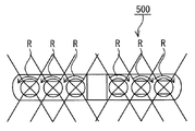
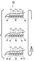
図6は、パトロールモードにおける警光灯500の動作状態の一例を示す模式図であり、図7は、パトロールモードにおけるサイレンアンプ200の複数のLED231の動作状態の一例を示す模式図である。
(Patrol mode)
FIG. 6 is a schematic diagram illustrating an example of an operation state of the
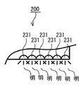
まず、警光灯制御システム100のサイレンアンプ200において『パトロールモード』が選定された場合、図4に示すように、警光灯500は、パターン1で点灯される。この場合、図6に示すように、警光灯500の内部が、矢印Rの方向に回転しつつ、明るさが周期的に変化する。
具体的には、警光灯500の内部のLED等の発光部のそれぞれが明暗を繰り返す。さらに、警光灯500の内部の反射鏡等を回転させることにより、矢印Rの方向に光を周囲に放光させることができる。
First, when “patrol mode” is selected in the
Specifically, each light emitting unit such as an LED inside the warning light 500 repeats light and dark. Furthermore, by rotating a reflecting mirror or the like inside the
また、『パトロールモード』において、サイレンは、『オフ』であり、サイレンアンプ200の複数のLED231は、『パターンA』で表示される。
ここで、図7に示すように、サイレンアンプ200の複数のLED231の『パターンA』は、明るさが周期的に変化する。
すなわち、サイレンアンプ200の複数のLED231の明るさが周期的に変化する。なお、複数のLED231の明るさは、明暗を繰り返すのではなく、オンオフを繰り返してもよい。
In the “patrol mode”, the siren is “off”, and the plurality of
Here, as shown in FIG. 7, the brightness of the “pattern A” of the plurality of
That is, the brightness of the plurality of
(緊急モード)
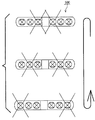
次に、図8は、緊急モードにおける警光灯500の動作状態の一例を示す模式図であり、図9は、緊急モードにおけるサイレンアンプ200の複数のLED231の動作状態の一例を示す模式図である。
(Emergency mode)
Next, FIG. 8 is a schematic diagram illustrating an example of an operation state of the
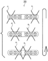
『緊急モード』が選定された場合、図4に示すように、警光灯500がパターン2で点灯される。
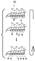
この場合、警光灯500は、ユニット毎に、点滅される。例えば、図8に示すように、両端部のユニットが2回点滅(フラッシュ)FLし、点滅し終えたユニットに隣接するユニットが、2回点滅FLし、最後に点滅FLし終えたユニットにさらに隣接するユニットが、2回点滅FLする。そして、当該点滅が繰り返される。
When the “emergency mode” is selected, the
In this case, the warning light 500 blinks for each unit. For example, as shown in FIG. 8, the units at both ends blink twice (flash) FL, the unit adjacent to the unit that has finished blinking blinks twice, and the last unit that has finished blinking FL further Adjacent units flash twice FL. Then, the blinking is repeated.
さらに、『緊急モード』において、サイレンは、『パターン1』の通常サイレンが吹鳴され、サイレンアンプ200の複数のLED231は、『パターンB』で表示される。
Further, in the “emergency mode”, the normal siren of “
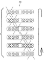
この場合、サイレンアンプ200の複数のLED231においては、図9に示すように、複数のLED231が2回点滅(フラッシュ)し、点滅し終えたLED231に隣接するLED231が2回点滅し、点滅し終えたLED231にさらに隣接するLED231が2回点滅する。同様に、LED231も点滅を繰り返す。
In this case, in the plurality of
(高警告モードA)
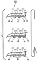
次いで、図10は、高警告モードAにおける警光灯500の動作状態の一例を示す模式図であり、図11は、高警告モードAにおけるサイレンアンプ200の複数のLED231の動作状態の一例を示す模式図である。
ここで、高警告モードAとは、渋滞を通過する際に、選択されるモードを意味する。
(High warning mode A)
10 is a schematic diagram illustrating an example of an operation state of the
Here, the high warning mode A means a mode that is selected when passing through a traffic jam.
『高警告モードA』が選定された場合、図4に示すように、警光灯500がパターン3で点灯される。この場合、図10に示すように、警光灯500は、内側ユニットから外側ユニットに向けて順次点灯を繰り返す。なお、パターン2の場合と異なり、2回点滅(フラッシュ)FLは行われない。
さらに、『高警告モードA』において、サイレンは、『パターン2』の通常サイレンよりも警告度の高い音が吹鳴され、サイレンアンプ200の複数のLED231は、『パターンC』で表示される。
When the “high warning mode A” is selected, the
Further, in the “high warning mode A”, the siren emits a sound having a higher warning level than the normal siren of “
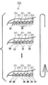
この場合、サイレンアンプ200の複数のLED231においては、図11に示すように、複数のLED231が内側から外側に向かって順次点灯を繰り返す。
In this case, in the plurality of
(高警告モードB)
次いで、図12は、高警告モードBにおける警光灯500の動作状態の一例を示す模式図であり、図13は、高警告モードBにおけるサイレンアンプ200の複数のLED231の動作状態の一例を示す模式図である。
ここで、高警告モードBとは、交差点へ侵入する際に選択されるモードを意味する。
(High warning mode B)
12 is a schematic diagram illustrating an example of an operation state of the
Here, the high warning mode B means a mode selected when entering the intersection.
『高警告モードB』が選定された場合、図4に示すように、警光灯500がパターン4で点灯される。この場合、図12に示すように、警光灯500は、ユニット全体が同時に2回点滅(フラッシュ)FLを繰り返す。
さらに、『高警告モードB』において、サイレンは、『パターン3』の通常サイレンおよび高警告サイレンAよりも警告度の高い音が吹鳴され、サイレンアンプ200の複数のLED231は、『パターンD』で表示される。
When the “high warning mode B” is selected, the
Further, in the “high warning mode B”, the siren is sounded with a higher warning level than the normal siren of “
この場合、サイレンアンプ200の複数のLED231においては、図13に示すように、複数のLED231が同時に2回点滅(フラッシュ)を繰り返す。
In this case, in the plurality of
(右折モード)
次いで、図14は、右折モードにおける警光灯500の動作状態の一例を示す模式図であり、図15は、右折モードにおけるサイレンアンプ200の複数のLED231の動作状態の一例を示す模式図である。
(Right turn mode)
14 is a schematic diagram illustrating an example of the operating state of the
『右折モード』が選定された場合、図4に示すように、警光灯500がパターン5で点灯される。この場合、図14に示すように、警光灯500は、消防車900の後方から前方に向いて視認した状態で、左側から右側に順に点滅を繰り返す。すなわち、右折する方向へ、警光灯500が指し示すように点滅する。
さらに、『右折モード』において、サイレンは、『直前のモード』で吹鳴され、サイレンアンプ200の複数のLED231は、『パターンE』で表示される。
When the “right turn mode” is selected, the
Further, in the “right turn mode”, the siren is blown in the “previous mode”, and the plurality of
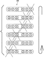
この場合、サイレンアンプ200の複数のLED231においては、図15に示すように、複数のLED231が左側から右側に順に点滅を繰り返す。
In this case, in the plurality of
(左折モード)
次いで、図16は、左折モードにおける警光灯500の動作状態の一例を示す模式図であり、図17は、左折モードにおけるサイレンアンプ200の複数のLED231の動作状態の一例を示す模式図である。
(Left turn mode)
16 is a schematic diagram illustrating an example of an operation state of the
『左折モード』が選定された場合、図4に示すように、警光灯500がパターン6で点灯される。この場合、図16に示すように、警光灯500は、消防車900の後方から前方に向いて視認した状態で、右側から左側に順に点滅を繰り返す。すなわち、左折する方向へ、警光灯500が指し示すように点滅する。
さらに、『左折モード』において、サイレンは、『直前のモード』で吹鳴され、サイレンアンプ200の複数のLED231は、『パターンF』で表示される。
When the “left turn mode” is selected, the
Further, in the “left turn mode”, the siren is sounded in the “previous mode”, and the plurality of
この場合、サイレンアンプ200の複数のLED231においては、図17に示すように、複数のLED231が右側から左側に順に点滅を繰り返す。
In this case, in the plurality of
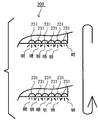
次いで、図18は、サイレンアンプ200の複数のLED231の他の例を示す模式図である。
Next, FIG. 18 is a schematic diagram illustrating another example of the plurality of
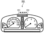
図18に示すように、複数のLED231は、例えば、運転席のインジケータ800内に設けられてもよい。なお、上記の実施の形態においては、運転席のインジケータ800について説明したが、これに限定されず、ハンドル部分、ボンネット部分など、消防車900の内部の任意の部分であってもよい。
As shown in FIG. 18, the plurality of
以上のように、本発明にかかる警光灯制御システム100においては、警光灯500を点灯制御するとともに、データテーブル700に基づいて、警光灯500の点灯制御を示す表示パターンを消防車900内の複数のLED231に示すことができ、ユーザは、消防車900内に居ながら、実際の警光灯500の点灯状態を認識することができる。
As described above, in the warning
また、サイレンアンプ200の複数のLED231を利用することにより、表示部を新たに設ける場合と異なり、省スペース化を図ることができる。
すなわち、本発明の実施の形態の複数のLED231は、警光灯500の状態を示す機能と、『パトロールモード』、『緊急モード』、『高警告モードA』、『高警告モードB』、『右折モード』、『左折モード』のいずれかを表示する表示機能とを兼ね備えているので、省スペース化を図ることができる。
Further, by using the plurality of
That is, the plurality of
さらに、右左折時においても、ウィンカー610、信号入力回路260からの信号に応じて、右左折それぞれの警光灯500の点灯と連動してサイレンアンプ200の複数のLED231に表示させることができる。
Further, even during a right / left turn, according to the signals from the
その結果、車外に出て警光灯500の稼動状況を確認することなく、車内にいながら警光灯500の稼動状況を確認することができる。
As a result, the operating status of the
なお、上記の例においては、各種モードにより警光灯500の点灯消灯、または複数のLED231の点灯消灯および明暗点灯について説明したが、上記の例に限定されず、警光灯500および複数のLED231の両者が連動していることが好ましく、点灯動作は、任意に変更することができることは、いうまでもない。
In the above example, lighting / extinguishing of the
なお、本実施の形態においては、各モードがそれぞれ異なるモードとして設定しているが、これらのうち複数個、例えば、パトロールモードおよび緊急モードは、サイレンアンプ200の複数のLED231において同じ表示であってもよい。
In the present embodiment, each mode is set as a different mode, but a plurality of, for example, a patrol mode and an emergency mode are the same display on the plurality of
本発明においては、警光灯500が『警光灯、散光式警光灯』に相当し、サイレンアンプ200が『操作部』に相当し、複数のLED231が『表示部、一機能表示』に相当し、パターン1からパターン6が『警光灯の点灯パターン』に相当し、パターンAからパターンFが『表示部の表示パターン』に相当し、図4のデータテーブル700が『データテーブル』に相当し、RAM241、EEPROM242が『記憶部』に相当し、CPU210が『制御部』に相当し、警光灯制御システム100が『警光灯制御システム』に相当し、図5のフローが『警光灯制御システムのプログラム』に相当し、ステップS5が『左側制御』に相当し、ステップS6が『右側制御』に相当し、ウィンカー610が『方向指示器』に相当し、消防車900が『車両』に相当する。
In the present invention, the
なお、本発明の『表示部』は、必ずしも本実施の形態で例示したような複数のLED231として実現される必要はない。例えば、サイレンアンプ200には、操作パネル270側に露出された表示画面が設けられていてもよい。そして、CPU210は、例えば、マイク、補助、音声、CH(チャンネル)、電源、交差点スイッチ、渋滞スイッチ、警光灯スイッチ、サイレンスイッチ等の各種のオンオフを示す情報を、表示画面に表示させてもよい。
また、CPU210は、警光灯500の点灯パターンを示すため、警光灯500またはそのユニットが点灯している状態を示すアイコンまたは図形の動画を表示画面に表示させてもよい。ここで、表示画面が本発明の『表示部』に相当する。また、表示画面に表示されるアイコンまたは図形の動画が『表示部の表示パターン』に相当する。
Note that the “display unit” of the present invention is not necessarily realized as a plurality of
Further, in order to indicate the lighting pattern of the
本発明の好ましい実施の形態は上記の通りであるが、本発明はそれだけに制限されない。本発明の精神と範囲から逸脱することのない様々な実施形態が他になされることは理解されよう。さらに、本実施形態において、本発明の構成による作用および効果を述べているが、これら作用および効果は、一例であり、本発明を限定するものではない。 The preferred embodiment of the present invention is as described above, but the present invention is not limited thereto. It will be understood that various other embodiments may be made without departing from the spirit and scope of the invention. Furthermore, in this embodiment, although the effect | action and effect by the structure of this invention are described, these effect | actions and effects are examples and do not limit this invention.
100 警光灯制御システム
200 サイレンアンプ
210 CPU
231 複数のLED
241 RAM
242 EEPROM
500 警光灯
610 ウィンカー
900 消防車
100 warning
231 LED
241 RAM
242 EEPROM
500
Claims (10)
ユーザの操作に基づいて、複数の操作信号を出力する操作部と、
車内において複数の表示を行うことが可能な表示部と、
前記警光灯の点灯パターンおよび前記表示部の表示パターンを、前記操作部の操作信号にそれぞれ対応付けたデータテーブルを記憶する記憶部と、
制御部と、を含み、
前記制御部は、前記操作部からの操作信号と前記データテーブルとによって対応付けられた前記警光灯の点灯パターンを用いて前記警光灯を制御するとともに、当該操作信号と前記データテーブルとによって対応付けられた前記表示部の表示パターンを用いて前記表示部を制御する、警光灯制御システム。 A warning light control system for controlling a warning light provided with a plurality of light emitting units,
An operation unit that outputs a plurality of operation signals based on a user operation;
A display unit capable of performing a plurality of displays in the vehicle;
A storage unit for storing a data table in which the lighting pattern of the warning light and the display pattern of the display unit are respectively associated with the operation signal of the operation unit;
A control unit,
The control unit controls the warning light using the lighting pattern of the warning light associated with the operation signal from the operation unit and the data table, and uses the operation signal and the data table. The warning light control system which controls the said display part using the display pattern of the said display part matched.
前記制御部は、前記検知部の検知結果に応じて、前記警光灯の点灯パターンを前記方向指示器用の点灯パターンに変化させるとともに、前記警光灯の点灯パターンに応じて、前記表示部の表示パターンを方向指示器用の表示パターンに変化させる、請求項1から4のいずれか1項に記載の警光灯制御システム。 It further includes a detector that detects the output of the direction indicator,
The control unit changes the lighting pattern of the warning light to the lighting pattern for the direction indicator according to the detection result of the detection unit, and according to the lighting pattern of the warning light, The warning light control system of any one of Claim 1 to 4 which changes a display pattern into the display pattern for direction indicators.
前記表示部の前記発光素子および前記警光灯の前記発光部は、車両に取りつけられた状態において、少なくともそれぞれ左右方向に沿って配列する部分を有し、
前記制御部は、前記検知部の検知結果に基づき、前記方向指示器が指示する向きが左であると判定したことを条件として、前記複数の発光素子の右側から左側へ順次点灯または明度を増加する表示パターンによって前記表示部を制御するとともに、複数の前記発光部が右側から左側へ順次点灯または明度を増加する発光パターンによって前記警光灯を制御する左側制御と、
前記方向指示器が指示する向きが右であると判定したことを条件として、前記複数の発光素子が左側から右側へ順次点灯または明度を増加する表示パターンによって前記表示部を制御するとともに、前記複数の発光部が左側から右側へ順次点灯または明度を増加する発光パターンによって前記警光灯を制御する右側制御とを含む、請求項5に記載の警光灯制御システム。 The display unit includes a plurality of light emitting elements,
The light-emitting element of the display unit and the light-emitting unit of the warning light have at least portions arranged in the left-right direction in a state where the light-emitting element is attached to a vehicle,
The control unit sequentially turns on or increases the brightness from the right side to the left side of the plurality of light emitting elements on the condition that the direction indicated by the direction indicator is determined to be left based on the detection result of the detection unit. The left side control for controlling the warning light by a light emission pattern in which the display unit is controlled by a display pattern to be controlled, and a plurality of the light emitting units are sequentially lit from the right side to the left side or the brightness is increased.
The display unit is controlled by a display pattern in which the plurality of light emitting elements are sequentially turned on from the left side to the right side or the brightness is increased on the condition that the direction indicated by the direction indicator is right. 6. The warning light control system according to claim 5, further comprising: a right side control that controls the warning light by a light emission pattern in which the light emitting unit is sequentially turned on from the left side to the right side or increases in brightness.
複数の発光部が配設された警光灯と、を含む車両。 The warning light control system according to any one of claims 1 to 8,
A vehicle including a warning light provided with a plurality of light emitting units.
ユーザの操作に基づいて、複数の操作信号を出力する操作ステップと、
車内において複数の表示を行うことが可能な表示ステップと、
前記警光灯の点灯パターンおよび前記表示ステップの表示パターンを、前記操作ステップの操作信号にそれぞれ対応付けたデータテーブルを記憶する記憶ステップと、
制御ステップと、を含み、
前記制御ステップは、前記操作ステップからの操作信号と前記データテーブルとによって対応付けられた前記警光灯の点灯パターンを用いて前記警光灯を制御するとともに、当該操作信号と前記データテーブルとによって対応付けられた前記表示ステップの表示パターンを用いて前記表示ステップを制御する、警光灯制御システムのプログラム。 A warning light control system program for controlling a warning light provided with a plurality of light emitting units,
An operation step for outputting a plurality of operation signals based on a user operation;
A display step capable of performing a plurality of displays in the vehicle;
A storage step of storing a data table in which the lighting pattern of the warning light and the display pattern of the display step are respectively associated with the operation signal of the operation step;
A control step,
The control step controls the warning light using a lighting pattern of the warning light associated with the operation signal from the operation step and the data table, and uses the operation signal and the data table. The program of the warning light control system which controls the said display step using the display pattern of the said display step matched.
Priority Applications (1)
| Application Number | Priority Date | Filing Date | Title |
|---|---|---|---|
| JP2014103468A JP5979449B2 (en) | 2014-05-19 | 2014-05-19 | Warning light control system, vehicle including warning light control system, program for warning light control system |
Applications Claiming Priority (1)
| Application Number | Priority Date | Filing Date | Title |
|---|---|---|---|
| JP2014103468A JP5979449B2 (en) | 2014-05-19 | 2014-05-19 | Warning light control system, vehicle including warning light control system, program for warning light control system |
Publications (2)
| Publication Number | Publication Date |
|---|---|
| JP2015217841A true JP2015217841A (en) | 2015-12-07 |
| JP5979449B2 JP5979449B2 (en) | 2016-08-24 |
Family
ID=54777592
Family Applications (1)
| Application Number | Title | Priority Date | Filing Date |
|---|---|---|---|
| JP2014103468A Active JP5979449B2 (en) | 2014-05-19 | 2014-05-19 | Warning light control system, vehicle including warning light control system, program for warning light control system |
Country Status (1)
| Country | Link |
|---|---|
| JP (1) | JP5979449B2 (en) |
Cited By (4)
| Publication number | Priority date | Publication date | Assignee | Title |
|---|---|---|---|---|
| JP2019089473A (en) * | 2017-11-15 | 2019-06-13 | 株式会社トヨタカスタマイジング&ディベロップメント | Notification device for emergency vehicle |
| JP2019206225A (en) * | 2018-05-28 | 2019-12-05 | 株式会社大阪サイレン製作所 | Warning lamp control system |
| JP2021070921A (en) * | 2019-10-29 | 2021-05-06 | 酒井重工業株式会社 | Alarm device of construction vehicle |
| JP2023124698A (en) * | 2022-02-25 | 2023-09-06 | 株式会社パトライト | Light-diffusing type warning lamp system and vehicle equipped with the same |
Citations (4)
| Publication number | Priority date | Publication date | Assignee | Title |
|---|---|---|---|---|
| JPS57151445A (en) * | 1981-03-11 | 1982-09-18 | Matsushita Electric Ind Co Ltd | Indicator of operation for automobile, etc. |
| JPS6439587U (en) * | 1987-08-28 | 1989-03-09 | ||
| JP2006123813A (en) * | 2004-10-29 | 2006-05-18 | Patoraito:Kk | Warning light system |
| JP2008085476A (en) * | 2006-09-26 | 2008-04-10 | Patoraito:Kk | Alarm tone generator |
-
2014
- 2014-05-19 JP JP2014103468A patent/JP5979449B2/en active Active
Patent Citations (4)
| Publication number | Priority date | Publication date | Assignee | Title |
|---|---|---|---|---|
| JPS57151445A (en) * | 1981-03-11 | 1982-09-18 | Matsushita Electric Ind Co Ltd | Indicator of operation for automobile, etc. |
| JPS6439587U (en) * | 1987-08-28 | 1989-03-09 | ||
| JP2006123813A (en) * | 2004-10-29 | 2006-05-18 | Patoraito:Kk | Warning light system |
| JP2008085476A (en) * | 2006-09-26 | 2008-04-10 | Patoraito:Kk | Alarm tone generator |
Cited By (6)
| Publication number | Priority date | Publication date | Assignee | Title |
|---|---|---|---|---|
| JP2019089473A (en) * | 2017-11-15 | 2019-06-13 | 株式会社トヨタカスタマイジング&ディベロップメント | Notification device for emergency vehicle |
| JP2019206225A (en) * | 2018-05-28 | 2019-12-05 | 株式会社大阪サイレン製作所 | Warning lamp control system |
| JP2021070921A (en) * | 2019-10-29 | 2021-05-06 | 酒井重工業株式会社 | Alarm device of construction vehicle |
| JP7274399B2 (en) | 2019-10-29 | 2023-05-16 | 酒井重工業株式会社 | construction vehicle alarm |
| JP2023124698A (en) * | 2022-02-25 | 2023-09-06 | 株式会社パトライト | Light-diffusing type warning lamp system and vehicle equipped with the same |
| JP7488841B2 (en) | 2022-02-25 | 2024-05-22 | 株式会社パトライト | Diffused warning light system and vehicle equipped with same |
Also Published As
| Publication number | Publication date |
|---|---|
| JP5979449B2 (en) | 2016-08-24 |
Similar Documents
| Publication | Publication Date | Title |
|---|---|---|
| JP7011901B2 (en) | Control device and lighting system | |
| JP5979449B2 (en) | Warning light control system, vehicle including warning light control system, program for warning light control system | |
| JP2015202700A (en) | Alert device | |
| US9789822B2 (en) | Mirror controller unit for emergency vehicle warning devices | |
| JP5968389B2 (en) | Button selection trace light indicator | |
| JP5256266B2 (en) | Combined alarm | |
| JP2005297618A (en) | Multiplex informing device of instrument panel for vehicle | |
| KR101091829B1 (en) | Variable brake lights | |
| JP2016124503A (en) | Direction indicating device for vehicle | |
| JP5777021B2 (en) | Light control system and vehicle | |
| JP6502700B2 (en) | In-vehicle lighting system | |
| JP2005331493A (en) | Display device for vehicle | |
| KR20180080922A (en) | Traffic lights that simultaneously display lights and flashes | |
| JP4820064B2 (en) | Combined alarm | |
| JP4786877B2 (en) | Alarm | |
| KR101616110B1 (en) | Apparatus for controlling cluster of vehicle and method thereof | |
| JP3201214U (en) | vehicle | |
| JP5062124B2 (en) | Vehicle display device | |
| JP2011000942A (en) | State display device for vehicle | |
| JP2024132509A (en) | Lighting control system, evaluation system, evaluation method, and program | |
| JP2004090810A (en) | Display unit for vehicle | |
| JP2009226963A (en) | Vehicle light control system | |
| KR100839490B1 (en) | Warning lights for emergency vehicles with text display | |
| JP2003191771A (en) | Instrument device for vehicle | |
| KR200415871Y1 (en) | Vehicle deceleration display device |
Legal Events
| Date | Code | Title | Description |
|---|---|---|---|
| A977 | Report on retrieval |
Free format text: JAPANESE INTERMEDIATE CODE: A971007 Effective date: 20160114 |
|
| A131 | Notification of reasons for refusal |
Free format text: JAPANESE INTERMEDIATE CODE: A131 Effective date: 20160128 |
|
| A521 | Request for written amendment filed |
Free format text: JAPANESE INTERMEDIATE CODE: A523 Effective date: 20160323 |
|
| TRDD | Decision of grant or rejection written | ||
| A01 | Written decision to grant a patent or to grant a registration (utility model) |
Free format text: JAPANESE INTERMEDIATE CODE: A01 Effective date: 20160630 |
|
| A61 | First payment of annual fees (during grant procedure) |
Free format text: JAPANESE INTERMEDIATE CODE: A61 Effective date: 20160713 |
|
| R150 | Certificate of patent or registration of utility model |
Ref document number: 5979449 Country of ref document: JP Free format text: JAPANESE INTERMEDIATE CODE: R150 |
|
| R250 | Receipt of annual fees |
Free format text: JAPANESE INTERMEDIATE CODE: R250 |
|
| R250 | Receipt of annual fees |
Free format text: JAPANESE INTERMEDIATE CODE: R250 |
|
| R250 | Receipt of annual fees |
Free format text: JAPANESE INTERMEDIATE CODE: R250 |
|
| R250 | Receipt of annual fees |
Free format text: JAPANESE INTERMEDIATE CODE: R250 |
|
| R250 | Receipt of annual fees |
Free format text: JAPANESE INTERMEDIATE CODE: R250 |
|
| R250 | Receipt of annual fees |
Free format text: JAPANESE INTERMEDIATE CODE: R250 |
|
| R250 | Receipt of annual fees |
Free format text: JAPANESE INTERMEDIATE CODE: R250 |