JP2015211706A - Medical double-chamber container - Google Patents
Medical double-chamber container Download PDFInfo
- Publication number
- JP2015211706A JP2015211706A JP2014094497A JP2014094497A JP2015211706A JP 2015211706 A JP2015211706 A JP 2015211706A JP 2014094497 A JP2014094497 A JP 2014094497A JP 2014094497 A JP2014094497 A JP 2014094497A JP 2015211706 A JP2015211706 A JP 2015211706A
- Authority
- JP
- Japan
- Prior art keywords
- chamber
- end wall
- medical
- separate
- main
- Prior art date
- Legal status (The legal status is an assumption and is not a legal conclusion. Google has not performed a legal analysis and makes no representation as to the accuracy of the status listed.)
- Pending
Links
Images
Abstract
Description
本発明は医療用2室容器に関する。 The present invention relates to a medical two-chamber container.
複数の薬剤を混合した状態で投与する場合、薬剤の組み合わせによっては、メイラード反応等により変質が起こる場合があることから、医療現場で使用直前に混合して投与することが行われ、2室容器が使用されている。2室容器は熱可塑性樹脂フィルムのヒートシール加工により製袋化され、基本的には容器内部が弱ヒートシール部で2室に区分された構造を備えている。容器の使用の際は、一定の外力を加えることにより弱ヒートシール部を剥離し、各室の薬剤を混合する。 When administering a plurality of drugs in a mixed state, depending on the combination of the drugs, alteration may occur due to Maillard reaction, etc., so mixing is performed immediately before use at a medical site, and the two-chamber container is used. Is used. The two-chamber container is made into a bag by heat sealing processing of a thermoplastic resin film, and basically has a structure in which the inside of the container is divided into two chambers by a weak heat seal portion. When the container is used, the weak heat seal part is peeled off by applying a constant external force, and the chemicals in each chamber are mixed.
ところで、従来の2室容器は各室の薬液注入口が異なる方向に設けられている(例えば特許文献1の図8の充填予定部18、19)。そのため、製袋充填機による薬液充填工程では容器を回転させて2工程に分けて充填する必要があり、充填操作が煩雑になり設備コストが高額となるという問題がある。 By the way, the conventional two-chamber container is provided in the direction where the chemical | medical solution injection port of each chamber differs (for example, the filling plan parts 18 and 19 of FIG. 8 of patent document 1). Therefore, in the chemical solution filling process by the bag making and filling machine, it is necessary to fill the container in two steps by rotating the container, and there is a problem that the filling operation becomes complicated and the equipment cost becomes high.
薬液排出口を薬液注入口として利用することにより、薬液注入口を一方の室のみに設けた2室容器が知られている(特許文献2の図1の注排口5、充填口6)。しかしながら、容器の使用の前に薬液排出口を開放して取り扱うことは、厳しい滅菌処理が課せられる医療用途の観点から好ましいことではない。 There is known a two-chamber container in which a chemical solution injection port is provided only in one chamber by using the chemical solution discharge port as a chemical solution injection port (pour-out port 5 and filling port 6 in FIG. 1 of Patent Document 2). However, it is not preferable to open the chemical solution discharge port before using the container from the viewpoint of medical use in which severe sterilization treatment is imposed.
上述のように従来の医療用2室容器においては、薬液注入口の取り付け位置は余り考慮されていない情況であるが、各室の薬液注入方向が同一方向であるならば、設備コストの低減が図られるため、製袋充填機の新設における利点は大きい。 As described above, in the conventional medical two-chamber container, the installation position of the chemical solution injection port is not considered much, but if the injection direction of the chemical solution in each chamber is the same direction, the equipment cost can be reduced. Therefore, the advantages of the new bag making and filling machine are great.
本発明は、上記実情に鑑みなされたものであり、その目的は、各室の薬液注入方向が同一方向であり、しかも、各室の薬剤を混合して排出する際に障害となる箇所がなく、点滴や透析用途のように比較的大容量の薬液を充填しているにも拘わらず、手押しや両手絞り等の簡単な操作で確実に弱ヒートシール部を剥離し得る、医療用2室容器を提供することにある。 The present invention has been made in view of the above circumstances, and the purpose thereof is that the injection direction of the chemical solution in each chamber is the same, and there is no place that becomes an obstacle when mixing and discharging the drug in each chamber. A medical two-chamber container that can reliably remove the weak heat-sealed parts by simple operations such as hand-pushing and two-handed drawing even though it is filled with a relatively large volume of chemical solution, such as for infusion or dialysis. Is to provide.
すなわち、本発明の要旨は、熱可塑性樹脂フィルムのヒートシール加工により製袋化され且つ本室の内部に別室を備えた医療用2室容器であって、別室は、本室の一端壁に接続して対向する他端壁に至る途中までの間に設けられた側部と当該側部に接すると共に対向する本室の一端壁に接続して設けられた底部とによって本室と区分され、本室および別室の同一方向の端部にはそれぞれ薬液注入口が設けられ、本室の下部の一端部には薬液排出口が設けられ、別室の側部を形成するヒートシール部の幅は5〜20mmであり強度は25N/15mm以上、別室の底部を形成するヒートシール部の幅は5〜20mmであり強度は2〜10N/15mmであり、使用時の条件として、本室の容量は最大充填量に対して30〜90%の範囲で且つ350〜5,000mlであり、別室の容量は最大充填量に対して30〜90%の範囲で且つ75〜1,600mlであることを特徴とする医療用2室容器に存する。 That is, the gist of the present invention is a medical two-chamber container which is made into a bag by heat sealing processing of a thermoplastic resin film and has a separate chamber inside the main chamber, and the separate chamber is connected to one end wall of the main chamber. And separated from the main room by a side part provided halfway up to the opposite other end wall and a bottom part provided in contact with the side part and connected to one end wall of the opposing main room. A chemical solution inlet is provided at each end of the chamber and the separate chamber in the same direction, a chemical discharge port is provided at one end of the lower part of the main chamber, and the width of the heat seal part forming the side of the separate chamber is 5 to 5. It is 20mm, the strength is 25N / 15mm or more, the width of the heat seal part that forms the bottom of the separate chamber is 5-20mm, and the strength is 2-10N / 15mm. In the range of 30-90% of the quantity and 3 A 0~5,000Ml, Separate volume resides in the medical two-chamber container, wherein a and 75~1,600ml in the range of 30% to 90% relative to the maximum loading.
本発明によれば前記の課題が達成される。 According to the present invention, the above-described problems are achieved.
以下、本発明を図1に基づいて詳細に説明する。 Hereinafter, the present invention will be described in detail with reference to FIG.
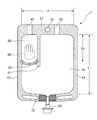
本発明の医療用2室容器(1)は、熱可塑性樹脂フィルムのヒートシール加工により製袋化され且つ本室(10)の内部に別室(20)を備えた構造である。ここで、本室(10)とは、熱可塑性樹脂フィルムを平面視した際の外周縁部に形成された一定幅のヒートシール部(内壁)で囲まれた領域を意味する。なお、この領域の一部は別室(20)によって占有される。上記のヒートシール部の幅は通常5〜20mmである。なお、このヒートシール部の幅は、ヒートシール欠陥をなくしてピンホール発生を防止する観点から決定された値である。 The medical two-chamber container (1) of the present invention has a structure in which a bag is made by heat sealing a thermoplastic resin film and a separate chamber (20) is provided inside the main chamber (10). Here, the main chamber (10) means a region surrounded by a heat seal portion (inner wall) having a certain width formed on the outer peripheral edge when the thermoplastic resin film is viewed in plan view. A part of this area is occupied by a separate room (20). The width | variety of said heat seal part is 5-20 mm normally. Note that the width of the heat seal portion is a value determined from the viewpoint of eliminating a heat seal defect and preventing the occurrence of pinholes.
医療用2室容器(1)の全体の平面形状は略長方形であり、内壁を形成するヒートシール部を除く内寸として、縦方向の長さは通常200〜560mm、横方向の長さは通常200〜350mmであり、縦横比は通常1.0〜1.8である。なお、本明細書において、「縦方向」とは、医療用2室容器(1)を吊り下げた際の上下方向を意味し、「横方向」は当該「縦方向」を横切る方向を意味する。本発明の医療用2室容器(1)を吊り下げて使用する場合は、通常、容器本体の上部に中空の吊り下げ孔(70)が設けられる。 The overall planar shape of the medical two-chamber container (1) is substantially rectangular, and the length in the vertical direction is usually 200 to 560 mm, and the length in the horizontal direction is usually the inner dimension excluding the heat seal part forming the inner wall. It is 200 to 350 mm, and the aspect ratio is usually 1.0 to 1.8. In this specification, “vertical direction” means a vertical direction when the medical two-chamber container (1) is suspended, and “lateral direction” means a direction crossing the “vertical direction”. . When the medical two-chamber container (1) of the present invention is suspended and used, a hollow suspension hole (70) is usually provided in the upper part of the container body.
また、一般に、取り扱いを容易にするために、角部は図示するようにR形状となされている。特に、内壁の角部のR形状は、角部における薬液の滞留をなくして排出を容易にする利点がある。R形状の曲率半径は、通常R5〜20mm、好ましくはR5〜15mmである。 In general, the corners have an R shape as shown in order to facilitate handling. In particular, the R shape of the corner portion of the inner wall has an advantage of facilitating discharge by eliminating the retention of the chemical solution at the corner portion. The radius of curvature of the R shape is usually R5 to 20 mm, preferably R5 to 15 mm.
別室(20)は、本室(10)の上部の一端壁(11)に接続して対向する下部の一端壁(12)に至る途中までの間に設けられた側部(21)と当該側部に接すると共に対向する本室(10)の左側の一端壁(13)に接続して設けられた底部(22)とによって本室(10)と区分されている。従って、後述する薬液排出口(50)が設けられる本室(10)の底部は、各室の薬剤を混合して排出する際に障害となる箇所がなく、完全にフラットである。なお、別室(20)の底部(22)の形成には本室(10)の右側の一端壁(14)を利用してもよい。 The separate chamber (20) is connected to the upper end wall (11) of the upper portion of the main chamber (10), and is provided between the side portion (21) provided on the way to the opposite lower end wall (12) and the side. The main room (10) is separated from the main room (10) by a bottom part (22) provided in contact with the opposite end wall (13) on the left side of the main room (10). Therefore, the bottom of the main chamber (10) provided with a chemical solution outlet (50) to be described later is completely flat without any obstacles when mixing and discharging the drugs in each chamber. Note that the right end wall (14) of the main chamber (10) may be used to form the bottom (22) of the separate chamber (20).
別室(20)の底部(22)の形状は、図示した例では円弧形状であるが、直線形状であってもよい。また、底部(22)の本室(10)の左側の一端壁(13)に接続する位置は、図示した例では、側部(21)と略同一長さの位置であるが、それよりも長い長さの位置であっても短い長さの位置であってもよい。 The shape of the bottom (22) of the separate chamber (20) is an arc shape in the illustrated example, but may be a linear shape. In addition, in the illustrated example, the position where the bottom (22) is connected to the left end wall (13) of the main chamber (10) is substantially the same length as the side (21). It may be a long position or a short position.
別室(20)の側部(21)の長さ(L2)は、本室(10)の上部の一端壁(11)と対向する下部の一端壁(12)の間の長さ(L1)に対する比率(L2/L1)として、通常0.4〜0.9、好ましくは0.5〜0.7である。一方、底部(22)の長さは、底部(22)と側部(21)の長さとによって別室(20)の容量が決定されるため、別室(20)の後述する薬液充填容量を満足するように選ばれる。 The length (L2) of the side part (21) of the separate chamber (20) is relative to the length (L1) between the upper end wall (11) of the main chamber (10) and the lower end wall (12) facing the lower end wall (12). The ratio (L2 / L1) is usually 0.4 to 0.9, preferably 0.5 to 0.7. On the other hand, since the capacity of the separate chamber (20) is determined by the length of the bottom (22) and the side (21), the length of the bottom (22) satisfies the later-described chemical solution filling capacity of the separate chamber (20). So chosen.
後述するように、別室(20)の側部(21)を形成するヒートシール部は強ヒートシールされ、容器の使用の際に加えられる外力によっても剥離しない。従って、別室(20)の側部(21)の長さが上記の比率範囲を超える場合は、側部(21)が本室(10)の下部の一端壁(12)に近くなり過ぎる。その結果、別室(20)に充填された薬液の排出領域が狭くなる。 As will be described later, the heat seal portion forming the side portion (21) of the separate chamber (20) is strongly heat sealed, and does not peel off even by an external force applied when the container is used. Therefore, when the length of the side portion (21) of the separate chamber (20) exceeds the above ratio range, the side portion (21) becomes too close to the one end wall (12) at the lower portion of the main chamber (10). As a result, the discharge area of the chemical solution filled in the separate chamber (20) is narrowed.
一方、後述するように、別室(20)の底部(22)を形成するヒートシール部は弱ヒートシールされ、容器の使用の際に加えられる外力によっても剥離する。従って、別室(20)の側部(21)の長さが上記の比率範囲未満の場合は、別室(20)の後述する薬液充填容量を満足させる必要のため、底部(22)の長さを相当に大きくする必要がある。その結果、薬液を充填した医療用2室容器(1)の取り扱いの際に底部(22)が剥離して薬液が混合する恐れがある。 On the other hand, as will be described later, the heat seal part forming the bottom part (22) of the separate chamber (20) is weakly heat-sealed and is peeled off by an external force applied when the container is used. Therefore, when the length of the side portion (21) of the separate chamber (20) is less than the above ratio range, the length of the bottom portion (22) is set to satisfy the later-described chemical solution filling capacity of the separate chamber (20). It needs to be quite large. As a result, when the medical two-chamber container (1) filled with the chemical solution is handled, the bottom (22) may be peeled off and the chemical solution may be mixed.
本室(10)の上部の一端壁(11)に接続する別室(20)の側部(21)の位置は、上部の一端壁(11)の全長(シール部を除く内寸としての横方向の長さ:通常200〜350mm)(L3)に対し、通常0.2〜0.6倍の範囲、好ましくは0.3〜0.5(半分)の位置である。斯かる範囲は、本室(10)と別室(20)とにそれぞれ設けられる後述する薬液注入口の取り付け位置や各室に薬液が充填された状態でのバランスが良好である。 The position of the side portion (21) of the separate chamber (20) connected to the upper end wall (11) of the main chamber (10) is the total length of the upper end wall (11) (the horizontal direction as the inner dimension excluding the seal portion). Is usually in the range of 0.2 to 0.6 times, preferably 0.3 to 0.5 (half) relative to (L3). Such a range has a good balance in a state in which a chemical solution injection port (described later) provided in each of the main chamber (10) and the separate chamber (20) is installed and in a state where each chamber is filled with the chemical solution.
本室(10)及び別室(20)の同一方向の端部にはそれぞれ薬液注入口(30)、(40)が設けられ、本室(10)の下部の一端部(12)には薬液排出口(50)が設けられる。薬液注入口(30)、(40)は、熱可塑性樹脂フィルムのヒートシール加工による製袋化の際に、未シールにすることにより開口させたものであり、薬液の充填後にヒートシール加工により封止される。一方、薬液排出口(50)には、図示を簡略化しているが、通常、熱可塑性樹脂の成形品で構成された排出ポートが使用される。排出ポートは、筒状に形成され、その内部空洞は一端側で本室(10)に開口し、他端にはゴム栓が設けられている。薬液排出口(50)は、通常、熱可塑性樹脂フィルムのヒートシール加工による製袋化の際に本室(10)のポートシール部に設けられる。 Chemical solution inlets (30) and (40) are respectively provided at the ends of the main chamber (10) and the separate chamber (20) in the same direction, and the chemical solution discharge port is provided at the lower end (12) of the main chamber (10). An outlet (50) is provided. The chemical solution inlets (30) and (40) are opened by unsealing when the thermoplastic resin film is made into a bag by heat sealing, and sealed by heat sealing after filling with the chemical. Stopped. On the other hand, although the illustration is simplified for the chemical solution discharge port (50), a discharge port made of a molded product of a thermoplastic resin is usually used. The discharge port is formed in a cylindrical shape, and its internal cavity opens to the main chamber (10) on one end side, and a rubber plug is provided on the other end. The chemical solution discharge port (50) is usually provided in the port seal portion of the main chamber (10) when making a bag by heat sealing the thermoplastic resin film.
別室(20)の側部(21)を形成するヒートシール部の幅は5〜20mmであり強度は25N/15mm以上、別室(20)の底部(22)を形成するヒートシール部の幅は5〜20mmであり強度は2〜10N/15mmである。 The width of the heat seal portion forming the side portion (21) of the separate chamber (20) is 5 to 20 mm, the strength is 25 N / 15 mm or more, and the width of the heat seal portion forming the bottom portion (22) of the separate chamber (20) is 5 It is ˜20 mm and the strength is 2 to 10 N / 15 mm.
本発明においては、後述する使用時の条件に従い、点滴や透析用途のように比較的大容量の薬液を本室(10)と別室(20)とに充填する。そして、手押しや両手絞り等の簡単な操作で別室(20)の底部(22)を形成するヒートシール部のみを剥離し、別室(20)の薬液を排出させて本室(10)の薬液と混合する。上記の各ヒートシール強度は、後述する使用時の条件の下に上記の目的を確実に達成するために決定された値である。また、ヒートシール部の幅は、ヒートシール欠陥をなくしてピンホール発生を防止する観点から決定された値である。なお、ヒートシール強度は、JISZ1707「食品包装用プラスチックフィルム通則」による180°剥離強度を意味する。 In the present invention, a relatively large volume of chemical solution is filled into the main chamber (10) and the separate chamber (20) as in the case of drip or dialysis according to the conditions at the time of use described later. Then, only the heat seal part that forms the bottom (22) of the separate chamber (20) is peeled off by a simple operation such as hand pressing or two-handed squeezing, and the chemical solution in the separate chamber (20) is discharged to remove the chemical solution in the main chamber (10). Mix. Each of the above heat seal strengths is a value determined in order to reliably achieve the above object under the conditions at the time of use described later. Moreover, the width | variety of a heat seal part is a value determined from a viewpoint which eliminates a heat seal defect and prevents pinhole generation | occurrence | production. The heat seal strength means a 180 ° peel strength according to JISZ1707 “Plastic Film for Food Packaging”.
前記のヒートシール強度の差は、ヒートシール時のシール条件(上下シールバー温度、シール時間、シール圧力など)によって適宜調整することが出来る。 The difference in the heat seal strength can be appropriately adjusted depending on the seal conditions (upper and lower seal bar temperature, seal time, seal pressure, etc.) during heat seal.
使用時の条件として、本室(10)の容量は最大充填量に対して30〜90%の範囲で且つ350〜5,000mlであり、別室(20)の容量は最大充填量に対して30〜90%の範囲で且つ75〜1,600mlである。最大充填量に対する割合が上記範囲を超える場合は、薬液充填状態の外観形状が膨張形状となり、輸送時に各室を区分する弱シール部に応力が掛り、誤って開通する可能性が生じる。最大充填量に対する割合が上記範囲未満の場合は、医療用2室容器の利用率の点で経済的ではない。最大充填量に対する割合の好ましい範囲は60〜80%である。なお、上記の各薬液充填(ml)は点滴や透析用途の観点から決定された容量である。また、上記の最大充填量とは、予定している仕様の2室に沿った試験容器を作成し、注入口から各室に収容し得る最大量の水を入れた後にそれぞれ取り出して測定した水の容量を意味する。 As conditions for use, the capacity of the main chamber (10) is in the range of 30 to 90% with respect to the maximum filling amount and 350 to 5,000 ml, and the capacity of the separate chamber (20) is 30 with respect to the maximum filling amount. It is in the range of ˜90% and 75 to 1,600 ml. When the ratio with respect to the maximum filling amount exceeds the above range, the appearance shape in the chemical solution filling state becomes an expanded shape, and stress is applied to the weak seal portion that divides each chamber during transportation, and there is a possibility that it is opened erroneously. When the ratio with respect to the maximum filling amount is less than the above range, it is not economical in terms of the utilization rate of the medical two-chamber container. The preferable range of the ratio with respect to the maximum filling amount is 60 to 80%. In addition, each said chemical | medical solution filling (ml) is a capacity | capacitance determined from the viewpoint of drip or a dialysis use. In addition, the above-mentioned maximum filling amount refers to the water measured by preparing a test container along two chambers of the planned specifications, taking out the maximum amount of water that can be accommodated in each chamber from the injection port, and taking out each. Means capacity.
熱可塑性樹脂フィルムとしては、ヒートシール加工可能である限り、特に制限されない。好ましい熱可塑性樹脂は、ポリオレフィン系樹脂であり、その具体例としては、ポリエチレン、ポリプロピレン、エチレン−プロピレン共重合体、エチレン−ブテン−1共重合体などが挙げられる。これらの中では、欧米等の諸外国で標準的に設定されている121℃以上の高圧蒸気滅菌処理が可能であるとの観点からポリプロピレン系樹脂が好ましい。特に、無変成のポリオレフィン系樹脂は、無極性であるため、薬液の吸着が非常に少ないことも期待される。 The thermoplastic resin film is not particularly limited as long as it can be heat-sealed. A preferred thermoplastic resin is a polyolefin resin, and specific examples thereof include polyethylene, polypropylene, an ethylene-propylene copolymer, an ethylene-butene-1 copolymer, and the like. Among these, a polypropylene resin is preferable from the viewpoint that high-pressure steam sterilization at 121 ° C. or higher, which is standardly set in various countries such as Europe and the United States, is possible. In particular, non-modified polyolefin resins are non-polar, and therefore are expected to have very little chemical solution adsorption.
熱可塑性樹脂フィルムは単層フィルムであっても多層フィルムであってもよいが、多層フィルムが好ましい。 The thermoplastic resin film may be a single layer film or a multilayer film, but a multilayer film is preferred.
なお、上記のポリプロピレン樹脂としては、プロピレンホモポリマー、ランダムポリプロピレン、ブロックポリプロピレン等が挙げられる。プロピレンと共重合可能なα−オレフィンとしては、エチレン、ブテン−1、ペンテン−1、ヘキセン−1等が挙げられる。また、本発明の効果を損なわない範囲でポリプロピレン樹脂にポリオレフィン系エラストマーをブレンドしてもよい。 In addition, as said polypropylene resin, a propylene homopolymer, random polypropylene, block polypropylene, etc. are mentioned. Examples of the α-olefin copolymerizable with propylene include ethylene, butene-1, pentene-1, and hexene-1. Moreover, you may blend a polyolefin-type elastomer with a polypropylene resin in the range which does not impair the effect of this invention.
熱可塑性樹脂フィルムの厚さは、単層および多層の何れの場合でも、通常50〜300μm、好ましくは100〜200μmである。厚さが50μm未満の場合は、取り扱い(輸送、保管、高温滅菌など)の際に破断し、300μmを超える場合は、容器の柔軟性が失われて自己排液性が悪くなる。 The thickness of the thermoplastic resin film is usually 50 to 300 μm, preferably 100 to 200 μm, regardless of whether it is a single layer or a multilayer. When the thickness is less than 50 μm, it breaks during handling (transportation, storage, high-temperature sterilization, etc.), and when it exceeds 300 μm, the flexibility of the container is lost and the self-drainage becomes worse.
熱可塑性樹脂フィルムの製造方法は、特に限定されず、Tダイ成形、インフレーション成形など、一般の熱可塑性樹脂に用いられる方法により製造されるが、インフレーション法が好ましい。インフレーション法フィルムは、環状ダイからチューブ状として得られるが、冷却後直ちにニップロールにて平坦化される。従って、密着状態で重ね合わされた2枚のフィルムの容器内面相当部分はクリーン状態に維持されている。多層インフレーション成形の場合は、特に、共押出環状ダイを使用した下向水冷インフレーション成形法が好適である。斯かる方法は、通常、環状ダイの下方にサイズ用リングが内部に備えられた水槽を配置し、当該水槽の下方に安内板とニップロールとを順次に配置して成る設備を使用し、そして、環状ダイから複数種類の原料樹脂を実質的に延伸が起こらないように共押し出しし、水槽内サイズ用リングの間を通過させて水冷却した後、多層フィルムの円筒体を、安内板を通してニップロールに供給して折り畳み、チューブ状フィルムとして巻き取る方法である。 The method for producing the thermoplastic resin film is not particularly limited, and the thermoplastic resin film is produced by a method used for general thermoplastic resins such as T-die molding or inflation molding, but the inflation method is preferable. The inflation method film is obtained as a tube from an annular die, but is flattened by a nip roll immediately after cooling. Therefore, the portion corresponding to the inner surface of the container of the two films superimposed in close contact is maintained in a clean state. In the case of multilayer inflation molding, the downward water-cooled inflation molding method using a coextrusion annular die is particularly suitable. Such a method typically uses equipment comprising a water tank with a sizing ring provided below the annular die, and an an inner plate and a nip roll sequentially disposed below the water tank, and Co-extrusion of multiple types of raw material resin from the annular die so as not to substantially stretch, and after passing through the water tank size ring and cooling with water, the multilayer film cylindrical body is passed through the an inner plate It is a method of supplying a nip roll, folding it, and winding it up as a tubular film.
薬液としては、主として、アミノ酸、脂肪乳剤、糖類、電解質などを成分とする薬液製剤が挙げられるが、これらに限定される訳ではない。 Examples of the chemical solution include, but are not limited to, a chemical solution formulation mainly composed of amino acids, fat emulsions, sugars, electrolytes, and the like.
医療用容器は、製造工程の終盤に容器の加熱滅菌工程を経なければならないが、加熱滅菌工程は例えば次のように行うことが出来る。薬液注入口(30)、(40)から薬液を充填した後、ヒートシール加工により、薬液注入口(30)、(40)を封止し、容器を加熱滅菌する。このような一連の操作は、製袋充填機を使用して行われる。一般に、加熱滅菌は高圧蒸気によって行われる。 A medical container must undergo a heat sterilization process of the container at the end of the manufacturing process, and the heat sterilization process can be performed, for example, as follows. After filling the chemical solution from the chemical solution injection ports (30) and (40), the chemical solution injection ports (30) and (40) are sealed by heat sealing, and the container is sterilized by heating. Such a series of operations is performed using a bag making and filling machine. In general, heat sterilization is performed by high-pressure steam.
本発明の医療用2室容器(1)は、使用に際し、手押しや両手絞り等の簡単な操作で別室(20)の底部(22)を形成するヒートシール部のみを剥離させることが出来る。手押し操作は、医療用2室容器(1)を平らな所に置き、図示した例で示すように、別室(20)の上面に片手(60)(波線で表した手形)又は両手を置いて押圧する操作である。両手による手押しは一方の手の上に他方の手を重ね合わせて行ってもよい。一方、両手絞り操作は、医療用2室容器(1)の上部の一端壁(11)の側から内側にひねる(絞り込む)ように圧力を加える操作である。別室(20)の薬液の移動に伴う力により底部(22)を形成するヒートシール部が剥離する。別室(20)から排出された薬液と本室(10)に充填された薬液との混合は、医療用2室容器(1)の全体を揉む等の操作により容易かつ迅速に行うことが出来る。 When using the medical two-chamber container (1) of the present invention, only the heat seal part forming the bottom (22) of the separate chamber (20) can be peeled off by a simple operation such as hand pushing or two-handed drawing. The hand pushing operation is performed by placing the medical two-chamber container (1) on a flat surface and placing one hand (60) (handprint represented by a wavy line) or both hands on the upper surface of the separate chamber (20) as shown in the illustrated example. This is a pressing operation. Hand pressing with both hands may be performed with the other hand superimposed on one hand. On the other hand, the two-handed squeezing operation is an operation of applying pressure so as to twist (squeeze) inward from the one end wall (11) side of the upper part of the medical two-chamber container (1). The heat seal part forming the bottom part (22) is peeled off by the force accompanying the movement of the chemical solution in the separate chamber (20). Mixing of the chemical solution discharged from the separate chamber (20) and the chemical solution filled in the main chamber (10) can be performed easily and quickly by an operation such as holding the entire medical two-chamber container (1).
以下、本発明を実施例により更に詳細に説明するが、本発明は、その要旨を超えない限り、以下の実施例に限定されるものではない。 EXAMPLES Hereinafter, although an Example demonstrates this invention still in detail, this invention is not limited to a following example, unless the summary is exceeded.
<多層フィルムの製造>
5層共押出環状ダイを使用した下向水冷成形法により、表1に示す層構成の多層フィルムの円筒体を製造した。押出機の金型温度は230℃、冷却水温度は21℃、冷却水量10L/min、巻取速度は10m/minとしチューブ幅285mmの多層フィルムを成形し、ロール状に巻き取り、後述のヒートシール加工に供した。
<Manufacture of multilayer film>
A cylindrical body of a multilayer film having a layer structure shown in Table 1 was produced by a downward water-cooling molding method using a five-layer coextrusion annular die. The mold temperature of the extruder is 230 ° C., the cooling water temperature is 21 ° C., the cooling water amount is 10 L / min, the winding speed is 10 m / min, a multi-layer film having a tube width of 285 mm is formed, wound into a roll, It used for seal processing.

<ヒートシール化工(製袋化)>
上記で得られた幅285mmのロール状多層フィルムから長さが335mmで2枚に重ね合わされた(チューブ状)多層フィルムを切り出した。そして、ヒートシール加工により製袋化し、図1に示す構造を有し、表2に示す仕様の医療用2室容器を製作した。製袋化の要領は後述のとおりである。
<Heat sealing process (bag making)>
From the roll-shaped multilayer film having a width of 285 mm obtained above, a multilayer film having a length of 335 mm and superposed on two sheets (tube-shaped) was cut out. The bag was made by heat sealing, and a medical two-chamber container having the structure shown in FIG. The procedure for making bags is as described below.
先ず、温度165℃、圧力0.2MPa、3秒間の条件で、容器(1)の外周縁部とポートシール部の強ヒートシールを行い、更に、同一条件で、別室(20)の側部(21)を形成する強ヒートシール行い、その後、温度130℃、圧力0.2MPa、3秒間の条件で別室(20)の底部(22)を形成する弱ヒートシール行った。 First, strong heat sealing is performed between the outer peripheral edge of the container (1) and the port seal part under the conditions of a temperature of 165 ° C., a pressure of 0.2 MPa, and 3 seconds. 21), followed by weak heat sealing to form the bottom (22) of the separate chamber (20) under conditions of a temperature of 130 ° C. and a pressure of 0.2 MPa for 3 seconds.
次いで、容器の評価を行うため、薬液注入口(30)から本室(10)に無着色の水1,100ml、薬液注入口(40)から別室(20)に食紅で着色した水400mlを充填し、前記の強ヒートシール条件で各注入口を封止した。 Next, in order to evaluate the container, 1,100 ml of uncolored water is filled from the chemical solution inlet (30) into the main chamber (10), and 400 ml of water colored with red food is charged from the chemical solution inlet (40) to the separate chamber (20). And each inlet was sealed on the above-mentioned strong heat seal conditions.
上記で得られた容器30袋を70cmの高さから1袋ずつ床(地面)に自然落下させ別室(20)の底部(22)を形成する弱ヒートシール部の安定性を確認したが着色した水の移動は観察されず弱ヒートシール部の剥離は起こらなかった。
The
その後、上記の容器を平らな所に置き、別室(20)の上面から一気に片手で押圧したところ別室(20)の底部(22)を形成する弱ヒートシール部が直ちに剥離し、別室(20)から排出された着色水と本室(10)に充填された無着色水とが混合した。容器(1)の全体を揉むことにより、着色水と無着色水との混合は速やかに行われた。 After that, when the container is placed on a flat place and pressed with one hand at a stretch from the upper surface of the separate chamber (20), the weak heat seal part forming the bottom (22) of the separate chamber (20) is immediately peeled off, and the separate chamber (20). The colored water discharged from the room and the uncolored water filled in the main room (10) were mixed. By mixing the entire container (1), the colored water and the non-colored water were mixed quickly.
1:医療用2室容器
10:本室
11:本室の上部の一端壁
12:本室の下部の一端壁
13:本室の左側の一端壁
14:本室の右側の一端壁
20:別室
21:別室の側部
22:別室の底部
30:薬液注入口
40:薬液注入口
50:薬液排出口
60:片手(押圧して別室を開封する際の片手の置く位置を表す)
70:吊り下げ孔
1: Two-chamber container for medical use 10: Main room 11: One end wall of the upper part of the main room 12: One end wall of the lower part of the main room 13: One end wall on the left side of the main room 14: One end wall on the right side of the main room 20: Separate room 21: Side part of separate room 22: Bottom part of separate room 30: Chemical liquid inlet 40: Chemical liquid inlet 50: Chemical liquid outlet 60: One hand (represents the position of one hand when pressing to open the separate room)
70: Hanging hole
Claims (5)
Priority Applications (2)
| Application Number | Priority Date | Filing Date | Title |
|---|---|---|---|
| JP2014094497A JP2015211706A (en) | 2014-05-01 | 2014-05-01 | Medical double-chamber container |
| CN201520246221.7U CN204723399U (en) | 2014-05-01 | 2015-04-22 | A kind of medical multi cavity container |
Applications Claiming Priority (1)
| Application Number | Priority Date | Filing Date | Title |
|---|---|---|---|
| JP2014094497A JP2015211706A (en) | 2014-05-01 | 2014-05-01 | Medical double-chamber container |
Publications (1)
| Publication Number | Publication Date |
|---|---|
| JP2015211706A true JP2015211706A (en) | 2015-11-26 |
Family
ID=54696402
Family Applications (1)
| Application Number | Title | Priority Date | Filing Date |
|---|---|---|---|
| JP2014094497A Pending JP2015211706A (en) | 2014-05-01 | 2014-05-01 | Medical double-chamber container |
Country Status (1)
| Country | Link |
|---|---|
| JP (1) | JP2015211706A (en) |
Citations (6)
| Publication number | Priority date | Publication date | Assignee | Title |
|---|---|---|---|---|
| JPH07299134A (en) * | 1994-05-06 | 1995-11-14 | Nissho Corp | Medicine container |
| JPH08182739A (en) * | 1994-12-28 | 1996-07-16 | Nissho Corp | Infusion container |
| JP2002191674A (en) * | 2000-12-25 | 2002-07-09 | Material Eng Tech Lab Inc | Multi-chamber container |
| JP2007125309A (en) * | 2005-11-07 | 2007-05-24 | Otsuka Pharmaceut Factory Inc | Multi-chamber container |
| JP2007252932A (en) * | 1995-08-08 | 2007-10-04 | Gambro Lundia Ab | Bag for containing sterile medical solution and method of mixing sterile medical solution |
| WO2012105524A1 (en) * | 2011-01-31 | 2012-08-09 | 味の素株式会社 | Multi-chambered container |
-
2014
- 2014-05-01 JP JP2014094497A patent/JP2015211706A/en active Pending
Patent Citations (6)
| Publication number | Priority date | Publication date | Assignee | Title |
|---|---|---|---|---|
| JPH07299134A (en) * | 1994-05-06 | 1995-11-14 | Nissho Corp | Medicine container |
| JPH08182739A (en) * | 1994-12-28 | 1996-07-16 | Nissho Corp | Infusion container |
| JP2007252932A (en) * | 1995-08-08 | 2007-10-04 | Gambro Lundia Ab | Bag for containing sterile medical solution and method of mixing sterile medical solution |
| JP2002191674A (en) * | 2000-12-25 | 2002-07-09 | Material Eng Tech Lab Inc | Multi-chamber container |
| JP2007125309A (en) * | 2005-11-07 | 2007-05-24 | Otsuka Pharmaceut Factory Inc | Multi-chamber container |
| WO2012105524A1 (en) * | 2011-01-31 | 2012-08-09 | 味の素株式会社 | Multi-chambered container |
Similar Documents
| Publication | Publication Date | Title |
|---|---|---|
| JP2890143B2 (en) | Medical multilayer film and multi-chamber container | |
| KR101367030B1 (en) | Multiple chamber container with mistake proof administration system | |
| JPH05509025A (en) | Flexible container and method for forming the same | |
| KR20170002558A (en) | Flexible container and process for producing same | |
| KR20170031706A (en) | Flexible container with fitment and process for producing same | |
| CN104520103B (en) | Multilayer film, medical liquid container and its manufacture method | |
| JP2006198250A (en) | Film for container, and double cell container | |
| JP6091156B2 (en) | Medical container, method for manufacturing medical container, and seal mold used therefor | |
| JP2015211706A (en) | Medical double-chamber container | |
| CA3003139C (en) | Container with an inner bag | |
| JP7021303B2 (en) | How to make a medical bag | |
| TW201636275A (en) | Process for producing flexible container with fitment using expandable mandrel | |
| JP2015211707A (en) | Medical triple-chamber container | |
| JP2007244660A (en) | Medical multi-chamber container | |
| JP4644480B2 (en) | Polyolefin resin multi-chamber bag | |
| JP2001046473A (en) | Heat resistant medical container | |
| JP3309191B2 (en) | Medical multilayer film and multi-chamber container | |
| JP4365948B2 (en) | Infusion bag | |
| JP6085165B2 (en) | Packing for a cap for sealing the opening of the container, and a lid and a sealed container provided with the packing | |
| JP2011072454A (en) | Multichamber container | |
| CN113677605B (en) | Multilayer film for container and container comprising same | |
| JPH08168514A (en) | Infusion bag | |
| JP2015054203A (en) | Medical double-chamber container | |
| JPH07299117A (en) | Infusion bag | |
| JP2001130597A (en) | Paper pouch with spout and its manufacturing method |
Legal Events
| Date | Code | Title | Description |
|---|---|---|---|
| A621 | Written request for application examination |
Free format text: JAPANESE INTERMEDIATE CODE: A621 Effective date: 20170418 |
|
| A131 | Notification of reasons for refusal |
Free format text: JAPANESE INTERMEDIATE CODE: A131 Effective date: 20180130 |
|
| A977 | Report on retrieval |
Free format text: JAPANESE INTERMEDIATE CODE: A971007 Effective date: 20180126 |
|
| A02 | Decision of refusal |
Free format text: JAPANESE INTERMEDIATE CODE: A02 Effective date: 20180807 |