JP2015190897A - infrared sensor device - Google Patents
infrared sensor device Download PDFInfo
- Publication number
- JP2015190897A JP2015190897A JP2014069347A JP2014069347A JP2015190897A JP 2015190897 A JP2015190897 A JP 2015190897A JP 2014069347 A JP2014069347 A JP 2014069347A JP 2014069347 A JP2014069347 A JP 2014069347A JP 2015190897 A JP2015190897 A JP 2015190897A
- Authority
- JP
- Japan
- Prior art keywords
- infrared sensor
- infrared
- sensor element
- optical shutter
- opening
- Prior art date
- Legal status (The legal status is an assumption and is not a legal conclusion. Google has not performed a legal analysis and makes no representation as to the accuracy of the status listed.)
- Pending
Links
- 230000003287 optical effect Effects 0.000 claims abstract description 52
- 239000011347 resin Substances 0.000 claims abstract description 10
- 229920005989 resin Polymers 0.000 claims abstract description 10
- 229910052751 metal Inorganic materials 0.000 claims abstract description 9
- 239000002184 metal Substances 0.000 claims abstract description 9
- 238000002834 transmittance Methods 0.000 claims description 27
- 230000000007 visual effect Effects 0.000 claims description 3
- 230000005540 biological transmission Effects 0.000 abstract 2
- 238000010586 diagram Methods 0.000 description 2
- RYGMFSIKBFXOCR-UHFFFAOYSA-N Copper Chemical compound [Cu] RYGMFSIKBFXOCR-UHFFFAOYSA-N 0.000 description 1
- 229910052782 aluminium Inorganic materials 0.000 description 1
- XAGFODPZIPBFFR-UHFFFAOYSA-N aluminium Chemical compound [Al] XAGFODPZIPBFFR-UHFFFAOYSA-N 0.000 description 1
- 230000036760 body temperature Effects 0.000 description 1
- 229910052802 copper Inorganic materials 0.000 description 1
- 239000010949 copper Substances 0.000 description 1
- 238000001514 detection method Methods 0.000 description 1
- 238000000034 method Methods 0.000 description 1
- 239000004065 semiconductor Substances 0.000 description 1
- 230000035945 sensitivity Effects 0.000 description 1
- 125000006850 spacer group Chemical group 0.000 description 1
- 229910001220 stainless steel Inorganic materials 0.000 description 1
- 239000010935 stainless steel Substances 0.000 description 1
Images

Landscapes
- Photometry And Measurement Of Optical Pulse Characteristics (AREA)
Abstract
Description
本発明は、赤外線センサ装置に関し、より詳細には、光学シャッタが設けられた赤外線センサ装置に関する。 The present invention relates to an infrared sensor device, and more particularly to an infrared sensor device provided with an optical shutter.
量子型の赤外線センサは、半導体のバンドギャップエネルギーに相当する波長以下の赤外線に対して感度を有し、感度を有する特定の波長域の赤外線が入射することで起電力が生じることが知られている。このような赤外線センサを室温で人感センサとして用いる場合、赤外線センサ自体の温度と、赤外線センサが感知した人間の体温との差分に応じた電流が出力される。 Quantum type infrared sensors are sensitive to infrared rays below the wavelength corresponding to the band gap energy of semiconductors, and it is known that an electromotive force is generated when infrared rays having a specific wavelength range having sensitivity are incident. Yes. When such an infrared sensor is used as a human sensor at room temperature, a current corresponding to the difference between the temperature of the infrared sensor itself and the human body temperature sensed by the infrared sensor is output.
量子型の赤外線センサは、周囲の熱雑音等のノイズの影響を受けやすいため、量子型の赤外線センサを用いて赤外線エネルギー量から対象物の温度を測定する場合、センサから得られる信号を、測定時のセンサの周囲の環境温度に応じて補正する種々の方法が知られている(例えば特許文献1)。 Quantum infrared sensors are susceptible to noise such as ambient thermal noise, so when measuring the temperature of an object from the amount of infrared energy using a quantum infrared sensor, measure the signal obtained from the sensor. Various methods are known for correcting according to the ambient temperature around the sensor at the time (for example, Patent Document 1).
特許文献1には、赤外線レンズと量子型の赤外線センサ素子との間に、物理的に駆動し、開閉可能なシャッタを設けることで、シャッタを開閉することにより赤外線センサ素子に対して赤外線が入射していない状態とを生じさせて、赤外線センサ素子に赤外線が入射していないときに検出されるノイズをキャンセルする。特許文献1に記載の赤外線センサは、専用の基準熱源を用いることなく正しい温度を計測することが可能となる。 Patent Document 1 discloses that an infrared ray is incident on an infrared sensor element by opening and closing the shutter by providing a shutter that can be physically opened and opened between the infrared lens and the quantum infrared sensor element. The noise detected when the infrared rays are not incident on the infrared sensor element is canceled. The infrared sensor described in Patent Document 1 can measure the correct temperature without using a dedicated reference heat source.
しかし、特許文献1に記載の従来のシャッタ付赤外線センサ装置では、赤外線センサ素子がシャッタ自体から放射される赤外線まで受光してしまう。したがって、シャッタと赤外線センサ素子との温度が異なっている場合は、赤外線センサ素子の出力がシャッタから放射される赤外線の影響を受けてしまうため、対象物の正確な温度を計測することができないという課題があった。 However, in the conventional infrared sensor device with a shutter described in Patent Document 1, the infrared sensor element receives even infrared rays emitted from the shutter itself. Therefore, when the temperatures of the shutter and the infrared sensor element are different, the output of the infrared sensor element is affected by the infrared rays radiated from the shutter, so that the accurate temperature of the object cannot be measured. There was a problem.
本発明は、このような問題に鑑みてなされたもので、その目的とするところは、小型でありながら入射した赤外線の測定を高精度に行うことが可能な赤外線センサを提供することにある。 The present invention has been made in view of such problems, and an object of the present invention is to provide an infrared sensor that can measure incident infrared rays with high accuracy while being small in size.
具体的には、本発明の第1の態様の赤外線センサは、入射した赤外線に応じた信号を出力する量子型の赤外線センサ素子と、上面に開口部が形成された樹脂パッケージであって、前記開口部には、当該開口部を介して外部と光学的に接続される、前記赤外線センサ素子と外部とを光学的に接続する、樹脂パッケージと、前記開口部内に配置され、前記赤外線センサ素子と直接的または金属を介して間接的に接合され、赤外線透過率の切り替えが可能な光学シャッタ部と、前記光学シャッタ部に接続され、制御信号に基づいて前記光学シャッタ部の赤外線透過率を制御する制御部とを備えることを特徴とする。 Specifically, the infrared sensor of the first aspect of the present invention is a quantum type infrared sensor element that outputs a signal corresponding to incident infrared rays, and a resin package having an opening formed on the upper surface thereof, The opening is optically connected to the outside through the opening, the infrared sensor element is optically connected to the outside, a resin package, and the infrared sensor element is disposed in the opening. An optical shutter unit that is directly or indirectly joined via metal and is capable of switching infrared transmittance, and is connected to the optical shutter unit, and controls the infrared transmittance of the optical shutter unit based on a control signal. And a control unit.
また、本発明の第2の態様の赤外線センサは、第1の態様の赤外線センサであって、前記制御部が前記光学シャッタ部の前記赤外線透過率を低い状態に制御している際に、前記赤外線センサ素子の出力をゼロにする補正信号を生成する演算部をさらに備えることを特徴とする。 The infrared sensor according to the second aspect of the present invention is the infrared sensor according to the first aspect, wherein the control unit controls the infrared transmittance of the optical shutter unit to a low state. It further has a calculation part which generates a correction signal which makes an output of an infrared sensor element zero.
また、本発明の第3の態様の赤外線センサは、第1の態様または第2の態様の赤外線センサであって、前記光学シャッタ部は前記赤外線センサ素子の視野をすべて覆っていることを特徴とする。 An infrared sensor according to a third aspect of the present invention is the infrared sensor according to the first aspect or the second aspect, wherein the optical shutter portion covers the entire visual field of the infrared sensor element. To do.
本発明の赤外線センサ装置は、小型でありながら、入射した赤外線のより高精度な測定が可能となる。 Although the infrared sensor device of the present invention is small, it can measure incident infrared rays with higher accuracy.
以下、本発明を実施するための形態を図面を参照しながら詳細に説明する。 DESCRIPTION OF EMBODIMENTS Hereinafter, embodiments for carrying out the present invention will be described in detail with reference to the drawings.
[第1の実施形態]
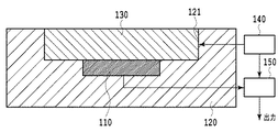
図1は、本発明の第1の実施形態にかかる赤外線センサ100の構成例を示す断面模式図である。赤外線センサ100は、赤外線センサ素子110と、開口部121が形成された樹脂パッケージ120と、赤外線センサ素子110に入射する赤外線の透過率を切り替える光学シャッタ部130と、光学シャッタ130の赤外線透過率を制御する制御部140と、赤外線センサ素子110からの出力をゼロにする補正信号を生成する演算部150とを備える。
[First Embodiment]
FIG. 1 is a schematic cross-sectional view showing a configuration example of an infrared sensor 100 according to the first embodiment of the present invention. The infrared sensor 100 includes an
赤外線センサ110は、入射した赤外線に応じた電気信号を出力する量子型の赤外線センサ素子である。樹脂パッケージ120には、上面に開口部121が形成され、開口部121には、外部と光学的に接続された赤外線センサ素子110が設けられる。
The
光学シャッタ部130は、樹脂パッケージ120の開口部121内に配置され、赤外線センサ素子110と直接的に接合される。光学シャッタ部130は、例えばシャッタが開閉することで、赤外線センサ素子110に入射する赤外線の透過率を切り替えることができる。本実施形態において、光学シャッタ部130は開口部121の全部を覆うように配置されているが、開口部121の一部のみ覆うように配置されていてもよい。光学シャッタ部130が赤外線センサ素子110の視野をすべて覆っていることが好ましい。
The
制御部140は、光学シャッタ部130の赤外線透過率を制御するもので、光学シャッタ部130に接続され、赤外線センサ素子110の出力に基づく制御信号を出力して光学シャッタ部130の赤外線透過率を切り替える。ここで、制御信号に応じて赤外線透過率を切り替えることが可能な光学シャッタとしては、電圧印加により多層膜の相対的位置を変化させて透過率を切り替えることができる干渉フィルタを用いたシャッタが挙げられる。
The
制御部140は、光学シャッタ部130のシャッタを開閉することにより赤外線センサ素子110に対して赤外線が入射している状態と、赤外線センサ素子110に対して赤外線が入射していない状態とを生じさせる。したがって、光学シャッタ部130は、赤外線透過率の低い第1の状態と赤外線透過率の高い第2の状態とに制御可能であることが必要である。光学シャッタ部130は、赤外線透過率の低い第1の状態としての赤外線透過率を10%以下、好ましくは5%以下、より好ましくは1%以下に制御可能なものであることが好ましい。また、赤外線透過率の高い第2の状態として赤外線透過率を90%以上、好ましくは95%以上、より好ましくは99%以上に制御可能なものであることが好ましい。
The
演算部150は、赤外線センサ素子110と制御部140とに接続され、赤外線センサ素子110からの出力信号と制御部140とからの制御信号が入力される。ここで、制御部140が光学シャッタ部130を赤外線透過率を低い状態(上述の第1の状態)に制御している場合、演算部150は赤外線センサ素子110からの出力をゼロにする補正信号を生成する。
The
光学シャッタ部130が、第1の状態に制御されている場合、赤外線センサ素子110に外部から入射される赤外線は実質的に遮断されるため、赤外線センサ素子110に入射される赤外線は光学シャッタ部130の温度に起因する赤外線のみとなる。ここで、赤外線センサ100は、赤外線センサ素子110と光学シャッタ部130とが直接的に接合されているため、赤外線センサ素子110と光学シャッタ部130とが熱的に平衡な状態となる。したがって、赤外線センサ素子110と光学シャッタ部130とに温度差は生じず、赤外線センサ素子110の出力が光学シャッタ部130の影響を受けることがない。
When the
したがって、光学シャッタ部130が、赤外線透過率の低い状態に制御されている場合には、赤外線センサ素子110の出力は原理的にゼロとなる。ただし、赤外線センサ素子110は、視野内の物体からの赤外線以外に、周囲の熱雑音、電磁ノイズ及びICによるオフセット等の様々なノイズに起因した信号をさらに出力するため、赤外線センサ素子110の出力は完全にゼロとなることはない。このとき、演算部150が赤外線センサ素子110の出力をゼロにするような補正信号を生成することにより、様々なノイズに起因した信号をキャンセルすることが可能となる。
Therefore, when the
演算部150が赤外線センサ素子110からの信号を補正することにより、光学シャッタ部130を赤外線透過率が高い状態(上述の第2の状態)に制御している場合においても、赤外線センサ素子110の出力から様々なノイズに起因した信号をキャンセルすることができる。
Even when the
赤外線センサ100は、赤外線センサ素子110と光学シャッタ部130とが熱的に平衡な状態であるため、赤外線センサ素子110の出力が光学シャッタ部130の影響を受けることがない。したがって、光学シャッタ部130からの熱雑音に起因した信号をキャンセルする必要がないため、従来のシャッタ付赤外線センサよりも高精度な赤外線の測定が可能となる。
In the infrared sensor 100, since the
[第2の実施形態]
図2は、本発明の第2の実施形態にかかる赤外線センサ200の構成例を示す断面模式図である。赤外線センサ200は、赤外線センサ素子210と、開口部221が形成された樹脂パッケージ220と、赤外線センサ素子210に接続された金属225と、赤外線センサ素子210に入射する赤外線の透過率を切り替える光学シャッタ部230と、赤外線センサ素子210からの出力をゼロにする補正信号を生成する制御部240とを備える。
[Second Embodiment]
FIG. 2 is a schematic cross-sectional view showing a configuration example of an infrared sensor 200 according to the second embodiment of the present invention. The infrared sensor 200 includes an
赤外線センサ210は、入射した赤外線に応じた電気信号を出力する量子型の赤外線センサ素子である。樹脂パッケージ220には、上面に開口部221が形成され、開口部221は開口部底面に設けられた赤外線センサ素子210と外部とを光学的に接続する。
The
光学シャッタ部230は、樹脂パッケージ220の開口部221内に配置され、赤外線センサ素子210と金属225を介して間接的に接合される。光学シャッタ部230は、赤外線センサ素子210に入射する赤外線の透過率を切り替えることができる。
The optical shutter 230 is disposed in the
金属225は、熱伝導率の高い金属であることが好ましく、具体的には銅、アルミ、ステンレス等が挙げられる。
The
制御部240は、光学シャッタ部230の赤外線透過率を制御するもので、光学シャッタ部230に接続され、制御信号を出力して光学シャッタ部230の赤外線透過率を切り替える。
The
演算部250は、赤外線センサ素子210と制御部240とに接続され、赤外線センサ素子210からの出力信号と制御部240からの制御信号が入力される。ここで、制御部240が光学シャッタ部230を赤外線透過率を低い状態(上述の第1の状態)に制御している場合、演算部250は赤外線センサ素子210からの出力をゼロにする補正信号を生成する。
The
赤外線センサ200は、赤外線センサ素子210と光学シャッタ部230とが金属225を介して間接的に接合されているが、金属225は熱伝導率の高い部材であるため、赤外線センサ素子210と光学シャッタ部230とが熱的に平衡な状態になる。したがって赤外線センサ素子210と光学シャッタ部230とに温度差は生じず、赤外線センサ素子210の出力が光学シャッタ部230の影響を受けることがない。したがって、光学シャッタ部230からの熱雑音に起因した信号をキャンセルする必要がないため、従来のシャッタ付赤外線センサよりも高精度な赤外線の測定が可能となる。
In the infrared sensor 200, the
本発明は、物体検知や温度センサに用いる赤外線センサ装置として好適である。 The present invention is suitable as an infrared sensor device used for object detection and a temperature sensor.
100、200 赤外線センサ装置
110、210 赤外線センサ素子
120、220 構造体
121、221 開口部
130、230 光学シャッタ部
140、240 制御部
225 スペーサ
150、250 演算部
100, 200
Claims (3)
上面に開口部が形成された樹脂パッケージであって、前記開口部には、当該開口部を介して外部と光学的に接続される、前記赤外線センサ素子と外部とを光学的に接続する、樹脂パッケージと、
前記開口部内に配置され、前記赤外線センサ素子と直接的または金属を介して間接的に接合され、赤外線透過率の切り替えが可能な光学シャッタ部と、
前記光学シャッタ部に接続され、制御信号に基づいて前記光学シャッタ部の赤外線透過率を制御する制御部と
を備えることを特徴とする赤外線センサ。 A quantum-type infrared sensor element that outputs a signal corresponding to incident infrared rays;
A resin package having an opening formed on an upper surface thereof, wherein the opening is optically connected to the outside through the opening, and the infrared sensor element and the outside are optically connected. Package and
An optical shutter unit disposed in the opening, directly or indirectly joined to the infrared sensor element via a metal, and capable of switching infrared transmittance;
An infrared sensor comprising: a control unit connected to the optical shutter unit and controlling an infrared transmittance of the optical shutter unit based on a control signal.
Priority Applications (1)
| Application Number | Priority Date | Filing Date | Title |
|---|---|---|---|
| JP2014069347A JP2015190897A (en) | 2014-03-28 | 2014-03-28 | infrared sensor device |
Applications Claiming Priority (1)
| Application Number | Priority Date | Filing Date | Title |
|---|---|---|---|
| JP2014069347A JP2015190897A (en) | 2014-03-28 | 2014-03-28 | infrared sensor device |
Publications (1)
| Publication Number | Publication Date |
|---|---|
| JP2015190897A true JP2015190897A (en) | 2015-11-02 |
Family
ID=54425489
Family Applications (1)
| Application Number | Title | Priority Date | Filing Date |
|---|---|---|---|
| JP2014069347A Pending JP2015190897A (en) | 2014-03-28 | 2014-03-28 | infrared sensor device |
Country Status (1)
| Country | Link |
|---|---|
| JP (1) | JP2015190897A (en) |
Cited By (2)
| Publication number | Priority date | Publication date | Assignee | Title |
|---|---|---|---|---|
| JP2021157742A (en) * | 2020-03-30 | 2021-10-07 | 能美防災株式会社 | Flame detector, and flame detector deterioration degree determination device |
| JP2023084559A (en) * | 2021-12-07 | 2023-06-19 | 株式会社デンソー | virtual image display |
-
2014
- 2014-03-28 JP JP2014069347A patent/JP2015190897A/en active Pending
Cited By (3)
| Publication number | Priority date | Publication date | Assignee | Title |
|---|---|---|---|---|
| JP2021157742A (en) * | 2020-03-30 | 2021-10-07 | 能美防災株式会社 | Flame detector, and flame detector deterioration degree determination device |
| JP7584904B2 (en) | 2020-03-30 | 2024-11-18 | 能美防災株式会社 | Flame detector and flame detector deterioration degree determination device |
| JP2023084559A (en) * | 2021-12-07 | 2023-06-19 | 株式会社デンソー | virtual image display |
Similar Documents
| Publication | Publication Date | Title |
|---|---|---|
| DK2776802T3 (en) | Infrared presence sensor for detection of existence of an object in a monitoring area | |
| US9851258B2 (en) | Thermopile temperature sensor with a reference sensor therein | |
| US10436647B2 (en) | Non-contact temperature measurement sensor | |
| CN102265125B (en) | There is the contactless clinical thermometer of stray radiation shielding | |
| JP5506406B2 (en) | Induction heating cooker | |
| US20160178443A1 (en) | Ambient temperature measurement sensor | |
| JP2013118547A (en) | Infrared camera | |
| WO2009089897A3 (en) | Thermographic camera | |
| US20150379845A1 (en) | Danger Detector With A Non-Contact Heat Radiation Sensor For Detecting An Open Fire As Well As To Determine An Ambient Temperature | |
| EP2738531A1 (en) | Multi-mode temperature measuring device | |
| JP2013531248A (en) | Infrared temperature measurement and stabilization | |
| CN109798987A (en) | Low drifting infrared detector | |
| JP4277927B2 (en) | Induction heating cooker | |
| US20180106681A1 (en) | Infrared sensor for measuring ambient air temperature | |
| TW201732244A (en) | Motion and presence detector | |
| JP2015190897A (en) | infrared sensor device | |
| JP2011095143A (en) | Infrared sensor | |
| JP2006317232A (en) | Infrared sensor | |
| US12306046B2 (en) | Enhanced cooker hood with sensors for remote temperature measurement and presence detection | |
| TWI613427B (en) | Medical thermometer and its use method | |
| KR101164640B1 (en) | Apparatus of thermal infrared camera with identical visibility and visual image | |
| JP2005195435A (en) | Noncontact type temperature detector | |
| JP2010175442A (en) | Thermopile type infrared detector | |
| JP2015226078A (en) | Imaging apparatus | |
| JP2014169968A (en) | Infrared sensor apparatus, and manufacturing method for the same |