JP2015190885A - edge detection device - Google Patents
edge detection device Download PDFInfo
- Publication number
- JP2015190885A JP2015190885A JP2014068980A JP2014068980A JP2015190885A JP 2015190885 A JP2015190885 A JP 2015190885A JP 2014068980 A JP2014068980 A JP 2014068980A JP 2014068980 A JP2014068980 A JP 2014068980A JP 2015190885 A JP2015190885 A JP 2015190885A
- Authority
- JP
- Japan
- Prior art keywords
- height
- edge detection
- edge
- light
- workpiece
- Prior art date
- Legal status (The legal status is an assumption and is not a legal conclusion. Google has not performed a legal analysis and makes no representation as to the accuracy of the status listed.)
- Granted
Links
- 238000003708 edge detection Methods 0.000 title claims abstract description 184
- 238000001514 detection method Methods 0.000 claims abstract description 123
- 230000003287 optical effect Effects 0.000 claims abstract description 49
- 230000008859 change Effects 0.000 claims description 11
- 238000003384 imaging method Methods 0.000 claims description 5
- 238000005286 illumination Methods 0.000 abstract 2
- 238000010586 diagram Methods 0.000 description 29
- 238000012545 processing Methods 0.000 description 27
- 238000000034 method Methods 0.000 description 16
- 238000004364 calculation method Methods 0.000 description 13
- 238000003754 machining Methods 0.000 description 13
- 238000005259 measurement Methods 0.000 description 10
- 238000012935 Averaging Methods 0.000 description 9
- 230000014509 gene expression Effects 0.000 description 9
- 238000009826 distribution Methods 0.000 description 7
- 238000006073 displacement reaction Methods 0.000 description 6
- 230000000694 effects Effects 0.000 description 4
- 230000008569 process Effects 0.000 description 4
- 230000004044 response Effects 0.000 description 4
- 238000005520 cutting process Methods 0.000 description 2
- 230000001678 irradiating effect Effects 0.000 description 2
- 239000000463 material Substances 0.000 description 2
- RYGMFSIKBFXOCR-UHFFFAOYSA-N Copper Chemical compound [Cu] RYGMFSIKBFXOCR-UHFFFAOYSA-N 0.000 description 1
- 238000013459 approach Methods 0.000 description 1
- 230000008901 benefit Effects 0.000 description 1
- 238000004891 communication Methods 0.000 description 1
- 239000010949 copper Substances 0.000 description 1
- 229910052802 copper Inorganic materials 0.000 description 1
- 230000000593 degrading effect Effects 0.000 description 1
- 239000002184 metal Substances 0.000 description 1
- 229910052751 metal Inorganic materials 0.000 description 1
- 230000009467 reduction Effects 0.000 description 1
- 239000004065 semiconductor Substances 0.000 description 1
- 238000004904 shortening Methods 0.000 description 1
- 239000010935 stainless steel Substances 0.000 description 1
- 229910001220 stainless steel Inorganic materials 0.000 description 1
Images


Abstract
Description
本発明は、放電加工機や切削加工機等の工作機械に搭載され、被加工物のエッジを検出する装置に関する。 The present invention relates to an apparatus that is mounted on a machine tool such as an electric discharge machine or a cutting machine and detects an edge of a workpiece.
一般にワイヤ放電加工機などで高精度な加工を行う前には、加工機の走査軸に対して被加工物(ワーク)の基準面を高精度に位置合わせする段取り工程が行われる。段取り工程では、例えば、ワークを加工機の走査軸上の取付け治具に固定し、位置合わせのためのワークの基準面(例えばワークの側面)にダイヤルゲージを押し当て、位置合わせのための基準面に対応する走査軸を動かしてもダイヤルゲージの値が変化しないように、ワークの位置を手動で調整する。しかし、手動での段取り工程では、時間がかかり、また、作業者の技量によって位置合わせ結果にばらつきが生じるという課題があった。 In general, before performing high-accuracy machining with a wire electric discharge machine or the like, a setup process is performed in which a reference surface of a workpiece (workpiece) is aligned with high accuracy with respect to a scanning axis of the machining machine. In the setup process, for example, the workpiece is fixed to a mounting jig on the scanning axis of the processing machine, a dial gauge is pressed against the reference surface (for example, the side surface of the workpiece) for alignment, and the reference for alignment The position of the workpiece is manually adjusted so that the dial gauge value does not change even if the scanning axis corresponding to the surface is moved. However, the manual setup process takes time, and there is a problem that the alignment result varies depending on the skill of the operator.
そこで、作業時間の短縮や、作業者によるばらつきを低減するため、加工機上に機上計測用センサを取付け、自動で段取りを行う方法がある。一般に機上計測用センサとして、接触式センサの他に非接触計測可能な光学式センサがある。光学式センサは、ワーク上面からレーザ光を照射し、反射光を検出して非接触にエッジ位置を計測する。そのため、細い基準穴や柔らかいワークも計測することができる利点がある。しかし、例えば、ワークのエッジは面取りされていることがある。面取りされたエッジの位置を計測する場合、位置によってワーク表面の高さが変化するため、センサに焦点調整機能が無いと、集光スポットが大きくなり、高精度計測ができなかった。 Therefore, there is a method in which an on-machine measurement sensor is mounted on the processing machine and the setup is automatically performed in order to shorten the work time and reduce the variation by the worker. In general, as an on-machine measurement sensor, there is an optical sensor capable of non-contact measurement in addition to a contact sensor. The optical sensor irradiates laser light from the upper surface of the workpiece, detects reflected light, and measures the edge position in a non-contact manner. Therefore, there is an advantage that a thin reference hole and a soft workpiece can be measured. However, for example, the edge of the workpiece may be chamfered. When measuring the position of the chamfered edge, the height of the workpiece surface changes depending on the position. Therefore, if the sensor does not have a focus adjustment function, the focused spot becomes large and high-precision measurement cannot be performed.
面取りされたワークでも高精度にエッジ位置を計測する手法として、例えば、特許文献1に示される手法が提案されている。特許文献1は、三角測量の原理とアクチュエータを用いて、常にオートフォーカスを行い、高精度にエッジ位置を計測している。レーザ光をワーク表面に対して斜めに照射し、反射光を光位置検出センサに集光して、三角測量の原理を用いてワーク表面の高さ検出を行う。さらに、ワーク表面の高さ情報を用いて、対物レンズに接続されたアクチュエータを駆動し、常にフォーカス状態となるようオートフォーカスを行う。そして、高さ検出の基準面からの高さの差があるしきい値ΔZ以上となった位置をエッジ位置とする。オートフォーカスを行いながらエッジ検出するため、面取りされたエッジであっても高精度にエッジを検出することができる。 As a technique for measuring the edge position with high accuracy even for a chamfered workpiece, for example, a technique disclosed in Patent Document 1 has been proposed. Patent Document 1 always performs autofocus using the principle of triangulation and an actuator, and measures the edge position with high accuracy. The laser beam is irradiated obliquely to the workpiece surface, the reflected light is condensed on the optical position detection sensor, and the workpiece surface height is detected using the principle of triangulation. Furthermore, using the height information on the workpiece surface, the actuator connected to the objective lens is driven to perform autofocus so that the focus state is always maintained. A position where the height difference from the reference plane for height detection is equal to or greater than a certain threshold value ΔZ is defined as an edge position. Since edge detection is performed while performing autofocusing, even a chamfered edge can be detected with high accuracy.
特許文献1で開示されている構成では、レーザ光をワーク表面に対して斜めに照射しているため、ワーク表面の高さが変化すると計測位置が水平方向にずれてしまう。そのため、常にフォーカス調整を行って、ワーク表面とレンズとの相対的な位置関係を維持する必要があり、アクチュエータを用いてレンズを駆動し続けなければならなかった。アクチュエータなどの駆動部品を搭載するために、特許文献1で開示されている構成には、エッジ検出装置が大型でコストが高くなるという課題があった。 In the configuration disclosed in Patent Document 1, since the laser beam is irradiated obliquely with respect to the workpiece surface, the measurement position is shifted in the horizontal direction when the height of the workpiece surface changes. Therefore, it is necessary to always perform focus adjustment to maintain the relative positional relationship between the workpiece surface and the lens, and the lens must be continuously driven using an actuator. In order to mount a driving component such as an actuator, the configuration disclosed in Patent Document 1 has a problem that the edge detection device is large and expensive.
本発明は、上記のような課題を解決するためになされたものであり、面取りされたエッジを有するような表面の高さが変化するワークに対しても、小型、低コストで高精度にエッジを検出できるエッジ検出装置を提供することを目的とする。 The present invention has been made in order to solve the above-described problems, and is small, low-cost, and highly accurate even for a workpiece having a chamfered edge and whose surface height varies. An object of the present invention is to provide an edge detection device capable of detecting the above.
本発明におけるエッジ検出装置は、集光された照射光を被検出物の上面に鉛直方向から投光する投光部と、上面で照射光が拡散反射された拡散反射光のうち鉛直方向に対して斜め方向に光軸を有する第1の反射光成分に基づいて上面に対する投光部の相対的な高さを検出する高さ検出部と、高さ検出部の検出結果に基づいて相対的な高さを所定の範囲内に調整するとともに、投光部の被検出物に対する鉛直方向から見た場合の相対位置を所定の経路で移動させる駆動部と、複数の相対位置で拡散反射光のうち第1の反射光成分の光軸とは異なる光軸を有する第2の反射光成分を受光して受光量の変化に基づいて被検出物のエッジを検出するエッジ検出部とを備えるものである。 The edge detection device according to the present invention has a light projecting unit that projects the condensed irradiation light on the upper surface of the object to be detected from the vertical direction, and the vertical direction of the diffuse reflection light in which the irradiation light is diffusely reflected on the upper surface. A height detection unit that detects the relative height of the light projecting unit with respect to the upper surface based on a first reflected light component having an optical axis in an oblique direction, and a relative value based on the detection result of the height detection unit While adjusting the height within a predetermined range and moving the relative position when viewed from the vertical direction with respect to the object to be detected of the light projecting unit, and a diffused reflected light at a plurality of relative positions An edge detector that receives a second reflected light component having an optical axis different from the optical axis of the first reflected light component and detects an edge of the detected object based on a change in the amount of received light. .
本発明におけるエッジ検出装置によれば、投光部が、集光された照射光を被検出物の上面に鉛直方向から投光し、高さ検出部が、上面で照射光が拡散反射された拡散反射光のうち鉛直方向に対して斜め方向に光軸を有する第1の反射光成分に基づいて上面に対する投光部の相対的な高さを検出し、駆動部が、高さ検出部の検出結果に基づいて相対的な高さを所定の範囲内に調整するとともに、投光部の被検出物に対する鉛直方向から見た場合の相対位置を所定の経路で移動させ、エッジ検出部が、複数の相対位置で拡散反射光のうち第1の反射光成分の光軸とは異なる光軸を有する第2の反射光成分を受光して受光量の変化に基づいて被検出物のエッジを検出するので、面取りされたエッジを有するような表面の高さが変化するワークに対しても、小型、低コストで高精度にエッジを検出できる。 According to the edge detection device of the present invention, the light projecting unit projects the condensed irradiation light onto the upper surface of the detection object from the vertical direction, and the height detection unit diffuses and reflects the irradiation light on the upper surface. Based on the first reflected light component having the optical axis in the oblique direction with respect to the vertical direction in the diffuse reflected light, the relative height of the light projecting unit with respect to the upper surface is detected. Based on the detection result, the relative height is adjusted within a predetermined range, and the relative position when viewed from the vertical direction with respect to the object to be detected of the light projecting unit is moved along a predetermined path. The second reflected light component having an optical axis different from the optical axis of the first reflected light component among the diffuse reflected light is received at a plurality of relative positions, and the edge of the detected object is detected based on the change in the amount of received light. Therefore, for workpieces with varying surface height such as chamfered edges Also, small, it detects edges with high accuracy at low cost.
実施の形態1.
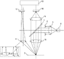
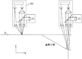
図1は、本発明の実施の形態1によるエッジ検出装置を搭載した加工機の斜視図である。エッジ検出装置は、エッジ検出センサ101と駆動部とを備える。エッジ検出センサ101は、加工機の加工ヘッド1の側面に取り付けられる。エッジ検出センサ101は、単にセンサと呼ばれることもある。被加工物であり、エッジ検出の被検出物であるワーク2は加工機の走査部3(ステージ)に取付け治具14で固定される。エッジ検出センサ101は、ワーク2の上面に光を照射し、ワーク2からの反射光の有無を検出してエッジ検出を行う。
Embodiment 1 FIG.
FIG. 1 is a perspective view of a processing machine equipped with an edge detection device according to Embodiment 1 of the present invention. The edge detection apparatus includes an
なお、本実施の形態において、加工機は、図1に示した3方向(X方向、Y方向、Z方向)を走査軸として動作する。本実施の形態の加工機では、走査部3は、走査部3の上面に平行な(すなわち水平な)互いに直交する2方向(X方向、Y方向)を走査軸として移動し、加工ヘッド1は、走査部3の上面に垂直な(すなわち鉛直な)方向(Z方向)を走査軸として移動するものとする。ただし、必ずしもこれに限定されるものではなく、例えば、走査部3が、3方向(X方向、Y方向、Z方向)を走査軸として移動しても良い。なお、以降の記載において、特に断りがなければ、X方向、Y方向、Z方向は、図1に示す3方向を指す。 In the present embodiment, the processing machine operates using the three directions (X direction, Y direction, and Z direction) shown in FIG. 1 as scanning axes. In the processing machine according to the present embodiment, the scanning unit 3 moves using two directions (X direction and Y direction) that are parallel (that is, horizontal) and orthogonal to the upper surface of the scanning unit 3 as scanning axes, and the processing head 1 is Suppose that the direction of movement perpendicular to the upper surface of the scanning unit 3 (that is, the vertical direction) (Z direction) is used as the scanning axis. However, the present invention is not necessarily limited to this. For example, the scanning unit 3 may move in three directions (X direction, Y direction, and Z direction) as scanning axes. In the following description, the X direction, the Y direction, and the Z direction refer to the three directions shown in FIG. 1 unless otherwise specified.
本実施の形態において、エッジ検出装置は加工機に組み込まれており、加工ヘッド1と走査部3とがエッジ検出装置の駆動部としても機能する。エッジ検出装置の駆動部は、エッジ検出センサ101と被検出物であるワーク2の相対位置を移動させる機能を有する。エッジ検出装置の駆動部は、図示していない制御部に制御されて動作するが、駆動部の動作を制御する機能は駆動部の一部として考えることができる。
In the present embodiment, the edge detection device is incorporated in a processing machine, and the processing head 1 and the scanning unit 3 also function as a drive unit of the edge detection device. The drive unit of the edge detection device has a function of moving the relative position between the
図2は、エッジ検出センサ101の構成を示す図であり、エッジ検出センサ101の構成を側面(図1におけるY方向)から見た構成図となる。また、図2において、実線の矢印は光の進行を表しており、一点鎖線は光軸を表している。これは、以降の構成図においても同様である。光源4は、レーザやLEDなどで構成され、例えば半導体レーザが用いられる。投光レンズ5は、光源4から出射した光を平行光とするよう構成されている。光源4と投光レンズ5の距離は、投光レンズ5のレンズ曲面形状に合わせて最適に設定される。言い換えると、光源4と投光レンズ5の距離は、投光レンズ5の焦点距離等のパラメータを考慮して最適に設定される。投光レンズ5を通って平行光となった光を投光絞り6で適切な大きさに絞る。投光絞り6によってワーク2上に照射される光の集光スポット径を決定することができる。
FIG. 2 is a diagram illustrating the configuration of the
次に、ビームスプリッタ7は、投光レンズ5を通って平行光となり、投光絞り6で絞られた光をワーク2の方向に折り返す機能を有し、プレート型やキューブ型がある。対物レンズ8は、ビームスプリッタ7で折り返された平行光を集光するよう構成されており、ワーク2の表面(ワーク表面)が集光位置にくるよう調整される。対物レンズ8は、ワーク表面への照射光の光軸がワーク表面に対して垂直な方向となるように配置される。したがって、ワーク表面には、ワーク表面に対して垂直な方向から光が照射される。ここで、光軸とは、照射される光束全体、又は受光される光束全体の代表となる仮想的な光線であり、光束全体としての進行方向を表す軸となる。
Next, the beam splitter 7 has a function of turning parallel light through the light projection lens 5 and turning back the light focused by the light projection aperture 6 in the direction of the
光源4、投光レンズ5、投光絞り6、ビームスプリッタ7、対物レンズ8によって、投光部が構成される。投光部は、集光された照射光をワーク2の表面に照射(投光)する機能を有する。なお、ワーク2の表面又はワーク表面とは、特に断りがない限りワーク2の上面を指す。また、通常はワーク表面が水平となるようにワーク2が配置され、この場合には表面に対して垂直な方向は鉛直方向となる。対物レンズ8を通ってワーク表面に照射された光は、ワーク表面で拡散反射する。一般的に、後述のように加工前のワーク表面は粗面となっており、照射された光は拡散反射する。
The light source 4, the projection lens 5, the projection diaphragm 6, the beam splitter 7, and the
ワーク表面で拡散反射した光のうち、垂直方向付近に反射した成分、すなわち垂直方向に光軸を有する成分は、対物レンズ8を再度通って平行光となる。ビームスプリッタ7は、ワーク2から反射し、対物レンズ8から取込まれた光については透過する。受光レンズ9は、ワーク2から反射し、対物レンズ8から取込まれ、ビームスプリッタ7を透過した光をエッジ検出用受光素子10上に集光するよう構成されている。受光レンズ9とエッジ検出用受光素子10との距離は、受光レンズ9のレンズ曲面形状に合わせて最適に設定される。
Of the light diffusely reflected on the workpiece surface, the component reflected in the vicinity of the vertical direction, that is, the component having the optical axis in the vertical direction passes through the
エッジ検出用受光素子10には、例えばフォトダイオードなどが用いられ、ワーク表面で反射した光の強度を電気信号に変換する機能を有する。変換された電気信号は、信号演算部13に送られる。対物レンズ8、受光レンズ9、エッジ検出用受光素子10、信号演算部13によって、エッジ検出部が構成される。エッジ検出部は、ワーク2の表面で拡散反射された拡散反射光のうち、垂直方向付近に反射した成分、すなわちワーク表面に対して垂直方向に光軸を有する成分を受光して、受光量の変化に基づいてエッジの位置を検出する機能を有する。
For example, a photodiode is used as the edge detection light-receiving
また、高さ検出用レンズ11は、ワーク2の表面に照射され、ワーク2の表面で拡散反射した光のうち、鉛直方向に対して斜め方向に拡散反射した成分、すなわち斜め方向に光軸を有する成分を取込み、高さ検出用受光素子12上に集光するよう構成される。ここで、拡散反射した光のうち、鉛直方向に対して斜め方向に光軸を有し、高さ検出用レンズ11に取り込まれる成分が、第1の反射光成分となる。また、ワーク2の表面で拡散反射した光のうち、ワーク表面に対して垂直方向(鉛直方向)に光軸を有する成分は、第2の反射光成分となる。高さ検出用レンズ11、高さ検出用受光素子12、信号演算部13によって、高さ検出部が構成される。高さ検出部は、第1の反射光成分を受光して、受光した光の入射方向(光軸の向き)に基づいてワーク表面の相対的な高さを検出する機能を有する。
In addition, the
高さ検出用レンズ11は、例えば、図2の左下の破線で囲った領域に示すように、レンズと三角プリズムの組合せや、曲面の中心で2分割されたレンズ等が用いられ、斜めに入射した光を高さ検出用受光素子上に集光できる構成であれば良い。今後は説明上、簡単のため、単一のレンズ形状として記す。高さ検出用受光素子12は、三角測量の原理により、ワーク表面の高さが変わった場合に、反射光が集光される高さ検出用受光素子12上の位置が変化したことを検出する素子であり、例えば、光位置検出素子PSD(Position Sensitive Detector)やリニアイメージャや2次元イメージャが用いられる。高さ検出用受光素子12で検出された電気信号は信号演算部13に送られる。高さ検出用レンズ11の光軸とエッジ検出用の受光レンズ9の光軸とは、ずらして配置している。
For example, as shown in the area surrounded by the broken line at the lower left in FIG. 2, the
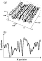
ここで、加工に用いられるワーク2について説明を行う。ワーク2には、超硬材やステンレス、銅などの金属ワークが一般的に用いられる。加工前のワーク2の表面は、切り出した際に付いた切削加工痕などによって微小な凹凸形状をしている。すなわち、加工前のワーク2の表面は粗面となっている。図3は、加工前のワーク2の表面を三次元測定機で測定した結果の一例を表す図であり、超硬材のワーク表面を測定した結果の一例である。図3(a)は、ワーク表面の凹凸形状の2Dマップ(2次元マップ)である。また、図3(b)は、あるY方向位置におけるX−Z平面でのワーク表面の断面形状を示している。ワーク表面には2〜3μmの微小な凹凸があり、粗面となっている。
Here, the workpiece |
そのため、ワーク表面に集光したビームを照射した場合、反射角度に対する反射光の強度分布がワーク2上の位置によって変化する。したがって、受光素子で受光する反射光の強度がワーク2上の位置によって大きく変化し、安定した検出信号(受光素子の出力)が得られず、ばらつきが生じる。そこで、投光絞り6における投光ビームの絞りは、ワーク表面に照射される集光スポット径が凹凸を複数個含むように設定することが望ましい。理想的には、ワーク表面に照射される集光スポット径が小さい方が、エッジの検出精度は向上する。しかし、ワーク表面が微小な凹凸形状である場合には、集光スポット径を小さくし過ぎると、凹凸の影響を受けて反射光の反射角度に対する強度分布が照射位置によって変化しやすくなり、検出信号のばらつきが大きくなる。そのため、集光スポット径は、検出信号のばらつきを抑えつつ、検出の精度が高い適切な大きさと必要がある。集光スポット径は使用目的などに応じて決定することになる。
Therefore, when the focused beam is irradiated on the workpiece surface, the intensity distribution of the reflected light with respect to the reflection angle changes depending on the position on the
ここで、集光スポットのエアリーディスクの直径Dは回折計算により、式(1)で与えられる。式(1)において、λは光の波長、f1は対物レンズの焦点距離、dは投光絞り6の開口径である。例えば、集光スポットのエアリーディスクが凹凸を3つ程度含むように、スポット径Dが8μmとすると、波長λ=660nm、対物レンズの焦点距離f1=18mmのとき、投光絞り6の開口径d=3.6mmとなる。ここで、投光絞り6の開口径でスポット径を決定したが、投光絞り6を用いずに投光レンズ5のレンズ径でスポット径を決定しても良い。 Here, the diameter D of the airy disk of the focused spot is given by equation (1) by diffraction calculation. In equation (1), λ is the wavelength of light, f1 is the focal length of the objective lens, and d is the aperture diameter of the projection aperture 6. For example, assuming that the spot diameter D is 8 μm so that the airy disk of the condensing spot includes about 3 irregularities, the aperture diameter d of the projection aperture 6 is obtained when the wavelength λ = 660 nm and the focal length f1 of the objective lens = 18 mm. = 3.6 mm. Here, the spot diameter is determined based on the opening diameter of the projection aperture 6, but the spot diameter may be determined based on the lens diameter of the projection lens 5 without using the projection aperture 6.
![]()
![]()
また、投光絞り径dと集光スポット径Dが決定すると、照射光の集光スポットの焦点深度ΔZを計算することができる。以降の記載において、特に説明なく単に焦点深度と記載した場合には、ワーク表面への照射光の集光スポットの焦点深度を指す。例えば、上記の条件の場合、集光時のスポット径の1.5倍となるデフォーカス量を焦点深度ΔZとすると、焦点深度ΔZは120μmであった。この焦点深度内にワーク表面の高さを調整できれば、エッジ検出を行う上で問題ない程度にしかスポット径が変化しないため、精度を悪化させずにエッジを検出することができる。ここで、焦点深度ΔZを集光時のスポット径の1.5倍となるデフォーカス量としたが、実際にはエッジ検出時の精度が悪化しない範囲であれば良い。ここで、エッジ検出とは、エッジの有無に加えてエッジの位置を検出(計測)することであり、エッジ検出時の精度とは、検出(計測)したエッジの位置の精度である。 When the projection aperture diameter d and the condensing spot diameter D are determined, the focal depth ΔZ of the condensing spot of the irradiation light can be calculated. In the following description, when it is simply described as the depth of focus without any particular explanation, it indicates the depth of focus of the condensed spot of the irradiation light on the work surface. For example, in the case of the above conditions, when the defocus amount that is 1.5 times the spot diameter at the time of condensing is the depth of focus ΔZ, the depth of focus ΔZ is 120 μm. If the height of the workpiece surface can be adjusted within this depth of focus, the spot diameter changes only to the extent that there is no problem in performing edge detection, so that the edge can be detected without degrading accuracy. Here, the depth of focus ΔZ is a defocus amount that is 1.5 times the spot diameter at the time of condensing, but it may be in a range that does not actually deteriorate the accuracy at the time of edge detection. Here, the edge detection is to detect (measure) the position of the edge in addition to the presence or absence of the edge, and the accuracy at the time of edge detection is the accuracy of the position of the detected (measured) edge.
次に、高さ検出用レンズ11と高さ検出用受光素子12を用いた、ワーク表面の高さ検出方法について説明する。図4は、本実施の形態のエッジ検出装置における高さ検出方法を説明するための図であり、エッジ検出センサ101を側面から見た図となる。図4(a)は、ワーク2の表面が対物レンズ8の焦点位置にある場合である。高さ検出レンズ11は、例えば、凸レンズと三角プリズムで構成されるが、ここでは1つのレンズ形状として示している。高さ検出レンズ11の主点から高さ検出用受光素子12の受光面までの距離をa、ワーク表面までの距離をbとする。また、高さ検出レンズ11の光軸から高さ検出用受光素子12の中心までの距離をc、対物レンズ8の光軸までの距離をdとする。このとき、ワーク表面で散乱された光のうち斜め方向に拡散反射した成分が、高さ検出用レンズ11によって高さ検出用受光素子12の中心に集光され、式(2)及び式(3)の関係を満たしている。ここで、f2は高さ検出レンズ11の焦点距離である。
Next, a method for detecting the height of the workpiece surface using the

![]()
![]()
一方、図4(b)は、ワーク2の表面が、図1の−Z方向に距離Lだけ変化した場合である。ワーク表面の高さが焦点位置から遠ざかる。そのため、高さ検出用レンズ11への反射光成分の入射角が変化し、高さ検出用レンズ11へ入射する反射光成分の光軸の向きが変化するため、高さ検出用レンズで集光される高さ検出用受光素子12上の位置が+X方向に距離ΔHだけ変化する。このとき、式(4)の関係が満たされる。ここで、デフォーカス時(ワーク2の表面の高さが変化した場合)の高さ検出用の反射光の光軸と焦点面(焦点位置にある面)との交点をAとし、ワーク2の表面に投光される光の光軸と焦点面との交点をBとすると、d’は交点Aと交点Bとの位置の差異を表す。
On the other hand, FIG. 4B shows a case where the surface of the
![]()
![]()
d’は式(5)の関係を満たすため、式(3)、式(4)、式(5)から、ΔHは、式(6)で表される。例えば、a=75mm、b=40mm、d=21mmとすると、L=1mm変化した場合、ΔH≒1mmとなり、高さ検出用受光素子12上の集光位置の変位量を、ワーク表面の高さ変位量と同等にすることができる。
Since d ′ satisfies the relationship of Expression (5), ΔH is expressed by Expression (6) from Expression (3), Expression (4), and Expression (5). For example, if a = 75 mm, b = 40 mm, and d = 21 mm, when L = 1 mm, ΔH≈1 mm, and the amount of displacement of the condensing position on the height detecting
![]()
![]()
また、図4(c)は、ワーク2の表面が+Z方向に距離Lだけ変化した場合である。ワーク表面の高さが焦点位置からセンサ側に近づく。そのため、高さ検出用レンズ11への入射角が変化するため、上記と同様の考え方により、高さ検出用レンズ11で集光される高さ検出用受光素子12上の集光位置が−X方向に距離ΔH変化する。このように、センサに対するワーク表面の位置(高さ)が変化すると、高さ検出用受光素子12上のスポットの集光位置が変化する。上記のように高さ検出用受光素子上のスポット位置(集光位置)がΔH変化した場合、式(6)より、ワーク表面の高さ変位量Lを式(7)のように求めることができる。
FIG. 4C shows a case where the surface of the
したがって、高さ検出用受光素子12上のスポット位置を計測することで、ワーク表面の高さを算出することができる。そして、ワーク表面の高さと対物レンズの焦点位置との変位Lが、照射光の集光スポットの焦点深度ΔZに対して0≦L≦ΔZ/2であれば、高精度にエッジを計測可能である。すなわち、ワーク表面の高さと対物レンズの焦点位置との変位Lが、対物レンズ8の焦点位置を中心とした焦点深度の範囲内であれば、高精度にエッジを計測可能である。しかし、ワーク表面の高さと対物レンズの焦点位置との変位Lが、焦点深度外(L>ΔZ/2)となると、加工ヘッドのZ方向位置を、例えばL変化させて、ワーク表面の高さが焦点深度内に入るよう調整する。このように、ワーク表面の高さが焦点深度外となった場合には、加工ヘッドのZ方向高さを動かして、センサ高さを調整すれば、常に焦点深度内にワーク表面高さを調整することができる。
Therefore, the height of the workpiece surface can be calculated by measuring the spot position on the height detecting
次に、エッジ検出方法について説明を行う。図5は、本実施の形態のエッジ検出装置における直角なエッジの検出方法について説明するための図である。図5は、走査部3のX方向の各走査位置におけるエッジ検出センサ101とワーク2の相対位置を側面から見たイメージ図と、走査位置とエッジ検出用受光素子10の出力との関係を示す図とから構成されている。ワーク2の上方にエッジ検出センサ101を設置する。エッジ検出センサ101がワーク2のエッジ(X=X2)を横切るように、走査部3をX方向に距離ΔX動かして、エッジ検出用受光素子10で信号を取得する。位置X1ではエッジ検出センサ101はワーク2の上にあり、ワーク2上に照射光が集光され、反射光が得られるため、エッジ検出用受光素子から出力V1が得られる。
Next, an edge detection method will be described. FIG. 5 is a diagram for explaining a method for detecting a right-angled edge in the edge detection apparatus according to the present embodiment. FIG. 5 is an image view of the relative positions of the
次に、走査部3が移動することで、エッジ検出センサ101がワーク2のエッジ上(位置X2)に移動した場合には、集光スポットの一部がワーク2の外に出るため、ワーク2の上にエッジ検出センサ101がある場合よりも、エッジ検出用受光素子10から得られる出力が低下する。このときの出力をV2=α*V1(0<α<1)とする。最後に、エッジ検出センサ101がワーク2の外に移動した場合、ワーク2の表面からの反射光がほとんど得られなくなるため、エッジ検出用受光素子10からの出力はほとんど得られなくなる。ここで、走査部3の上面は、光を反射しないような構成とすることができる。また、走査部3の上面が、焦点深度の範囲から十分に外れていれば、光は集光されないので、エッジ検出用受光素子10では反射光をほとんど受光しない。このように、エッジ検出用受光素子10の出力がV2となった位置をエッジ位置として計測することができる。例えば、α=0.5である。
Next, when the scanning unit 3 moves and the
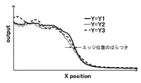
しかし、実際に加工に用いられるワーク2のエッジは、数μmの微小な凹凸形状によって揺らいでいる。図6は、本実施の形態のエッジ検出装置においてワーク2のY方向の異なる位置Y1、Y2、Y3でエッジを検出した結果の一例を示す図である。図6において、横軸はX方向の位置を表し、縦軸はエッジ検出用受光素子10の出力の大きさを表す。Y方向の位置が異なると、エッジ部の凹凸の影響により検出するエッジ位置にばらつきが生じる。そのため、次のような平均化の手法を用いてエッジ検出のばらつきを低減することができる。
However, the edge of the
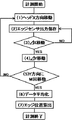
図7は、本実施の形態のエッジ検出装置におけるエッジ検出時の平均化アルゴリズム(平均化手法)のフローチャートである。また、図8は、本実施の形態のエッジ検出装置におけるエッジ検出時の平均化アルゴリズムを説明するための図である。図8は、ワーク2を上面から見た場合の検出経路の一例を示している。図7、図8を用いて、平均化アルゴリズムを説明する。まず、エッジ検出を開始後、エッジ検出センサ101がエッジを横切るようにX方向に距離ΔX移動する。例えば、ΔX=50μmである。その際、X方向位置に対するエッジ検出用受光素子10の信号を取得し、信号演算部13に保存する。X方向に距離ΔX移動し終わると、Y方向に距離ΔY移動する。例えば、ΔY=10μmである。Y方向に移動が終わると、もう一度、エッジ検出センサ101がエッジを横切るように−X方向に距離ΔX移動し、その後、Y方向に距離ΔY移動する。このように、図8に示すようにジグザグの経路で移動し、Y方向に距離ΔYずつM回移動し終わると計測を終了する。例えば、M=40である。
FIG. 7 is a flowchart of an averaging algorithm (average method) at the time of edge detection in the edge detection apparatus of the present embodiment. FIG. 8 is a diagram for explaining an averaging algorithm at the time of edge detection in the edge detection apparatus of the present embodiment. FIG. 8 shows an example of a detection path when the
図9は、本実施の形態のエッジ検出装置におけるエッジ演算方法の一例を説明する図である。図9(a)は、M回のエッジ検出のそれぞれで得られたエッジ検出用受光素子10からの出力信号を表す。また、図9(b)は、エッジ検出用受光素子10からのM個の出力信号を平均化した信号を表す。図9のようにM回検出(計測)したX方向位置に対するエッジ検出用受光素子10からの出力信号のデータを平均化し、最大値V1に対してV2=α*V1となるX方向位置を信号演算部で算出することで、高精度にエッジ位置を検出(計測)することができる。このように、エッジを複数回検出した結果を平均化することで、微小な凹凸によるエッジ位置のばらつきの影響を低減し、高精度にエッジ位置を検出することができる。ここで、平均化のためのジグザグ経路は一例であり、Y方向に異なる位置を複数回検出し、得られた信号出力を平均化してエッジ位置を検出すれば良い。また、測定点数M=1でも良く、ばらつきが少なければ、1つの信号からエッジを検出しても良い。
FIG. 9 is a diagram for explaining an example of an edge calculation method in the edge detection apparatus according to the present embodiment. FIG. 9A shows an output signal from the edge detection light-receiving
以上のように、直角なエッジであれば、ワーク2の上面で焦点調整を実施しておけば、エッジ位置までワーク2の上面が焦点深度内に入っているため、照射光を集光した集光スポットで高精度にエッジを計測することができる。しかし、エッジが面取りされている場合には、別の課題が発生する。図10は、面取りされたエッジ(面取りエッジ)を検出する場合の課題を説明する図である。図10は、走査部3のX方向の各走査位置におけるエッジ検出センサ101とワーク2の相対位置を側面から見たイメージ図である。面取りされたエッジでは、ワーク2の上面で焦点調整をしていても、エッジを検出する際にX方向にワーク2が移動すると、面取り部(面取りされた部分)でワーク2の表面の高さが変化して焦点深度外となることがある。そのため、集光されたスポットと比較して大きなスポット径でエッジ検出することとなり、エッジ位置の検出精度が低下してしまう。これを解決するため、エッジ検出時の高さ検出部を用いた高さ調整方法について説明する。
As described above, if the edge is a right angle, if the focus adjustment is performed on the upper surface of the
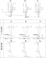
図11は、本実施の形態のエッジ検出装置における面取りエッジでの高さ検出を説明する図である。図11の上段の図は、エッジ検出センサ101とワーク2の相対位置を側面から見たイメージ図である。図11の中段の図は、ワーク2の表面(上面)に照射された光のスポット(投光スポット)の様子を説明する図である。図11の下段の図は、高さ検出部の動作を説明する図である。図11(A)は、エッジ検出センサ101がワーク上面の平坦部の上方に位置しており、ワーク上面の平坦部にて焦点調整を行った状態である。投光スポットはワーク上面に集光されており、高さ検出用レンズ11にて取り込まれた光は、高さ検出用受光素子12のX方向の中心位置に集光される。ここで、平坦部とは、ワーク2の上面の面取りされた部分を除く部分を指し、上面のうちで微小な凸凹を除いて平均的に平坦な領域を指す。
FIG. 11 is a diagram for explaining the height detection at the chamfered edge in the edge detection apparatus of the present embodiment. The upper part of FIG. 11 is an image view of the relative position between the
ここで、投光スポットとは、ワーク2の表面に照射(投光)された光のスポットであり、ワーク2の表面が焦点深度内にある場合と、焦点深度外にある場合との両方を含んでいる。一方、集光スポットとは、ワーク2の表面が対物レンズ8の焦点距離にある場合、または焦点深度内にある場合に、ワーク2の表面に照射された光のスポットを指している。
Here, the light projection spot is a spot of light irradiated (projected) on the surface of the
次に、図11(B)に示すように、X方向位置が面取り領域内に位置し、ワーク表面のZ方向位置がZ1(−ΔZ/2<Z1<0)だけ変化したとする。ワーク2の表面は焦点深度内であるため、投光スポット径はほとんど変化しない。また、高さ検出用受光素子12上のスポット位置は、+X方向に距離ΔH1変化する。信号演算部13では、スポット位置の変化量ΔH1からワークの高さ変化量Z1を計算し、−ΔZ/2<Z1<ΔZ/2であるか判定する。Z1は前記の条件を満たしているため、エッジの検出を続ける。
Next, as shown in FIG. 11B, it is assumed that the position in the X direction is located in the chamfered region, and the position in the Z direction on the workpiece surface is changed by Z1 (−ΔZ / 2 <Z1 <0). Since the surface of the
図11(C)は、ワーク表面の高さがZ2(Z2<−ΔZ/2)だけ変化した場合の図である。高さ検出用受光素子12上のスポット位置は、距離ΔH2(ΔH2>ΔH1)変化する。図11(C)の場合、Z2<−ΔZ/2であるため、信号演算部13は焦点深度外にワーク表面の高さが変化したことを検出する。
FIG. 11C is a diagram when the height of the workpiece surface changes by Z2 (Z2 <−ΔZ / 2). The spot position on the height detecting
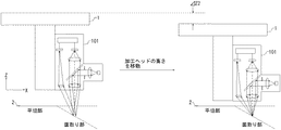
図12は、本実施の形態のエッジ検出装置における焦点調整方法を説明する図である。図12は、エッジ検出センサ101とワーク2の相対位置を側面から見たイメージ図である。図12に示すように、加工ヘッド1のZ方向位置を移動させ、エッジ検出センサ101のZ方向位置を距離ΔZ2だけワーク2に近づける。その結果、ワーク表面の高さが焦点深度内に入り、高さ検出用受光素子12上のスポット位置も中心方向に移動する。このように、高さ検出用レンズ11と高さ検出用受光素子12を用いれば、ワーク表面の高さが焦点深度外に移動したことを検出することができ、加工ヘッド1のZ方向位置を移動させることで、ワーク表面の高さを焦点深度内に調整することができる。本実施の形態のエッジ検出装置は、以上のように動作する。
FIG. 12 is a diagram for explaining a focus adjustment method in the edge detection apparatus according to the present embodiment. FIG. 12 is an image view of the relative position between the
上記のように、本実施の形態のエッジ検出装置では、投光ビーム(照射光)をワーク表面の平坦部に対して垂直に投光(照射)している。すなわち、本実施の形態のエッジ検出装置では、鉛直方向を光軸としてワーク表面に照射光を照射している。したがって、面取り部にてワーク表面の高さが変化しても、水平方向に計測位置がずれることはなく、ワーク表面位置が、照射光の集光スポットの焦点深度内に入っていれば、エッジ計測を継続することができる。ワーク表面位置が焦点深度外になったことを検出すれば、加工ヘッド1のZ方向位置を動かし、エッジ検出センサ101を動かして、ワーク表面位置が焦点深度内に入るよう調整すれば良い。したがって、本実施の形態のエッジ検出装置では、アクチュエータのような駆動部品を必要としない。上述の通り、通常はワーク表面の平坦部が水平となるようにワーク2が配置され、この場合には平坦部に対して垂直な方向は鉛直方向となる。
As described above, in the edge detection apparatus of the present embodiment, the light projection beam (irradiation light) is projected (irradiated) perpendicularly to the flat portion of the workpiece surface. That is, in the edge detection apparatus of the present embodiment, the workpiece surface is irradiated with irradiation light with the vertical direction as the optical axis. Therefore, even if the height of the workpiece surface changes at the chamfered portion, the measurement position does not shift horizontally, and if the workpiece surface position is within the focal depth of the focused spot of the irradiated light, the edge Measurement can be continued. If it is detected that the workpiece surface position is out of the depth of focus, the Z-direction position of the machining head 1 is moved, and the
照射光を斜め方向から照射した場合、ワーク表面の高さが変化すると光が照射される位置が水平方向にずれてしまう。したがって、エッジを検出している位置が水平方向にずれてしまい、検出されたエッジ位置に誤差が発生してしまう。図13は、ワーク表面に斜め方向から光を照射した場合のエッジ検出を説明する図である。図13の中心の図は、ワーク表面の高さが焦点位置にある場合を表し、図13の左右の図は、ワーク表面の高さが焦点位置からずれている場合を表す。ワーク表面の高さが焦点位置からずれている場合には、検出される位置が水平方向にずれてしまう。アクチュエータなどの応答の速い駆動部品を追加して、高精度のオートフォーカスを行うことでこの問題を解決することが考えられるが、装置が大型化し、高価になるという問題が発生する。一方、本実施の形態のエッジ検出装置によれば、このような問題は発生しない。 When the irradiation light is irradiated from an oblique direction, the position where the light is irradiated shifts in the horizontal direction when the height of the workpiece surface changes. Therefore, the position where the edge is detected is shifted in the horizontal direction, and an error occurs in the detected edge position. FIG. 13 is a diagram for explaining edge detection when the work surface is irradiated with light from an oblique direction. The center diagram in FIG. 13 represents the case where the height of the workpiece surface is at the focal position, and the left and right diagrams in FIG. 13 represent the case where the workpiece surface height is deviated from the focal position. When the height of the workpiece surface is deviated from the focal position, the detected position is deviated in the horizontal direction. Although it is conceivable to solve this problem by adding high-response drive parts such as actuators and performing high-precision autofocusing, there arises a problem that the apparatus becomes large and expensive. On the other hand, according to the edge detection apparatus of the present embodiment, such a problem does not occur.
また、本実施の形態のエッジ検出装置は、ワーク2に投光ビーム(照射光)を投光(照射)する投光部と、ワーク2からの反射光を受光してワーク2のエッジを検出するエッジ検出部と、ワーク2からの反射光を受光してワーク2の表面の高さを検出する高さ検出部とを備え、投光部及びエッジ検出部の光軸からずれた位置に、高さ検出部の光軸を設けている。すなわち、対物レンズ8の光軸と高さ検出用レンズ11の光軸とが異なるように構成している。したがって、ワーク表面の高さを検出し、ワーク表面が常に焦点深度内に入るように加工ヘッドの高さを調整すれば、面取り部のようなワーク表面の高さが変化するワークのエッジも高精度に計測できるエッジ検出装置を、アクチュエータのような駆動部品を必要とせずに、小型で安価に得ることができる。
Moreover, the edge detection apparatus of this Embodiment detects the edge of the workpiece |
面取りされたエッジでは、ワーク表面の高さは徐々に変化する。また、上述の通り、本実施の形態のエッジ検出装置においては、ワーク表面が焦点深度内に入るように焦点調整できればよく、高精度(高分解能)の焦点調整を必要としない。したがって、走査部3の移動に伴って、面取りされたエッジに対して高速に(頻繁に)焦点調整を行う必要がなく、加工機に予め備えられる加工ヘッド1又は走査部3の高さ調整機能を用いてエッジ検出センサ101とワーク表面との距離(ワーク表面に対するエッジ検出センサ101の相対的な高さ)を調整することで焦点調整を行って、ワーク2のエッジを検出することが可能となる。
At the chamfered edge, the height of the workpiece surface gradually changes. Further, as described above, in the edge detection device of the present embodiment, it is only necessary to adjust the focus so that the work surface falls within the depth of focus, and high-precision (high resolution) focus adjustment is not required. Therefore, it is not necessary to adjust the chamfered edge at high speed (frequently) with the movement of the scanning unit 3, and the height adjustment function of the processing head 1 or the scanning unit 3 provided in advance in the processing machine. By adjusting the distance between the
この結果、アクチュエータのような駆動部品を新たに設ける必要がなく、小型で安価に構成することが可能となる。なお、上述の通り、ワーク表面が焦点深度内に入るように焦点調整できればよいので、必ずしもエッジ検出センサ101全体の高さを調整する必要はなく、少なくとも投光部の高さを調整できればよい。エッジ検出センサ101全体の高さを調整する場合には、投光部とエッジ検出部で対物レンズ8を共用できるなどエッジ検出センサ101の構成を簡略化でき、投光部と高さ検出部との相対位置が固定となりワーク表面が焦点深度内か否かの判定処理が容易となる等の利点がある。
As a result, it is not necessary to newly provide a drive component such as an actuator, and it is possible to configure a small and inexpensive device. Note that, as described above, it is only necessary to adjust the focus so that the work surface falls within the depth of focus. Therefore, it is not always necessary to adjust the height of the
加工ヘッド1又は走査部3を高さ調整に用いる場合、加工機のコントローラと通信して動かす必要があり、応答時間が長くなる。そのため、従来のエッジ検出装置では、アクチュエータのような駆動部品を取り付けて、走査部によるX−Y平面内の移動速度に対して十分早い応答時間で高さ調整を行っていた。つまり、加工ヘッド1を高速に動かし続けることは現実的に困難であるため、従来のエッジ検出装置では、アクチュエータが必須であった。一方、本実施の形態のエッジ検出装置においては、早い応答時間で焦点調整を行う必要がないので、アクチュエータのような駆動部品を新たに設ける必要がなく、小型で安価に構成することが可能となる。 When the processing head 1 or the scanning unit 3 is used for height adjustment, the processing head 1 or the scanning unit 3 needs to be moved in communication with the controller of the processing machine, which increases the response time. For this reason, in the conventional edge detection device, a driving component such as an actuator is attached, and the height is adjusted with a sufficiently fast response time with respect to the moving speed in the XY plane by the scanning unit. That is, since it is practically difficult to keep the machining head 1 moving at high speed, an actuator is essential in the conventional edge detection device. On the other hand, in the edge detection device of the present embodiment, since it is not necessary to perform focus adjustment with a quick response time, there is no need to newly provide a driving component such as an actuator, and it can be configured in a small and inexpensive manner. Become.
なお、上述の通り、加工前のワーク2の表面は一般的に粗面であるが、鉛直方向(ワーク2の平坦部に対して垂直な方向)から照射される光に対して、反射光の強度分布は鉛直方向が強い場合が多く、エッジ検出部は鉛直方向の反射光を受光できるように構成することが望ましい。また、上述の通り、ワーク2の表面に微小な凹凸形状がある場合には、反射光の反射角度に対する強度分布が照射位置によって変化するが、平均すると鉛直方向で受光するのが最も効率が良い。
Note that, as described above, the surface of the
以上のように、本実施の形態のエッジ検出装置は、投光部が、集光された照射光を被検出物の上面に鉛直方向から投光し、高さ検出部が、上面で照射光が拡散反射された拡散反射光のうち鉛直方向に対して斜め方向に光軸を有する第1の反射光成分に基づいて上面に対する投光部の相対的な高さを検出し、駆動部が、高さ検出部の検出結果に基づいて相対的な高さを所定の範囲内に調整するとともに、投光部の被検出物に対する鉛直方向から見た場合の相対位置を所定の経路で移動させ、エッジ検出部が、複数の相対位置で拡散反射光のうち第1の反射光成分の光軸とは異なる光軸を有する第2の反射光成分を受光して受光量の変化に基づいて被検出物のエッジを検出するので、面取りされたエッジを有するような表面の高さが変化するワークに対しても、小型、低コストで高精度にエッジを検出できる。 As described above, in the edge detection device according to the present embodiment, the light projecting unit projects the condensed irradiation light onto the upper surface of the object to be detected from the vertical direction, and the height detection unit emits the irradiation light on the upper surface. Detects the relative height of the light projecting unit with respect to the upper surface based on the first reflected light component having the optical axis in the oblique direction with respect to the vertical direction among the diffusely reflected light that is diffusely reflected, While adjusting the relative height within a predetermined range based on the detection result of the height detection unit, the relative position when viewed from the vertical direction with respect to the detected object of the light projecting unit is moved along a predetermined path, The edge detection unit receives a second reflected light component having an optical axis different from the optical axis of the first reflected light component among the diffusely reflected light at a plurality of relative positions, and is detected based on a change in the amount of received light Because the edge of an object is detected, the height of the surface with chamfered edges changes. Respect also, small, detects edges with high accuracy at low cost.
実施の形態2.
実施の形態2では、実施の形態1に対して部品点数を削減し、さらにコストダウンや小型化を行った例について説明する。なお、実施の形態1と重複する点については説明を省略する。
In the second embodiment, an example will be described in which the number of parts is reduced as compared with the first embodiment, and the cost is reduced and the size is reduced. Note that the description of the same points as those in Embodiment 1 is omitted.
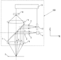
図14は、本発明の実施の形態2によるエッジ検出装置におけるエッジ検出センサ102の構成を示す図であり、エッジ検出センサ102の構成を側面(図1におけるY方向)から見た構成図となる。エッジ検出センサ102以外の構成は、実施の形態1におけるものと同様である。本実施の形態のエッジ検出センサ102では、実施の形態1のエッジ検出センサ101に対して、投光レンズ5と受光レンズ9を削減した。光源4から出た発散光が対物レンズ8によってワーク2の表面に集光される。本実施の形態のエッジ検出センサ102では、投光部の集光位置と、エッジ検出用受光素子10、及び高さ検出用受光素子12の位置が結像関係にある。なお、本実施の形態のエッジ検出センサ102では、光源4、投光絞り6、ビームスプリッタ7、対物レンズ8によって、投光部が構成される。また、本実施の形態のエッジ検出センサ102では、対物レンズ8、エッジ検出用受光素子10、信号演算部13によって、エッジ検出部が構成される。
FIG. 14 is a diagram showing a configuration of the
このように、光源4と対物レンズ8とエッジ検出用受光素子10を結像関係に配置すれば、実施の形態1のエッジ検出装置と同様にエッジ検出を行うことができる。また、対物レンズ8の光軸位置とずれた位置に、高さ検出用レンズ11の光軸を配置し、投光ビーム(照射光)の集光位置と高さ検出用受光素子12の位置を結像関係に配置すれば、実施の形態1のエッジ検出装置と同様に高さ検出が可能である。
Thus, if the light source 4, the
本実施の形態のエッジ検出装置によれば、部品点数を抑制しながらも、実施の形態1で述べたものと同様の効果を有する。すなわち、ワーク表面の高さが変化した場合に、高さ検出部で変異量を検出し、ワーク表面の高さを焦点深度内となるように加工ヘッド1を動かしながら、エッジ検出を行うことで、面取りエッジも高精度に計測でき、部品点数が少なく、小型で安価なエッジ検出装置を得ることができる。 The edge detection device according to the present embodiment has the same effects as those described in the first embodiment while suppressing the number of parts. That is, when the height of the workpiece surface changes, the amount of variation is detected by the height detector, and the edge is detected while moving the machining head 1 so that the height of the workpiece surface is within the depth of focus. Further, a chamfer edge can be measured with high accuracy, and a small and inexpensive edge detection device with a small number of parts can be obtained.
なお、本実施の形態では、投光レンズと受光レンズを削減した構成について説明したが、エッジ検出用受光素子10及び高さ検出用受光素子12が、投光ビームの集光位置と結像関係にあれば、他の構成であっても良い。
In the present embodiment, the configuration in which the light projecting lens and the light receiving lens are reduced has been described. However, the edge detecting
実施の形態3.
実施の形態3では、高さ検出部をエッジ検出部の側面ではなく、光源側に折り返すことで、センサのX方向の幅を小型化する例について説明する。図15は、本発明の実施の形態3によるエッジ検出装置におけるエッジ検出センサ103の構成を示す図であり、エッジ検出センサ103の構成を側面(図1におけるY方向)から見た構成図となる。投光部とエッジ検出部は実施の形態1におけるものと同様であるため、説明を省略する。また、エッジ検出センサ103以外の構成は、実施の形態1におけるものと同様である。
Embodiment 3 FIG.
In the third embodiment, an example in which the width in the X direction of the sensor is reduced by folding the height detection unit to the light source side instead of the side surface of the edge detection unit will be described. FIG. 15 is a diagram showing the configuration of the
本実施の形態のエッジ検出センサ103では、ワーク表面の高さ検出に対物レンズ8の一部を通った光を利用する。ワーク表面で拡散反射し、対物レンズ8を通って平行光となった光のうち、投光部やエッジ検出部の光軸に対して+X方向に距離Tだけずれた位置を光軸中心とする光をビームスプリッタ7で+X方向に折り返し、高さ検出用レンズ11で高さ検出用受光素子12上に集光する。ワーク表面の高さが変化すると、高さ検出用受光素子12上の集光位置が変化するため、ワーク表面の高さを検出することができる。
The
本実施の形態のエッジ検出装置によれば、小型化を実現しながらも、実施の形態1で述べたのと同様の効果を有する。すなわち、高さ検出用レンズ11を投光レンズ5側に設けることで、エッジ検出センサ103のX方向の幅を小さくでき、ワーク表面の高さが変化した場合に、高さ検出部で変異量を検出し、ワーク表面の高さを焦点深度内となるように加工ヘッド1を動かしながら、エッジ計測を行うことで、面取りエッジも高精度に検出でき、小型で安価なエッジ検出装置を得ることができる。ここで、高さ検出には、+X方向に距離Tずれた光を利用したが、−X方向でも良く、投光部及びエッジ検出部の光軸とずれた位置に光軸を持つ光を利用すれば良い。
According to the edge detection apparatus of the present embodiment, the same effect as described in the first embodiment is obtained while realizing a reduction in size. That is, by providing the
実施の形態4.
実施の形態4では、高さ検出部を2つ以上設けることで、高さ検出信号の信頼性を向上させる構成について説明する。高さ検出部の光軸は、投光部やエッジ検出部からずれた位置に配置する。投光部は、ワーク表面の平坦部に対して垂直に(鉛直方向から)投光し、エッジ検出部はワーク表面の平坦部に対して垂直に拡散反射する成分を主に利用する。一方、高さ検出部は、斜めに拡散反射した成分を利用するため、高さ検出用レンズ11に入射する光の利用効率は悪い。また、ワークの表面形状によって拡散反射する光の反射角度に対する光量分布がばらつくと、高さ検出信号がばらつくことが考えられる。高さ検出部では、高さ検出用受光素子12上の受光位置で高さを検出しており、反射角度に対する光量分布がばらつくと受光位置もばらつくと考えられるからである。
Embodiment 4 FIG.
In the fourth embodiment, a configuration in which the reliability of the height detection signal is improved by providing two or more height detection units will be described. The optical axis of the height detection unit is arranged at a position shifted from the light projecting unit or the edge detection unit. The light projecting unit projects light perpendicularly (from the vertical direction) to the flat part of the work surface, and the edge detection unit mainly uses a component that diffuses and reflects perpendicularly to the flat part of the work surface. On the other hand, since the height detection unit uses a component diffused and reflected obliquely, the utilization efficiency of light incident on the
本実施の形態に示すように、高さ検出部を2つ以上設けることで、高さ検出部に入射する光量を相対的に増加させることができ、また、反射角度に対する光量分布のばらつきの影響を低減できることから、高さ検出結果の信頼性を向上させることができる。図16は、本発明の実施の形態4によるエッジ検出装置におけるエッジ検出センサ104の構成を示す図である。図16の左図は、エッジ検出センサ104の構成を図1におけるY方向から見た構成図(X−Z断面図)であり、図16の右図は、エッジ検出センサ104の構成を図1におけるX方向から見た構成図(Y−Z断面)である。なお、図16のX−Z断面図では高さ検出部を、Y−Z断面では投光部を省略して表記している。エッジ検出センサ104以外の構成は、実施の形態1におけるものと同様である。
As shown in the present embodiment, by providing two or more height detection units, the amount of light incident on the height detection unit can be relatively increased, and the influence of variations in the light amount distribution on the reflection angle Therefore, the reliability of the height detection result can be improved. FIG. 16 is a diagram showing a configuration of the
本実施の形態のエッジ検出センサ104における投光部とエッジ検出部は、実施の形態1におけるものと同様であるが、高さ検出用レンズ11及び高さ検出用受光素子12で構成される高さ検出部の個数、位置が異なる。Y−Z断面図に示すように、対物レンズ8を挟むように高さ検出用レンズ11を2つ配置し、それぞれの集光位置に高さ検出用受光素子12を配置する。高さ検出用レンズ11を2つ設けたことで、高さ検出用に取り込める信号量が増加する。また、高さ検出用レンズ11を異なる方向に設けたことで、信号のばらつきを抑えることができる。
The light projecting unit and the edge detecting unit in the
したがって、2つの高さ検出用受光素子12にて検出した信号を信号演算部13で演算することで、高さ検出の信頼性を向上させることができる。つまり、ワーク表面の凹凸形状によって拡散反射し、個々の高さ検出用受光素子12で受光する光量がばらついたとしても、信頼性の高い高さ検出結果を得ることができる。また、実施の形態1で述べたものと同様の効果も有する。
Therefore, the
なお、本実施の形態のエッジ検出装置では、Y−Z平面に対物レンズ8を挟む形で2つの高さ検出部を設けたが、実施の形態3に示すようにビームスプリッタ7で折り返した光のうち、投光レンズ5を挟んで2つ設ける構成でも良い。そして、高さ検出部はレンズを挟む形で配置する必要はなく、任意の位置に複数配置すれば、高さ検出信号の信頼性を向上させることができる。ただし、受光量のばらつきの影響を抑制する観点からは、高さ検出部はできるだけ離れた方向に設けることが望ましい。2つの高さ検出部を備える場合には、対向する方向に設けることが望ましい。
In the edge detection apparatus according to the present embodiment, two height detection units are provided with the
実施の形態5.
実施の形態5では、カメラを組み込んだ構成とすることで、検出対象とする位置(領域)を素早く見つけ、検出時間を短縮する方法について説明する。エッジを高精度に検出する前にエッジ位置を粗く検出し、この結果を元に高精度に検出する領域を適切に設定することで、検出時間を短縮できる。図8に示す検出経路で高精度にエッジを検出する場合、X方向に距離ΔX移動する間にエッジを横切る位置を検出開始点とする必要がある。つまり、粗く検出したエッジ位置からワーク2内に少し入った位置からエッジ検出を開始すれば、ΔXを小さくすることができ、検出時間を短縮できる。しかし、エッジ検出装置の位置がワーク2のエッジ位置から離れていた場合、投光ビーム(照射光)がエッジを横切るまでワーク2を走査する必要があり、検出に時間がかかる。エッジ検出装置にカメラを組み込んで、現在の投光ビームの集光位置を中心とした領域を画像として見ることができれば、画像認識により、エッジの粗い位置を素早く見つけることができる。
Embodiment 5 FIG.
In the fifth embodiment, a method of quickly finding a position (area) to be detected and shortening the detection time by using a configuration incorporating a camera will be described. The detection time can be shortened by detecting the edge position roughly before detecting the edge with high accuracy, and appropriately setting the region to be detected with high accuracy based on this result. When an edge is detected with high accuracy using the detection path shown in FIG. 8, it is necessary to set a position that crosses the edge while moving the distance ΔX in the X direction as a detection start point. That is, if the edge detection is started from a position slightly entering the
図17は、本発明の実施の形態5によるエッジ検出装置におけるエッジ検出センサ105の構成を示す図であり、エッジ検出センサ105の構成を側面(図1におけるY方向)から見た構成図となる。本実施の形態のエッジ検出センサ105において、投光部と高さ検出部は、実施の形態1におけるものと同様であるため説明を省略する。ビームスプリッタ7と受光レンズ9の間に、カメラ用ビームスプリッタ17を設け、光の一部を折り返す。そして、カメラ用レンズ15を用いてカメラ16の画素面に結像する。カメラ16には、CCDカメラやCMOSイメージャなどが用いられる。なお、ビームスプリッタ7は、一方(投光レンズ5側)から入射した光を折り返し、他方(対物レンズ8側)から入射した光を透過する機能を有するのに対し、カメラ用ビームスプリッタ17は、対物レンズ8側から入射した光の一部をカメラ用レンズ15側に折り返し、残りを受光レンズ9側に透過する機能を有する。また、エッジ検出センサ105以外の構成は、実施の形態1におけるものと同様である
FIG. 17 is a diagram illustrating the configuration of the
このように、カメラ16を配置すれば、現在、投光ビームが集光されている位置を画像処理により、素早く判別することができる。また、画像の視野内にエッジが見えていれば、すぐにエッジ付近の位置からエッジ計測を始めることができ、検出時間を短縮することができる。また、カメラ16を用いれば、エッジの粗い位置だけでなく、穴形状やその他の検出対象物を素早く見つけることができる。以上のように、エッジ検出センサ105にカメラ16を組み込めば、エッジ検出を行う領域を素早く見つけることができ、検出時間の速いエッジ検出装置を得ることができる。また、実施の形態1で述べたものと同様の効果も有する。
As described above, when the
なお、上記の実施の形態1から実施の形態5では、ワーク表面の高さが焦点深度外となった際に、加工ヘッド1の高さを移動させ、ワーク表面が焦点深度内に入るようにしたが、ワーク2を固定している走査部3を高さ方向に動かしても良い。また、エッジ検出時に走査部3を動かして、エッジ検出装置とワーク2とのX方向やY方向の相対位置を変化させたが、加工ヘッド1を動かしても良い。また、上記の実施の形態1から実施の形態5では、ワーク表面の高さが変わる例として、面取りエッジを用いて説明したが、段差のあるワークのエッジ検出など、ワーク表面の高さが変化する他の事例にも用いることができることは言うまでもない。また、上記の実施の形態1から実施の形態5において、高さ検出部の機能を用いることによって、エッジ検出を開始する前に、自動でワーク表面の高さを焦点深度内に調整することもできる。
In the first to fifth embodiments described above, when the height of the workpiece surface is outside the focal depth, the height of the machining head 1 is moved so that the workpiece surface falls within the focal depth. However, the scanning unit 3 that fixes the
1 加工ヘッド、2 ワーク、3 走査部、4 光源、5 投光レンズ、6 投光絞り、7 ビームスプリッタ、8 対物レンズ、9 受光レンズ、10 エッジ検出用受光素子、11 高さ検出用レンズ、12 高さ検出用受光素子、13 信号演算部、14 取付け治具、15 カメラ用レンズ、16 カメラ、17 カメラ用ビームスプリッタ、101〜105 エッジ検出センサ。 DESCRIPTION OF SYMBOLS 1 Processing head, 2 Workpieces, 3 Scanning part, 4 Light source, 5 Light projection lens, 6 Light emission stop, 7 Beam splitter, 8 Objective lens, 9 Light reception lens, 10 Light detection element for edge detection, 11 Height detection lens, 12 light detection element for height detection, 13 signal calculation unit, 14 mounting jig, 15 lens for camera, 16 camera, 17 beam splitter for camera, 101-105 edge detection sensor.
Claims (7)
前記上面で前記照射光が拡散反射された拡散反射光のうち鉛直方向に対して斜め方向に光軸を有する第1の反射光成分に基づいて前記上面に対する前記投光部の相対的な高さを検出する高さ検出部と、
前記高さ検出部の検出結果に基づいて前記相対的な高さを所定の範囲内に調整するとともに、前記投光部の前記被検出物に対する鉛直方向から見た場合の相対位置を所定の経路で移動させる駆動部と、
複数の前記相対位置で前記拡散反射光のうち前記第1の反射光成分の光軸とは異なる光軸を有する第2の反射光成分を受光して受光量の変化に基づいて前記被検出物のエッジを検出するエッジ検出部と
を備えることを特徴とするエッジ検出装置。 A light projecting unit that projects the collected irradiation light on the upper surface of the object to be detected from the vertical direction;
Relative height of the light projecting unit with respect to the upper surface based on a first reflected light component having an optical axis obliquely with respect to the vertical direction of the diffuse reflected light obtained by diffusely reflecting the irradiation light on the upper surface. A height detector for detecting
Based on the detection result of the height detection unit, the relative height is adjusted within a predetermined range, and the relative position when the light projecting unit is viewed from the vertical direction with respect to the detected object is a predetermined path. A drive unit moved by
The object to be detected is received based on a change in the amount of received light by receiving a second reflected light component having an optical axis different from the optical axis of the first reflected light component of the diffusely reflected light at the plurality of relative positions. An edge detection device comprising: an edge detection unit that detects an edge of the edge detection device.
Priority Applications (1)
| Application Number | Priority Date | Filing Date | Title |
|---|---|---|---|
| JP2014068980A JP6056798B2 (en) | 2014-03-28 | 2014-03-28 | Edge detection device |
Applications Claiming Priority (1)
| Application Number | Priority Date | Filing Date | Title |
|---|---|---|---|
| JP2014068980A JP6056798B2 (en) | 2014-03-28 | 2014-03-28 | Edge detection device |
Publications (2)
| Publication Number | Publication Date |
|---|---|
| JP2015190885A true JP2015190885A (en) | 2015-11-02 |
| JP6056798B2 JP6056798B2 (en) | 2017-01-11 |
Family
ID=54425479
Family Applications (1)
| Application Number | Title | Priority Date | Filing Date |
|---|---|---|---|
| JP2014068980A Active JP6056798B2 (en) | 2014-03-28 | 2014-03-28 | Edge detection device |
Country Status (1)
| Country | Link |
|---|---|
| JP (1) | JP6056798B2 (en) |
Cited By (5)
| Publication number | Priority date | Publication date | Assignee | Title |
|---|---|---|---|---|
| US10222199B2 (en) | 2014-12-02 | 2019-03-05 | Mitsubishi Electric Corporation | Displacement sensor, displacement detection apparatus, and displacement detection method |
| CN110596114A (en) * | 2019-07-24 | 2019-12-20 | 无锡奥特维科技股份有限公司 | Detection device and silicon wafer sorting equipment |
| CN111912369A (en) * | 2019-05-10 | 2020-11-10 | 卡尔蔡司工业测量技术有限公司 | Method and apparatus for determining chamfering property of workpiece chamfer, and program |
| JP6923097B1 (en) * | 2021-03-03 | 2021-08-18 | オムロン株式会社 | Work shape measuring device, work shape measuring system, work shape measuring method and work shape measuring program |
| CN113375548A (en) * | 2020-02-25 | 2021-09-10 | 北星科技股份有限公司 | Electronic component conveying device, inspection device, and storage position detection method |
Citations (3)
| Publication number | Priority date | Publication date | Assignee | Title |
|---|---|---|---|---|
| JPH08178623A (en) * | 1994-12-22 | 1996-07-12 | Olympus Optical Co Ltd | Optical measuring device |
| JP2010216891A (en) * | 2009-03-13 | 2010-09-30 | Omron Corp | Measuring device |
| JP2011033575A (en) * | 2009-08-05 | 2011-02-17 | Mitsubishi Electric Corp | Object position recognizing device of member, object positioning device, system and method for adjoining objects |
-
2014
- 2014-03-28 JP JP2014068980A patent/JP6056798B2/en active Active
Patent Citations (3)
| Publication number | Priority date | Publication date | Assignee | Title |
|---|---|---|---|---|
| JPH08178623A (en) * | 1994-12-22 | 1996-07-12 | Olympus Optical Co Ltd | Optical measuring device |
| JP2010216891A (en) * | 2009-03-13 | 2010-09-30 | Omron Corp | Measuring device |
| JP2011033575A (en) * | 2009-08-05 | 2011-02-17 | Mitsubishi Electric Corp | Object position recognizing device of member, object positioning device, system and method for adjoining objects |
Cited By (9)
| Publication number | Priority date | Publication date | Assignee | Title |
|---|---|---|---|---|
| US10222199B2 (en) | 2014-12-02 | 2019-03-05 | Mitsubishi Electric Corporation | Displacement sensor, displacement detection apparatus, and displacement detection method |
| CN111912369A (en) * | 2019-05-10 | 2020-11-10 | 卡尔蔡司工业测量技术有限公司 | Method and apparatus for determining chamfering property of workpiece chamfer, and program |
| CN110596114A (en) * | 2019-07-24 | 2019-12-20 | 无锡奥特维科技股份有限公司 | Detection device and silicon wafer sorting equipment |
| CN110596114B (en) * | 2019-07-24 | 2024-02-13 | 无锡奥特维科技股份有限公司 | Detection device and silicon wafer sorting equipment |
| CN113375548A (en) * | 2020-02-25 | 2021-09-10 | 北星科技股份有限公司 | Electronic component conveying device, inspection device, and storage position detection method |
| JP7362507B2 (en) | 2020-02-25 | 2023-10-17 | 株式会社Nsテクノロジーズ | Electronic component transport device, electronic component inspection device, and pocket position detection method |
| US11815549B2 (en) | 2020-02-25 | 2023-11-14 | Ns Technologies, Inc. | Electronic component handler, electronic component tester, and method of detecting position of pocket |
| JP6923097B1 (en) * | 2021-03-03 | 2021-08-18 | オムロン株式会社 | Work shape measuring device, work shape measuring system, work shape measuring method and work shape measuring program |
| JP2022134464A (en) * | 2021-03-03 | 2022-09-15 | オムロン株式会社 | Workpiece shape measuring device, workpiece shape measuring system, workpiece shape measuring method, and workpiece shape measuring program |
Also Published As
| Publication number | Publication date |
|---|---|
| JP6056798B2 (en) | 2017-01-11 |
Similar Documents
| Publication | Publication Date | Title |
|---|---|---|
| TWI586467B (en) | Laser alignment of the laser beam and the use of laser optical axis alignment method of laser processing device | |
| JP5743123B1 (en) | Laser dicing apparatus and dicing method | |
| JP6056798B2 (en) | Edge detection device | |
| JP5925390B1 (en) | Displacement sensor, displacement detection device, and displacement detection method | |
| US6856381B2 (en) | Method for carrying out the non-contact measurement of geometries of objects | |
| CN110553605B (en) | System and method for measuring deflection angle error of laser radar | |
| JP2015179078A (en) | Parallax calculation system and distance measurement device | |
| US7715025B2 (en) | Optical displacement measuring apparatus | |
| SG173479A1 (en) | Method for noncontact measurement of surface shape and device thereof | |
| EP2463618A1 (en) | Surface profile inspection device | |
| KR101891182B1 (en) | Apparatus for controlling auto focus | |
| KR101279578B1 (en) | Auto focusing apparatus for laser processing and auto focusing method using the same | |
| JP2003232989A (en) | Automatic focusing module for system of microscopic base, microscopic system having automatic focusing module and automatic focusing method for system of microscopic base | |
| JP2016139726A (en) | Laser dicing device | |
| JP2010014656A (en) | Noncontact side-surface shape measuring apparatus | |
| JP2001311866A (en) | Automatic focusing method and device for microscope | |
| JP2022117054A (en) | Method and device for measuring incident angles of detection light in crack detection and method and device for detecting cracks | |
| KR101361776B1 (en) | Auto focusing apparatus for laser processing and auto focusing method using the same | |
| JP5359778B2 (en) | Autofocus control device, measurement processing device using the control, and autofocus control method | |
| US8093540B2 (en) | Method of focus and automatic focusing apparatus and detecting module thereof | |
| CN110678290A (en) | Scanning head device and method for reflecting or transmitting a scanner beam, scanning device with a scanning head device and scanner | |
| TWI617384B (en) | Focusing point detecting device | |
| JP2019163946A (en) | Noncontact surface profile measurement device | |
| JPH06218570A (en) | Laser beam machine | |
| JP2022117053A (en) | Device and method for detecting crack |
Legal Events
| Date | Code | Title | Description |
|---|---|---|---|
| A621 | Written request for application examination |
Free format text: JAPANESE INTERMEDIATE CODE: A621 Effective date: 20150929 |
|
| A977 | Report on retrieval |
Free format text: JAPANESE INTERMEDIATE CODE: A971007 Effective date: 20160819 |
|
| A131 | Notification of reasons for refusal |
Free format text: JAPANESE INTERMEDIATE CODE: A131 Effective date: 20160823 |
|
| A521 | Request for written amendment filed |
Free format text: JAPANESE INTERMEDIATE CODE: A523 Effective date: 20161012 |
|
| TRDD | Decision of grant or rejection written | ||
| A01 | Written decision to grant a patent or to grant a registration (utility model) |
Free format text: JAPANESE INTERMEDIATE CODE: A01 Effective date: 20161108 |
|
| A61 | First payment of annual fees (during grant procedure) |
Free format text: JAPANESE INTERMEDIATE CODE: A61 Effective date: 20161121 |
|
| R151 | Written notification of patent or utility model registration |
Ref document number: 6056798 Country of ref document: JP Free format text: JAPANESE INTERMEDIATE CODE: R151 |
|
| R250 | Receipt of annual fees |
Free format text: JAPANESE INTERMEDIATE CODE: R250 |
|
| R250 | Receipt of annual fees |
Free format text: JAPANESE INTERMEDIATE CODE: R250 |
|
| R250 | Receipt of annual fees |
Free format text: JAPANESE INTERMEDIATE CODE: R250 |
|
| R250 | Receipt of annual fees |
Free format text: JAPANESE INTERMEDIATE CODE: R250 |
|
| R250 | Receipt of annual fees |
Free format text: JAPANESE INTERMEDIATE CODE: R250 |